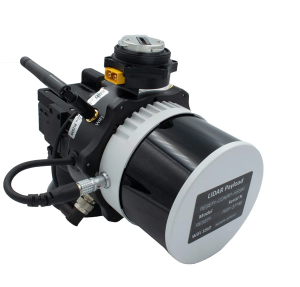
Inertial Labs has released a remote sensing payload instrument. The Resepi Hesai XT32 laser is designed for accurate remote-sensing applications. The Resepi laser can be used with commercially available lidar scanners, including Velodyne, Quanergy, Ouster, RIEGL, LIVOX and Hesai, as well as with UAVs.
Resepi is completely modular, so users have full control for customization. The remote sensing device uses a GPS-aided inertial navigation system with NovAtel RTK/PPK single- or dual-antenna GNSS receiver, integrated with a Linux-based processing platform. It also comes with a 2 TB USB memory drive and has an embedded Wi-Fi cellular modem.
Resepi has 3-5 cm point-cloud accuracy and can reach heights of more than 200 m above ground level. It is compatible with most UAV models; however, it is typically used with DJI M300, DJI M210 or DJI M600 models.
The device is suitable for scanning and mapping, precision agriculture with lidar, simultaneous localization and mapping (SLAM) algorithm development, utility inspection and construction site monitoring. Resepi-supported software includes Hexagon NovAtel, PCPainter and PCMaster.
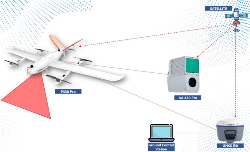
CHC Navigation’s mobile mapping solutions, the P330 Pro vertical take-off and landing unmanned autonomous vehicle (VTOL UAV) and the AlphaAir 450 lidar, are being used for mining exploration in Indonesia. The solutions help with effective data collection to measure the volume of an open-pit mine.
The P330 Pro UAV and the AlphaAir 450 provide an effective surveying solution, which is critical to the life cycle of mining projects. During this operation, the solutions covered more than 5 km² per mission, with an error of less than 5 cm. Accurate lidar in vegetated areas enabled surveying of the ground surface, including structures missed by other surveys due to dense vegetation.
A CHC Navigation i50 GNSS receiver and processing software provided with the AlphaAir 450 were deployed during the operation.
The P330 Pro UAV enables small- and large-scale aerial surveying. It comes with a portable ground control station for remote control and communication between the UAV and its operator. The UAV is designed for vertical takeoff and landing, making it convenient to operate and transport.
The AlphaAir 450 is a lightweight and rugged system, which integrates lidar with an industrial-grade professional 26 MP camera and an inertial navigation system for data collection.
My previous column provided an update on the current set of published orthometric heights in the southeast Texas region and rules by the National Geodetic Survey (NGS) for estimating and publishing GNSS-derived orthometric heights using OPUS Projects. It also highlighted my personal crusade, that is the United States geodesy crisis. The Geodesy Crisis white paper can be downloaded from the American Association for Geodetic Surveyingwebsite.
This column focuses on potential errors in orthometric heights using a digital barcode leveling system with multi-piece leveling rods. Every business makes decisions based on expenses and ultimately on the profit margin. That said, making a business decision that results in a bad technical outcome may lead to issues that cost the company more than expected.
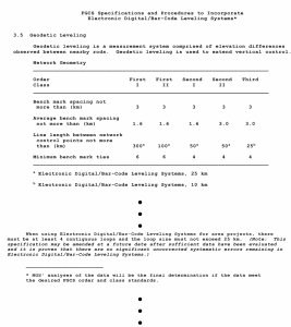
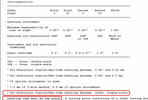
I have been involved with establishing orthometric heights, both leveling-derived heights and GNSS-derived heights, for most of my career. On a personal note, the digital bar code leveling system is important to me because I was the lead author of the document by the Federal Geodetic Control Subcommittee (FGCS) to incorporate the digital barcode leveling systems “Specifications and Procedures to Incorporate Electronic/Digital Barcode Leveling Systems (2004).” Recently, a colleague brought to my attention that many surveyors are using the digital barcode leveling system (which wasn’t a surprise to me), but they are not using the one-piece, single-scale, invar rod. They are using the multi-piece rods, either fiberglass or wooden. Surveyors can use any type of instrument to perform their project, but it will not meet the Federal Geodetic Control Subcommittee specification and procedures for leveling unless they use a one-piece leveling staff. This not a new requirement; it has been a requirement since the first publication of the FGCS specifications and procedures. Surveyors have always requested to use multi-piece rods but the potential errors associated with them were considered too large to be incorporated into the specifications and procedures to meet first-, second-, or third-order U.S. federal accuracy standards.
Excerpt from FGCS Specifications and Procedures (Image:FGDC)Excerpt from FGCS Specifications and Procedures (Image:FGDC)
In 2018, NGS documented a study to evaluate the use of multi-piece rods using the digital barcode leveling system. I first saw a draft of this report in 2011 and forgot that it existed. A colleague of mine recently provided me with the 2018 report. In my opinion, anyone who uses the digital barcode system and multi-piece rods should read this report and, of course, the rest of this column.
NOAA Technical Memorandum NOS NGS 75. (Image: NGS)
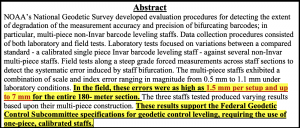
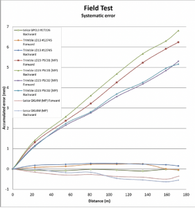
The image below provides the important summaries of the tests. I highlighted the statement “In the field, these errors were as high as 1.5 mm per setup and up to 7 mm for the entire 180-meter section.” In my opinion, an error of 7 mm in a 180-meter section is too large for any order and class of leveling. Also, the results of the study support the current FGCS specifications and procedures requirement of the use of one-piece, calibrated rods.
Image: NGS
The 2018 report states that multi-piece level staffs are popular among the surveying community because of their ability to break down into an easily transportable unit and they are relatively inexpensive and readily available. They may also be extended to reduce the number of leveling setups required over sloping terrain. This makes good business sense but surveyors should not make technical decisions based solely on business costs. That said, the FGCS “Specifications and Procedures to Incorporate Electronic/Digital Barcode Leveling Systems (2004)” prohibit the use of multi-piece rods for any order/class of leveling based on technical decisions, not on business expenses. To evaluate the multi-piece barcode rods, NGS developed and implemented laboratory and field tests designed to detect and quantify possible loss of precision in multi-piece leveling staffs. All their tests were conducted at the NGS Testing & Training Center located in Woodford, Virginia, in December 2011. The report was published in 2018.
The report did note that only a small sampling of instrumentation, three multi-piece leveling staffs comprising two separate models from two separate manufacturers, were included in the NGS study. Therefore, the results found within the report evaluate the accuracy and precision of the specific staffs tested. As the report states: “The tests are qualitative in nature with respect to bifurcation and non-Invar construction. Similar results are expected for similarly designed level staffs; nevertheless, the results should not be considered precisely valid for all types or models of multi-piece leveling staffs.”
Users should download the document and read it but I’ll highlight a few results. First, the report made the following statements about the plumbing of the rods:
“With the Leica GKNL4M level staff carefully plumbed, the section directly above the bottom section housing the level vial was visually slightly out of plumb. No correction was made for this effect in the lab or field tests. No measurements were made to the top third section of this level staff during this evaluation.”
“With the Trimble LD23 level staff carefully plumbed, the sections directly above and below the middle section housing the level vial was visually bowed and slightly out of plumb. No correction was made for this effect in the lab or field tests.”
Obviously, having a correctly plumbed rod is extremely important.
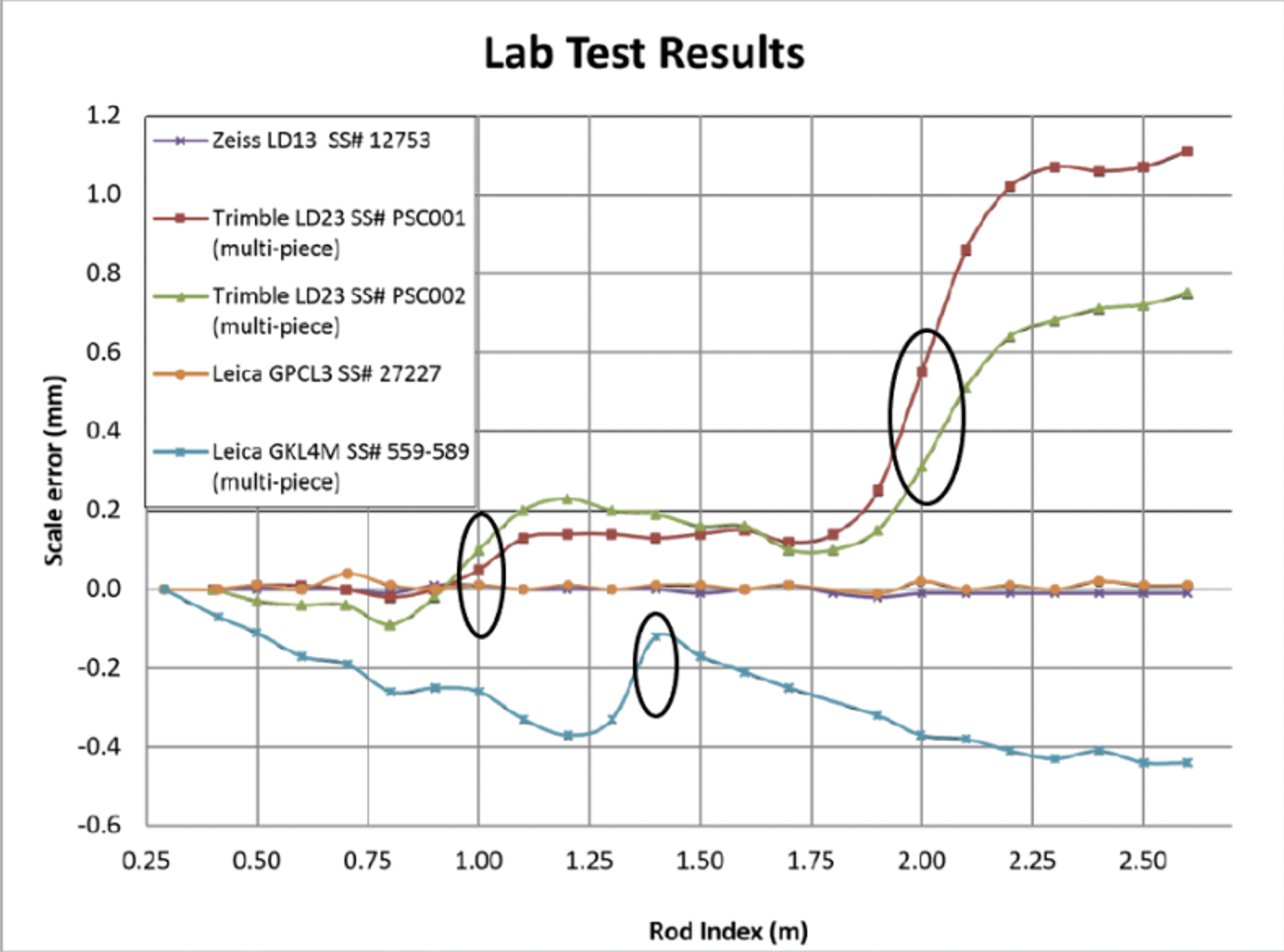
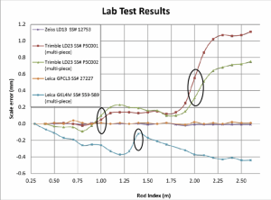
To estimate the potential scale error in a controlled environment, NGS performed a special test where they set up the level instrument 5 m from the leveling rods inside their building and made a measurement every decimeter on each rod. To perform this, the level instrument was moved upward one-decimeter after each measurement and the measurement was repeated. Figure 9 from the 2018 report depicts the results of the process. The first thing to notice is that the two calibrated, invar rods indicate very small errors. The other thing to notice is that there is a change in scale error at the section breaks of the multi-piece staffs. I highlighted the section breaks in the image below. The plots in Figure 9 indicate that the upper section of the rod is different from the lower section. This may result in a large error when going up (or down) an incline; that is, when leveling up an incline the upper section of a rod would be read in the back-sight reading and the lower section of a rod would be read in the foresight reading. The opposite would occur going down the incline.
Figure 9 from NGS 2018 report. (Image:NGS)
NGS also performed a small field test. The height difference was only 10 m over about 180 m distance. Figure 15 from the report provides the results of their field test. Some of the rods showed an error of almost 7 mm in the 180-meter section. Obviously, this is a significant error over such a short leveling distance, especially since it appears to be systematic. The report made a note about the systematic error; it noted that the height differences between the forward and backward runs were similar, but they were different from the standard. In other words, the forward and backward runs may meet a FGCS section misclosure but the mean difference would still have the accumulated systematic error. This means that following double-run procedures will not account for the systematic error. As a side note, according to FGCS specifications and guidelines, for establishing a height of a new bench mark, double-run procedures must be used. Single-run methods can be used to re-level existing work provided the new work meets the allowable section misclosure.
Figure 15 from NGS 2018 Report. (Image:NGS)
As stated in the 2018 report, errors as large as 6.8 mm over a 180-meter sloping section were due to using the multi-piece leveling rods. This is unacceptable for meeting FGDC specifications and procedures for leveling surveys.
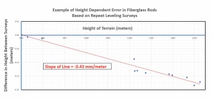
The NGS report was based on a small sample and over a very small project area. It provides a compelling argument for requiring one-piece leveling rods. Now, for a real-world example that supports the results of NGS’s study. I received a report where the results of repeat leveling surveys using the multi-piece fiberglass rods over the same basic route indicated a large systematic height error. The figure below provides the difference in heights between the two surveys. As indicated in the figure, the data indicates a height dependent error of -0.43 mm/meter between the two surveys. In this example, the difference approaches 200 mm. Clearly this type of systematic error needs to be accounted for when multi-piece barcode rods are used in a survey.
Example of Height Dependent Error in Fiberglass Rods. (Image: Dave Zilkowski)
As previously stated in the conclusion of NGS’s 2018 report, “Calibration of these type survey instruments provides a means of quantifying these type error sources, thus providing a mechanism for ‘correcting’ for them during post processing of data sets.” If a company or agency created a calibration process similar to NGS’s test site, then surveyors could use the site to evaluate their multi-piece barcode rods. In my opinion, until users account for the index and scale error in multi-piece barcode leveling rods, they should not be used to perform leveling surveys to compute orthometric heights with any expected accuracy value.
Clearly, it is more cost effective to use multi-piece rods instead of single-piece invar rods because of the increase in expenses for the single-piece invar rods. However, making a business decision that results in a bad technical outcome could lead to lawsuits, professional liability issues, and/or additional expenses for having to resurvey projects. Enough said.
The Open Geospatial Consortium (OGC) is calling for participants in Disaster Pilot 2023, which aims to reduce disaster preparation time and accelerate transforming data into decisions. All responses are due by Feb. 17.
Disaster Pilot 2023 aims to enable key decision makers and responders to discover, manage, access, share and exploit location-based information to support disaster preparedness and response. The focus of this year’s pilot is to update the OCG Disaster Readiness Guides on flooding and landslides to include information on wildfires and droughts.
The pilot provides the opportunity for participants to collaborate with a range of disaster stakeholders, including Earth observation data providers, relief organizations and field responders. The goal of the pilot is to help shape the future of disaster management systems through user-centric interoperability arrangements, identification of critical data sharing challenges, and the delivery of cloud computing scale and agility to field personnel and relief organizations.
The Disaster Pilot 2023 is being conducted under OGC’s Collaborative Solutions and Innovation Program.
A Q&A session is available on Feb. 1 for interested participants. For more information, visit the Disaster Pilot 2023 page.
Paris Austin, head of product – New Technology for OxTS, tries out the new backpack at historic Minster Lovell Hall. (Image: OxTS)
More than 400,000 sites in the United Kingdom are on its historical registries. English Heritage site Minster Lovell Hall is located in Oxfordshire, also the home county of inertial navigation company OxTS. The picturesque ruins of Minster Lovell Hall, a 15th-century manor house, include the hall, a tower and a nearby dovecote.
The hall was built in the 1430s by William, Baron of Lovell and Holand — one of the richest men in England. It was later home to Francis, Viscount Lovell, a close ally of Richard III. After changing hands several times, the hall was abandoned and eventually demolished in the 18th century, leaving the extensive remains that stand today.
(Image: OxTS)
The buildings are grouped around a central courtyard in a plan characteristic of a late medieval manor house. For OxTS, the site proved suitable for testing its prototype backpack. The site features dense tree canopies on one side, tight doorways, narrow views of the sky, and plenty of height to test the angled mounting of the survey-focused lidar for when GNSS is denied. Open-sky areas allowed the OxTS team to return to real-time kinematic (RTK) surveying before moving on to another section of the site.
Reconstruction drawing of Minster Lovell Hall as it might have appeared in the 15th century, by artist Alan Sorrell. (Image: English Heritage)
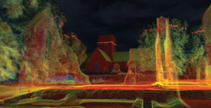
The prototype backpack is based on the OxTS setup for vehicles but was created to enable quick data collection without a car. It is equipped with two Hesai lidar sensors, a new OxTS prototype inertial navigation system and an antenna. The team can connect it to a laptop for configuration and to optimize lever arms and the boresight. Once post-processed with OxTS Georeferencer software, the point cloud below was produced.
OxTS designed the backpack to meet a growing need for localization and georeferencing in both GNSS-denied areas and those that cannot be reached by car, including the construction, environmental, conservation and heritage industries.
Movella, a leading provider of sensors and software, has launched a partnership with Fixposition, a manufacturer of precise positioning sensors. The partnership aims to develop and commercialize GNSS inertial navigation sensors and implement visual inertial odometry through new products.
In December 2022, Movella and Fixposition launched the first product from the partnership, the Xsens Vision Navigator. This product integrates position inputs from three high-accuracy sources including dual-antenna RTK GNSS receivers, an IMU incorporating a three-axis accelerometer, gyroscope and magnetometer and a visual inertial odometry system.
The Xsens Vision Navigator can optionally accept inputs from an external wheel speed sensor. The positioning sensor achieves centimeter-level accuracy when operating in GNSS mode with an RTK fix. When GNSS signals are not available, the product alone achieves an accuracy of 2% of travel distance, or 0.75% when supplemented by wheel speed.
Xsens Vision Navigator is suitable for outdoor positioning applications such as material handling equipment, commercial and specialist vehicles, last-mile delivery, inspection equipment and UAVs, agricultural equipment, mining equipment and utility robots.
Xsens Vision Navigator is available now from Movella or authorized distributors of Xsens products.
MGISS, a United Kingdom-based geospatial technology company, has launched the Interruption Prevention Alert Service (IPAS) project to help minimize disruptions to gas and water supplies in the UK. The European Space Agency (ESA) has partly funded this project, which will run for two years to test its technical and commercial viability and to develop a go-to-market plan.
As gas and water outages caused by construction are a growing problem in the UK, IPAS will offer a preventative solution. By leveraging satellite data and services, IPAS will automatically detect changes to the built environment and alert utility providers. The IPAS is expected to be a cost-effective solution and help utility providers reduce carbon emissions.
MGISS is collaborating on this project with Geospatial Insight, its data partner, Northumbrian Water Group (NWG) and Northern Gas Networks (NGN), its client partners, and funding partners including the ESA and the UK Space Agency (UKSA).
The launch of the pilot project is the result of a joint workshop with ESA and NWG’s 2020 Innovation Festival, and two years of ongoing collaboration with NWG and NGN.
Image: Vincent Ryan/iStock/Getty Images Plus/Getty Images
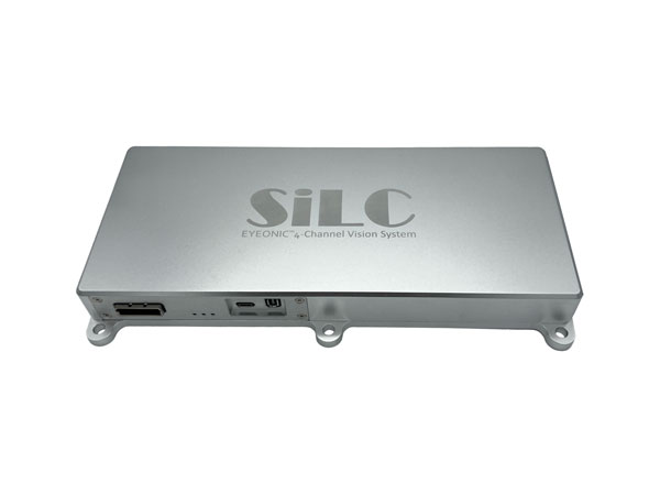
SiLC Technologies has launched the Eyeonic Vision System. This system is a frequency-modulated continuous wave lidar solution, which delivers high levels of vision perception to identify and avoid objects with low latency.
At the core of the Eyeonic Vision System is SiLC’s fully integrated silicon photonics chip. It provides more definition and precision than legacy lidar solutions, with roughly 10 milli-degree of angular resolution coupled with millimeter-level precision. These features enable this solution to measure the shape and distance of objects with high-precision and at a large distance.
The system combines the Eyeonic Vision Sensor and a digital processing solution based on a powerful field-programmable gate array. The flexible architecture enables synchronization of multiple vision sensors for unlimited points per second.
SiLC demonstrated the Eyeonic Vision System at CES 2023. It was named by the CES award committee as an honoree for the CES Innovation Award.
The compact, powerful, vision solution is suitable for autonomous vehicles, smart cameras, robotics and other advanced products. It is available now. Pricing varies depending on configuration.
Ness Czech will supply the Czech Railway Administration with a Digital Technical Railway Map (DTRM) with help from Hexagon’s Safety, Infrastructure and Geospatial division. The DTRM project has been underway since September 2022 and will be implemented by 2025.
DTRM is a railway-specific geographic information system (GIS), that provides access to transport and technical infrastructure information to better prepare investments and repair work. The basis of the DTRM project is the Technical Map Information System (ISTEM) developed by Ness and Hexagon.
The project includes digitization and consolidation of all available Czech Railway Administration data, covering more than 9,200 km of tracks, 27,000 km of technical infrastructure and an area of 21,000 ha. The delivery also includes three data centers.
The project is a legislative obligation of the Czech Railway Administration as the state is developing a national map, which will be fully operational by 2024. The Digital Technical Map of the Czech Republic is being built across the country by connecting regional digital maps, maps from the Railway Administration and maps provided by the Directorate of Roads and Highways. The connection is provided by the Czech Land Surveying and Cadastral Office.
On Jan. 6, ROCK Robotic, a geospatial company specializing in lidar-based data processing and high-definition mapping, announced the availability of ROCK Base, a triple frequency RTK base station. Additionally, ROCK Robotic has partnered with the Web3 GEODNET initiative to support critical applications in civil surveying, high-definition mapping, digital twin creation and more.
ROCK Base is a resilient, secure, full-constellation GNSS receiver, capable of tracking signals transmitted from GPS, GLONASS, Galileo, BeiDou, QZSS, and the IRNSS navigation satellite constellations. It includes 1,400 channels, survey-grade antennae, cables and antennae-mounting equipment required to set up a permanent continuously operating reference station location.
To make high-definition mapping more accessible and affordable, ROCK Robotic joined the Web3 GEODNET initiative, the largest decentralized GNSS reference network globally. Under the new partnership, ROCK Robotic customers will have access to the GEODNET base-station network to geo-reference ROCK Robotic’s 3D data products to millimeter-level absolute position accuracy, without setting up ground control points. Additionally, ROCK Base is pre-certified on the GEODNET network.
Tactical-grade IMUs enable UAVs to achieve the same locational accuracy as ground-based systems. (Photo: CHC Navigation)
We often hear the anecdote about an early lidar scanner that could take a shot every few seconds, yet it held a value proposition for certain applications. As the capabilities of successive mapping and surveying systems change rapidly, so does the conventional wisdom about which are best for various applications. Transportation corridor mapping — be it for improvements design, as-built surveys, asset management or digital twinning — has always been a balancing act between precision and efficient large-scale data capture.
“I remember 15 years ago, during my university time, the scanner was the size of a dining table,” said Andrei Gorb, segment manager for mobile mapping and unmanned aerial vehicle (UAV) systems, CHCNAV. At the top end of the mapping food chain were terrestrial scanners, targets, bore sighting, and registering point clouds mostly manually. As cumbersome and time-consuming as the legacy tools and methods were, these options still offered efficiency gains compared to conventional surveying with total stations. Then a decade ago, mobile-mapping systems began to change that paradigm. Departments of transportation found that mobile-mapping systems could meet their requirements for many design projects, and certainly for asset inventory and management. Unmanned aircraft systems (UAS) were not quite there yet.
The tech used depended on the application. “First, there was road maintenance, to understand the road condition,” Gorb said. “Previously, UAS did not meet the high requirements: centimeter in absolute and millimeter in relative. We now have mobile-mapping solutions, from us and other suppliers, that can be in the 8-9 mm absolute accuracy range on short road surfaces.” Yet for many transportation applications, the absolute accuracy may not be as important as the relative precision. This is where years of development in UAS has made the difference.
CHCNAV was not alone in recognizing that the gap was closing, and the company planned ahead. “Previously, UAS would fly for under an hour, and were mostly carrying cameras or early lidar, which was not suitable for highways,” Gorb said. “A few years of development, and we see it is practical to meet requirements with UAS flying between 50 and 100 meters — in Europe, many local regulations forbid flying above 120 meters anyhow.” Gorb attributes the advances to lidar sensors that UAS can carry. These sensors have become much better and less expensive. Plus, platforms like vertical-take-off-and-landing (VTOL) systems can stay in the air much longer.
The UAS boom of the past 10 years saw the dominance of consumer-prosumer market UAV platforms becoming quite commoditized, with certain vendors gaining majority market share. CHCNAV, instead, sought to develop enterprise solutions, for both mobile and UAS systems — large-platform rotor, fixed-wing and VTOL platforms. The company offers an amalgam of hardware and software, from Riegl scanner heads on some of their mobile-mapping systems to Honeywell inertial navigation systems (INS) for some of their UAS solutions.
Gorb echoes what we hear from many mapping practitioners, saying ground-control points are not as necessary in the densities required for legacy mobile and UAS mapping. He explained that everything from strip adjustments to processing of GNNS/IMU data has tightened both precision and accuracy. “We have a tactical-grade IMU in both our mobile mapping and UAS solutions, for a high-end trajectory,” Gorb said. “So, it means that we can get the same high-accuracy point cloud for highways from the ground and the air perspectives.”
Trimble Maps enables a shipping company to offer one-hour delivery windows. (Photo: Trimble)
To reduce its emissions, DPD Deutschland — a franchise of DPDgroup, one of the largest international parcel carriers in Europe — has asked Trimble Maps to help optimize its operations. DPD Deutschland’s parcel supply chain covers 80 franchise depots, 9,500 employees and more than 13,000 drivers, delivering about 2 million packages to businesses and consumers per day via a mixed fleet of vehicles, including electric ones.
DPDgroup has a vision to become the international standard in sustainable delivery by 2030. Per parcel, it has reduced its CO2 emissions by 18.8% since 2013 and is on track to reach a 30% reduction by 2030, according to Trimble.
One of DPD’s most popular service offerings, called Predict, allows parcel recipients to track the progress of their deliveries in real time, with an estimated one-hour delivery window and updated notifications along the way. Since 2014, Trimble Maps’ portfolio has helped calculate this one-hour delivery window and provided turn-by-turn navigation to DPD drivers, resulting in less overall travel time, more successful first-time deliveries and reduced emissions.
DPD was the first, and still is the only, parcel carrier in Germany that provides recipients with an estimated one-hour delivery window, the company says, calculating it for every parcel. The service is made possible in part by the integration of Trimble Maps’ route optimization and mapping web services platform, known internally as DPD Maps. Recipients can reschedule deliveries as needed for future days and times, or perhaps to a convenient drop-off location. This reduces emissions created by multiple return trips.
DPD Maps calculates an optimized route for drivers, who are then able to manually sort the stops and change the route to best fit their preferences. Once routes are locked in, Trimble’s commercial navigation application, CoPilot, provides drivers with real-time directions. Once a driver’s route is complete for the day, DPD can compare the actual route taken with the optimized route DPD Maps calculated in an easy-to-understand view that can be analyzed by the driver and the depot.
DPD Maps allows the company to visualize, share and discuss results with different stakeholders within the organization. The solution also allows drivers to plan out their day as they see fit, while giving the back office access.