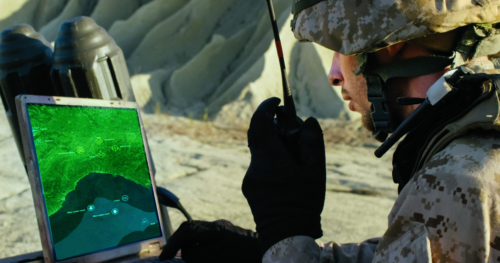
uAvionix has introduced truSky ADS-B spoofing detection for its SkyLine uncrewed aircraft system (UAS) beyond visual line of sight (BVLOS) services.
The uAvionix truSky validation process uses a network of low-profile deployed dual-frequency ADS-B ground receivers to evaluate each signal transmitted from the aircraft. The system then compares the received signals to confirm that the signal originated from the aircraft’s position.
When used within the uAvionix SkyLine platform, each aircraft track point is color-coded based on its confidence score. The validation score is then transmitted along with the position updates of the aircraft using SkyLine API.
TruSky is being piloted in numerous locations in the United States and is available as a component of uAvionix’s SkyLine UAS BVLOS service or as an API for integration into uas GCS, UTM, or ATM platforms.
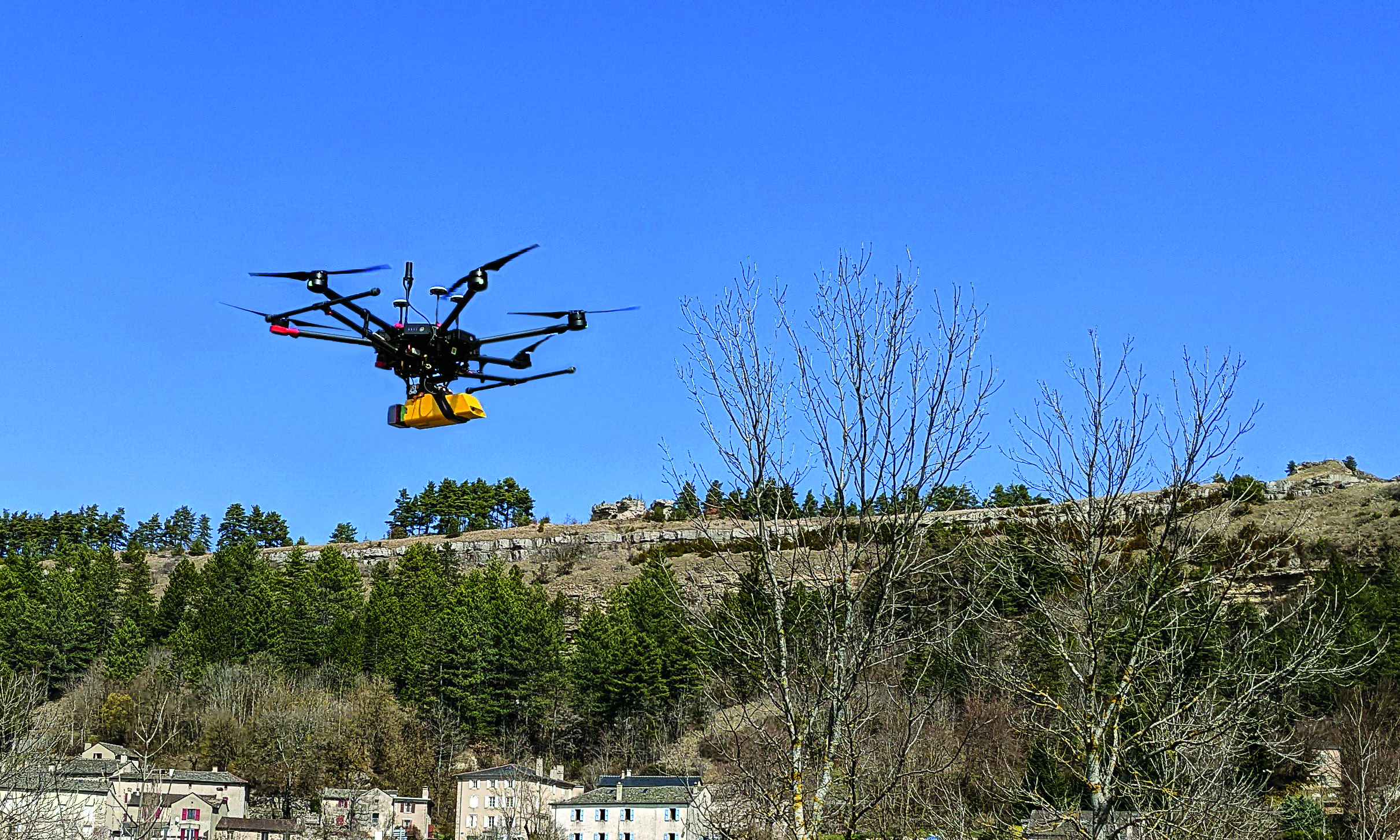
L’avion jaune, a French UAV and aerial photogrammetry company, uses the Trimble Applanix APX-20 UAV GNSS-inertial OEM solution and a YellowScan VX-20 lidar on its M600 multirotor UAV. (Image: L’Avion Jaune)
The breakdown of limestone cliffs generates landslides and loose debris that threatens the environment, people and wildlife below. These conditions make it impossible to safely operate traditional survey equipment from the ground for landslide detection. Using UAVs for direct georeferencing is an efficient way to take traditional survey efforts to the sky and enables users to accurately assess land formations while mitigating risk.
One way to implement direct georeferencing on UAV platforms is with the Trimble APX-20 UAV, which is a GNSS-inertial OEM solution that increases the mapping efficiency of small UAVs. It consists of small, low power, precision GNSS and inertial hardware components and POSPac UAV post-mission differential GNSS-inertial office software. The APX-20 UAV eliminates the need for ground control points and reduces the sidelap required to be flown per flight.
The APX-20 UAV contains a precision, survey-grade GNSS receiver and dual inertial measurement units (IMU), so it automatically supports integration on gimballed platforms without requiring an external interface to an autopilot or on a mount. It computes at 100 hz using the embedded IMU while simultaneously logging the raw IMU data from both the internal and external IMU at 200 hz for post-processing in POSPac UAV. The postprocessed position and orientation solutions are suitable for direct georeferencing of cameras, lidars and other sensors.
Trimble Applanix UAV Put to the Test
For fast and safe landslide detection, the Trimble Applanix APX-20 UAV for direct georeferencing was put to the test using a Multirotor M600 manufactured by French company L’Avion Jaune equipped with a VX-20 lidar sensor made by YellowScan, also a French company. This combination produces cost-effective and reliable high-resolution UAV lidar-derived DTMs and 3D models for hazard mitigation and planning.
L’Avion Jaune has performed more than 600 successful mapping missions globally. After pursuing mapping activities with mainly crewed aircraft, it began developing UAVs for long-distance applications for marine, tropical forest and polar regions such as the Multirotor M600/YellowScan VX-20, which offers high-precision, cost-effective and efficient aerial mapping.
The APX-20 UAV and the M600/YellowScan VX-20 were combined and deployed to evaluate landslide activities in France. The mission parameters for this configuration included: high point density; x, y, z precision of 5 cm; access to dangerous zones; map generation under dense vegetation area, and fast deployment. The goal of this project was to enable the implementation of safety and prevention plans for the protection of pedestrians, infrastructure, wildlife and more.
During the six-hour duration of the project, the APX-20 UAV and M600/YellowScan VX-20 configuration was flown four times for 15 minutes each during sunrise. It flew more than 75 ha in surface area with a flight speed of 5 m/s at 60 m in the air, following the topography. Checkpoints were surveyed with differential GPS following the conclusion of the flights. Data processing included computation of the georeferenced trajectory, matching flight lines and point cloud classification, which took two days.
The Results
The flexible UAV deployment of resources enabled the acquisition of dense point clouds and the generation of DTM in less than three days. During this project L’Avion Jaune was able to optimize the choice of material and discover the best practices to collect and process lidar data for mapping in dense vegetation.
Bluesky International and SkyFi have collaborated to provide access to Earth observation assets and multi-perspective imagery to users globally. Bluesky is providing its high-resolution aerial imagery, taken by aircraft-mounted cameras, to SkyFi to make available for businesses, forestry, water and land managers across the United Kingdom.
SkyFi aims to make Earth observation data more accessible to users through its growing network of satellites and aerial platforms. The company has created a data marketplace where users can purchase existing images or task a satellite to purchase a new image.
Bluesky provides a wide range of geospatial data products and services to users across the United Kingdom. GIS and CAD-ready imagery from Bluesky captures ground terrain, cityscape rooftops, fauna and more. The company’s catalogue of aerial imagery is available in England, Scotland, Wales and the Republic of Ireland.
NV5 Geospatial has mapped more than 26 million acres of North America’s shoreline and riverine environments across more than 200 projects.
The projects have spanned from the Nuyakuk River in Alaska, Lake Tahoe in California, the Rio Grande in Texas, the entire coasts of South and North Carolina, the Achigan River in Quebec, Chesapeake Bay in Maryland and the Florida Keys.
In 2022, the company mapped and acquired topobathymetric lidar data for 14 projects including the Yellowstone River, Wyoming; Hells Canyon, Indiana; Revillagigedo Island, Alaska and Iles de la Madeleine in Quebec.
NV5 Geospatial first mapped these environments in 2012 using high-resolution bathymetric lidar and natural color imagery. The company mapped 34,051 acres of shoreline along the Sandy River, located in northwestern Oregon, to study the ever-changing basin geomorphology.
NV5 has also signed a two-year contract with the National Geodetic Survey of the National Oceanic and Atmospheric Administration to provide topobathymetric lidar, 4-band imagery and mapping of 3,115 sq miles of the Maine shoreline.
“For a decade we have been helping local, state, and federal government agencies as well as commercial and private entities gain the insights they need to solve some of their most challenging nearshore and riverine projects through our mapping technologies including topobathymetric lidar,” Kurt Allen, vice president of NV5 Geospatial, said. “Whether it be mapping the shoreline after a hurricane, updating the national shoreline, assisting water boards with flood planning, or hundreds of other possible use cases, we are constantly improving our technology and scalability to always be at the ready for our customers.”
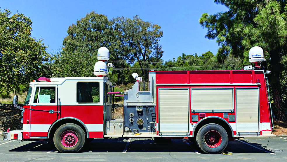
NASA-JPL prototype of POINTER base units on a first responder vehicle. The magneto-quasistatic fields they generate can be detected through walls, where legacy indoor positioning technologies fail. (Image: Jet Propulsion Laboratory)
A tragedy in 1999 spurred development of an entirely new type of positioning and location technology. “This project started with the Worchester, Massachusetts, warehouse fire,” said William Stout, program manager for the Department of Homeland Security (DHS) Science and Technology Directorate (S&T). “Six firefighters went in to clear an abandoned warehouse that was on fire to make sure there wasn’t anybody in there, and they got trapped. The team couldn’t find them because they had no idea where they were, and they ended up perishing.
That is what got DHS started with developing a first responder location tracking technology, Stout said.
“Over the years from that point on, we investigated many different technologies. My predecessor referred to most of these as ‘cocktail solutions’ because they would try to merge different types of technologies — for example, GPS and inertial — but none of these panned out.”
Enter Magnetoquasistatics Research
This lack of progress changed in 2012 when they connected with Darmindra Arumugam, group supervisor, senior research technologist and program manager at NASA’s Jet Propulsion Laboratory (JPL). Caltech manages JPL for NASA. In a complete departure from traditional radio signal-based positioning technologies, Arumugam and his team had been researching magnetoquasistatics (M/QS). This is the foundation for the POINTER System.
The system consists of fixed or portable transmitters, for instance, a base unit and controller that can be mounted on a first responder vehicle outside of a building. The first responders carry a small receiver that the base can locate with two characteristics: the field’s strength (for ranging) and its unique pattern (for lack of a better term) for direction (receivers send position info back to the controller via ISM band LoRa). The controller registers and displays the position of each receiver.
Why Magnetic Fields?
Ranging can be done in many modes, Arumugam said, and not all are based on just the amplitude of the propagating wave. With traditional radio signal ranging, to compute a precise position, techniques mostly use multiple sources of signals, for trilateration or multilateration, as GNSS does. However, signals can be perturbed by objects in their path, or experience multipath (signals bouncing off objects), which is a pronounced challenge for indoor environments.
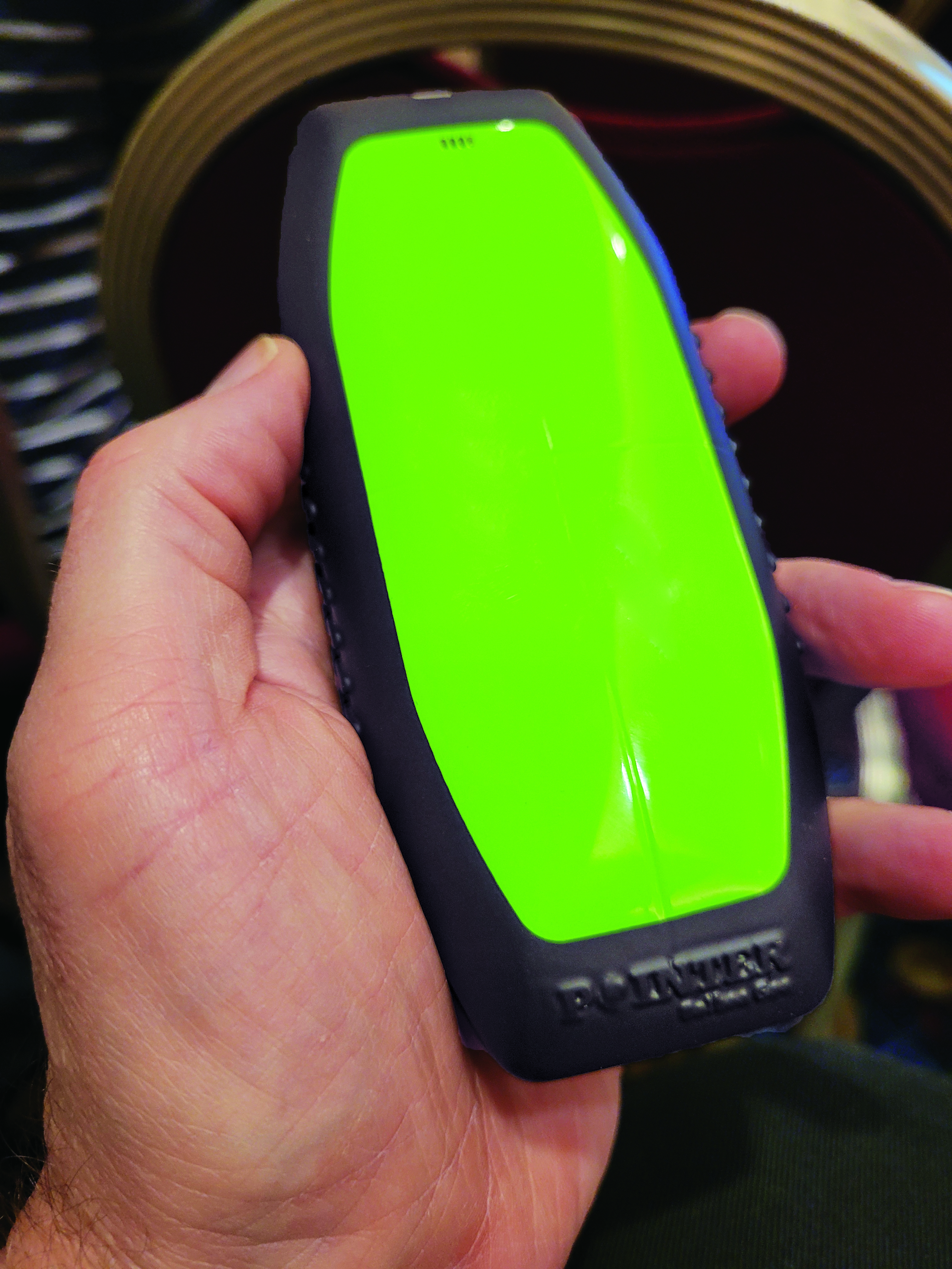
The portable POINTER receivers can be clipped by first responders to their belt, harness, or personal protective equipment, reporting their position in a building, and viewable by an incident commander on a laptop. (Image: Gavin Schrock)
POINTER does not employ radio signals in the fashion of traditional ranging solutions such as GNSS, ultra-wide band (UWB), and various beacon systems for indoor positioning. However, Arumugam said POINTER does generate a radio signal.
“The key difference is that we are detecting the field in a regime where there is no radio propagation mode. Therefore, it is more accurate to refer to this as a quasi-static field, as opposed to a radio propagating wave,” Arumugam said.
Arumugam said Earth’s magnetic field is a good example of this. “It penetrates structures very well, we can measure it 100 kilometers beneath the surface, far above the surface, inside buildings, underwater and so on,” he said. “POINTER uses the kind of the features that you see in Earth’s magnetic field — we are generating quasi-static magnetic fields.
“The term quasi-static highlights the fact that we are trying to keep the physics of the field stationary for all purposes but apply some slow time variation so that it’s really quasi-static to optimize the benefits from both,” Arumugam said. “We get the best of the behaviors of static fields in terms of penetration and non-line-of-sight capability, but also optimize for signal-to-noise by making this a quasi-static signal as opposed to a perfectly static one.”
JPL developed for DHS S&T prototypes that the two organizations tested jointly. Both transmitters and receivers employ an array of three coils, oriented at right angles for x, y and z. The resultant transmitted field carries distinct patterns from these three axes. Distance is detected from field strength, and direction is determined by detecting the pattern of the field relative to the three axes. A key strength of POINTER is that it can achieve ranging and direction from a single base station.
However, Arumugam noted that multiple bases could be beneficial for certain situations.
“The technique as originally developed requires only one transmitter. However, we find that there’s only so much you can get out of a magnetic field, and certain types of structures and materials will perturb that field, causing error.” The second transmitter is not only a backup, but it also helps reduce errors.
POINTER
Geolocation Inc. was spun out from Caltech to license and commercialize POINTER, said Joseph Boystack, executive chairman and co-founder. “We stepped in and executed an exclusive worldwide license for every field of use on this technology in late 2020 from JPL. They had established a proof of concept, and begun testing the technology in the field.”
For the initial commercial version, Balboa Geo made significant improvements over the JPL prototype system. It developed two transmitters that can be deployed on a fixed-mounted basis (buildings, vehicles, ships, etc.) or be portable housed inside a ruggedized, military specification (MIL-STD) case, with a built-in dual antenna GNSS receiver (to position and orient the transmitter).
“If you have an incident involving first responders, military or industrial applications, these remotely configured transmitters can be quickly and easily deployed,” Boystack said. “Also very important, because it only needs to depend on the field generated by the transmitter, we’re not dependent upon other large, fixed infrastructure such as satellites, towers or beacons, and can work in degraded environments where most other position, navigation and timing techniques fail.”
The self-contained receivers are only about the size of a smartphone. The orientation of the receiver is important to determine the “xyz” axis relative to the generated field, thus providing highly accurate three-dimensional position and navigation data. For instance, Balboa Geo’s receiver can be clipped to a first responder’s belt, harness, or personal protective equipment. Similarly, for fixed assets or moving assets such as warehouse systems or robotics, the orientation would be known.
The POINTER system will generate real-time data that can be easily visualized at the job site or event by the incident commander or manager on a laptop or a tablet. The data is interoperable and may be ingested in third-party software applications.
This version meets DHS STS’s original expectations, and subsequent versions will build on it. “S&T relies on experienced emergency response and preparedness professionals to guide our research and development. The First Responder Resource Group is made up of hundreds of state and local volunteers,” Stout said. “We initially looked at tracking firefighters in some of the most common scenarios: two-story house fires.”
While POINTER technology has the potential for much longer ranges and precisions, the current version, Arumugam said, certainly meets the specifications for this initial application. “The current systems can operate up to about 75 meters in range from the transmitter. So, if a transmitter is placed about 10 meters outside the building, say on the fire truck, you can penetrate up to about 65 meters inside the structure. That covers many one, two, maybe three-story structures. Position accuracies can be one meter or less. In principle, you could get to a centimeter, but that’s not required for this technology to be the lifesaver it presently needs to be.”
JPL continues research and development to extend range and increase precision to enable DHS S&T to deploy this technology to ever broader safety-of-life applications where legacy technologies fall short or are completely impractical. Balboa Geo is conducting field and lab tests for many more applications across multiple industries including energy, construction, maritime, mining, the internet of things and more.
Sharper Shape has used SimActive software’s distributed processing capabilities to complete utility corridor base maps in Montreal, Canada. In 2022, more than eight million images were collected in SimActive’s Correlator3D software to generate orthomosaics and colorized point clouds.
Correlator3D, hosted on an Amazon cloud environment, enabled quick processing of thousands of images per day over a network of virtual machines. The resulting map products covered more than 34,000 miles of utility corridor and were imported into Sharper Shape’s artificial intelligence (AI) tools to extract infrastructure information.
“The quantity of data that we capture to feed our AI tools for utility infrastructure deliverables is incredible and comes from various geographical locations at the same time,” said Petri Rauhakallio, vice president of business development at Sharper Shape. “Correlator3D allows our teams to easily import and process massive amounts of imagery for use in our digital twin production.”
On Feb. 6, a magnitude 7.8 earthquake struck Turkiye and northern Syria creating enormous damage throughout both countries. (Image: mustafaoncul/iStock /Getty Images Plus/Getty Images)
Geographical information of urban areas is critical because it forms the basis for planning, intelligent urban modeling and disaster mapping and management. For many decades, ground surveys and aerial photographs were used as the primary tools for collecting this data. Starting in the 1990s, these methods were replaced by such advanced remote-sensing technologies as synthetic aperture radar (SAR) and ground-based interferometric radar (GBIR).
This article explores the use of software-defined radio (SDR) platforms for acquiring high-resolution SAR/GBIR images, including:
How low-cost commercial-off-the-shelf SDR platforms can be used to realize complex systems for acquiring images and processing measurements.
How different specifications of SDRs make them suitable for use in SAR applications.
Hazard Monitoring in Urban Areas
Many urban areas and critical infrastructure are in regions highly prone to natural disasters such as volcano eruptions, earthquakes, avalanches and landslides, or near man-made systems such as dams and quarries. Monitoring of surface changes and structures is integral to the mitigation of risk and ensuring public safety. Modern remote-monitoring systems allow surface displacements to be monitored without the need to access a location. With these systems, several square kilometers of Earth’s surface can be monitored at once and with high accuracy. The sub-millimeter accuracy of modern remote-monitoring technologies enables accurate measurements to be collected with impressive precision, including in rainy and foggy conditions.
Remote-monitoring systems are autonomous and can operate for a long time without human intervention. Their real-time feedback makes them suitable for use as early-warning systems. In addition, these monitoring systems can be integrated into a wide range of sub-systems, such as decision support systems that assist decision makers in assessing emergency plans and selecting the best options.
Using Radar to Measure
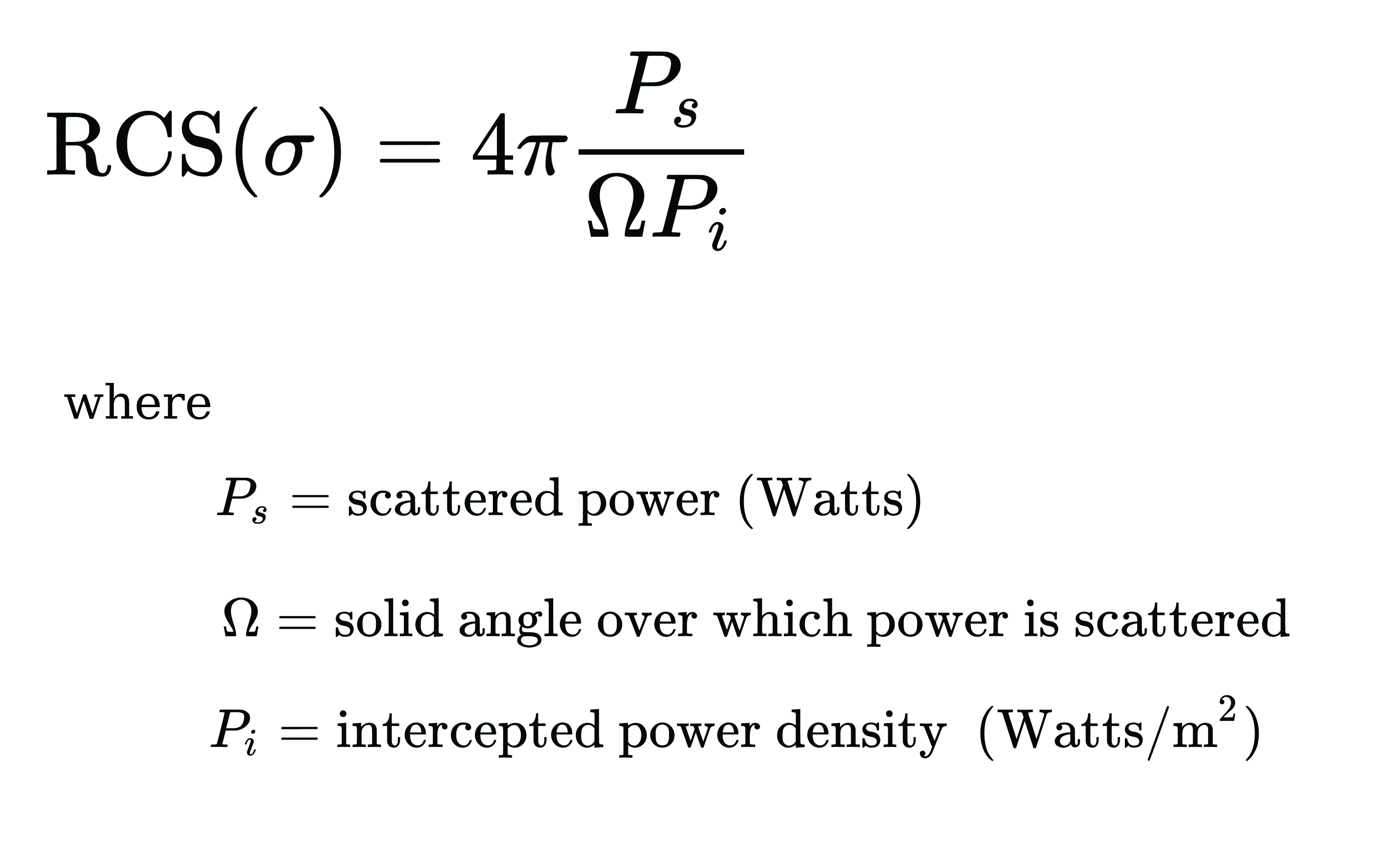
Details of the surface observed by a SAR satellite are encoded in the amplitude and phase of a SAR image. The amplitude component contains information about the surface roughness and terrain slope of the target area, while the phase component contains information about the elevation of the satellite.
A typical SAR satellite transmits microwave signals toward a target area at an oblique angle and measures the backscattered signal. The intensity of the reflected signal is mainly determined by the roughness and the structure of the target, and the distance between the satellite and the target. This measurement is usually described in terms of the radar cross-section (RCS) parameter, which is obtained by calculating the ratio of the scattered to the intercepted signals as shown in this equation:
The RCS parameter is mainly dependent on the surface roughness and the dielectric properties of the target object.
The interferometric SAR (InSAR) technique allows surface movements to be identified. These observations also can be used to measure and monitor changes associated with volcanic eruptions, tectonic activity and other geophysical processes. To identify crustal changes using this geodetic technique, at least two SAR images are required.
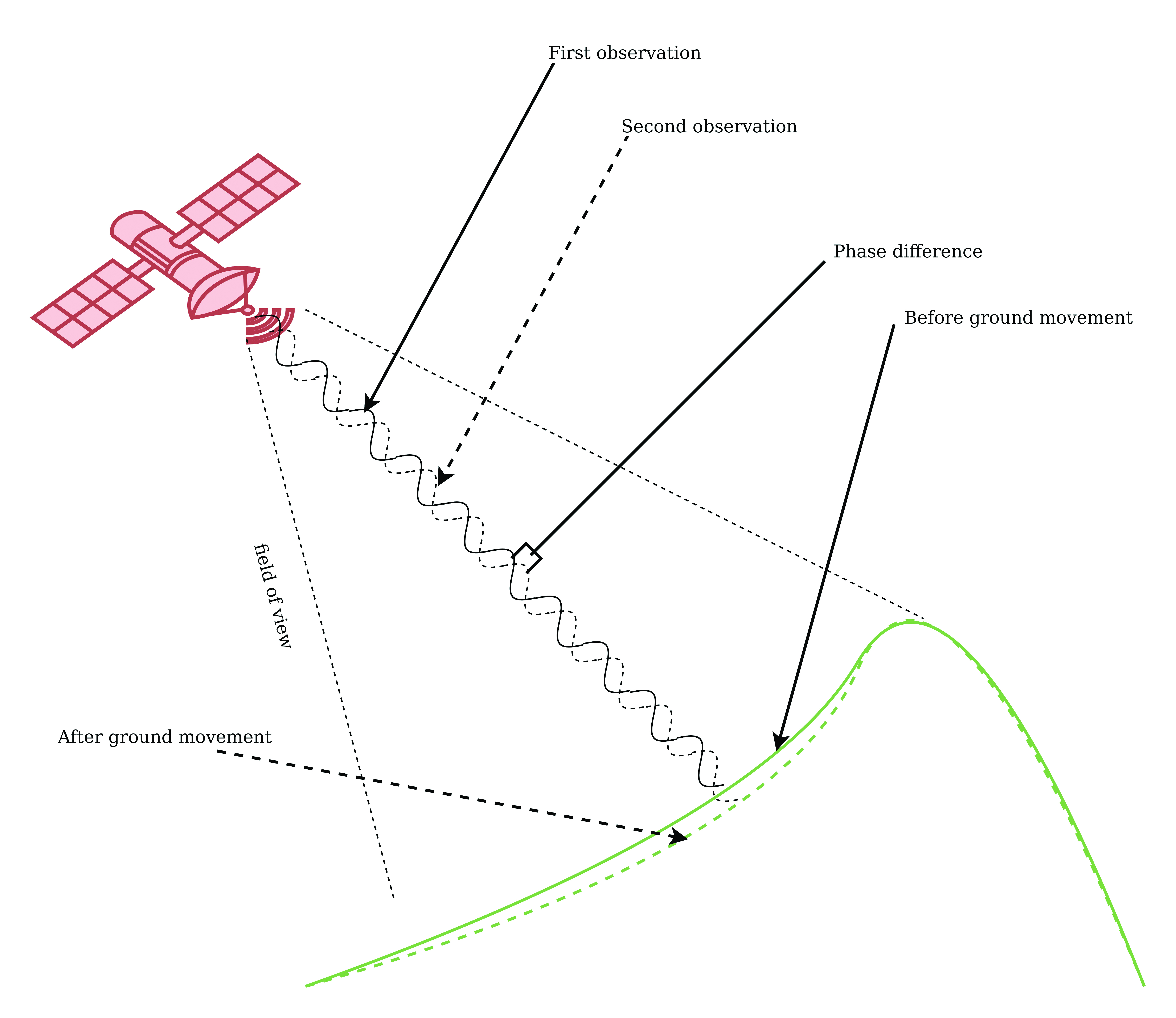
Figure 1. Phase shift in InSAR observations due to ground movement. (Image: Simon Ndiritu)
In differential InSAR, two images of the same location that are recorded at different times are used. If a surface movement has occurred between the first and the second acquisition, a phase shift is observed (Figure 1). The presence of interference fringes on an interferogram is an indicator of a phase shift and these fringes are summed during processing to provide a relative value of the phase change.
Ground-based SAR (GBSAR) employs the synthetic aperture radar technique to capture high-resolution images of the electromagnetic reflectivity of a target. This remote-sensing system is commonly used for monitoring civil infrastructure, buildings, mines, landslides, glaciers and more. While spaceborne SAR is capable of surveying large areas and records data over long periods of time, usually several weeks or months, GBSAR is suitable for monitoring small areas and has short sampling periods, usually a few minutes. In most surveying applications, the two remote-monitoring techniques are used together in a complementary fashion to enhance the overall performance.
The all-weather monitoring capability of satellite-based SAR makes it a popular tool for natural disaster management. Since the launch of the first SAR satellite in 1991, this technology has provided many emergency response teams with important insights on manmade and natural hazards. SAR data can be used to study different aspects of long-term behaviors of slow-moving surfaces, which is critical for planning emergency response to natural hazards such as volcanic eruptions, landslides and avalanches. SAR satellites orbit Earth at altitudes of between 500 km and 800 km and operate in the C-band (5 GHz to 6 GHz), X-band (8 GHz to 12 GHz) and L-band (1 GHz to 2 GHz). The temporal resolution of these satellites is mainly determined by their revisit periods.
Software-Defined Radio Platforms
A typical SDR platform features a radio front end (RFE) and a digital back end, with the RFE performing receive (Rx) and transmit (Tx) functions and offering a wide tuning range, typically 0 GHz to 18 GHz. This range is acceptable for widely used bands in SAR applications, including L-band, C-band and X-band.
The digital back end of a high-performance SDR system features a field programmable gate array (FPGA). This FPGA offers a variety of digital signal processing (DSP) capabilities, including upconverting, downconverting, modulation and demodulation. In addition, an SDR platform offers multiple transmit and receive channels, making it suitable for implementing multi-in multi-out (MIMO) radar systems.
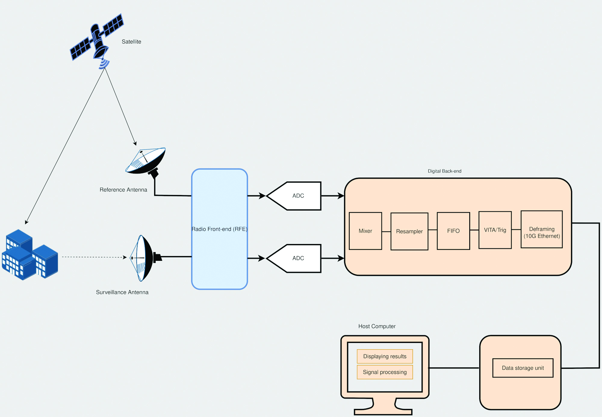
The architecture of SDR platforms allows them to integrate easily with a wide range of complex systems, such as SAR systems. The reconfigurability of SDRs allows upgrades and updates to be implemented without modifying the existing hardware, and can be designed to meet the size, weight and power (SWaP) requirements of an application. These features make SDRs suitable for implementing custom SAR monitoring solutions in small and large ground stations (Figure 2).
Figure 2. A simplified diagram of an SDR-based SAR system is shown, which employs a mobile-transmitter fixed-receiver passive bistatic SAR (MF-PB-SAR) architecture. (Image: Simon Ndiritu)
Integrating SDRs with SAR
A software-defined radar (SDRadar) is an SDR-based radar system that offers high flexibility and robustness. Compared to conventional radar, SDRadar offers many benefits, including the opportunity to reuse hardware, develop multi-function radar solutions, achieve faster development cycles, and have easier implementation of updates and new algorithms.
Tests with prototype SDR-based GBSAR systems have revealed the strong potential of SDR-based implementations. The MIMO architecture of an SDR platform allows realization of complex multi-frequency GBSAR systems uniquely suited for measuring displacement and other geophysical characteristics of landforms. SDR-based GBSAR systems can operate in different frequency bands and offer unmatched flexibility when it comes to signal generation and digital signal processing.
Many prototypes of airborne/satellite SAR systems based on SDR platforms have been implemented and their performance evaluated. Results have shown that they can offer better performance compared to conventional implementations. The use of multiple independent channels by SDR platforms allows the realization of compact and power-efficient multimode SAR systems, while the architecture of an SDR platform allows complex signal processing techniques such as digital beamforming (DBF), null steering and direction of arrival estimation to be implemented on FPGA.
Benefits of Integrating SDRs with SAR Solutions
Integrating SDRs into SAR systems provides many benefits. The MIMO architecture of SDR systems provides more channels than are required for SAR functions. The extra channels can be used for other applications such as satellite communications during emergencies. The wide frequency-tuning range of an SDR system allows the realization of a multi-function system with applications using different frequency bands. The reconfigurability of SDR platforms allows them to be repurposed for other applications. In addition, this reconfigurability enhances reusability, scalability and power efficiency. The low-latency FPGAs in high-performance SDR systems allow the realization of ultra-high-speed DSP algorithms for use in image processing and DBF.
Conclusion
The reconfigurability and impressive performance features of SDR platforms make them ideal for implementing scalable and flexible SAR monitoring systems for measuring land changes. The wide tuning range and MIMO architecture of SDR devices allows realization of a multi-function and multi-frequency system using a single device. In addition, the reconfigurability of SDR devices allows hardware reuse and low-cost implementation of updates and new algorithms.
Brendon McHugh is the field application engineer and technical writer at Per Vices. He possesses a degree in theoretical and mathematical physics from the University of Toronto.
Simon Ndiritu is an independent technical writer for Per Vices with a background in electrical and electronic engineer with a wealth of experience in designing hardware and firmware. He also has a passion for writing.
A roundup of recent products in the GNSS and inertial positioning industry from the March 2023 issue of GPS World magazine.
UAV
Image: InfiniDome
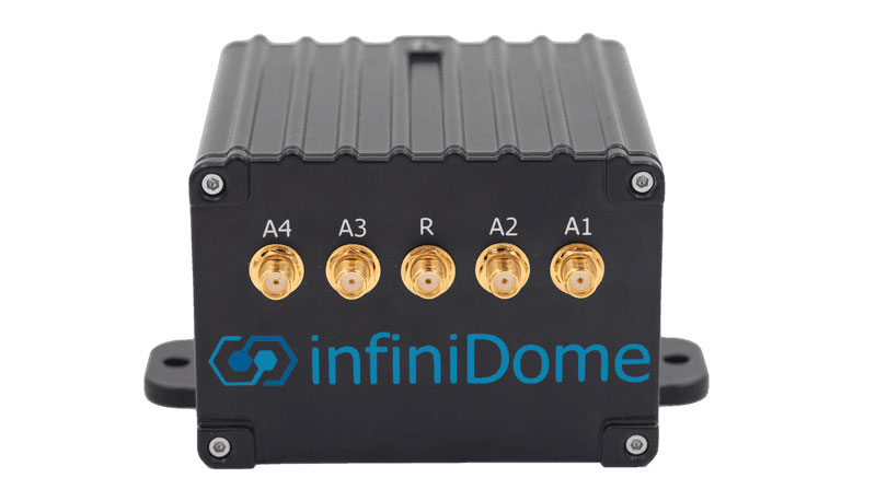
Anti-Jamming Device Provides protection from three directions of attack
The GPSdome 2 is tailored to defend small- to medium-sized tactical UAVs as well as manned and unmanned ground vehicles. With a small form factor (500 g, 87 mm x 91 mm x 61.55 mm) and minimal power consumption, GPSdome 2 is suitable for loitering munitions as well as UAVs. Fully retrofit and completely standalone, the system is compatible with almost any off-the-shelf GNSS receiver as well as standard active GNSS antennas, meaning that it can be integrated into existing GPS systems or into new product lines, manned or unmanned. With sophisticated algorithms and a proprietary RFIC, GPSdome 2 analyzes RF interference in the environment and combines multiple antenna patterns to create and dynamically steer three nulls in the direction of any hostile signal. GPSdome 2 provides simultaneous dual-frequency protection (GPS L1 + L2 or GPS L1 + GLONASS G1), creating up to three nulls, protecting from three jamming directions within each band in real time, making it suitable for PNT applications. The GPSdome 2 is a dual-use, non-ITAR device and comes with optional mil-spec compliance. InfiniDome, infinidome.com
Image: uAvionix
Command and Control Designed for easy integration
The SkyLine C2 management platform and muLTElink airborne radio systems (ARS) are designed to integrate, which enables a self-healing command-and-control network capable of both path and link diversity. This eliminates lost-link possibilities over broad terrain and altitude ranges. MuLTElink ARS consists of two models — muLTElink915 and muLTElink5060, the core of the uAvionix C2 system. The muLTElink915 model combines globally licensed aviation LTE, enhanced with frequency hopping 902 MHz – 928 MHz industrial, scientific and medical frequencies capability. The muLTElink5060 model combines global LTE with aviation-protected 5,030 MHz – 5,091 MHz C-band. Each muLTElink model allows up to one external CNPC radio to be optionally connected to allow simultaneous use of all three frequency ranges, higher power C-band operation or future radio integrations. uAvionix, uAvionix.com
Image: Atmos
VTOL UAV With Sony a7R mark III and IV camera
Atmos has integrated the Sony a7R mark III and IV cameras into its vertical take-off and landing (VTOL) fixed-wing UAV, the Marlyn Cobalt. This will increase coverage and accuracy achieved in a single flight for surveyors. Both cameras have an ISO of 32,000, which is expandable to 102,400, and camera sensors with high megapixel count — 42,4 MP for the a7R III and 61 MP for the a7R IV. When combined with Zeiss’ 35 mm and 21 mm lenses, it enables UAV surveyors to achieve ground sample distance levels below one 1 cm. The integration of the two cameras enables Marlyn Cobalt users to map an area of 210 ha with centimeter-level accuracy in a single flight. Atmos, atmosuav.com
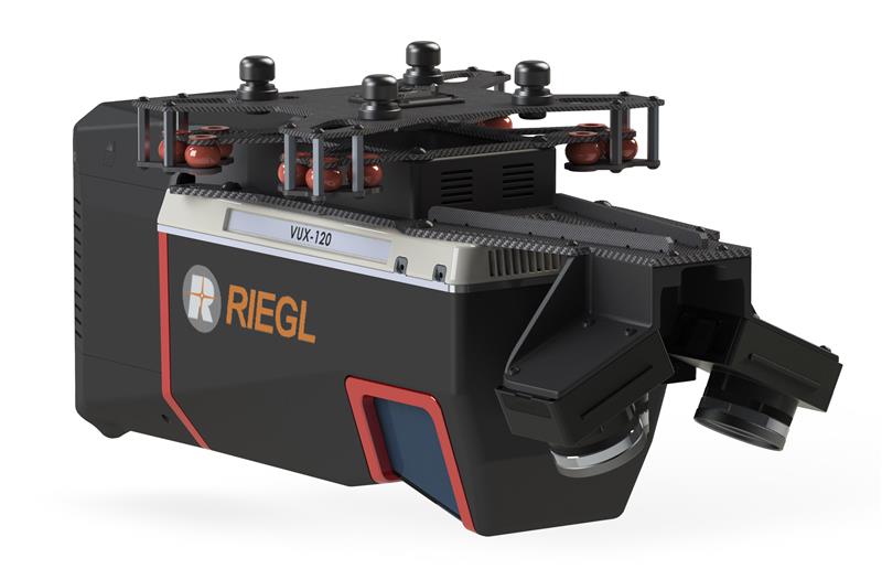
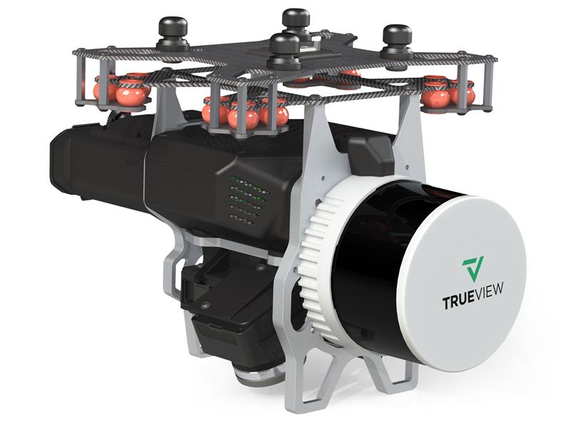
UAV and Lidar Systems Suitable for geospatial professionals
TrueView 535 consists of updated lidar sensors, adding a third return, increasing mapping abilities below canopy. An additional third nadir camera offers another point of view and improves photogrammetry quality. It also includes a longer, usable lidar range to increase flexibility. TrueView 720 is a fourth-generation Riegl VUX-120 with three laser beam orientations. It provides high-point density corridor mapping. Using the Riegl VUX-120 with three laser beam orientations (nadir, +10 degrees forward and –10 degrees backward) and three oblique/nadir cameras enables data collection from more surfaces in one flight path. One application of TrueView 720 is scanning power lines. Users can capture the poles vertically, front and back. The extreme range of this system means it can be integrated with UAVs, airplanes or helicopters. In addition to the two sensor payloads, GeoCue has launched its LP360 software add-on for processing and visualization — the 3D Accuracy and the Accuracy Star hardware.
GeoCue, geocue.com
OEM
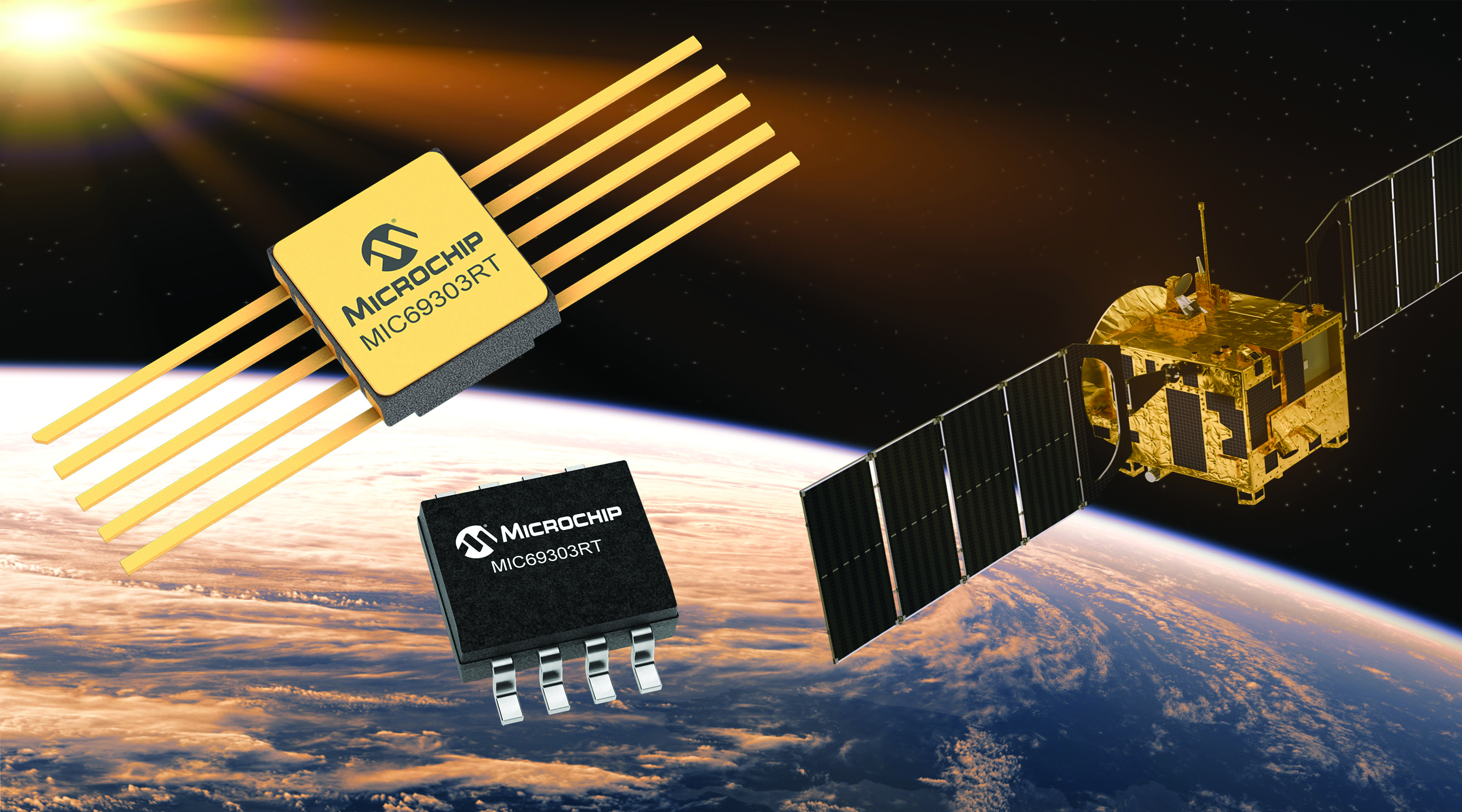
Image: Microchip
Voltage Regulator Device for LEO space application
The MIC69303RT is a radiation-tolerant power management device for space application developers. It is a high-current, low-voltage device targeting low-Earth orbit space applications. The MIC69303RT operates from a single low-voltage supply of 1.65 v to 5.5 v and can supply output voltages as low as 0.5 v at high currents. It offers high-precision and low dropout voltages of 500 mv under extreme conditions. The MIC69303RT is a companion power source solution for microcontrollers, such as the SAM71Q21RT and PolarFire field-programmable gate arrays. MIC69303RT is designed for harsh aerospace applications and remains operational in temperature ranges from -55 C to +125 C. Microchip Technology, microchip.com
Image: Spirent Communications
LEO Satellite Device Designed for GNSS/PNT lab testing
SimORBIT is a low-Earth-orbit (LEO) satellite solution software designed to aid developers in determining LEO orbits more accurately for GNSS/PNT lab testing. The software replicates LEO orbits so that simulations can provide the realistic environment of a LEO satellite, including gravitational and atmospheric impacts the satellite could encounter in space. Developers can create non-ICD signals via I/Q injection, or by the “Flex” feature, generating space-centered PNT signals to be developed in the lab as realistically as possible. Spirent Communications developed SimORBIT in partnership with SpacePNT. Spirent Communications, spirent.com
Image: Sony
5G Chipset Includes GNSS
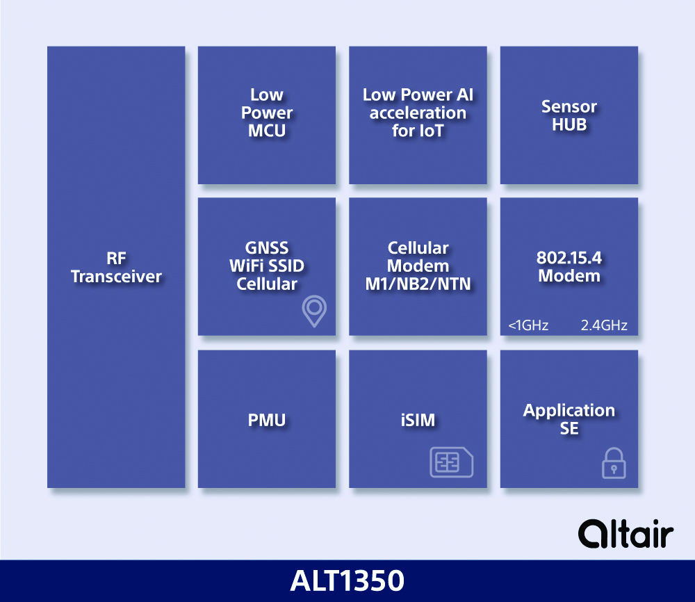
The ALT1350 implements GNSS, cellular and Wi-Fi-based location in a single chipset. The cellular LTE-M/NB-IoT chipset is designed to enable additional low-power, wide-area (LPWA) communication protocols; intermittent LTE and GNSS (GPS/GLONASS) navigation for low-cost applications; and concurrent LTE and L1/L5 GNSS for tracking applications. The ALT1350 incorporates a sensor hub to collect data from the sensors while maintaining ultra-low power consumption. It also provides cellular and Wi-Fi-based positioning and is tightly integrated to provide power-optimized concurrent LTE and GNSS to accommodate various tracking applications, which can be demanding with a single chip. The chip is designed to enable deployments for the internet of things (IoT), including location technologies. Sony, altair.sony-semicon.com
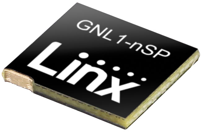
The ANT-GNL1-nSP is a surface-mount embedded GNSS antenna supporting GPS, Galileo, GLONASS, BeiDou and QZSS in the L1/E1/B1 bands. The ANT-GNL1-nSP antenna exhibits high performance in a compact size (10 mm x 8 mm x 1 mm) and features linear polarization and an omnidirectional radiation pattern. The antenna is available in tape and reel packaging and is designed for reflow-solder mounting directly to a printed circuit board for high-volume applications. Linx Technologies, linxtechnologies.com
Image: OriginGPS
GNSS Module Based on a MediaTek chipset
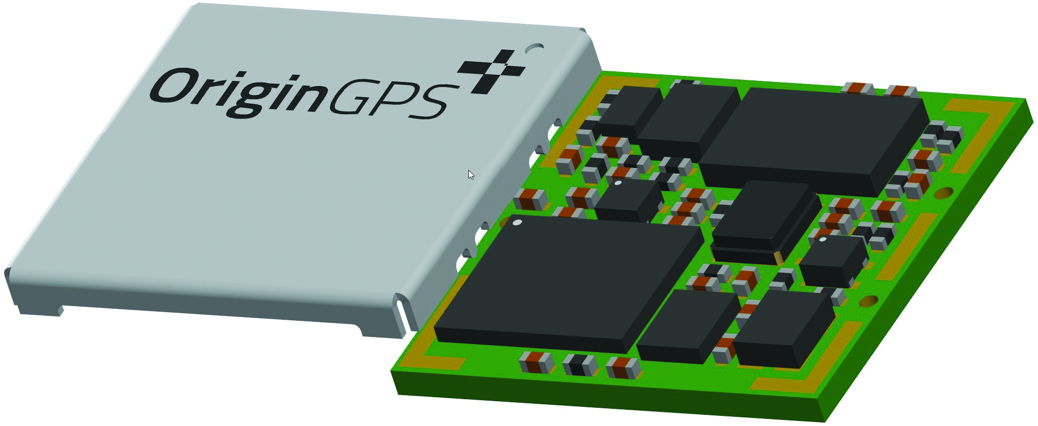
The ORG4600-MK01 dual-frequency module provides higher precision than the company’s previous modules. It has sub-1 m precision at a cost lower than that of the company’s first L1+L5 module, the ORG4600-B01, which is based on Broadcom’s chipset. The 10 mm x 10 mm ORG4600-MK01 was designed for applications deployed in challenging environmental conditions. The solution also includes RTCM, a logger and accurate orbit prediction. OriginGPS, origingps.com
MAPPING
Image: Mapbox
Navigation Software Includes enhancements to existing software and more
Navigation software development kit version 2.9 provides pre-built applications compatible with Android and IOS. SDK v2.9 provides the primary navigation components across a workflow using lines of code instead of starting from square one. The drop-in user interface is customizable to reflect a developer’s brand, obviating the need to manually develop a full end-to-end application. Navigation SDK Copilot — a backend analytics tool for CX on navigation applications — collects trace files of navigation sessions and search analytics data from users. Developers can use this data to gather feedback and collective user data to create touch points with users and improve application experience based on their data-drawn conclusions. Matrix API has been updated to support scheduled departure times and provide optimal driving routes, creating a more accurate estimated time of arrival. Mapbox, mapbox.com
Image: Hexagon
Defense Platform For developing Android applications
LuciadCPillar is designed for the development of mobile applications for dismounted soldiers in the field. Developers can build applications with 2D and 3D views. It features military symbology and supports many geospatial data types including vector data, raster data, elevation data, point clouds and 3D meshes. It has the same capabilities found in desktops, in-vehicle and browser applications built with LuciadLightspeed, LuciadCPillar and LuciadRIA. The platform offers capabilities to match high-resolution screens, graphic processing units and multi-core processors including the ability to display 3D data in mobile applications. LuciadCPillar supports ARM processors and an application programming interface, which aligns with the Android developer experience. Impact, a French system integrator, partnered with Hexagon to test LuciadCPillar and will integrate it into its Delta Suite product, which is used by the French Special Operations Command. LuciadCPillar is part of Luciad 2022.1, which is available now globally. Hexagon, hexagon.com
Image: Golden Software
Surface Mapping Designed for 3D surface mapping
The Surfer package is designed for 3D surface mapping and provides robust subsurface visualization and modeling functionality by incorporating many true 3D gridding and visualization tools. With the enhanced functionality, users can now model an additional variable, a C variable, such as a contaminant or chemical concentration, along with the traditional X, Y, Z values. Surfer also includes the ability to create a 2D map of a slice-through 3D grid, which users can move up and down through the grid, illustrating how the C value changes with depth. Part of Surfer’s enhancements is isosurface creation, enabling visualization of the 3D grid in the 3D view as an isosurface, providing another way to see how C data varies with depth or elevation. The new 3D-rendered volume functionality also allows users to visualize the 3D grid in the 3D view as a solid body by assigning colors to different C values, highlighting variations in the data. Golden Software, goldensoftware.com
Industry experts noted in our November 2022 issue that heavy equipment autonomy may be a distant future. However, the steady innovation in machine-control technology to get there is yielding substantial value. To drill deeper into those technologies, we interviewed additional industry experts with a focus on the key role of GNSS in such systems.
1D, 2D and 3D
There is currently a sharp growth in the adoption of 3D systems, according to Jordan Van Wie, product specialist with SANY America, a prominent manufacturer of construction equipment. “The fact is that many jobs are requiring this. They’re more efficient in their bidding process. They know exactly where they need to cut and where to fill — this means being more productive in less time.”
SANY America is based in Peachtree City, Georgia, where many of its construction equipment systems are manufactured, including the SY225C, a popular medium excavator.
The process of automating to the levels the operators desire is a matter of which sensors are added and how they sense the active geometry of the equipment in use.
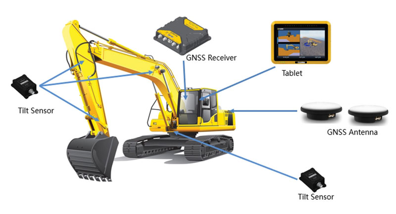
For an excavator, SANY installs four sensors, then measures the machine, said Mukesh Selvaraj, product manager, medium and large excavators, SANY America.
“We know the distance between the bucket pin and the stick pin, up through the boom, and the angles on the sensors. We can compute in the system and report where the tip of the bucket is in relation to the body, and construct a 3D model in real time. This reporting can be as fast as 200 Hz.”
Among the machine-control systems implemented on SANY construction equipment are those from Hexagon | Leica Geosystems. Leica produces precision guidance and control sensors and systems for construction, agriculture and mining that are integrated onto various heavy equipment brands.
While 3D is becoming more popular, systems need to be scalable. Hexagon | Leica Geosystems has variants for different levels of guidance and automation, said Kert Parker, U.S. channel development manager for the company.
“For instance, if you start with our PowerDigger Lite, it has a control box, a display, a boom sensor, an angle sensor for the stick (which includes a laser catcher) and a 360° bucket sensor. This lets you know where the bucket tip is in relation to the model — call it a 1D system.” The cost of such a system might only be 5% or 10% of the cost of the machine on which it is installed — a modest investment for the productivity gains it can deliver.
To upgrade and run automatics, users could add a machine control panel and docking station with just 2D software. “That will give you a semi-automatic solution even on 2D. Then you can upgrade and add the GNSS receiver and antenna — or antennas — and 3D software to make it 3D, semi-automatic,” Parker said.
Two-thirds of the price of the base system is for the sensors on the boom, stick, bucket, the pitch and roll sensor, and the wires that communicate throughout the system, Parker explained.
“So, it’s completely scalable. You can start with a low-cost system upgrade to do GNSS fully and semi-automatic. We can automate any pilot-controlled machine, then we set the pressure. And when we sense the stick pressure, if the system is going automatic, then we automate the boom and the bucket.”
Third ‘D’ Options
“When you’re using something to give the machine a northing, an easting and a height at all times — that is when it becomes full 3D,” Parker said.
3D systems can be configured with a single GNSS receiver, with dual GNSS receivers, or off of a robotic total station. “The only difference between single and dual is that, with single, every time you move the machine you have to do a calibration swing, about 90° to get your heading again.”
“You can dig curves and complex designs working in 2D,” Van Wie said. “But every time you move the machine, you have to re-bench to a known reference, either by pinching with a bucket’s teeth, or hit the stick sensor that has an incorporated laser catcher. When you move the machine, you catch the laser beam again, and you use that for your known reference to dig back from the 3D model.”
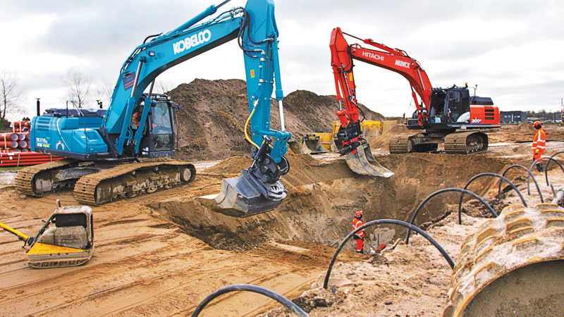
Excavators are a high-growth class of heavy equipment for machine-control adoption, with many excavators ready for system integration. Shown here, Leica iCON iXe3 systems on a Kobelco SK210 (left) and Hitachi 300-02 (right). (Image: Hexagon | Leica Geosystems)
For certain operations — such as excavating in a straight line or moving materials to the side —higher levels of automation may not be needed, so some users appreciate the option of starting with a cheaper system.
“For the small operator, of course, but even for a large operator, it’s a big investment to go full 3D,” Van Wie said. “They don’t want to go full 3D right away, or not on all equipment at once. They start off with just the basics and get familiar with it. Then when they want to upgrade, they have some of the stuff that they’re going to need for their machine already on it.”
System Examples
eSurvey GNSS manufactures GNSS-based equipment, software and systems for surveying, mapping, agriculture, UAV and construction. Better known in other global markets than in North America, the company has seen a steady rise in the market for construction automation — outpacing other sectors utilizing heavy equipment automation such as agriculture and mining combined. For construction, in many parts of the world excavators are the prime focus for automation.
Figure 1. A common configuration of sensors for excavators: GNSS receiver, dual antennas, control tablet and tilt sensors on the body, boom, stick and bucket.(Image: eSurvey GNSS)
Their eME10 system for excavators includes a dual-antenna GNSS receiver, three single-axis tilt sensors, one dual-axis tilt sensor, a tablet and software (Figure 1). “The eME10 does not support a rotating bucket at this time,” said Edward Zhang, product manager for machine control technology. “We support standard excavators, excavators that reach into the water (for instance on dredging barges), and with different bucket tools such as quartering hammers and milling tools.”
Another popular system for compactors is the eMC10, with a single-antenna GNSS receiver, tablet and software, and optional temperature and vibration sensors.
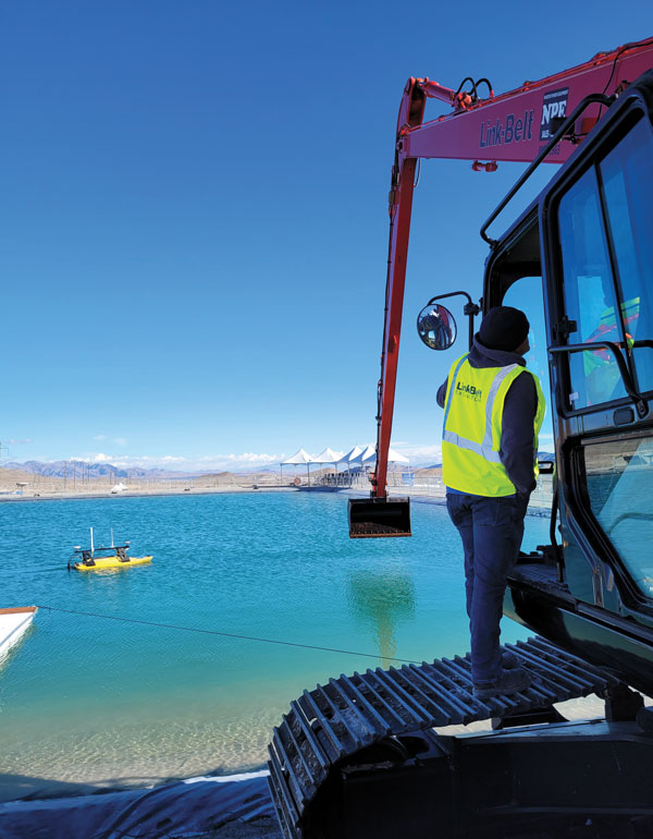
Managing Positioning
Both the excavator and hydro survey boT have dual GNSS antennas for position and orientation, ensuring fidelity between the 3D model and operation of the excavator for dredging. (Image: Gavin Schrock)
High-precision GNSS, as implemented for architecture, engineering and construction (AEC) applications, can yield centimeter-grade results. However, as many AEC professionals and practitioners know, achieving repeatable and consistent results requires an experienced and skilled GNSS operator. Is the operator examining the results for statistical consistency? How have the observations been constrained to the desired reference framework? Have sources of error such as multipath and space weather been considered?
However, Nick Fifarek, general manager at SITECH Pacific LLC, a construction technology provider, said that equipment operators only need to learn the user interface.
“They are mostly concerned with how the grade is shown in the model, and what actions are required to meet the grade. They should not need to be concerned with the working of the GNSS receiver.”
A larger firm with multiple systems will usually have a technician or surveyor on board, Fifarek explained. This expert would have the experience needed to set up a GNSS site base, ensure corrections are received, and troubleshoot causes of anomalies and poor results.
To be efficient, an operator should not have to deal with a complex set-up.
“It should be more like Google maps in your car,” Fifarek said. “They do not need to know how the model was created, and how the GNSS delivers positions to the interface. All the sensors should work seamlessly, like tilt sensor and IMUs [inertial measurement units] and how they work together with the GNSS to put positions on the blade or bucket. Once this is all working well and the model is applied, they should just be able to take directions.”
Nevertheless, sometimes this expert will need coaching, or a small firm may not have an expert at hand.
“We may need to teach them about some fundamentals, such as signal-to-noise ratio, PDOP [positional dilution of precision], and other quality indicators — especially when setting up the site base station,” Fifarek said.
Additionally, he pointed out, the control must be set up — this is mostly done by engineering or surveying firms along with site calibrations — and operators need to know how to check it.
Multipath Issues. Fifarek has not experienced problems with short masts for GNSS antennas, saying that the height of the cab is sufficient. Modern multi-constellation receivers, have improved multipath mitigation, and are able to work in sites with limited sky view or obstructions. Equipment such as excavators and dozers typically have dual-antenna GNSS systems, or two receivers and antennas. This provides not only position, but orientation and heading. These are usually installed on the body or cab, although some systems have a GNSS antenna on each end of the blade. Some systems use a method that only fixes one of the antennas/receivers, and then performs a fixed baseline solution for orientation.
The Chain of Components
Much like autonomy in vehicles, machine control implementation can be defined as various levels.
Level 1: GNSS-assisted guidance. The most basic level of implementation provides the equipment’s location and heading. It acts the same way as a navigation device or phone in your car. The technology has been around for decades for precision agriculture and construction. Level 2: Implement Control. Control of the blade or bucket. Level 3: Assist. Implement control plus a level of automation where the operator moves the control stick to initiate an action the machine completes by moving the blade or bucket to meet the design model geometry. This can include steering for various types of equipment. Level 4: Autonomy. More on that later.
The power of tilt-compensated GNSS+IMU smart antennas may be the key to reducing the number and complexity of synchronizing a “chain of sensors.” In this example, a Trimble R780 smart antenna has been added to the stick of an excavator. (Image: Trimble)
For levels 2 through 4, continuously updating a position on the blade or bucket requires a chain of sensors to work in tightly controlled harmony. An excavator could be equipped with one or two GNSS receivers and antennas and a tilt sensor on the body, explained Geoffrey Kirk, product manager, autonomy and assist for Trimble. The GNSS will provide the position and orientation of the body, or rotating section of the body, on an excavator, and the tilt sensor reads how level it is. Another option is positioning with a total station and prism on the body, such as when GNSS is not available. “Either way, you need to know where you are in 3D space to be able to work on any 3D model,” Kirk said. “Today there are usually about 30 satellites in view. We can do so much more now compared to the days when we had fewer satellites, things that would have been impractical,” Kirk continued.
Sensors on the boom, stick and bucket can be likened to an upper arm (boom), forearm (stick) and hand (bucket), with rotating buckets acting like a wrist.
“We put a six-degrees-of-freedom IMU at each of these locations,” Kirk said. This is a chain of highly dependent geometry extended out to the bucket. However, Kirk said there may be a better way.
Reducing the Links
In recent years, a new technology has been implemented for GNSS smart antennas (rovers), like those that surveyors and grade checkers use, which tightly couples IMUs and movement of the GNSS antenna for calibration-free tilt compensation. Examples include the Trimble R12i (for surveying) and R780 (for construction), Leica GS19 T, and many more — few high-precision rovers made today lack tilt compensation. The observed acceleration and direction of the antenna adds orientation to the tilt angle (from the onboard tilt sensors), so the position of the tip of the survey rod can be computed precisely and in real time.
At the Bauma construction trade fair held in November 2022 in Munich, Germany, Trimble gave participants a peek at something new: putting a tilt-compensating GNSS smart antenna out on the stick of an excavator.
“With current systems, every time you hit one of those joints on an excavator, you need to understand what it is doing, calculating angles along the way,” Kirk said. “By mounting a tilt-compensated GNSS receiver on the stick, this becomes a lot easier to do.” Such innovations dovetail well with another trend in construction equipment: a move from purely hydraulic steering to drive-by-wire. This trend makes for more simplified and often less costly processes for adding implement control and automatics, but may also be key in implementing autonomy.
The Path Toward Automation
“One of the big changes in the industry is understanding what tasks operators are trying to do, so that we can help them do those tasks,” said Kirk. “We want to help people be more productive. We know autonomy is a thing. We’re actively working on autonomy; it’s going to be a while. In the interim, we want to make sure that we are providing value to the manual operators for the tasks that we can’t do autonomously.”
Key foundational components of what would go into autonomous systems are already in place.
“With automatics, you already have implement control, and in some implementations, you even have steering,” Kirk said. “What is missing in terms of the mechanics is speed control — that may be the easy part.” Adding the crucial situational awareness, other sensors for feedback, and the brains for automation is what might take a lot of time to work out.
“Autonomy for cars is where you are trying to avoid hitting things,” said Kirk. “For construction, we are in the business of hitting piles of dirt and spreading them around.” For a car, the sensors see something, recognize it, know how far away it is, and can issue such commands as “stop” or “slow down” — which is not so simple for construction.
Three key technologies you’ll see being used for situational awareness are radars, cameras and lidar, mostly used in combination. “Radars have some really nice behaviors,” explained Kirk, but cautioned that they cannot tell what they are doing.
A demonstration implementation of an autonomous excavator.(Image: Trimble)
For instance, adaptive cruise control in cars, which is nearly always done with radar, works very well and reliably. Most such radars are now solid state and safety certified. Unfortunately, he points out, while radar is very good at alerting drivers that there is something in front of them, it is not very good at telling them what it is.
“That’s why developers put in cameras, so that you can see whether what’s in front of you is a person, another vehicle, or something else. That’s why you have those combinations of sensors.”
One of the reasons it will take longer to automate construction, Kirk explained, is that operators need to know much more about the nature of other objects in the construction environment than cars do on the road. The operators need to know not only what people, equipment and materials are around them, but also whether there is something or someone standing in front or on top of the pile of dirt.
“For situational awareness, you need to be able to do real-time mapping,” Kirk said. “Lidar and cameras, such as stereographic cameras, can be used as classifiers. Lidar can have limitations, such as when driving directly into the sun.”
“The smarts for autonomy are knowing what the task is and how to perform that task,” Kirk said. “However, from the standpoint of a machine’s sensor and setup, we’re not controlling speed, though we do on agricultural machines. So, machines are matched really well for autonomy — you can make them do whatever you want today.”
Examples of autonomous conduction systems were demonstrated in the off-site “sandbox” exhibit of Trimble Dimensions+ held in November 2002 in Las Vegas. There was an autonomous excavator, a compactor and a remote-control dozer.
Yet these were operating in a controlled environment. Kirk said that for safety reasons, early adoptions of autonomy might be confined to sites that are not along roads and highways.
Alex Murdaugh (Image: Pool reporter photo from trial)
Cellphone and vehicle location data is at center stage as former South Carolina attorney, Alex Murdaugh, takes the stand in the trial for the murder of his wife, Maggie Murdaugh, and son, Paul Murdaugh. Troves of data including call logs, text messages, steps recorded, app information, coordinates determined by GPS and more from Alex, Paul and Maggie, are being retrieved for the ongoing trial.
Records retrieved from Murdaugh’s cellphone show that after the murders occurred, he proceeded to Google an area restaurant, check group messages, and made other calls that night, which he testified were accidental, according to CNN reports. Vehicle location data was also pulled and presented at trial to identify a timeline of events for the court, according to reports from AP.
Location data retrieved from Murdaugh’s cellphone on the night of the double murders is not the only time this type of data comes into play for the Murdaugh family.
In February 2019, Paul Murdaugh and his friends were involved in a boating accident, which killed one of the boaters, Mallory Beach. In the new Netflix documentary regarding the Murdaugh family, Murdaugh Murders: A Southern Scandal, a relative of one of the boaters mentions in Episode 2 that Beach always wore an Apple Watch, and asked why investigators failed to look into location data to find her sooner.
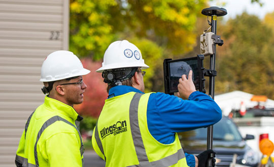
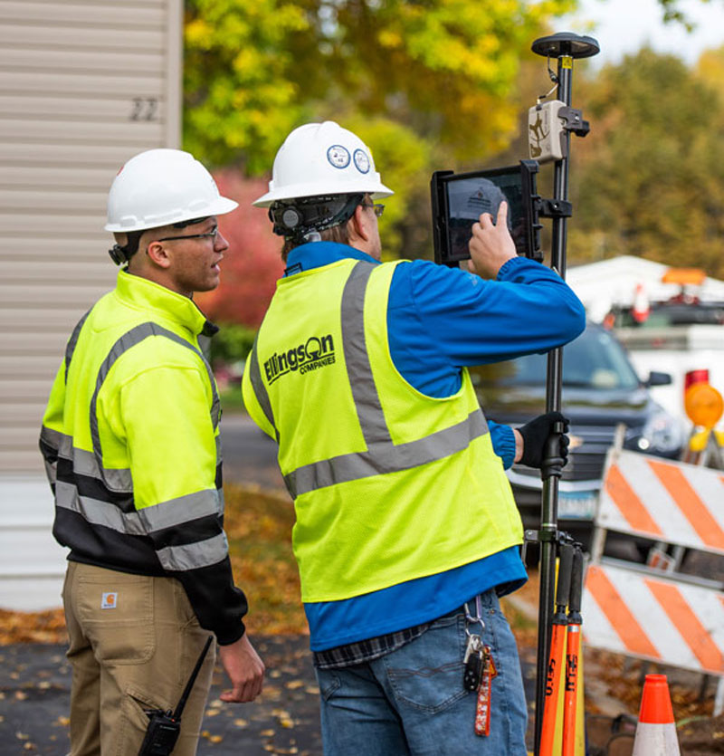
Surveying is both an ancient profession and one of today’s most technologically advanced. Surveyors are among the first on the site of a new construction project, staking out its corners and boundaries, and mapping elevation contours, as well as among the last, surveying the project “as built.” This is particularly important for features that will no longer be visible once the project is complete, such as underground utilities.
While many surveyors work in quiet, uncrowded environments — such as surveying the boundaries of farm fields — those who work on large construction projects operate among the hustle and bustle of bricklayers, carpenters, electricians, plumbers and other tradespeople, as well as cranes, backhoes and other heavy machines. This chaotic environment means that in addition to accuracy and efficiency, surveyors also are concerned with safety.
In the following cover story, a Minnesota-based construction company describes a new system it developed for surveying and mapping underground utilities. Also, professional surveyor Gavin Schrock discusses the benefits of a flexible approach to GNSS rover accuracy and of adding scanning capabilities to robotic total stations.
GMV is using high-resolution optical imagery as a part of emergency management efforts, to map the population and infrastructure of several cities in Turkiye after the 7.8 magnitude earthquake. The imagery of the aftermath is thanks to Europe’s Copernicus program, which keeps satellites and Earth observation services operational to support management and decision-making in different areas, particularly in the field of emergency management.
The satellite images show the challenge faced by rescue teams and reveal the massive amounts of destruction caused in cities across Turkiye and northern Syria. (Image: GMV)
GMV is one of the suppliers of Copernicus program infrastructure. GMV monitors the database architecture and ensures its integrity, analyzes the data required by the service chains, and identifies the most suitable technologies to keep the entire program operational.
GMV is working with the EU Civil Protection Mechanism’s Emergency Response Coordination Center to keep them updated on the ongoing emergency situation.
For more on the emergency satellite mapping, visit the Copernicus website.