Mojio, an open platform for connecting cars, has announced a partnership with Dooing, a new team management platform for businesses that can dispatch jobs and track teams.
“With Dooing, any business can dispatch jobs and track teams on the move, from three people to thousands,” said David Barton-Grimley, a Mojio developer and co-founder of Dooing. “iOS and Android apps are used to manage field staff, assigning and tracking a job’s life cycle from start to finish with reports on key performance metrics. Enterprises and startups alike can build Dooing into their own products with our API.”
With the partnership Mojio says businesses can narrow down on fuel consumption, prevent breakdowns with diagnostics insights and track in real time.
“Mojio is the first platform we’ve integrated into Dooing, enabling Mojio customers to track jobs with live fleet data,” Barton-Grimley said. “Additionally, we’ve added to the ability to track and report on key metrics like fuel consumption and distance traveled down to the specific job.”
Mojio, the only open-platform connected car device — according to the company — has plans to continue growing its ecosystems of drivers, partners and developers.
US Fleet Tracking‘s GPS trackers allow companies to monitor its fleet drivers’ speeds.
Monitoring a driver’s speed may reduce the risk of an increase in insurance premiums, ticket costs, and fuel and maintenance costs. The company’s GPS trackers store speeding information, meaning drivers may increase performance knowing their speed is being observed.
NetComm Wireless Limited and Vodafone have added the Vodafone MachineLink 3G Plus to the Integrated M2M Terminals range, offering an alternative for unconnected machines that need a larger selection of interface options. Developed by NetComm Wireless to facilitate the uptake of Machine-to-Machine (M2M) across a multitude of industries globally, the Vodafone MachineLink 3G Plus enables M2M connectivity in areas such as healthcare, agriculture, vending, point of payment and energy.
The Vodafone MachineLink 3G Plus is a 3G penta-band modem and router with built-in GPS. It is compatible with Vodafone or Vodafone M2M partner networks worldwide, and the Vodafone M2M Global Platform. The device supports multiple communication protocols and interface options with features including Ethernet, Serial (RS232/422/485), I/O and USB 2.0 ports. Designed for flexible customization, the Vodafone MachineLink 3G Plus features an embedded Software Development Kit (SDK) and open source Linux OS to support unique business functions.
Vodafone’s second annual M2M Adoption Barometer found that M2M adoption has grown more than 80%, with more than one-fifth of companies actively using the technology. The Vodafone MachineLink 3G Plus is expected to advance this growth by allowing businesses to upgrade from legacy serial connectivity to IP connectivity with access to a broader range of connection choices.
“The Vodafone MachineLink 3G Plus is the second bespoke product developed for Vodafone which gives businesses the ability to select the best solution for their individual applications. It presents a tremendous opportunity for businesses that need extra options to connect and manage valuable assets,” saidDavid Stewart, CEO and managing director, NetComm Wireless.
Centimeter Positioning with a Smartphone-Quality GNSS Antenna
By Kenneth M. Pesyna, Jr., Robert W. Heath, Jr. and Todd E. Humphreys, the University of Texas at Austin
The smartphone antenna’s poor multipath suppression and irregular gain pattern result in large time-correlated phase errors that significantly increase the time to integer ambiguity resolution as compared to even a low-quality stand-alone patch antenna. The time to integer resolution — and to a centimeter-accurate fix — is significantly reduced when more GNSS signals are tracked or when the smartphone experiences gentle wavelength-scale random motion.
GNSS chipsets are now ubiquitous in smartphones and tablets. Yet the underlying positioning accuracy of these consumer-grade GNSS receivers has stagnated over the past decade. The latest clock, orbit, and atmospheric models have improved ranging accuracy to a meter or so, leaving receiver-dependent multipath and front-end-noise-induced variations as the dominant sources of error in current consumer devices. Under good multipath conditions, 2-to-3-meter-accurate positioning is typical; under adverse multipath, accuracy degrades to 10 meters or worse.
Yet outside the mainstream of consumer GNSS receivers, centimeter — even millimeter — accurate GNSS receivers can be found. These high-precision receivers are used routinely in geodesy, agriculture, and surveying. Their exquisite accuracy results from replacing standard code-phase positioning techniques with carrier phase differential GNSS (CDGNSS) techniques. Currently, the primary impediment to performing CDGNSS positioning on smartphones lies not in the commodity GNSS chipset, which actually outperforms survey-grade chipsets in some respects, but in the antenna, whose chief failing is its poor multipath suppression. Multipath, caused by direct signals reflecting off the ground and nearby objects, induces centimeter-level phase measurement errors, which, for static receivers, have decorrelation times of hundreds of seconds. The large size and strong time correlation of these errors significantly increases the initialization period — the so-called time-to-ambiguity-resolution (TAR) — of GNSS receivers employing CDGNSS to obtain centimeter-level positioning accuracy.
Prior work on centimeter-accurate positioning with low-cost mobile devices has focused on external devices, or “pucks,” which contain a GNSS antenna and chipset. These devices interface with the smartphone via Bluetooth or a wired connection. Such solutions, which enjoy the better sensitivity and multipath suppression offered by their comparatively large, high-quality GNSS antennas, do not provide insight into the feasibility of CDGNSS on a stand-alone smartphone platform.
This article demonstrates that centimeter-accurate CDGNSS positioning is indeed possible based on data sampled from a smartphone-quality GNSS antenna. This result has far-reaching significance for precise mass-market positioning. We offer an empirical analysis of the average gain and carrier phase multipath error susceptibility of smartphone-grade GNSS antennas. We also demonstrate that, for low-quality GNSS antennas such as those in smartphones, wavelength-scale random antenna motion substantially improves the time to integer ambiguity resolution.
This article focuses on single-frequency CDGNSS rather than multiple-frequency CDGNSS or other carrier-phase-based techniques, such as precise-point positioning (PPP), for three reasons. First, virtually all smartphones are equipped with single-frequency GNSS antennas tuned to the L1 band centered at 1575.42 MHz, and single-frequency CDGNSS will likely forever remain the cheapest option. Second, as compared to PPP, CDGNSS converges much faster to centimeter accuracy, which will be important for impatient smartphone users.
Finally, as centimeter-accurate GNSS moves into the mass market, GNSS reference stations will proliferate so that the vast majority of users can expect to be within a few kilometers of one. In this so-called short baseline regime, the differential ionospheric delay between the reference and mobile receivers becomes insignificant, obviating differential delay estimation via multi-frequency measurements. Of course, the additional signal measurements produced by multiple-frequency receivers would lead to faster convergence times and improved robustness, but for many applications, single-frequency measurements will be adequate.
Test Architecture
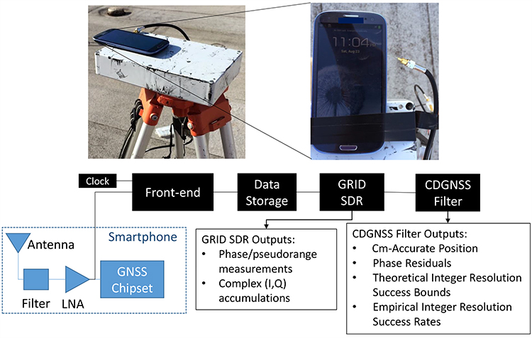
We used the test architecture shown in Figure 1 to collect data from a smartphone-grade antenna and higher quality antennas, process these data through a software-defined GNSS receiver, and compute a CDGNSS solution on the basis of the carrier phase measurements output by the GNSS receiver.
Figure 1. Test architecture designed for an in-situ study of a smartphone-grade GNSS antenna. The analog GNSS signal is tapped off after the phone’s internal bandpass filter and low-noise amplifier and is directed to a dedicated RF front-end for downconversion and digitization. Data are stored to file for subsequent post-processing by a software GNSS receiver and CDGNSS filter.
The architecture has been designed such that the antenna is left undisturbed within the phone; data are collected by tapping off the analog signal immediately after the phone’s internal bandpass filter and low-noise amplifier. This analog signal is directed to an external radio frequency (RF) front-end and GNSS receiver. Use of an external receiver permits well-defined GNSS signal processing unencumbered by the limitations of the phone’s internal chipset and clock.
The clock attached to the external front-end was an oven-controlled crystal oscillator (OCXO), which has much greater stability than the low-cost oscillators used to drive GNSS signal sampling within smartphones. However, it was found that reliable cycle-slip-free GNSS carrier tracking only required a 40-ms coherent integration (pre-detection) interval, which is within the coherence time of a low-cost temperature-compensated crystal oscillator (TCXO) at the GPS L1 frequency.
Although only a single model of smartphone was tested using this architecture — a popular mass-market phone — the results are assumed representative of all smartphones from the same manufacturer.
Using this architecture, many hours of raw high-rate (∼6 MHz) digitized intermediate frequency samples were collected and stored to disk for post processing. Also stored to disk were high-rate data from a survey-grade antenna, which served as the reference antenna for CDGNSS processing. An in-house software-defined GNSS receiver, known as GRID, was used to generate, from these samples, high-quality carrier phase measurements. GRID is a flexible receiver that can be easily adapted to maintain carrier lock despite severe fading. Complex baseband accumulations output from GRID allowed detailed analysis of the signal and tracking loop behavior to ensure that no cycle slips occurred. The generated carrier phase measurements were subsequently passed to a CDGNSS filter, a model for which is described in the next section.
CDGNSS Processing
The CDGNSS filter described in this section ingests double-differenced carrier phase measurements output from GRID and processes them to produce (1) the centimeter-accurate trajectory estimate of the mobile antenna, (2) a time history of phase residuals, (3) carrier phase integer ambiguity estimates, (4) theoretical integer ambiguity resolution success bounds, and (5) empirical integer ambiguity resolution success rates. These outputs are used to analyze the performance of the smartphone-grade antenna and compare its performance to higher-quality antennas.
CDGNSS Filter Model. The filter’s state has a real-valued component xk that models the mobile antenna’s relative center of motion, its instantaneous offset from this center of motion, and its velocity at each time epoch k:
. (1)
The filter’s state also has an integer-valued component that models the CDGNSS phase ambiguities:
(2)
where NSV is the total number of satellites tracked. Such integer ambiguities are inherent to carrier phase differential positioning techniques; their resolution has been the topic of much past research and is required to produce a CDGNSS positioning solution.
Dynamics and Measurement Models. The real-valued state component xk is assumed to evolve as a mean-reverting second-order Gauss-Markov process. This process models the time-correlated and mean-reverting motion a smartphone experiences when held or moved gently in the extended hand of an otherwise stationary user. The integer-valued state component nk is modeled as constant, since the phase ambiguities remain fixed so long as the receiver retains phase lock on each signal.
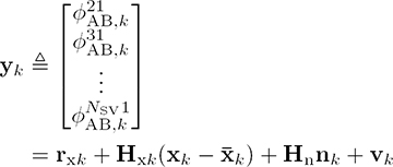
The filter ingests measurement vectors yk for k = 1, …, K, each populated with a single epoch of double-differenced carrier phase measurements for i = 1, 2, . . . , NSV–1. The filter’s measurement model relates yk to the real- and integer-valued state components through the following linearized GNSS carrier phase measurement model:
(3)
where rxk is a vector of double-differenced modeled ranges based on the filter’s real-valued state prior ,Hxk and Hn are the measurement sensitivity matrices for the real- and integer-valued state components, and vk is the double-differenced measurement noise vector, all at time k.
Phase Residuals. After processing data through the CDGNSS filter, the filter outputs, in addition to a time history of centimeter-accurate position estimates, a time history of phase residuals , which can be thought of as departures of each double-differenced phase measurement from phase alignment at the phase center of the antenna. These residuals can be modeled as
(4)
where rxk is now based on the filter’s real-valued state estimate at time k and represents the filter’s estimate of the integer ambiguities at time K.
Phase residuals have been produced for batches of data collected from four different grades of antennas, as described next. These residuals will be used to analyze the suitability of each antenna for CDGNSS positioning.
Antenna Performance Analysis
This section describes four antennas from which data were captured and processed using the test architecture and CDGNSS filter described previously. It also quantifies the characteristics that make low-quality smartphone-grade antennas poorly suited to CDGNSS.
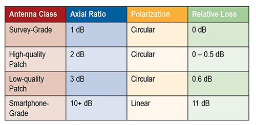
Table 1 describes a range of antenna grades of decreasing quality, noting properties relevant to CDGNSS. The loss numbers in the far-right column represent the average loss in gain relative to a survey-grade antenna, where the average is taken over elevation angles above 15 degrees.
Table 1. Antenna properties.
Survey-grade antennas, whose properties are described in the first row of Table 1, have a uniform quasi-hemispherical gain pattern, right-hand circular polarization, a stable phase center, and a low axial ratio. These are all desirable properties for CDGNSS. Unfortunately, these properties inhere in the antennas’ large size; the laws of physics dictate that smaller antennas will typically be worse in each property.
The last row of Table 1 lists the properties for a smartphone-grade antenna. As shown subsequently, this antenna loses between 5 and 15 dB in sensitivity as compared to the survey-grade antenna. Such a loss makes it difficult to retain lock on GNSS signals. In addition, this antenna’s linear polarization leads to extremely poor multipath suppression.
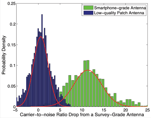
Antenna Gain Analysis.Figure 2 quantifies one of the obvious drawbacks of a smartphone-grade antenna, namely, its low gain.
Figure 2, Drop in carrier-to noise ratio, from 2 hours of data and 9 tracked satellites. Antennas remained stationary.
The rightmost histogram, in green, shows that the decrease in carrier to noise ratio as compared to a survey-grade antenna is on average 11 dB, such that the smartphone-grade antenna only captures approximately 8 percent of the signal power as compared its survey-grade counterpart. For comparison, shown on the left, in blue, is a histogram of the decrease in carrier-to-noise ratio for the low-quality patch antenna. This antenna only suffers about a 0.6-dB drop in power on average relative to the survey-grade antenna. Each histogram was generated from 2 hours of data with nine tracked satellites ranging in elevation from 15 to 90 degrees. The antennas remained stationary. The variation in signal power around the means is due to the multipath-induced power variations in the signal as well as to the different gain patterns between each antenna and the survey-grade antenna.
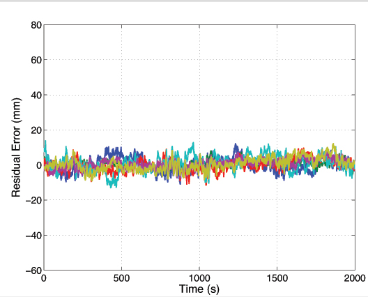
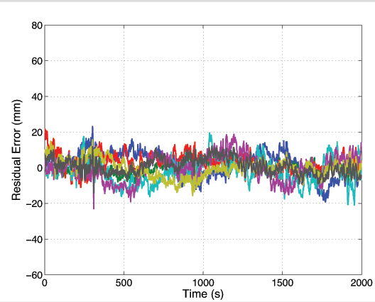
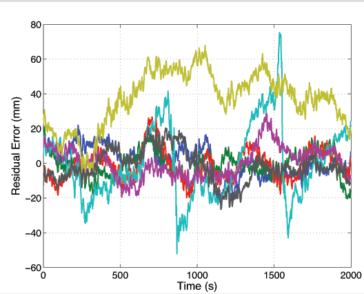
Phase Residual Analysis. Shown in Figures 3, 4, and 5 are 2,000-second segments of double-differenced phase residual time histories for data collected from a survey-grade, a low-quality patch, and a smartphone-grade antenna, respectively.
Figure 3. Survey-grade antenna. Each trace represents a residual for a different satellite pair. Ensemble average standard deviation 3.4 millimeters.Figure 4. Low-quality patch antenna. Ensemble average deviation 5.5 mm.Figure 5. Smartphone-grade antenna.Ensemble average deviation 11.4 mm.
To produce these residuals, the antenna position was locked to its estimated value within the CDGNSS filter. The residuals represent departures of the carrier phase measurements from perfect alignment at the average phase center of the antenna. Each different colored trace corresponds to a different satellite pair. While the data segments were not captured at the same time of day, they were captured at the same location, and thus the multipath environment was similar.
The ensemble average residual standard deviations increase with decreasing antenna quality. The residuals for the survey-grade, low-quality patch, and smartphone-grade antennas have ensemble average standard deviations of 3.4, 5.5 and 11.4 millimeters, respectively. This increase is due to the lower gain and less effective multipath suppression of the lower quality antennas.
Figure 5 shows the presence of outlier residuals in the data collected from the smartphone-grade antenna. These outliers, one of which persists for over 1,000 seconds, are likely caused by either large and irregular azimuth- and elevation-dependent antenna phase center variations or a combination of poor antenna gain in the direction of the non-reference satellite coupled with ample gain in the direction of a multipath signal such that the multipath signal is received with more power than the direct-path signal. Obvious outliers such as these can be automatically excluded by the CDGNSS filter via an innovations test. However, the standard deviation of the remaining residuals still remains large compared to that of the other antennas; the ensemble average standard deviation decreases from 11.4 to 8.6 millimeters upon exclusion of the two large outliers.
For antennas with a large ensemble average standard deviation in their double-differenced phase errors, the time correlation in the phase errors becomes more important. This time correlation, which persists for 100–200 seconds, is a well-studied phenomenon caused by slowly varying carrier phase multipath. While correlation is present in the residuals of all antenna types, and manifests approximately the same decorrelation time, its effect is more of a problem for low-quality antennas because the phase errors are larger. Such correlation, coupled with a large deviation, ultimately leads to a longer time to ambiguity resolution, shown later.
Given a smartphone antenna’s extremely poor gain and multipath suppression as compared to even a low-quality stand-alone patch antenna, one might question the wisdom of attempting a CDGNSS solution using such an antenna. However, the next section reveals that it is indeed possible to achieve a centimeter-accurate positioning solution using a smartphone GNSS antenna despite its poor properties.
CDGNSS with Smartphone Antenna
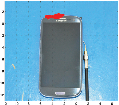
Figure 6 shows the result of an attempt to compute a CDGNSS solution using data collected from the GNSS antenna of a smartphone. The cluster of red near the top of the phone represents 400 CDGNSS position estimates over a 5-minute interval, superimposed on the photo and properly scaled. This cluster is referenced to a marker immediately under the phone whose position was surveyed to approximately 1-centimeter accuracy using a high-quality patch antenna. The mean of the cluster’s horizontal coordinates is approximately 2 centimeters from the phone’s internal GNSS antenna. Figure 6 shows the absolute horizontal accuracy of a CDGNSS solution through the smartphone’s antenna is approximately 2 centimeters.
Figure 6 . Successful CDGNSS solution using data collected from smartphone antenna. The red cluster represents 400 CDGNSS solutions over 5 minutes, superimposed and properly scaled.
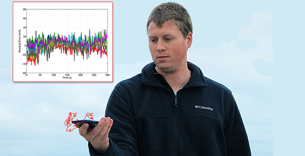
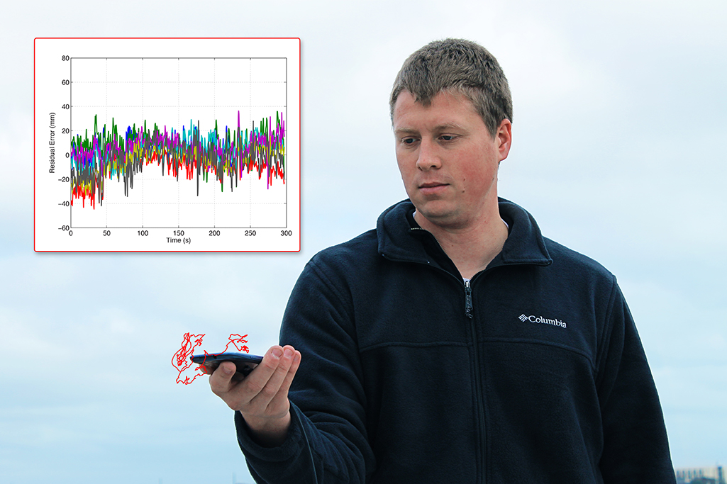
The data in Figure 6were collected with a large conductive backplane below the smartphone. However, the backplane is unnecessary. The opening photo shows the result of a CDGNSS positioning solution computed using data collected from the smartphone antenna while the device was held in the extended hand of the author. The cluster of red represents the computed 3-dimensional position of the phone over a 300-second interval, superimposed on the photo and properly scaled. The author’s hand moved slightly during the interval, as reflected in the figure.
The opening photo also shows the residuals corresponding to the handheld CDGNSS solution. This shows how the residuals look in practice for a scenario in which the phone is held by a user. The residuals look fairly clean, that is, they have a small variance and their mean is approximately zero. It is not uncommon for the residuals to look this good; however, cases do arise in which the residuals are considerably worse due to a combination of poor antenna gain in the direction of the non-reference satellite, coupled with ample gain in the direction of a multipath signal.
The possibility of CDGNSS-enabled centimeter positioning using a smartphone antenna has been previously conjectured, but — to our knowledge — Figure 6 and the opening photo represent the first published demonstrations that this is indeed possible. This significant result portends a vast expansion of centimeter-accurate positioning into the mass market. However, serious challenges must be overcome before mass-market CDGNSS can become practical. Some of these challenges will be studied in the next few sections.
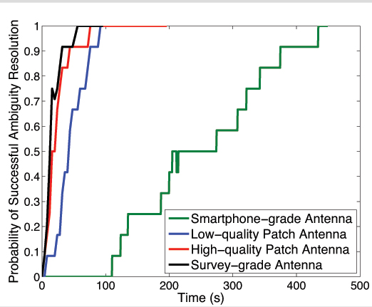
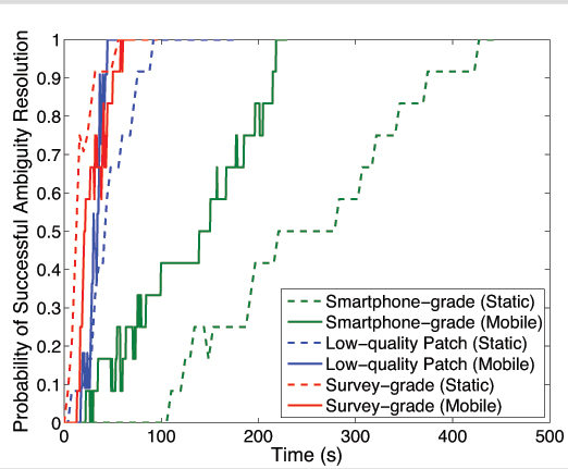
Static Scenario. Figure 7 shows the empirical probability of successful ambiguity resolution for data collected from four antennas, one of each of the different grades discussed earlier. For each antenna, seven satellites were tracked at approximately the same location and time of day. Each trace was computed from 12 batches of double-differenced carrier phase data.
Each trace represents an empirically-derived success rate computed from 12 batches of phase data as follows:
For a given batch, at each epoch the filter outputs its best estimate of the integer ambiguities on the basis of the data ingested thus far.
The estimate from step 1 is compared against the true set of integer ambiguities which were acquired in advance by processing a much longer batch of data. If correct, a flag is set at that epoch to “1”; if incorrect, the flag is set to 0.
For each epoch, the flags produced in step 2 are averaged across all 12 batches to generate each trace.
Figure 7. Residuals for CDGNSS solution depicted in the opening photo.
As shown by the green trace in Figure 7, the smartphone-grade antenna required 400 seconds to achieve a 90% ambiguity resolution success rate; in other words, it manifested a 400-second TAR at 90%. This would surely exceed the patience of most smartphone users. Also shown are traces for the other three antenna grades. The higher-quality antennas yield shorter TARs for a given success rate, primarily due to their superior multipath suppression.
Note that the loss in received signal power due to the smartphone antenna’s poor gain turns out to be tolerable — the signals arriving from the smartphone-grade antenna can be tracked without cycle slipping. Therefore, the outstanding challenge preventing fast ambiguity resolution for data collected from smartphone-grade antennas is the severe time-correlated multipath errors in the double-differenced carrier phase data.
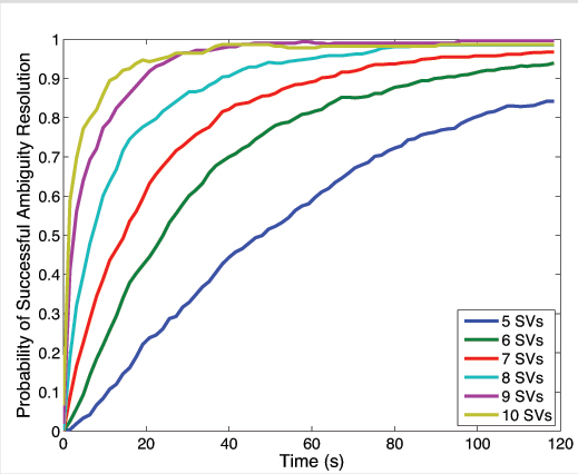
Decreasing TAR via More Signals. There are ways to mitigate the impact of multipath on the CDGNSS TAR, even the severe multipath experienced by low-quality antennas. It has been shown that the volume of the integer ambiguity search space, and thus TAR, decreases as a function of the number of double-differenced phase time histories available, which, for single-frequency CDGNSS, is one less than the number of satellites tracked. Consequently, an acceptable TAR can always be achieved with enough satellites tracked.
Figure 8 shows the reduction in TAR for an increasing number of satellites. Each trace was computed from 720 non-overlapping 2-minute batches of data taken from a survey-grade antenna over a 24-hour interval. A decreasing elevation mask angle was used to allow an increasing number of SVs to participate in the CDGNSS solution. For a given 2-minute batch of data, an elevation mask was first applied to all but the highest five satellites. Double-difference phase data from these satellites were then processed by the CDGNSS filter to compute an empirical probability of successful integer ambiguity resolution. Next, the elevation mask was reduced until one additional satellite was in view, and the process repeated to produce all traces shown.
Figure 8 makes clear that each additional double-differenced phase time history, although corrupted by its own multipath-induced phase errors, significantly decreases the overall TAR. Note that although Figure 8 was produced from data collected via a survey-grade antenna, a similar trend would apply for the smartphone-grade antenna. One implication of Figure 8 is that smartphone-based CDGNSS would benefit greatly from the additional double-differenced measurements that a multi-frequency GNSS receiver could provide. For example, at the time of writing there are 14 operational GPS satellites broadcasting unencrypted civil signals at the GPS L2 frequency (1227.6 MHz), and 7 broadcasting civil signals at the GPS L5 frequency (1176.45 MHz). With some modification of the smartphone GNSS antenna and chipset, these modernized GPS signals could be exploited to reduce TAR. However, the narrow profit margins on mass-market GNSS antennas and chipsets militate against multi-frequency architectures.
Figure 8. Probability of successful ambiguity resolution vs. time as a function of the number of satellite vehicles (SVs) tracked.
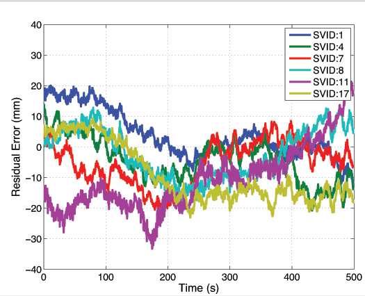
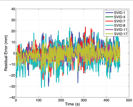
Decreasing TAR via Random Motion. There is a second way to reduce TAR under severe multipath conditions. Unlike TAR reduction via additional signals, the theory and practice of this second technique have not been previously treated in the literature. Moreover, the technique is well-suited for smartphones, which are typically hand-held and mobile. This simple technique consists of gently moving the smartphone in a quasi-random manner within a wavelength-scale volume. The key to this technique’s effectiveness is that, whereas multipath-induced phase measurement errors are typically time-correlated on the order of hundreds of seconds for a static receiving antenna, their spatial correlation is on the order of one wavelength, or approximately 19 centimeters at the GPS L1 frequency. As a result, random wavelength-scale antenna motion transforms the phase residuals from slowly-varying when the antenna is static, as shown in Figure 9, to quickly-varying when the antenna is dynamic, as shown in Figure 10.
Figure 9. Residuals for data captured from smartphone-grade antenna while static.Figure 10. Data from smartphone-grade antenna as it experienced wavelength-scale random motion, 2–5 cm/second.
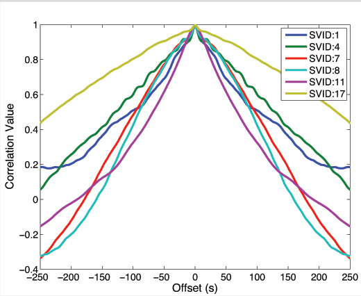
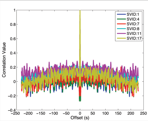
Put another way, autocorrelation time of the phase residuals decreases from hundreds of seconds when the antenna is static, as shown in Figure 11, to less than a second when the antenna is moved even slowly (a few centimeters per second), as shown in Figure 12. More vigorous antenna motion would be possible if the phone’s inertial devices were used to aid the phase tracking loops.
Figure 11. Autocorrelation functions corresponding to the phase residuals in Figure 9.Figure 12. Autocorrelation functions corresponding to phase residuals in Figure 10.
The shorter phase error decorrelation time resulting from random antenna motion effectively increases the information content per unit time that each double-differenced phase measurement provides to the CDGNSS filter, thus decreasing the time to ambiguity resolution.
Figure 13 compares empirical success rates for three different antennas under static and dynamic scenarios. As expected, motion reduces the time-to-ambiguity resolution for the smartphone-grade and low-quality patch antenna. But, somewhat counterintuitively, motion increases the TAR for the survey-grade antenna. This discrepancy reflects a tradeoff within the CDGNSS filter. While it is true that the phase measurement errors decorrelate much faster when the antenna is moving — increasing the per-epoch information provided to the filter — it is also the case that the filter can no longer employ a hard motion constraint. For the high-quality antennas, the increased information per epoch due to faster phase error decorrelation is completely counteracted by a loss in information per epoch due to uncertainty (lack of constraint) in the motion model. Also, for the high-quality antennas, multipath in the reference antenna’s phase measurements is not insignificant compared to multipath in the mobile antenna, and this reference multipath exhibits the usual 100–200 second correlation time for a static antenna. On the other hand, phase error decorrelation via random antenna motion offers the lower-quality antennas a larger net information gain because their multipath-induced phase errors are so large. Consequently, for the smartphone-grade antenna, motion substantially reduces the 90 percent success TAR, which drops from 400 to 215 seconds.
Figure 13. Probability of successful ambiguity resolution versus time for three different antennas under static and dynamic scenarios.
Conclusions and Future Work
Centimeter-accurate positioning was demonstrated based on data sampled from a smartphone-quality GNSS antenna. An empirical analysis revealed that the extremely poor multipath suppression of these antennas is the primary impediment to fast resolution of the integer ambiguities that arise in the carrier phase differential processing used to obtain centimeter accuracy. It was shown that, for low-quality smartphone-grade GNSS antennas, wavelength-scale random antenna motion substantially reduces the ambiguity resolution time.
Future work will study the effectiveness of combining antenna motion with a motion trajectory estimate derived from non-GNSS smartphone sensors to further reduce the integer ambiguity resolution time. This technique, which is a type of synthetic aperture processing applied to the double-differenced GNSS phase measurements, effectively points antenna gain enhancements in the direction of the overhead GNSS satellites, thereby suppressing multipath arriving from other directions. Preliminary results show that this technique offers modest benefit beyond the unaided random motion technique discussed herein.
Acknowledgment
The material in this article was first presented at ION GNSS+ 2014 in the paper “Centimeter Positioning with a Smartphone-Quality GNSS Antenna.”
Kenneth M. Pesyna, Jr. is a Ph.D. candidate in the Department of Electrical and Computer Engineering at the University of Texas at Austin. He is a member of the University of Texas Radionavigation Laboratory and the Wireless Networking and Communications Group.
Robert W. Heath, Jr. is a Cullen Trust Endowed Professor in Electrical and Computer Engineering at UT-Austin, and director of the Wireless Networking and Communications Group. He received his Ph.D. in electrical engineeringfrom Stanford.
Todd E. Humphreys is an assistant professor in the department of Aerospace Engineeringand Engineering Mechanics at UT-Austin, and director of the UT Radionavigation Laboratory. He received a Ph.D. in aerospace engineering from Cornell University.
A decade’s progress: on the left, the 2004 AXTracker. On the right, the 2014 GTO.
Over a decade ago GPS World covered the introduction of the first battery-powered asset tracking device that operated over satellite networks, the AXTracker (“Going the Distance,” October 2003). More than ten years later, the technology has proven the market, and opened new markets. Battery powered tracking devices today are used for the expected, like enterprise asset tracking for trailers, containers, and field equipment, to the unexpected like tracking sea currents, ranging sheep, and weather balloons.
The newest products are dramatically smaller, have much longer battery life, and pack accelerometers and Bluetooth for mobile phone connectivity and wireless sensor interface. Yet power management, cellular and satellite communications, and environmental ruggedness remain the technical challenge.
Battery Technology. Advances have occurred in rechargeable technologies, largely driven by cellular telephones, military and automotive, but advances in primary batteries for industrial use are limited. Environmental operation is the problem. It remains extremely difficult to produce a primary cell that retains power for a decade while exposed to industrial temperature extremes. Global GPS tags for industrial use must operate in industrial temperature ranges of -40 C to + 85 C (-40 to + 185 F) while limiting self-discharge to enable operation over many years. Primary cells providing utility over the industrial temperature range with low self-discharge rates remain the same as available ten years ago.LiMnO2 (lithium/manganese dioxide) and Li-SOCl2 (lithium-thionyl chloride) are still the leading chemistries.
Lessons learned from field deployments have produced quality improvements and better field longevity and yield. Not all AA batteries with the same paper specifications survive equally, so developers must be wary. Through power reductions in satellite communications and GPS technology discussed below, the asset tag of today can enjoy a volumetric and cost reduction for batteries while achieving the same service duration.
GSatellite Network Technology
Ten years ago, the available global commercial satellite machine-to-machine (data) networks included Iridium, Orbcomm, INMARSAT and Globalstar. Though several of the satellite network service providers are replacing retired satellites, the technology remains unchanged and developers are left with the same choices today as ten years ago. Each satellite network offers different strengths and weaknesses for specific M2M field applications with different power budgets required. The AXTracker of a decade ago utilized the Globasltar simplex capability specifically because of the power budget profile for data delivery. From a satellite network power perspective, the limitations of one-way (field to cloud) satellite solutions employed by that first tracker continue to out-weigh other satellite network offerings.
In order to utilize the available satellite networks, the asset tag must integrate satellite communication circuitry. In a world of continuous technology improvements, the satellite transceiver evolution has been slow. Over the past decade most of the major satellite network providers have next-generation transceivers. However, the new technology has only marginally improved the power issues for battery-powered industrial GPS tags. For example, Iridium’s first OEM transceiver, the 9601, required peak power of 7.5W, with average power of 1.8W. Their latest transceiver, the 9603, is much smaller physically but still requires the same 7.5W peak, though average power is now 1W. Average power for an Iridium data packet delivery is the measure of the power used over message transmit and receive as well as idle times while accessing the satellite network. This average power for Iridium is the parameter used for calculating message delivery per a given battery capacity but peak power must also be supplied in any design that seeks to use the data service. Orbcomm and INMARSAT technology have similar power budgets due to their communications handshake requirements to access the network. For these systems, it remains difficult to source this power capacity and peak current requirements at -40C environmental temperature using batteries only.
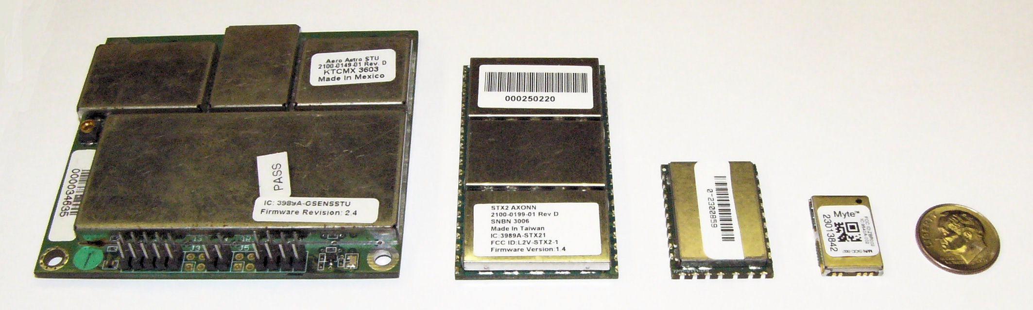
(From left) STX1, STX2. STX3, MYTE.
Similar power improvements are available in the Globalstar simplex system. The Globalstar system is different than the other commercial M2M satellite networks in that data is merely transmitted one-way from the GPS tag to the network, thus removing the power needs for handshaking with the network to deliver data. The STX1 radio transmitter of eleven years ago required a whopping 6W during transmit, but thankfully was soon replaced with the STX2 radio transmitter. The STX2 is still the primary simplex transmitter in use today and requires 1.65W during the one-way short-packet bursts. The much lower and short duration requirements for power were, and are, the deciding factor for network selection for the original battery operated GPS tag. Today, the Geoforce MYTE radio transmitter embedded in the GT1 and GT0 devices requires 1.1W peak, an 82% reduction from the short-lived STX1 and a 33% reduction from the STX2. For simplex service, the peak power is used to calculate message delivery per available battery capacity since there are no network access or receive power requirements. Ten years of simplex transmitter evolution and size reduction enable fundamentally smaller asset tags while providing a 30% to 40% reduction in power required for satellite data delivery.
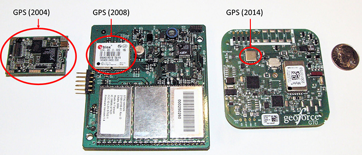
GPS Technology. Improvements here have made the greatest power budget impact for tag developers, greatly reducing the total power and current required to ascertain a location. GPS chipsets of ten years ago would kill today’s smartphones in hours. The newest GPS cores operate at much lower voltages and operating currents.The GPS engine of the first AXTracker operated at 3.3V and required 70 mA operating current for an average cold-fix time of 45 seconds (10.4 Wsec of battery power). Geoforce’s GT1 and GT0 embed the Origin Spider GPS module that incorporates the SiRFstarIV GPS chipset. This GPS engine operates at 1.8V with 37 mA operating current and an average cold-fix time of 35 seconds (2.3 Wsec). Even for challenging GPS field deployments, this represents a conservative 75 percent power reduction for location determination.
The power budget rule of thumb ten years ago was 20 percent went into idle sleep current, with the remaining 80 percent split roughly equally between satellite communications and GPS location determination. Improvements in satellite transmitter and GPS power technology have shifted the power budget ratio to 40 percent satellite communications and roughly equal power between idle sleep current and GPS location determination, for a net overall power reduction of roughly 33 percent.This means that the tag of today can last 50 percent longer than the tracker a decade ago with the same battery capacity. Alternatively, today’s tracker can have 33 to 50 percent fewer batteries to achieve the same service life depending on operational configuration.
GPS chipset evolution: from 2004 (left) to 2008 (center) to 2014 (right).
What about Cellular? Ten years ago cellular M2M systems were as much in their infancy as satellite systems. The advance of cellular telemetry tracking systems has exploded far faster than satellite systems for powered fleet-type assets, yet there are far fewer battery-powered cellular systems than satellite today. Two primary contributing technology factors impede the introduction of battery-powered cellular systems: network availability and network power requirements. Cellular tracking services have good availability as long as the asset operating area greatly overlaps consumer cellphone service.International and industrial applications have lower cellular regional overlap. As a result, battery powered cellular asset tracking devices remains a niche market.
Even if network coverage is acceptable, power budget asserts real technical problems for the developer.Cellular transceivers have similar power requirements as two-way satellite network, with high peak currents and relatively long network access dwell times. A multi-year, industrial temperature GPS asset tag operating over cellular is similar to a two-way satellite, requiring large capacity primary batteries, or rechargeable configurations that require frequent access to line power.For this reason, these battery-powered cellular asset tag technologies are seeing slower market insertion, leaving unpowered, industrial and international asset management applications to simplex satellite solutions.
Environmental Packaging
The largest product evolution observed in battery-powered asset tag technology is industrial packaging. Electronic and battery technology has remained fundamentally unchanged, however the packaging of these devices has changed significantly. Over the past ten years, the GPS asset tag has transitioned through many design and package iterations, all seeking to improve the reliability and service life of the industrial tag. Conflicting use-case requirements have contributed to field failures. Customers often demand features similar to commercial electronics systems such as rechargeable or replaceable batteries, or connectivity of remote sensors. While these features are highly desirable, they also lead to field failures in rugged, industrial environments. Chief among environmental failures is water intrusion.
Customer expectations for wired sensor connectivity or battery replacement require connectors for wiring or panels to access the battery compartment with gaskets to prevent water intrusion. The stressors of industrial, multi-year fielded devices are unlike consumer electronics systems. Industrial tags are subjected to directed pressure washing, often at forces sufficient to cut plastic. And unlike commercial electronic systems, the industrial tags see the full temperature range of automotive-grade electronics while still providing compartments for battery replacement (something that most automotive electronics products do not require). Beyond liquid water intrusion, many products succumb to water vapor intrusion that subsequently condenses inside the device due to large temperature swings. Gaskets designed to prevent water are less able to prevent passage of small amounts of atmospheric vapor due to a vacuum created on temperature drop. The effect is easy to visualize if we apply the ideal gas law, PV = nRT where P is pressure, V is volume and T is temperature (n and R are constants). For a given volume inside the tag, the pressure changes proportionally with temperature, thus a tag that experiences a drop in temperature will also experience a drop in relative pressure and will pull in minute amounts of water vapor, which over time will condense and cause product failure.
Several obvious solutions exist, starting with removal of internal air volume through encapsulation (potting). Encapsulation seeks to take V to zero, thus making the device impervious to vapor intrusion caused by temperature swings. Additionally gaskets can be removed at the tradeoff of inaccessible batteries.
Putting It All Together
The Geoforce GT0 leverages over a decade of lessons learned. It incorporates the smallest, lowest power simplex transmitter, salvaging 33% of power required for satellite communications. It also uses the Origin Spider GPS module, which includes the latest SiRFstarIV GPS chipsets, harvesting 50% of the power for location fixes. The GT0 also incorporates the latest circular polarized antenna technology from Tallysman, with unparalleled performance compared to previously available commercial patch antennas.
The combined antenna design and power savings enable the GT0 to require only half of the batteries with an 85% reduction of device volume to achieve the same or better field service life compared with the tracker of ten years ago. The lower volume alone reduces the risk for water intrusion, but the risk is further reduced by the use of encapsulation and non-replaceable batteries. The GT0 is therefore fully sealed, disposable and encapsulated. This packaging concept makes the GT0 extremely rugged and impervious to directed water or water vapor intrusion. Thus, the GT0 is truly in a class of its own. The technology advancements and lessons learned over the past decade have enabled mechanical footprint and volumetric reduction of the global, battery-powered GPS asset tag.
The GT0 combines the smallest, lowest power satellite and GPS engines with innovative packaging to create the smallest, industrial-grade global satellite asset management tag available anywhere, setting the bar for size, value and performance.
Asset managers today need more than dots on a map. They need asset utilization metrics that provide actionable information for improving operations. Knowing where an asset is and where it is moving is sometimes enough, and for these applications GPS enabled, battery-powered tags provide supreme value.New tags provide the value of track and trace, but also can relay data from nearby sensors using short-range Bluetooth wireless interfaces.This capability will evolve the utility of yesterday’s global tag, closing the gap from location only toward satellite-based telematics, but that is a story for another day.
Gary Naden serves as Chief Technology Officer at Geoforce, manufacturer of satellite telemetry asset tags for oilfield and hazardous environment use.
UBL Interactive, Inc. today announced a global data syndication agreement with Amsterdam-based NavAds to help businesses ensure their profiles appear in navigation services and devices.
The NavAds agreement will improve the quality of the business listing information and the breadth of distribution for UBL customers. NavAds specializes in business listing insertion and advertising on navigation services such as TomTom, Garmin, Nokia HERE, Waze, Yandex, and others.
UBL CEO, Doyal Bryant, said the partnership was significant not only because it addressed the growing use of mapping tools, but because it was a global arrangement. “UBL is focused on an increasingly mobile world, and services which are not confined by national borders. Navigation services are constantly changing and evolving and with our NavAds partnership, our customers can be assured anywhere globally, they will get the benefit of the most advanced distribution in the mapping space,” he said. “It extends our place as the global leader in business listing syndication, with more publishers and international local partnerships than any others in the space.”
NavAds CEO, Lex ten Veen, said UBL would bring many new owner-verified business locations to the NavAds platform and network. “Businesses need to be found on these navigation devices, and NavAds can give UBL’s customers great confidence their visibility is fully optimized,” he said.
The services will be integrated into UBL product sets immediately.
Two new products have found ways to turn smartphones into personal protection devices. One of the two products includes a wearable monitor.
Photo: First Sign Technologies
Mace Wear Pod
The Mace Wear Pod uses a wearable device in conjunction with a smartphone app. First Sign Technologies, in partnership with Mace Wear, has launched the Mace Wear Pod, which acts as a personal security system against violent crimes. At the first sign of a violent attack, an assault alarm is activated and the speaker lets the attacker know that evidence has been collected and help is on the way. The device automatically begins to collect evidence, take photos, and call for help, which will help identify, apprehend, prosecute and deter attackers, the makers say.
The Mace Wear Pod can be worn in five ways as a headband, wristband, key chain, belt clip and pendant. For those not wearing the pod, the mobile app, which can be downloaded on iPhone and Android, can also be activated in three ways, by hitting the alert button, by shaking your phone, or by setting a time to check-in — the alarm is activated if the check in doesn’t take place.
First Sign Technologies was launched in January 2014. Following a successful crowd-funding campaign, the product is now available with one year of monitoring service for $120.
“There is a demand for personal protection and with the advances in wearable technology, we want to create products that give peace of mind,” said First Sign President Rachel Emanuele. “Mace is an ideal partner to help us expand our product line and help promote safety to all who seek it.”
The products are expected to be available in more than 1,000 stores such as Dick’s Sporting Goods, Sports Authority and Sears. Demonstration videos are posted here.
Photo: STOP-ATTACK
STOP-ATTACK
Another new app launching this month, STOP-ATTACK, uses smartphone technology to send alerts in case of bullying or harassment. STOP-ATTACK, available on both Android and Apple platforms, records audio and video evidence and alerts contacts of trouble in a matter of seconds, sending GPS coordinates to a designated Panic List and first responders.
“We need to stop the senseless violence and assaults in this world,” said Anthony “Tony” Bright, the creator of STOP-ATTACK. “Our hope is that STOP-ATTACK.com will be a powerful tool in this struggle. The app has been developed with simplicity as a core feature, so that even younger children can be protected, giving parents much-needed peace of mind.” The CEO will be presenting the STOP-ATTACK app at the Pre-Grammy Awards VIP Gift Lounge and The Oscars Gift Lounge hosted by GBK productions this February.
The app can be downloaded in the Google Play or iTunes store, and is available for free now until Feb. 8, 2015.
STOP-ATTACK users will be able to customize many aspects of the app, such as creating a “Panic List” of people for the app to contact in an emergency, from friends and family to local first responders. When a user activates STOP-ATTACK, the app instantly begins recording live audio and video and uploading the stream to the cloud. Panic List contacts and designated first responders are notified immediately or after a brief, user-determined delay. The app will send the contacts a link with the GPS location and the recording of the incident.
A hot key allows for quick and discrete activation of the STOP-ATTACK app. For instance, a bully need not know they’re being recorded until presented with the evidence by a school authority. On the other hand, it’s sometimes advantageous to let everyone know that STOP-ATTACK is recording; users can choose for the app to play an alarm sound and turn on the camera light when activated, a strong deterrent to a would-be attacker.
The developers of STOP-ATTACK have created a pair of explainer videos to showcase exactly how the app works in typical usage scenarios: “Always Be Prepared,” “Bullying.”
Navman Wireless is launching an integrated vehicle tracking and camera technology product aimed at helping businesses manage risk, improve road safety, and reduce insurance costs. The product, labeled “360 Degree,” integrates telematics, vehicle tracking technology and in-cab safety camera equipment to create what Navman calls a “seamless umbrella of preventive and protective technology.”
The system is designed to help mitigate poor driving, reducing on-the-road risk. “Prevention is better than cure, and using data from telematics and vehicle tracking software to help mitigate poor driving significantly reduces on-road risk, but when you are on the road you need 360 degrees of protection,” said Hutchins.
Navman Wireless describes the in-cab safety camera equipment, supplied by Smart Witness, as a safety net. “It’s a last line of defense for drivers and fleet businesses in those unfortunate circumstances beyond their control,”said Scott Hutchins, VP sales UK and Ireland, Navman Wireless. “The introduction of in-cab camera technology not only protects the driver and business from not-at-fault claims, but also enables us to offer a complete proactive and preventative solution that has the potential to deliver measurable improvements in terms of accident and cost reduction.”
“It’s about prevention and protection. Telematics technology is integral to a successful preventive safety strategy because it can be effectively utilized to assess drivers and ensure safety and quality,” Hutchins said.
LoJack is introducing at NADA 2015 its Fleet Management Lite offering, a new version of the service designed to be an affordable, turnkey SaaS (software as a service-based) telematics solution. Fleet Management Lite will enable business owners with small- to medium-sized fleets to realize the benefits of an advanced fleet telematics system, LoJack said. The can be quickly deployed, making it a good choice for loaner vehicle fleets in many of today’s dealerships, the company said.
Another location-based program is LoJack Pre-Install, which enables automotive dealerships to pre-load vehicles in their inventory with the LoJack Stolen Vehicle Recovery System before the vehicle is sold to the customer.
“Our commitment to LoJack’s dealership network is at the center of who we are as a brand and a company,” said Randy Ortiz, president and CEO of LoJack Corporation. “Through a combination of strategic partnerships and corporate research and development, we’re fully invested in our mission to deliver sophisticated and reliable connected car and telematics solutions to the dealership community. Our goal is that each of these solutions enables dealerships across the country to increase revenue and improve operational efficiencies while effectively serving customers.”
The Janam XM5 series has both Windows and Android OS.
Janam Technologies LLC, a provider of rugged mobile computers that scan barcodes and communicate wirelessly, today announced the launch of its XM5 family of rugged mobile computers. Designed to maximize the mobility investments of enterprise and government organizations, the new XM5 has high-sensitivity GPS and Assisted GPS, and supports Windows Embedded Handheld 6.5 and Android operating systems on the same hardware.
Having both OS enables customers to choose the OS strategy and application migration schedule that best meet their mobility requirements, Janam said.
The XM5 provides the power and flexibility required by mobile workers in field sales, field service, public safety, direct store delivery and transportation and logistics markets, Janam said. Customers can choose between integrated, best-in-class, 1D/2D imager or 1D laser scanner for instant decoding of the hardest-to-read barcodes. Embedded RFID and NFC reading capabilities ensure more efficiency and accuracy in a variety of applications including inventory management, asset tracking, personal identification and mobile point of sale.
“Janam’s XM5 is one of the few rugged mobile computers that allows a customer to migrate from Windows to Android without purchasing new hardware,” said Harry B. Lerner, CEO of Janam. “Packed with all the features that enterprise requires, built to exacting standards of quality and available at an attractive price point, the XM5 catapults Janam to the lead position among hardware providers that not only listen to what customers need, but deliver to those requirements.”
The XM5 comes with either a QWERTY or Numeric keypad and a specially-fortified 3.5-inch VGA display that withstands heavy-duty use. It also offers 802.11a/b/g/n dual-band WLAN and 4G-ready UMTS/HSPA+/HSDPA/HSUPA/GSM WWAN communications for access to high-quality and reliable voice and data inside and outside the four walls.
Built to withstand the rigors of everyday use in the enterprise, the XM5 is sealed to IP65 standards, can withstand five foot drops to concrete and is UL-certified for hazardous environments. In addition, the XM5 ships with a 4000mAh rechargeable Li-ion battery, providing extended battery life as a standard feature, not an optional one.
XM5 Features
Android 4.2 and Microsoft Windows Embedded Handheld 6.5 operating systems
This year’s CES featured the usual big TV screens, loudspeakers, wearables, 3D printers, drones and connected vehicles surrounded by 150,000 attendees over several Las Vegas meeting venues. What was interesting was the continued rise of autonomous, or self-driving, vehicles and platforms. Lost in all of the noise was a small, but important, location-based services enclave that consisted of GPS-enabled wearables and indoor positioning.
LAS VEGAS—A big chunk of the estimated 30 billion worldwide connected devices will be those linked to vehicles, say industry experts at the International Consumer Electronics Show here. Nearly all automakers had a presence at CES — all with a long-term connected vehicle strategy.
No matter how big and exhausting CES is, with long taxi lines and 150,000 attendees, there is good reason to come a day before the giant conference, as the Consumer Telematics Show and AT&T Developer’s Conference feature many industry executives and new developments. At the Consumer Telematics Show, speakers explained how and why connected vehicles are transitioning to autonomous capability.
The connected car industry has matured to the point where technology and market points are coming together, said Thilo Koslowski, Gartner vice president and practice leader, automotive vehicle ICT mobility, at CTS. “The opportunity of connected vehicles are becoming the center of mobile and [Internet of Things] innovations. It has come from, in 1997, a pure telematics safety and security device to vehicle integration, digital lifestyle convergence and Internet of cars,” he said. “At the end of the year, there will be 25 million connected vehicles in the world, but most in mature markets. That might not look like a lot, but only in five more years, I think that number is going to 150 million vehicles.”
In some cases, the newer outfitted vehicles will have only safety and security features, Koslowski said, but most will have two-way data communication, part of the 30 billion devices connected by 2020. He predicted last year that most automakers would have shifted general mobile applications to vehicle and customer-specific services.
Koslowski says the top connected car features that consumers have asked for include automated map updates, real-time weather and news, parking spot finder and driving assessment and coaching. “Consumers don’t want application downloads directly into the car. In addition, in-vehicle media purchases are not there yet, as are in-vehicle social networking updates,” he said. “I predicted in 2013 that 25 percent of the automakers would monetize mobile commerce transactions in their connected vehicle offerings such as parking, buying gas, etc.,” he said.
Self-Aware Vehicle Emergence
Imagine sleeping, or reading, in your car during the morning commute. It may be a reality, but major technical, cultural and legal issues need to be resolved before fully autonomous vehicles hit the road. “There is going to be trouble if [automakers] don’t get consumers involved early on. Or allow governments and insurance companies telling people when to hit the button (to drive),” Koslowski said. “You press the [drive yourself] button and you pay 30 percent more in insurance. About 39 percent of those we surveyed are interested in some sort of self-driving car — that doesn’t mean fully autonomous vehicles. But 61 percent say they are not ready.”
Koslowski says there is a lot of education that includes basic acceptance of the technology and trust that it really works. “There usually is a 30-second rule. The first 30 seconds is ‘holy moly, this thing drives itself’,” he said. “The second 30 seconds is ‘is this beneficial?’ There are real benefits such as reducing the cost of accidents, which amount to $900 per U.S. citizen.”
In terms of cyber security and privacy, Koslowski said it’s a big deal for autonomous vehicles. “A couple of breaches will be a big deal. Still, consumers are not that paranoid. They are willing to share information, especially if there is a monetary or societal function,” he said.
Cost is still big factor that will drive the adoption of autonomous vehicles. Koslowski says that consumers polled will only pay an additional $1,404 for autonomous capability. The cost of a test vehicle, right now, is about $85,000. “The good news is that number is coming down. It is shrinking to less than $6,595,” he said.
At the Transportation Research Board meeting a week after CES in Washington, Chris Urmson, who heads Google’s self-driving vehicle program, said the Kentucky Fried Chicken bucket-looking gizmo on top of their car cost $70,000 alone.
Cost aside, by 2016, three automakers will have concrete plans for upcoming autonomous vehicle launches, Koslowski said. “This is happening a lot faster from a technology standpoint than experts thought it would,” he said.
Overall, Koslowski said that big IT companies need to step up to make autonomous vehicles work. “Governments are a little behind. The slowness of automotive companies also make them vulnerable to technology companies to step in and take over the industry,” he said.
Indoor Positioning and Other Location Markets at CES
Such companies as CSR were at CES and said the show was good for indoor location providers. “CES was good for us. We had good interest in our live demo of indoor location where customers were free to walk around testing the performance of our (solution). We also saw a lot of interest from the automotive market for an indoor/outdoor navigation (product), such as being able to find your way back to the car in a complex shopping mall and the best place to park for access to your indoor destination,” said Dave Huntingford, CSR’s director of product line for location.
In 2015, the company believes that one of the key drivers for indoor location will be the ubiquity of maps for public locations, Huntingford said. “The availability of indoor maps for malls, airports and retail chains will help drive indoor location awareness with consumers for both utility value (not getting lost) and retail marketing applications,” he said. “We also expect to see a variety of social networking applications supporting indoor location, reflecting the fact that we spend the vast majority of time indoors.”
Huntingford believes a key limitation of many indoor technologies is the requirement to have dedicated, or upgraded, infrastructure such as BT Smart beacons or updated Wi-Fi access points with new location capabilities, and a dedicated manual survey of the building to measure indoor Wi-Fi signatures.
At CES, Magellan rolled out its line of 5-inch RoadMate Auto GPS Devices with 3D buildings and landmarks. “The units retail from $169 to $229. “We are surprised at the interest our PNDs are having in the market, particularly with back-up video,” said William Strand, Magellan associate director, product marketing. “The dash camera is a small market, but catching on to block insurance fraud.”
In other CES news:
Audi pulled off a coup when it invited journalists to drive with its autonomous vehicle from San Francisco to Las Vegas.
Most location companies have wearables product lines that are making retail chains take notice.
Transportation Research Board Meeting Becoming Big Autonomous Show
WASHINGTON—The Transportation Research Board Annual Meeting here has grown to be one of the bigger autonomous vehicle meetings, with 12,000 mainly government execs and academics meeting.
About 300 people showed up for a panel headlined by Chris Urmson, who heads up Google’s autonomous vehicle program. All was well and good hearing about Google’s self-driving vehicle technology except TRB had 100 chairs for 300 attendees…a lot of people left. But that is the level of interest autonomous vehicle is having in the government and academic community.
“We are planning to find out how our car does with red lights flashing in front of it. The software will figure out, along with GPS and insertional and high-resolution maps,” Urmson said. “The world isn’t empty. Our vehicle has to know about the pick-up making a lane change, the bicyclist pedaling next to it.”
Urmson said there are no sensors on the market that power the car — Google makes them in-house.
In other TRB news, TomTom announced it is partnering with the I-95 Corridor Coalition. The company is using one of three main real-time traffic products in its portfolio, said Nick Cohn, TomTom senior business developer. “It is all about our TomTom Traffic Flow product, which provides speed information for individual road segments every minute, based on our mix of probe data sources,” he said. “This is one of three main real-time traffic products we have. TomTom Traffic provides one-minute updates of locations and delays of traffic jams and other traffic incidents. The third product is a set of APIs for providing, for example, travel times that can be displayed on variable message signs along roadways to inform drivers about delays.”
The government market is a steady business for TomTom, which has seen traffic management success mainly in European cities such as Berlin, Rome and London, Cohn said.
Start of the 550 mile piloted drive from Silicon Valley to Las Vegas: Ricky Hudi, Executive Vice President Electric/Electronic Development, (left) and Ewald Gössmann, Excecutive Director Electronic Research Lab California (ERL), (third from right) drop the flag for the Audi A7 piloted driving concept car. Photo: Audi
In the wake of CES and the North American International Auto Show in Detroit, it’s clear that times are a-changing. Self-driving concept cars filled three football-field-sized areas to show off what lies ahead. Verizon and Ford did a cosmic switcheroo, with Verizon morphing into the auto space and Ford starting a transformation into a mobility company. Automated reality/augmented reality isn’t as big as would be expected, and is suffering from a lack of content. Wearables continue to do remarkable things, notably in the health and fitness sector, and smart watches will become more exciting with interaction to vehicles and home.
Janice Partyka
When Mark Field, current CEO of Ford, announced the Ford Sync from the CES stage in 2007, attendees found the presence of an auto company at CES to be out of place. The auto industry was considered Neanderthals of tech. Today, the most exciting mobile technology is vehicle related, and more exciting developments from the auto industry were seen in Las Vegas, rather than Detroit.
Field was back at CES with a visionary perspective that Ford isn’t going to be just about cars and trucks. He is broadening Ford’s focus to mobility in preparation of the changes in transportation that will occur in response to global megatrends of urbanization, growth of the middle class, air-quality issues and evolving consumer attitudes. To test out new ideas of flexible user-ship and collaborative transportation, Ford is operating 25 experiments around the world to test out solutions for specific mobility challenges. Ford is looking to be a leader and enabler of a market where people may be sharing or swapping vehicles or relying on crowd-based transportation. It is refreshing to see out-of-the-box thinking from Detroit.
Ford Mobility Experiment in London — driving-on-demand with Ford fleet. Photo: Ford
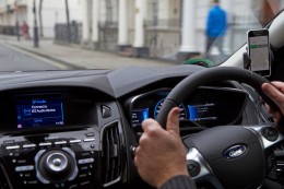
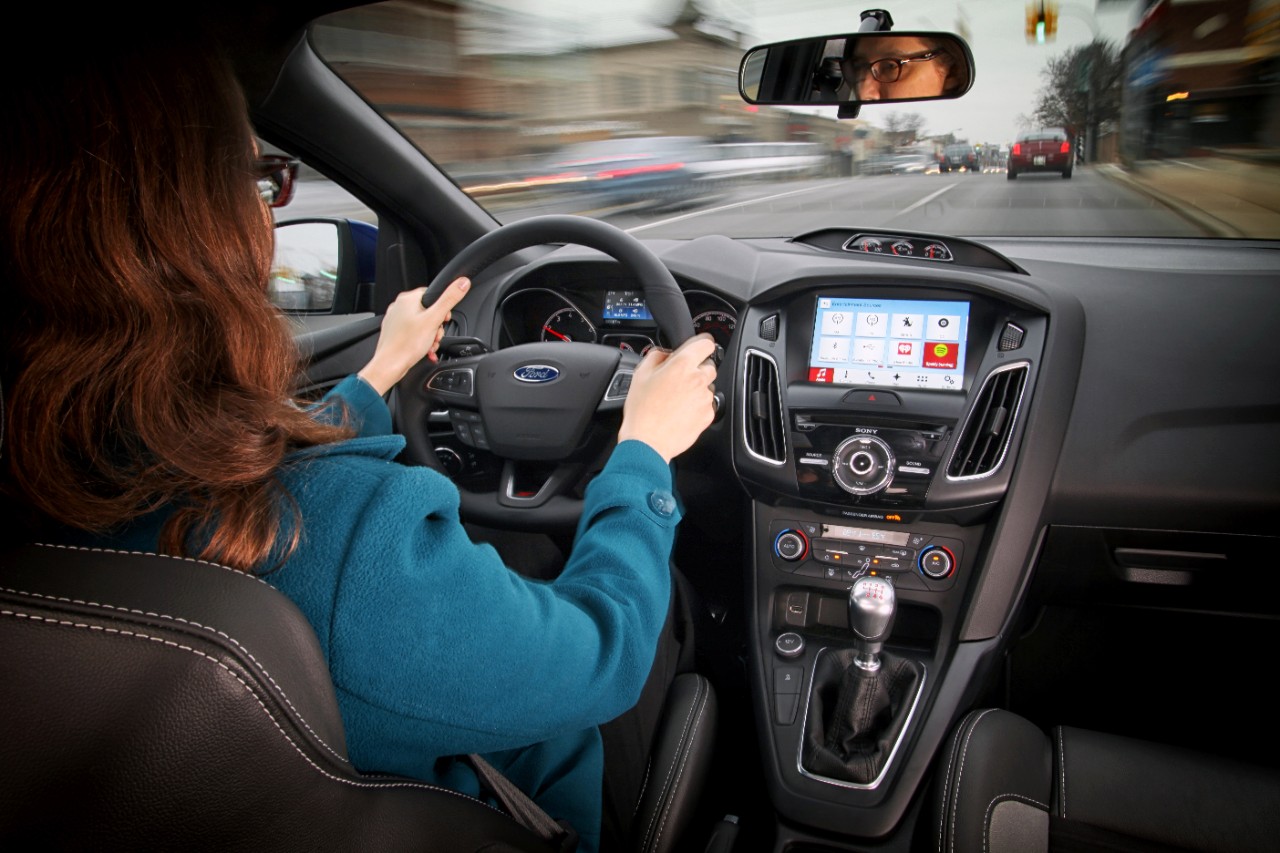
Far from its beginnings in 2007, Ford announced SYNC 3, an updated version of its in-vehicle communication and information system. SYNC technology is already in 10 million vehicles on the road. SYNC 3 will be released in new car models this year and will include more conversational speech recognition, a more smartphone-like experience with a touch screen and easier-to-read graphics. In addition, AppLink 3.0 will roll out and give drivers the ability to access their navigation app — much as they do on a smartphone — on in-vehicle touch screens.
SYNC 3 has been designed to keep the drivers eyes on the road and hands on the wheel, even when controlling their favorite phone apps. Photo: Ford
You may recall that GM had announced OnStar would be dropping Verizon for AT&T communications staring in 2015. The announcement of Verizon Vehicle, a new connected vehicle service that duplicates some of the features of OnStar, must be the impetus. The subscription-based service will be compatible with all vehicle models sold in the U.S. since 1996. The service will include GPS-directed roadside assistance, crash notification, emergency assistance with a live agent, a hotline to connect with mechanics on vehicle issues, maintenance alerts, and stolen vehicle location assistance. Notably, the offering doesn’t include navigation, a mainstay of OnStar, but readily available on smartphones. The service uses an OBD II dongle and a head unit that can attach to a visor and contains a Bluetooth speaker and call buttons.
Mercedes-Benz, Audi and BMW all showed advances in self-driving vehicles. Mercedes-Benz demoed the F015 Luxury in Motion concept car, which is fully autonomous and completely powered by a battery and fuel cell. Audi impressed by having its own concept vehicle drive itself from Palo Alto, California, to Las Vegas. BMW offered demonstrations of its i3 electric car, with ActiveAssist technology, able to prevent collisions at speeds up to 15 mph.
Delphi and Valeo technology suggest that current adaptive cruise-control systems may soon add self-steering. Drivers could allow the car to take over in stop-and-go traffic and on long highway segments. Although unlikely to see production in the short term, Delphi showed the full capabilities of its self-driving technology in an urban environment.
The next big feature to be commercialized during our wait for automated driving is self-parking. As demonstrated by BMW, the driver arrives at a parking garage entrance, gets out of the car, and sends it to find a parking place. When ready to depart, the driver summons the car, which drives itself to a special pickup zone in front of a parking garage. BMW says it will be offering self-parking cars in one to two years.
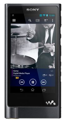
The Sony Walkman, now $1,100. Photo: Sony
Unfortunately, augmented reality hasn’t quite lived up to the hype, but Hyundai is showcasing a production-ready augmented reality heads-up display concept. It’s an easy-to-understand system with animated information and warnings to describe road conditions ahead. For instance, it provides warnings when another car is about to unexpectedly enter the car’s lane, and shows arrows leading to exit ramps, highlighted street signs and one-way street markings. Hyundai has linked the augmented heads-up display to a wearable band that will vibrate with warnings. The band includes a heart-rate monitor that can notify 911 if a driver’s heart rate changes rapidly.
I don’t want to neglect the things in life that don’t change. It is comforting to know that Palm Pilots, record players and Walkmans are back at CES. The new Sony Walkman will set you back $1,100. So things do change.
 Mojio, an open platform for connecting cars, has announced a partnership with Dooing, a new team management platform for businesses that can dispatch jobs and track teams.