The May issue of GPS World carries these three expert opinions on the question: How are autonomous vehicles and V2V technologies driving innovation within the GNSS industry?
Chaminda Basnyake
Chaminda Basnyake
Principal Engineer, Market Development,
Locata Corporation
We still have technical and cost versus performance challenges to meet the PNT needs of V2V and AV. Positioning and even timing expectations in deep urban areas are still not met reliably. As a result, ad hoc methods such as HD map-based nav — methods that work but are not scalable — have emerged. Innovations to deal with multipath, signal visibility and geometry are critical. Solutions that enable real-time mapping will be essential for scalable AV deployment.
Curtis Hay
Curtis Hay
Technical Fellow, GPS & Maps,
General Motors
Four key areas the commercial GNSS industry is pursuing include: low-cost, high-volume dual-frequency chipsets; broadly available PPP and network RTK corrections delivered either through mobile IP or satellite; precise maps for highways, urban centers and trunk roads that achieve 10-cm localization relative to WGS-84; and improved integrity monitoring and fault detection. The National Highway Transportation and Safety Administration also released a proposed rule-making with tight standards for GNSS performance: 1.5 meters, 1-sigma confidence.
Jonathan Auld
Jonathan Auld
Director, Safety Critical Systems,
NovAtel
Unlike traditional GNSS applications, automotive positioning requires high-precision accuracy at extremely low cost and size. Most importantly, this performance must be achieved with high reliability while operating in the toughest environments. Solving this positioning challenge is driving innovation in the system engineering of multi-frequency receivers and antennas along with extending performance through sensor fusion with lower cost devices. Additionally, there is significant work in the area of safety and integrity for land-based applications.
Here’s a preview of the V2V countdown article from the May issue, introduced by Chaminda Basnyake, an engineer at Locata Corporation:
The U.S. Department of Transportation (USDOT) released a Notice of Proposed Rulemaking (NPRM) in December 2016 for the deployment of Dedicated Short Range Communications (DSRC)-based vehicle-to-vehicle (V2V) safety applications as part of the connected vehicles (CV) and automated vehicles (AV) initiative. If all goes well, this mean a V2V deployment mandate for new passenger vehicles likely starting in 2021 and reaching all new vehicles within 2–3 years.
Standards required for V2V deployment were published in 2016 or before, including the V2V Minimum Performance Requirements SAE 2945/1, leading the way for commercial product development. The USDOT, which has been the catalyst behind V2V industry R&D starting from the automaker collaboration CAMP (Crash Avoidance Metrix Partnership) in 2001, is conducting CV Pilot programs in New York, Wyoming and Florida. These offer the opportunity for state DOTs, vendors and all other stakeholders to test the technology in real-life scenarios.
Automotive OEMs have been developing this technology for more than a decade, and the NPRM is the beginning of a race toward integrating V2V to production vehicles. Deploying V2V technology requires the close cooperation of OEMs, their suppliers and many other stakeholders.
This article captures the views of major players in the CV marketplace on expected deployment timelines, remaining challenges such as reliable positioning technology, integration with existing systems, and the implications on AV technology.
This month, we bring you a guest column on the 33rd Space Symposium in Colorado Springs, Colorado. Robin Wrinn, a communications professional based in Atlanta, gives her perspective on the premier annual space event, held in early April. Among her findings: new players in space race, new capabilities afforded by 3D printing and virtual reality, and insights into the GPS III program from Lockheed Martin’s VP for navigation systems.
— Alan Cameron, editor
Blue Origin spacecraft.
A host of new entrepreneurial and government players entering the space sector created an underlying sense of excitement that a new “space race” has begun. Visitors attending the 33rd annual Space Symposium first encountered the imposing, reusable Blue Origin spacecraft displayed prominently in front of the Broadmoor Hotel Exhibit Hall. It seemed to symbolically punctuate a statement that the space industry landscape is changing — and putting long-experienced government players and government contract monopolies on notice.
Hosted by the Colorado Springs-based Space Foundation, this year’s Symposium featured more than 180 exhibitors, including 38 new international partners and space, government and defense officials from more than 30 countries. In addition to the United States, other notable space nations attending included China, Germany, South Korea, Japan, high-level members of Russia’s ROSCOSMOS, and for the first time, the European GNSS Agency (GSA).
Space Recognized as a Security Asset
A primary theme throughout the speaker lineup was development of missions and programs to shore up national cyber and space security. Japan, for example, had previously banned all military use of space assets, but according to Shuzo Takada, director general of Japan’s National Space Policy Secretariat, the country has established new laws in part due to growing threats from countries such as North Korea.
Europe also has joined the club of providers of navigation services and has formally acknowledged the need to defend its member countries against cyber threats. In a keynote session, EU Commissioner for Internal Market, Industry, Entrepreneurship and SMEs, Elżbieta Bieńkowska, the first European Commissioner to address the Space Symposium, noted that Galileo, Europe’s GNSS, went live last December. In 2016, six Galileo satellites were launched building on the six the year before. Today, 17 leading chipset companies, representing more than the 95% of global supply, all produce Galileo-compatible products.
Bieńkowska also outlined a three-point space strategy for Europe that incentivizes innovation, including investment in R& D projects, but also prompts Europe to officially view space as a security asset. “We for the first time recognize that space is a strategic asset and a central element of Europe’s strategic autonomy. Europe must ensure its own security,” she said.
In his conference remarks, U.S. Congressman Jim Bridenstine welcomed addition of Galileo’s capabilities to the global satellite infrastructure, noting that GPS capabilities make it as important to our way of life as the electrical power grid. (Indeed, GPS actually enables key capabilities of the power grid through its precise timing, although Bridenstine did not mention this aspect.)
“There are very strategic risks to our satellite systems and we need to make sure the GPS, GLONASS and Galileo signals provide back0up to one another and are supported in bilateral ways. “
New Private Investment Sparks Change in Costs and Bidding
The growing presence of private investment in the space economy was very notable at this year’s Symposium. Jeff Bezos’ Blue Origin is among several entrepreneurial companies — Elon Musk’s SpaceX (Space Exploration Technologies) and Richard Branson’s Virgin Galactic, to name two others — that are challenging the traditional drivers. These new players are upsetting the standard government agency inclination to prefer longstanding relationships over price. Now the bid price gaps are too big to ignore.
Case in point: SpaceX has twice now in two years won bids to launch GPS III satellites, with price as a major factor. According to a March 2017 U.S. Department of Defense press release, SpaceX will provide the Falcon 9 launch vehicle production, mission integration and launch operation for support of the GPS III mission. The contract awards break a nearly 10-year monopoly held by United Launch Alliance, a joint venture of Lockheed Martin Space Systems and Boeing Defense, Space & Security.
Previously, Claire Leon, launch enterprise director for the Air Force Space and Missile Systems Center had been quoted as saying the service views the entrance of competition as a good step that will help the government over time. “You’ll see a lot of innovation between multiple contractors to invest in the rocket systems for the United States,” she said.
Lockheed Martin Touts Digital Tapestry Savings
Collaborative Human Immersive Laboratory (CHIL).
During the Symposium, Lockheed Martin Space Systems invited attending media to tour its expansive Littleton, Colo. campus where it is assembling and testing both the next-generation GPS III satellite constellation and the Orion spacecraft. Lockheed Martin is the prime contractor on the GPS III program and is under contract the U.S. Air Force to build eight position, navigation and timing satellites. The contract includes options for up to four more vehicles. In September 2016, the Air Force announced it had exercised the option for Lockheed Martin to build the ninth and tenth satellites, which will include additional hosted payloads to increase accuracy.
Throughout the tour, Lockheed Martin’s hosts emphasized the company’s cost and time efficiency innovations. We first saw the Collaborative Human Immersive Laboratory (CHIL), where Lockheed is using virtual reality (VR) technology to plan the design and manufacture of nearly all its aerospace components. In one of the largest VR laboratories of its kind, engineering teams review 3D models of product designs, tooling and facilities. Instead of paper, virtual prototyping enable Lockheed’s engineers to inspect holographs of the engineered designs, as well as become avatars to examine designs in virtual environments in full scale and in an immersive way. The lab also is used to conduct virtual dry runs of systems once products get to the shop floor.
Collaborative Human Immersive Laboratory (CHIL).
According to Darin Bolthouse, manager of the CHIL, Lockheed Martin began virtual prototyping in 2010 with an initial focus on the GPS III and the Orion space capsule programs. Now the company uses the CHIL across the enterprise for all programs. It also is looking for ways to shrink the large lab footprint with newer commercially available VR equipment to create more VR pods at other locations and a site-to-site VR environment network with other facilities, including Sunnyvale, Calif., Kennedy Space Center and Johnson Space Center.
Again, time and cost savings were emphasized with a primary narrative that “inserting virtual modeling and model-based engineering helps from the ground up.” Touted benefits included recouping an initial investment of $5 million per year since its construction in 2010 through cost avoidance in rooting out specific engineering problems in VR that otherwise would have been discovered on the shop floor. A specific example served up was using the CHIL to virtually redesign the top deck of the Orion spacecraft three times to work out human-machine ergonomic issues.
Parts made with a 3D printer.
In another leg of the tour, Lockheed Martin showcased how it uses 3D printing to make parts for both Orion and military satellites: tubing routings, bottles and attachments. This has reportedly reduced lead time to manufacture a single part from six months to 1.5 months, with assembly time reduced from 12 hours to just three. Another added benefit is accessibility and costs of replacement parts down the road. 3D printing provides the roadmap and means to recreate a part 20 years later even if Lockheed Martin or a sub-contractor should have ceased operation.
GPS III Vehicle Rundown
The highlight of the tour was Lockheed Martin’s top secret clean room, where the next-generation GPS III satellite constellation is being assembled and tested. The expansive space included areas for integrating the parts of each satellite vehicle, as well as environment testing chambers for acoustics and thermal vacuum, which simulate space conditions with extreme temperatures, including the near and far side of Earth solar temperatures. No phones, cameras or recorders were allowed, and even then parts of the satellite vehicles were draped off from visitors’ view.
3D printer.
Prominent placards gave the GPS III Program Production Status:
Space vehicle integration forecast completion – May 2017
Environmental testing to begin – May 2017
Available for launch – 2018
Vehicle 03
Navigation Payload forecast delivery – Spring 2017
Space vehicle integration – Fall 2017
Begin environmental testing – Early 2018
Available for launch – 2019
Vehicle 04
Navigation Payload forecast delivery – Fall 2017
Space vehicle integration – Early 018
Satellite Delays Resolved
According to Lockheed Martin spokesperson Chip Eschenfelder, who spoke with GPS World during the media tour, previously reported GPS III engineering delays related to the payload have been resolved.
Lockheed Martin’s GPS III clean room in Littleton, Colorado
Lockheed subcontractor Harris Corporation provides the critical mission data unit (MDU) and other components of the navigation payload, including atomic clock timing systems, radiation-hardened computers and powerful transmitters to deliver accurate, robust navigation signals for the GPS III constellation. Last year it was discovered that a ceramic capacitor had not been subjected to all the program’s required qualification tests. Once the issue was discovered, Harris deployed a dedicated team to complete the required tests by December 2016. The issue caused a delay of four months. The part was among the more than 28,000 used in the navigation payloads for the GPS III vehicles. The company announced in February 2016 that it plans to offer a fully digital navigation payload for the GPS III’s space vehicle 11 and beyond.
According to Harris Corp. spokesperson Ellen Mitchell, the company has so far delivered two full payloads to Lockheed Martin and has delivered some of the hardware for the third space vehicle.
Another potential GPS III delay presented itself in March 2017 when the U.S. Air Force opened a review of the propulsion systems used for Lockheed Martin’s GPS III and other military satellites, following a problem during an attempt to boost one into orbit. According to Eschenfelder, the review is a standard process and was out of an abundance of caution. Lockheed is“confident that this review will not delay the Air Force’s planned spring 2018 Initial Launch Capability (ILC).”
Further comments on the GPS III program came in a subsequent conversation I held with Mark Stewart, Lockheed Martin’s vice president for Navigation Systems:
Q: GPS III has extensive military applications. What differences will it bring to the civil, end-user experience as compared to today’s?
A: Millions of commercial and civilian users rely on GPS every day. GPS III begins a new era of improved Positioning, Navigation and Timing (PNT) performance for these civilian users in that it will be the first GPS satellite transmitting a new L1C civil signal designed to be compatible and interoperable with other international Global Navigation Satellite Systems (GNSS), like Galileo and QZSS. In the near future, civilian GPS receivers – like those found in smart phones — will be looking for L1C and compatible signals from satellites from multiple GNSS constellations, including GPS III. With more opportunities for GPS receivers to maintain “line-of-sight” L1C connections, civilian users will have much improved connectivity.
Q: What is the impact of the OCX/ground segment delay? Won’t that impact realizing GPS III’s full capabilities on time?
A: The first GPS III satellite, GPS III Space Vehicle 1 (GPS III SV01), was placed in storage on Feb. 27 and is now awaiting call up for launch from the Air Force. GPS III SV01 will need the Next Generation OCX Block 0 to launch. We are working closely with the Air Force and Raytheon to demonstrate GPS III SV01 operating on orbit as soon as possible. It is more appropriate for the U.S. Air Force and Raytheon to comment about OCX’s capabilities and what it will bring to the overall GPS III enterprise.
OCX Block 1 is the baseline program under development to command and control GPS III satellites. As a temporary gap-filler until OCX Block 1 is available, the Air Force placed Lockheed Martin under contract for “GPS III Contingency Operations” (COps), which will enable the current GPS Operational Control Segment (OCS) to checkout and operate GPS III satellites prior to the delivery of OCX Block 1. Lockheed Martin’s COps program successful completed a Critical Design Review in November 2016, on schedule for delivery in 2019.
Q: How do you see the future of GPS in a multi-constellation environment (considering that soon in addition to GPS and the Russian GLONASS, the European Galileo and the Chinese Baidoo will be fully operational)? And what does that mean for the civilian end-user?
A: Civilian multi-constellation users will significantly benefit from the new L1C signal, designed be compatible and interoperable with the Galileo E1 Open Service (OS) signal. In addition, GPS navigation messages include the GPS/GNSS-time offsets to enable a multi-constellation PNT solution.
Q: Galileo will be implementing a Commercial Service already in the first generation. Do you think that such a service could be implemented in the future on GPS?
A: Ultimately the capabilities of future GPS satellites will be determined by the Air Force. That said, Lockheed Martin’s GPS III was specifically designed to be flexible and modular so in the future the satellite could easily incorporate new missions if they are deemed necessary, and new technology as it becomes available.
Q: What were and are the technology challenges Lockheed Martin faced during the GPS-Ill development?
A: GPS III is the most powerful GPS satellite ever designed, with three times greater accuracy and up to eight times improved anti-jamming capability. That increased signal power comes from a revolutionary new navigation payload. Early in development our payload provider, Harris Corporation, had some design challenges. Those issues were eventually overcome and fully validated when GPS III SV01 successfully completed its Thermal Vacuum (TVAC) test in December 2015. We are excited to be bringing GPS III’s new capabilities to our warfighters soon.
Q: How do GPS III satellites compare with Galileo FOC satellite constellation? Achieve parity (Galileo 2 frequency, current GPS 1)? or leapfrogging over Galileo technology?
A: I cannot speak for Galileo’s capabilities but the U.S. Air Force’s Global Positioning System (GPS) has been the gold standard for PNT for more than 20 years. Lockheed Martin’s GPS experience includes more than 250 collective years of on-orbit operations for the 19 GPS IIR and IIR-M satellites that make up about 60 percent in today’s GPS constellation. With GPS III being the most powerful GPS satellite ever designed and built, I am confident GPS III will maintain that PNT gold standard ranking.
Q: There were clock anomalies in Galileo. What are you doing to avoid similar issues? Are GPS III clock’s different or the same?
A: GPS III Rubidium Atomic Frequency Standards (RAFS) have evolved from GPS IIR and IIR-M RAFS, which have collectively and reliably provided more than 250 years of on-orbit service, including significant time beyond their intended design lives. Our GPS III RAFS clocks undergo rigorous environmental qualification and life tests to assure performance over this next generation satellite’s 15-year design life. In addition, each GPS III SV includes multiple RAFS for redundancy. GPS III continually monitors the active RAFS to detect and mitigate clock anomalies. This is just one way that GPS III provides increased signal integrity for GPS users.
Galileo clocks utilize different suppliers than GPS III clocks. The GPS III clock supplier has produced reliable RAFS clocks for GPS satellites over the past several decades.
[end of Mark Stewart interview]
Ground Control
The GPS III satellite program is heavily dependent on the GPS Next Generation Operational Control System (GPS OCX), which according to government officials has experienced developmental issues and remains under General Accounting Office (GAO) scrutiny.
In assessing the implications, it’s important to note that OCX’s development is delivered in blocks, with Block 0 comprising the Launch and Checkout System required to take GPS III satellites into early orbit. Block 1 is built on Block 0 and will deliver the full OCX capability, allowing the Air Force to transition from its current GPS ground controls to the modernized and secure GPS OCX master control station.
According to the OCX prime contractor, Raytheon, all coding for Block 0 is complete and testing is wrapping up for delivery. Block 1 development is ongoing with the final iteration estimated to be completed in late 2018.
Findings in a recent GAO report are prompting examination of the reasons for the cost overruns and delays in military development programs. Meanwhile, the Air Force is looking at ways to modify the existing GPS control system to enable the operational use of the GPS III satellites until delivery of the OCX Block 1. Regardless, the Air Force may need to delay the launch of multiple GPS III satellites, according to the GAO.
Mr. Bezos, Mr. Musk, Mr. Branson … are you out there?
Since we’re running essentially a navigation magazine, someone had the bright idea that maybe we could bring together the monthly review of UAS/UAV activities combined with some hint of navigation content. Seems reasonable. So delving into the academic world once more, we’ve been searching for prior papers that address novel ways for divining where a UAV might be and how it might find its way about.
Promising non-GNSS approach
Turns out investigators at the Institute of Systems Optimization (ITE) at the Karlsruhe Institute of Technology (KIT) in Germany have been working on a promising approach that does not use GNSS.
The initial premise of the ITE approach is that for future autonomous flight, especially in the potentially difficult indoor environment of search and rescue (SAR) such as in a building fire, GNSS signal reception may be little to none. But most UAVs are equipped with GNSS and inertial, so aiding the inertial solution with a back-up system is preferred. ITE chose to use a monocular camera and a 2D laser rangefinder combined into a hybrid laser-camera sensor for navigation aiding.
The camera and laser-range finder were initially calibrated by focusing from multiple different adjacent locations on one object, and so determining the attitude and translation between the two sensors. Basic navigation sans GNSS is established using the acceleration and angular rate information provided by the IMU, but inertial drift rapidly decreases accuracy, so aiding is essential.
The aiding solution has several components which are first integrated together. The camera sensor provides an initial “keyframe” from which relative motion can be derived.
The next phase was to verify the initial performance of the inertial/hybrid solution, by flying the UAV down a corridor towards a wall. Horizontal position began to degrade around 67 seconds.
Corridor test.
The next more challenging demonstration involved transit down the corridor then into an adjacent room and leaving via a different exit. In addition, solutions using hybrid aiding and laser scanning aiding were evaluated.
Corridor-room test.
The hybrid approach appeared to satisfy the anticipated test constraints very accurately with a deviation of about 0.8? during the 274 second flight, while the laser scanning approach had a horizontal error between start and end point of about 3.7?. It was felt that the structured environment in the test rooms presented challenges for laser scanning and resulted in vertical variations coming from the dependence on the UAV’s attitude, while the hybrid solution overcame these problems.
The conclusion from the testing was that the hybrid sensor performance was not limited by the structured test environment. So missions in more challenging environments could be better navigated in future with the hybrid system, compared to those where existing laser-scan-matching approaches would be used. The researchers intend to now focus on better perception of the test environment. For exploration missions, not only is accurate positioning crucial but also an accurate representation of the environment is necessary, for which the hybrid sensor is a promising tool.
Acknowledgments
Both research projects covered here were presented at ION ITM 2017 in Monterey, California.
Jamal Atman and Manuel Popp, Institute of Systems Optimization (ITE), Karlsruhe Institute of Technology (KIT), Germany. Gert F. Trommer, Institute of Systems Optimization (ITE), Karlsruhe Institute of Technology (KIT), Germany & ITMO University, St. Petersburg, Russia
Improved maneuverability
Another project ITE has undertaken has been to increase the level of control of quadrotor drones by adding tiltable rotors and associated control systems. The object is to maintain a certain orientation of the UAV and its payload without altering platform attitude, to manage maneuvering more effectively and to compensate for disturbances faster and possibly enlarge the area of operation for rescue forces.
For fire disaster recovery, hovering multi-rotor UAVs can provide invaluable information within buildings, rather than risking the lives of first responders. Locating survivors or difficult to find fire sources using video transmitted by drones may save time and reduce exposure for critical personnel.
A two-part nonlinear control system has been implemented by ITE — the first part takes the measurements of the vehicle dynamics and connects these measurements to a back-stepping controller to generate the desired forces and torque to change vehicle motion.
At first the commanded signals have to be fed through a filter in order to provide smooth and continuous command signals and to produce the derivatives required by the control algorithm. The smoothed command signal is then used by an arbitrary controller to create vectors of required forces and torque to control the attitude and velocity of the vehicle.
Desired force and torque is fed into an adaptive and dynamic control allocation algorithm to generate the values for the actuators – there are four propulsion motor commands and four servo motor commands. The control allocation algorithm is an adaptive algorithm – used in order to adjust for changing situations and environments. For example, when flying in a hallway and near walls, ceiling or floor, flight characteristics change significantly due to different aerodynamic effects. On the other hand, outdoors flight behavior is usually much easier to manage as the only nonlinear behavior occurs relatively close to the ground.
3D modeled performance versus flight data. Source: GPS World
3D modeled performance versus flight data (both diagrams show the same flight).
In order to verify the performance of the system it was modeled — flight dynamics and operator control inputs were simulated. Performance was found to closely match actual recorded flight data. This novel approach could have a number of possible applications — possibly to serve as an alternative to a gimbal mount for a camera?
Acknowledgments
Both research projects covered here were presented at ION ITM 2017 in Monterey, California.
Georg Scholz, Institute of Systems Optimization (ITE), Karlsruhe Institute of Technology (KIT), Germany. Gert F. Trommer, Institute of Systems Optimization (ITE), Karlsruhe Institute of Technology (KIT), Germany.
A key feature of the tilt rotor approach is insensitivity to wind gusts; enabling successful operation in situations where standard UAVs could fail. So we might anticipate applications such as all-weather reliable delivery of goods, surveillance tasks even in storms, inspection of operational wind-generation parks, and uninterrupted searches for avalanche victims regardless of continuing stormy weather.
It’s easy to see that other applications may well want production solutions for ways to navigate when GNSS signals are blocked. It’s possible SAR in rugged mountainous terrain could also suffer intermittent GNSS signal blockage, as could UAV flight in heavily wooded forests, or anywhere where a canopy blocks out the sky. So could survey be a potential commercial application for this type of augmentation? What about mining and subways as well as indoors and outdoors search and rescue?
Q: Where is leading technology trending for UAV navigation in complex, unstructured, and uncertain (GNSS-denied) environments in industrial applications?
A: Tight integration between GNSS and inertial navigation systems (INS) can provide accurate, reliable navigation in GNSS-challenged environments, and advances in MEMS inertial technology continue to push the performance of systems that meet the size, weight and power requirements for UAV systems. These GNSS/INS sensors will continue to improve and form the core of the navigation system as additional navigation aids, such as computer vision, are added to address more demanding GNSS-denied applications.
Alexis Guinamard, Chief Technical Officer, SBG Systems
A: Industrial UAVs need trustworthy navigation units. Drastic sensor selection, thermal calibration, and signal processing techniques are mandatory to cope with high temperature / vibrating environments. Advanced algorithms design is also a key to make UAV navigation more reliable in challenging environments: An extended Kalman filter that fuses inertial and GNSS data maintains an accurate trajectory, even during GNSS outages. Next challenge is to get real-time inertial data fusion with GNSS, and vision or Lidar sensors!
Jan Van Hees, Director Business Development, Septentrio
A: Inertial sensors, vision and radar-based distance sensors provide positioning in GNSS-challenged environments. However, experience teaches that even there, GNSS signals can often be received, albeit intermittent or badly disturbed. And GNSS is still the easiest absolute positioning reference available. Therefore, much effort goes into developing robust GNSS technology with reliable quality information, which continues to play a crucial role in the positioning solution, fused with the aforementioned technologies.
You’ve probably heard of at least one of those terms in any discussion around GPS anti-jam technology for defense.
Because they are all terms that describe essentially the same thing: a specialized antenna that helps protect GPS receivers from interference and jamming.
But what exactly are they? Where did they come from? How do they work? What comes next? Read on and find out.
A bit of history
Let’s go back to the Cold War era, at a time when Soviet and Western states were continuously battling for electronic warfare (EW) superiority. In the early to mid-Cold War, radar jamming was the name of the game. Soviet aircraft, such as the TU-16 Badger and its derivatives, carried a range of EW equipment, including some very high-power jammers designed to interfere with radar systems.
Figure 1: TU-16 Badger, an important Soviet electronic warfare platform during the Cold War (Photo: Wikipedia)
Fast forward to the latter years of the Cold War, and we reach the era when the U.S. was busy developing the exciting new GPS system. The Department of Defense (DoD) wanted to ensure that a robust and accurate global navigation system was available to the military, and so the Navigation System with Timing and Ranging (NAVSTAR) launched its first satellite in 1978, eventually becoming the fully operational GPS system by 1993.
Magnificent and ground-breaking though it was, it was recognized very early on that GPS relied on very low-power satellite transmissions, and would be vulnerable if someone tried to interfere with it. Given the prevalence of high-power jamming during the still-ongoing Cold War, there was concern that, if an adversary knew about GPS, they could easily render it useless in a given operational area.
And so it was that the CRPA came to the rescue.
Enter the CRPA
Once again, this GPS anti-jam technology finds its roots in the Cold War, and specifically in radar technology, where engineers developed clever ways to ensure their radars could continue to operate in the presence of jamming. Sidelobe cancellation (SLC) was a well-established technique in the radar community, where a received jamming signal could be “cancelled” by combining the outputs of more than one antenna in the right way.
So, it didn’t take long to adapt this radar anti-jam technology to the problem of GPS protection, and the CRPA was born. At this point I must declare a modicum of national pride, as the earliest operational GPS anti-jam unit that I know of was British. The Plessey PA 9800 GPS Anti Jam Unit was built at Roke Manor in 1984, and tested in the U.S. at the Yuma Proving Ground, Arizona, in 1985.
This pioneering technology could defeat up to three simultaneous jammers in the shown configuration, but was modular in construction, allowing further channels to be added for handling higher numbers of jammers. And all of this in 1984, in the UK, for a U.S. military navigation system that wasn’t even fully operational yet. Incredible.
From then until the present day, CRPAs have seen continual interest and development as the technology of choice to protect GPS from jamming. So how do they work?
Theory of operation
A CRPA is attractive, because it doesn’t require you to make any changes to the GPS receiver itself: It simply replaces the existing antenna. CRPAs are generally larger than typical GPS antennas, because they contain a number of antenna elements, and some associated electronics to do the clever stuff.
There’s nothing magical or mystical about the basics of CRPAs: It’s just standard theory from your favorite textbook on adaptive signal processing. But, as ever, the devil is in the detail — how to make them work well in practice is more involved. And as the technology is generally export-controlled, I shall leave out the important in-depth details.
CRPAs work by exploiting spatial diversity; that is, making use of the fact that the desired satellite signals, and the unwanted jamming signals, generally arrive from different directions. In simple terms, you create a spatial filter, one that removes signals that arrive from particular directions, whilst letting through signals from other directions. To achieve this, rather than use a single antenna, we use an array of antenna elements.
Let’s think in simple and intuitive terms about how this works. Take a look at Figure 3. Here we have a primary antenna P, and some auxiliary antennas A1, A2, and so on. A signal arriving from the direction shown impinges on antenna A2, and slightly later it arrives at A1, and later still it arrives at P. For the sake of argument, if the signal is a simple sine wave, you will then find that the output from each antenna is that same sine wave, but with a different phase shift depending on the spatial arrangement of the antennas.
Now, let’s consider what we call the “weights,” which are labeled as w1, w2 and so on. Each of the weights, in this case, is simply a phase shift that we can define. By careful choice of weights, we could choose to make each of the antenna outputs align perfectly in phase, and then, when we sum all the outputs together as shown, we end up with a bigger version of the input signal.
This is what we would like to achieve if the signal was a satellite. We “steer” maximum overall antenna gain towards that satellite. This is typically what is meant when we refer to “beamforming;” It means steering maximum antenna gain towards a satellite.
Conversely, we could also choose the weights to have the opposite effect: to minimize or completely cancel out the signal. This, of course, is what we would like to do if the signal was a jammer, and is referred to as “nulling” or “null-steering.”
Figure 3. Adaptive antenna basics.How do we determine what those weights should be? Well, this is where your standard theory in adaptive signal processing comes in. Let’s say the objective is to minimize the jamming power out of the antenna. We can write the output power of the adaptive antenna as:
Figure: Michael Jones
The average output power can be found by taking expectations:
Figure: Michael Jones
Taking the minimum and rearranging this leads to the well-known Wiener equation:
Figure: Michael Jones
This Wiener equation is the one to remember. It says that the optimum weights can be found by taking the inverse of the data covariance matrix, and multiplying it by the vector of cross correlations between the primary and auxiliary antennas. As in any adaptive signal processing problem, a simple way to solve the Weiner equation and get the weights might be to use your favorite gradient descent algorithm, such as least mean squares (LMS):
Figure: Michael Jones
However, a solution using this approach does have its problems, for reasons beyond the scope of this article. The mathematics of beamforming are also bit more involved, so I’ll leave that out here.
Rather than the grossly simplified diagram used here, most decent CRPAs also use a more complex architecture based on space-time adaptive processing (STAP) or space-frequency adaptive processing (SFAP). This generally allows much higher levels of jammer cancellation against a wider range of threats.
To finish off this whirlwind section on CRPA basics, let’s see what some example antenna gain patterns might look like. In the figures below, the blue line represents the direction of arrival of a GNSS satellite signal, whilst the red lines indicate the direction of arrival of a jammer. In the first diagram we have a single jamming signal: the antenna gain pattern is a nice hemisphere, as we would generally like, but there is a nice deep null in the direction of the jammer. Moving on to the next diagram, we can see the effect of having three simultaneous jammers on the same CRPA: again we have nice deep nulls in the direction of each jammer, but we are starting to lose more of the sky, and we may start to lose the odd satellite as a consequence. Finally, we have an example of beamforming on a single satellite, whilst nulling out a jamming source.
Again, it’s beyond the scope of this article, but the layout of the antenna elements plays an enormously important part in the performance and behavior of the CRPA.
Figure 4. Illustrative beam patterns of a CRPA antenna in the presence of jamming. (Figure: Michael Jones)Figure 4: Illustrative beam patterns of a CRPA antenna in the presence of jamming (Figure: Michael Jones)
Operational Anti-Jam Units
With some images courtesy of my friends at Raytheon, let’s look at a few examples of deployed military CRPA hardware over the years.
The GAS-1 system entered service in the U.S. in 1997, as a replacement for the earlier AE-1 (1990 to 1996). The CRPA is composed of two parts: the antenna array, which is a seven-element layout, and the antenna electronics as a separate box. The GAS-1 was incredibly successful and became the de facto standard anti-jam technology, fitted to air and sea platforms around the world. Even today, 20 years after its launch, it continues to be fitted to many platforms.
Figure 5. GAS-1 CRPA. (Photo: Raytheon)
By the late 1990s and early 2000s, the Navigation Warfare (NAVWAR) program was in full swing, and the military was looking for enhanced protection against evolving jamming threats. The U.S. initiated a program called Advanced Digital Antenna Production (ADAP). The ADAP product, launched in 2006, was a direct form-fit replacement for the analog GAS-1 system, and introduced a number of advanced features. Most notably, the ADAP simultaneously protects both the L1 and L2 frequency bands, and utilizes STAP processing to achieve high levels of wideband jammer cancellation.
Figure 6. ADAP Digital CRPA. (Photo: Raytheon)
In parallel with the ADAP development, the Digital Antenna Control Unit (DACU) was different in a number of ways. Firstly, it was a true beamforming solution, allowing simultaneous antenna beams to be steered toward satellites, whilst simultaneously nulling out jammers.
Secondly, it was tightly integrated with the GPS receiver, with the GPS receiver hardware located in the same unit.
Thirdly, the DACU was able to perform a number of other advanced functions, such as direction-finding of interference sources. Interestingly, the DACU was used to help locate the source of the interference at the notorious Newark airport jamming incident in 2009.
By the mid-2000s, CRPA electronics were pretty mature and well-understood. The electronics had been miniaturized, and pretty much everything was put onto a single chip. But the physical size of the antennas persisted as a problem for some platforms requiring low size, weight and power (SWAP).
The Landshield, launched in 2014, was a step-change in CRPA technology. Not just because it was a small and fully self-contained unit (about the size of a hockey puck), but because it was the world’s first CRPA to include true anti-spoofing capability.
Figure 8. Landshield Advanced CRPA with Anti-Spoof Technology. (Photo: Raytheon)
Blurring the lines between military and civilian
Going back a few years, the military was heavily focused on CRPAs and anti-jam techniques in general. Military GPS receivers had been developed and deployed, and the question was how they could retrofit robustness to them. At the same time, the commercial world was heavily focused on mass-market GPS receivers — reducing cost, increasing performance — with little care about jamming.
If you’d talked to me five or six years ago, I would have said the military sector is 20 years ahead of the commercial sector in anti-jam technology, and the commercial sector is 20 years ahead of the military sector in receiver technology.
This assertion holds far less true these days; the lines of separation are much more blurred. The military is learning from the commercial world, embracing COTS, and developing new GNSS receivers. Conversely, civilian applications are now much more concerned with jamming, leading to the adoption of low-cost CRPAs in non-military applications.
The future of the CRPA
Where will CRPA technology go from here? We’ve already seen that the latest generation of CRPAs now performs anti-spoofing, as well as anti-jamming. But there is plenty more to see yet.
Although the core technology behind CRPAs is now mature, the trend for the future will be about “doing more with less.” CRPA technology will become more of a multi-function system. Military platforms need to cut down on the number of separate systems they install, and so CRPAs are likely to become multi-functional, performing situational awareness and signals intelligence.
As antenna technology progresses, we will likely see protected navigation solutions utilizing the same hardware as communication systems and radar systems, providing CESM and RESM functions, and being part of an integrated electronic warfare suite. And conformal antennas will see a resurgence of interest for complex and space-constrained platforms.
It’s conference season again. Every year I struggle with the best way to tote my MacBook Pro, DSLR camera and all the acoutrements I haul around as part of my job. No doubt you, too, need to travel with expensive electronics you want to protect from damage or theft.
Determined to find the best solution for my trip in May to the European Navigation Conference (ENC), I researched several options. Instead of the roller bag I’ve been using, (and accidentally rolled over people’s feet — I apologize if I ever bumped you!), I opted for a backpack.
The TLS Mother Lode Weekender travel backpack includes nifty organizational details and a laptop compartment. It has an expansion zipper — nice, because I always come home with more than I leave with, thanks to all the literature and hand-outs at the booths I visit. It looks like a backpack, but opens like a suitcase.
The Kenneth Cole Reaction backpack has a “checkpoint-friendly” laptop compartment — always a handy feature. The middle compartment features an organization panel, and it has an iPad/tablet pocket.
These are both nice choices, but I found a backpack that has a home for my bigger camera as well as my laptop. The Udee backpack, a new product developed through a kickstarter campaign, is designed not just for office folk like me, but field workers. It has 19 features, including a few unusual ones — a portable cooler, an earphone port, pockets for passpports and glasses, and a USB port for charging electronics using a battery stored within the bag (battery not included).
It also has an anti-theft feature (important to me in case I fall asleep on a train).
If you’re attending ENC, look for me — the one with the backpack pictured above.
The last column, February 2017, focused on addressing the following questions: (1) Is the large GPS on benchmarks residual due to an issue with the NAVD 88 orthometric height or the NAD 83 (2011) ellipsoid height? and (2) Should stations with large GPS on benchmarks residuals be included in the development of NGS’ hybrid geoid models? The column provided suggestions on how users can assist NGS in determining the reason for the large difference between the modeled hybrid geoid value and computed GNSS/leveling geoid computed value. It was mentioned that this information will be useful to NGS when developing hybrid geoid models and the 2022 Vertical Transformation model. My previous columns have focused on the conterminous United States. This column is going to discuss the GPS on benchmarks residuals for the state of Alaska.
The February 2017 column noted that many of these large GPS on BM residuals could be due to an invalid NAVD 88 published height because the benchmark moved since the last time the height of the benchmark was adjusted and published, and/or an undetected error in an ellipsoid height due to a weak GNSS project design. The State of Alaska is very large; it has a sparse leveling network, and benchmarks are subject to movement due to ground conditions, isostatic effects, and seismic activity. The Geophysical Institute at the University of Alaska, Fairbank, has a lot of interesting reports on the movement in Alaska. Many of these stations would be identified as benchmarks with invalid heights when users follow Federal geodetic survey guidelines, procedures, and specifications. Benchmarks with invalid heights would not be used in controlling geodetic surveys and, in my opinion, should not be used in the hybrid geoid model. As I mentioned in my previous columns, this is not meant to be a criticism of NGS process for creating their hybrid geoid model. NGS’ goal is to create a hybrid geoid model that is consistent with published NAVD 88 values. I believe NGS is using all the data and information available to them. A goal of my last column was to emphasize to users the importance to strategically occupy stations to help support the GPS on benchmarks program which will result in the creation of a hybrid geoid model that accurately represents the current NAVD 88.
First, let’s look at the leveling network design of Alaska. Figure 1 depicts the leveling network design used to establish heights in the NAVD 88. The figure indicates that most of the leveling data used in NAVD 88 was between 1965 and 1975. It should be noted that a major releveling project was performed in 1965 after the 1964 Good Friday Alaska Earthquake. There were some short leveling lines performed in the late 1980s and early 1991s. These data are now old and the question about whether the NAVD 88 height of the benchmark is still valid must be addressed.
Figure 1 – Vertical Control used to establish heights in the NAVD 88 General Adjustment – It should be noted that nearly all of the leveling in the 1960s were performed after the 1964 earthquake (figure from a presentation titled “Achieving Great Heights: Toward a Better Vertical Reference System in Alaska” by Michael Dennis (National Geodetic Survey) and David B. Zilkoski (Geospatial Solutions by DBZ), March 28, 2014, 48th Annual Alaska Surveying and Mapping Conference, Fairbanks, Alaska)
Alaska is prone to both episodic crustal motion (i.e. earthquakes) and the effects of long-term isostatic adjustment, which makes maintaining accurate vertical control difficult at best. (See figure 2 for a plot of earthquakes in Alaska). The 1964 Good Friday Alaska Earthquake, a magnitude of 9.2, changed heights as much as 8 feet. In addition to the initial damage at the time of the earthquake, there’s a post seismic vertical deformation movement that occurred. Suito and Freymueller (2009) provided a postseismic deformation model predictions for the 1964 earthquake [see box titled “Postseismic Velocity Predictions from Suito and Freymueller (2009)]”. An ArcGIS raster layer was developed using the grid values obtained from the website. Figure 3 is a plot of the vertical deformation model using Suito and Freymueller’s gridded dataset.
This page provides access to postseismic deformation model predictions for the 1964 earthquake. The model includes afterslip and viscoelastic relaxation (including the viscoelastic response to the afterslip), for the best-fit model derived by Suito and Freymueller (2009). That model includes a realistic slab geometry and a uniform asthenospheric relaxation time of 20 years. The full reference for the paper and the model is given below:
Suito, H., and J. T. Freymueller, A viscoelastic and afterslip postseismic deformation model for the 1964 Alaska earthquake, J. Geophys. Res., doi:10.1029/ 2008JB005954, 2009.
The model predictions are available in three different formats:
1. A text file, Suito_vel.enu.txt with east, north and vertical model predictions evaluated on a 0.25 degree grid covering all of Alaska.
2. A set of three netcdf grid files for use with GMT, for the east, north and vertical components. Interpolated values for any location can be generated easily with the GMT grdtrack program.
o East component: Suito_east.grd.
o North component: Suito_north.grd.
o Vertical component: Suito_vert.grd.
3. A MATLAB .mat file, visco_1964_SF2009.mat containing a structure with model velocity predictions at GPS sites in Alaska and the surrounding area.
Figure 3 – Post seismic Vertical Deformation Movement after the 1964 Alaska Earthquake (Suito, H., and J.T. Freymueller, “A viscoelastic and afterslip postseismic deformation model for the 1964 Alaska Earthquake, J. Geophy. Res,” ArcGIS raster layer was developed using grid values obtained from this website.The NGS (formally the Coast and Geodetic Survey) releveled the area effected by the earthquake in 1965. Today, leveling is very expensive so estimating new heights of benchmarks after earthquakes really needs to be accomplished using GNSS surveys. However, as stated in my first column, June 2015, GNSS surveys provide accurate ellipsoid height when the appropriate procedures are followed, but an accurate geoid height is required to estimate an accurate GNSS-derived orthometric heights. Therefore, the question that needs to be addressed is how accurate is the geoid model in Alaska. As described in the last column, the GPS on benchmarks program is one method of evaluating the GNSS/Leveling/Geoid combined system.
Saying that, Alaska’s system of NAVD88 benchmarks is based on old leveling data and, due to ground ice conditions and crustal movement, are subject to changes in heights. This makes it difficult to evaluate the geoid model in Alaska using published NAVD 88 heights. However, NGS’ GPS on benchmarks program can help to identify outliers and long wavelength trends between NAVD 88 heights and GNSS-derived orthometric heights. GPS on BMs residuals using the published GEOID12B values in the State of Alaska were generated using the data from the NGS’ website. I described these data and the process in my February 2017 column. Figures 4 through 6 depict the GPS on benchmarks residuals using the hybrid geoid model GEOID12B for stations in Alaska. It should be noted that only bench marks that had NAD 83 (2011) published coordinates and NAVD 88 published heights with the attribute of “Adjusted” were used in this analysis. This analysis does not include any OPUS results.
Figure 4 – GPS on Benchmark Residuals Using Geoid12B in the State of Alaska – {GPS on BMs Residual = [GEOID12B value – (NAD 83 (2011) ellipsoid height value – NAVD 88 orthometric height value)]}. The Residuals are Depicted by Symbols (units = cm)Figure 5 – GPS on Benchmark Residuals Using Geoid12B in the State of Alaska –{GPS on BMs Residual = [GEOID12B value – (NAD 83 (2011) ellipsoid height value – NAVD 88 orthometric height value)]}. The Value of the Residuals are Labeled (units = cm)Figure 6 – GPS on Benchmark Residuals Using Geoid12B in the Haines and Skagway, Alaska, Region {GPS on BMs Residual = [GEOID12B value – (NAD 83 (2011) ellipsoid height value – NAVD 88 orthometric height value)]}. (units= cm)Looking at figures 4-6, most of the GPS on BMs residuals using GEOID12B appear to be less than a couple of centimeters. There are several stations that have large outliers but this is seen in every State in the conterminous United States. The small residuals using GEOID12B doesn’t really tell us much because the large threshold level used by the NGS Geoid Team can mask some issues. This was demonstrated in my last column. Notice that figure 6 only shows two GPS on BMs residuals in the Haines and Skagway area of Alaska. This is an area where more GPS on BMs would be helpful to evaluate the geoid model.
As I’ve mentioned in my previous columns, the user should analyze the GPS on BMs stations using the latest experimental gravimetric geoid that includes the new airborne GRAV-D data, e.g. xGeoid16b. NGS has a website that enables users to compute geoid height values using the latest experimental gravimetric geoid model. All benchmarks in Alaska that had NAD 83 (2011) published coordinates were submitted as input to the NGS’ xGeoid16 website and the results were used to create a file of GPS on BMs residuals for the State of Alaska. An example of the output from the xGeoid16 website is provided in the box titled “Output from xGeoid16 Website.” NGS’ experimental geoid website was described in my October 2015 column.
It should be noted that the input to the xGeoid16 website was NAD 83 (2011) coordinates and the output was provided in the IGS08 reference frame; therefore, the xGeoid16b geoid heights are referenced to IGS08. The GPS on BMs residuals was computed using the formula GPS on BMs Residual = [xGEOID16b value – (IGS08 ellipsoid height value – NAVD 88 orthometric height value)]. Figure 7 is a plot of the GPS on BMs residuals computed using xGeoid16b geoid values, IGS08 ellipsoid heights, and NAVD 88 orthometric heights.
Figure 7 – GPS on Benchmark Residuals Using xGeoid16b in the State of Alaska – Referenced to IGS08 (units = cm) – {GPS on BMs Residual = [xGEOID16b value – (IGS08 ellipsoid height value – NAVD 88 orthometric height value)]}. Green Line Represents the Leveling LinesFigure 7 indicates that there is an obvious bias of about a meter between the GNSS-derived orthometric heights referenced to IGS08 and the NAVD 88. This bias is expected since these GPS on BMs residuals are referenced with respect to IGS08. This has been described in more detail in my December 2016 column, and depicted in a figure on the NGS website. A bias and trend from the GPS on BMs residuals was removed by performing a least squares best fit planar surface of the differences (basically solving for a bias and a North-South and East-West tilt). Figure 8 is a plot of the GPS on BMs residuals using xGeoid16b in Alaska were a bias and trend was removed from the original computed GPS on BMs residuals that are depicted in figure 7. These GPS on BMs residuals will be used to identify outliers and will be referred to as GPS on BMs residuals (with a trend removed) in the reminder of this column.
Figure 8 – GPS on Benchmark Residuals Using xGeoid16b in the State of Alaska – Referenced to IGS08 with a trend removed– {GPS on BMs Residual = [xGEOID16b value – (IGS08 ellipsoid height value – NAVD 88 orthometric height value)]}. (units = cm) – Green Line Represents the Leveling LinesThe large absolute difference and tilt are not concerning, it’s the large relative differences between closely-spaced stations that need to be identified and explained. Removing the bias and trend in the GPS on BMs residuals is useful in identifying large relative differences between neighboring stations.
Figure 9 is another plot of the GPS on BMs residuals using xGeoid16b with the trend removed using different symbology. The “up” blue arrows indicated a positive residual and a “down” red arrow indicates a negative residual. It’s not surprising to see both positive and negative residuals because a trend was removed from the residuals.
Figure 9 – GPS on Benchmark Residuals Using xGeoid16b in the State of Alaska – {GPS on BMs Residual = [xGEOID16b value – (IGS08 ellipsoid height value – NAVD 88 orthometric height value)]}. Referenced to IGS08 with a trend removed (units = cm) – “up” blue arrows indicated a positive residual and a “down” red arrow indicates a negative residualWhat should be noticed is that there are a lot of large negative and positive residuals. Figure 10 is a plot of the GPS on BMs residuals (with a trend removed) with residuals greater than +/- 20 cm labeled. It may be difficult to see in the plot but there are two residuals in the Hains and Skagway, Alaska, region (see right corner of figure 10). Both stations have large positive GPS on BMs residuals. What is important is that the relative difference between the two stations is also large, i.e., 42 cm (80.4 cm – 38.4 cm). We will address this difference later in this column.
Figure 10 – GPS on Benchmark Residuals Using xGeoid16b in the State of Alaska –– [GPS on BMs Residual = [xGEOID16b value – (IGS08 ellipsoid height value – NAVD 88 orthometric height value)]. Referenced to IGS08 with a trend removed (units = cm) – Residuals greater than 20 cm are labeled.As previously mentioned, investigating GPS on BMs with large relative differences between closely-spaced stations helps to identify outliers. Figure 11 is a plot of the GPS on BMs residual (with a trend removed) in the Matanuska-Susitna Borough, Alaska, region. There are several stations that are relatively close to each other (TT2213, TT2332, and TT2299) and have large relative GPS on BMs residuals. That is, the relative difference in GPS on BMs residuals between stations TT2313 and TT2332, 24 km apart, is -9.9 cm (-6.3 cm – 3.6 cm), and between stations TT2332 and TT2299, 19 km apart, the difference in GPS on BMs residual is -26.3 cm [-32.6 cm – (-6.3 cm)]. These stations have published NAVD 88 heights but should stations with large GPS on BM residuals be included in the development of NGS’ hybrid geoid models? At a minimum, other stations near these stations should be occupied with GNSS to help determine if other monuments in the area have moved in the similar manner.
Figure 11 – GPS on Benchmark Residuals Using xGeoid16b in the Matanuska-Susitna Borough, Alaska, Region – Large Difference between two relatively closely spaced stations (TT2313 and TT2332) – Referenced to IGS08 with a trend removed – {GPS on BMs Residual = [xGEOID16b value – (IGS08 ellipsoid height value – NAVD 88 orthometric height value)]}. (units = cm)Figure 2, a USGS plot of earthquakes in Alaska, highlighted the problems with maintaining reliable, accurate NAVD 88 orthometric heights in Alaska. Figure 12 is a plot of GPS on BMs residuals (with a trend removed) using xGeoid16b in the State of Alaska with an overlay of fault lines. The ArcGIS layer of fault lines was obtained from ArcGIS online layers. Looking at figure 12, it’s obvious that the heights of benchmarks in Alaska are probably being influenced by seismic activity. Figure 13 is a plot of the vertical velocity values at GNSS stations generated by UNAVCO’s GPS Velocity Viewer Program at this website.
Figure 12 – GPS on Benchmark Residuals Using xGeoid16b in the State of Alaska with an Overlay of Fault Lines – Residuals are referenced to IGS08 with a trend removed – {GPS on BMs Residual = [xGEOID16b value – (IGS08 ellipsoid height value – NAVD 88 orthometric height value)]}. (units = cm)Looking at figure 13, it is obvious that benchmarks that haven’t been releveled in the past 30 years could have been significantly influenced by crustal movement.
Figure 13 – Vertical Velocity estimated at GNSS Station in Alaska using UNAVCO’s GPS Velocity-Viewer Program: Figure generated from this website.
Figure 14 is the same plot as figure 11 with an overlay of the fault lines. Are these stations being influenced by crustal motion? Repeat measurements are needed to address this issue. There is a great opportunity to assist in the development and assessment of hybrid geoid models if researchers and others that are conducting campaign GNSS surveys with long static occupations share their results with NGS. NGS has a Regional Geodetic Advisory in Alaska that could help facilitate getting the appropriate information to NGS’ geoid team. Nicole Kinsman is the NGS Regional Geodetic Advisor for Alaska. Ms. Kinsman is very knowledgeable on National Spatial Reference System (NSRS) issues in Alaska. She was very helpful to me as I was preparing this column.
Figure 14 – GPS on Benchmark Residuals Using xGeoid16b in the Matanuska-Susitna Borough, Alaska, Region with an overlay of Fault Lines – Large Difference between two relatively closely spaced stations (TT2313 and TT2332) – Referenced to IGS08 with a trend removed – {GPS on BMs Residual = [xGEOID16b value – (IGS08 ellipsoid height value – NAVD 88 orthometric height value)]}. (units = cm)Figure 15 is a plot of GPS on BMs residuals in the Yukon-Koyukuk borough, Alaska, region. Notice that there’s a large difference between relatively closely-spaced stations TT3571 and TT3555, 22.6 cm (31.7 cm – 9.1 cm). Saying that, the plot also depicts all the fault lines around these stations. This is another example of how difficult it is to maintain reliable orthometric heights in Alaska.
Figure 15 – GPS on Benchmark Residuals Using xGeoid16b in Yukon-Koyukuk Borough, Alaska, region with an Overlay of Fault Lines – Large Difference between two relatively closely spaced stations (TT3571 and TT3557) – Referenced to IGS08 with a trend removed – {GPS on BMs Residual = [xGEOID16b value – (IGS08 ellipsoid height value – NAVD 88 orthometric height value)]}. (units = cm)Figure 16 is a plot of GPS on BMs residuals in the Haines and Skagway, Alaska, region, with an overlay of fault lines. Figure 10 highlighted that the two stations, TT0118 and TT8080, have a large relative difference (42 cm) but figure 16 indicates that the two stations lie between a couple of fault lines.
Figure 16 – GPS on Benchmark Residuals Using xGeoid16b in the Skagway, Alaska, Region with an Overlay of Fault Lines – Referenced to IGS08 with a trend removed – {GPS on BMs Residual = [xGEOID16b value – (IGS08 ellipsoid height value – NAVD 88 orthometric height value)]}. (units = cm)What does this mean to surveyors and mappers in Alaska? In my opinion, the new 2022 Vertical Reference Datum, denoted as the North American-Pacific Geopotential Datum of 2022 (NAPGD 2022) will help Alaskans maintain a vertical reference frame that’s reliable and traceable. Saying that, it is extremely important to know the relative accuracy of the geoid model used to establish GNSS-derived orthometric heights in NAPGD2022. NGS is performing projects to evaluate the relative accuracy of the gravimetric geoid model. The projects are known as Geoid Slope Validation Surveys. I would encourage the Alaska surveying and mapping community to develop plans to transition to the new NAPGD2022. Evaluation of the experimental gravimetric geoid model is critical to the implementation of the new 2022 datum and should be part of a transition plan. Performing a geoid slope validation project similar to NGS may be too expensive to be performed by Alaskans. However, Alaskans may be able to perform low budget geoid slope evaluation surveys. These surveys could include performing combined GNSS and leveling surveys to evaluate the relative accuracy of the gravimetric geoid model in areas that require accurate orthometric heights. Performing several of the gravimetric geoid evaluation surveys in major cities and/or areas that require accurate heights would help to facilitate the implementation of NAPGD2022.
These types of geoid evaluation surveys should also be performed in other areas of the country that are influenced by crustal movement. For example, the published NAVD 88 heights in southern Louisiana and other parts of the Gulf Coast of the United States are influenced by subsidence. NAPGD2022 will provide a more efficient and cost-effective way to maintain consistent orthometric heights. Once again, evaluating the relative accuracy of the gravimetric geoid model is critical to the implementation of NAPGD2022.
Do anything interesting today? Specifically, did you do something interesting involving positioning, navigation or timing (PNT)?
GPS World is always on the look-out for case studies — stories of how you, our readers, used PNT or GNSS equipment, or applied related technologies, to solve a problem. Each month in our Market Watch and Updates sections, I try to include a few case studies. We always provide news about new products or company and industry announcements, but it’s the case studies that often “bring it home” to our readers.
We’ve taken a look at thermal mapping at the South Pole and a one-man survey project on a remote tropical island, using both a UAV (unmanned aerial vehicle) and a receiver on a pole. We also share how lifeguards can use UAVs to save people who are drowning. Previously, we discussed how avalanches were being mapped and how a state transportation department was making the move to tablets for 3D mapping. We showed how UAVs could speed cell-tower recovery after floods.
So, tell us what you’re up to. We want to hear about it. With pictures. Email me at [email protected].
“It’s always been time.” That was the first answer out of the gate, given in Session 3 of the Munich Satellite Navigation Summit last month. Dominic Hayes, Spectrum Management and Policy for Galileo, EGNOS and Copernicus at the European Commission, was prompt off the mark. “GNSS is so good, so easy and so cheap, other means are falling out of use.” Therein lies the peril.
That emotion was seconded by every other speaker on the panel. But of course. Virtually no one in the GNSS community at large, let alone those attending the Munich Summit, thinks otherwise.
Thinking and action do not go hand-in-hand, however. GNSS back-up resembles the weather, in that everybody talks about it, yet … yet … nothing changes. As long ago as 2015, the U.S. Department of Transportation and the Deputy Secretary of Defense made noises about building an alternative system to GPS in case of disruption, and certainly there were hand gestures aplenty prior to that.
Do we have a back-up, presently?
No. The U.S. government is in such a hurry to protect its borders that it gives scant thought to protecting what’s inside: critical infrastructure.
Is it time?
It’s always been time.
Things are more like they are now than they ever have been, what with the cloud and all. We’re storing so much data in the cloud, with more and more of the world’s operations every day keyed to and driven by distributed database processing, in huge data servers around the world. This is according to John Fischer of Spectracom, who is in a position to know. Precise timing at the micro- and nanosecond level plays a huge role in connecting and synchronizing users. But again, he was preaching to the choir.
Guy Buesnel from Spirent Federal reiterated the new threat sprung from Pokémon Go: a community of gamers and enthusiastic coders, generating homespun spoofing mechanisms for fun. They will soon realize, if they haven’t already, that there’s profit to be made there as well.
“We have become too reliant on GNSS today,” stated Buesnel. Most interference warnings are low level, but 3 to 4 percent are serious enough to disrupt receiver operations. And that still means you have to take action in response. He stressed the importance of a balanced systems engineering approach, and invoked Brad Parkinson’s PTA mantra: protect, toughen and augment.
Hayes called for a European Radio Navigation Plan, similar to the U.S. Federal Radio Navigation Plan (FRNP). Later, in response to a follow-up question, he acknowledged that “radio” need not be part of all encompassed systems; the proposed name is a legacy of modeling after the FRNP.
So far, the FRNP itself is nothing but a model, a little architectural construct of what someday might be. But nothing’s been built, that particular someday is no closer, and meanwhile the threats loom larger.
Here’s a panorama in broad strokes across the range of GNSSs, garnered from top system spokespersons at the Munich Satellite Navigation Summit. It’s been several years since breaking news was aired at this annual late winter/early spring event, but it’s always good for a wide-ranging update, recalibrating levels, so to speak.
GPS. With 31 operational satellites (24 is baseline) and an estimated 3 billion receivers in use worldwide, what more needs to be said about the gold standard? Its best week ever for accuracy logged a signal-in-space performance average of 45.3 centimeter. The next-generation ground control system OCX “survived quite a struggle” and has emerged from Nunn-McCurdy breach, back on track and seemingly ready for future action. Or at least for future pre-certification tests. SV1 of the GPS III generation has completed all tests and is in storage, awaiting the first GPS III launch in spring 2018. SV02 and 03 are in assembly and integration, SV04 thru 08 are in box-level assembly, and 09 and 10 are on contract. Technical challenges with payload have been resolved.
(Click to enlarge.) Galileo satellite top-level block diagram. OHB Systems AG as prime contractor and Surrey Satellite Technology (SSTL) have teamed for production of the navigation satellites. OHB is responsible for the concept, the satellite platforms and the satellite-level inegration and test. SSTL supplies the satellite payloads and supports OHB on system level. OHB also supports the customers during launch preparation and in-orbit testing. (Image courtesy OHB)
Galileo. With 18 on-orbit satellites (15 operational), the European GNSS can be termed a coming thing. Performance statistics are based on only 11 of these satellites however; the four most recently launched in November 2016 are not yet included. Nevertheless, the system is logging 80-centimeter ranging accuracy. Eight more await launch: four in 2017, and four in 2018. The constellation is broadcasting the Open Service, the Public Regulated Service, and the Search and Rescue (SAR) signal. The SAR service will officially launch in early April — on April 6, because 406 MHz is the Emergency Position Indicating Radio Beacon frequency. Galileo has improved the historic SAR location performance from 3 hours to 10 minutes. The Commercial Service is still in preparation, and will be available in 2020. Spoofing is seen as a very real threat to GNSS overall by the Galileo authorities, as exemplified by the recent bloom of amateur spoofers encouraged by Pokemon go.
GLONASS. The Russian system will undertake three or four launches this year; one of them will be a triple-satellite launch. There have been several disruptions to efforts to decrease the offset between GLONASS system time and Universal Coordinated Time but the initiative perseveres. English versions of four system interface control documents (ICDs), to include the new CDMA signal, are promised for Q2 2017; Chinese versions are coming, too. Russian-language ICDs are available at glonass.aic.ru.
BeiDou. With the addition of three new satellites in the past year, China’s system is enjoying improved system performance. Hydrogen clocks are succeeding rubidium clocks, bring an order-of-magnitude improvement in timing accuracy. A BeiDou white paper was published last June, and a revised ICD appeared in November.
In the massive Chinese mass market, 30 percent of smartphones sold in China now have BeiDou capability; that’s out of a 700–800 million total. Huawei multi-function chip LX1101 is a key driver behind this. Unistrong has released a phone with RTCM input for professional use, blurring the line between mass and professional markets.
Six to eight satellites will be launched this year, and 10 to 12 in 2018. BeiDou is in a “very ambitious and aggressive race with time to complete the global system.”
ICG. The United Nations’ International Committee on Global Navigation Satellite Systems will meet in Japan in December of this year, in China next year, and in India in 2019. This can be interpreted as vigorous international interest and “a desire to advance and promote their respective systems’ visibility” worldwide. All pertinent documents can be found at unoosa.org.
EGNOS. The European Geostationary Navigation Overlay Service has two operational geosynchronous Earth-orbit satellites (GEOs) in operation, plus one in test and one in deployment, ready to swap in. It is extending its Ranging and Integrity Monitoring Stations (RIMS) to several new countries, notably Israel and the Ukraine. EGNOS.v3 is coming and will introduce dual-frequency (L1 and L5) service, and also Galileo with GPS, for multi-constellation corrections. The new system’s qualification is planned for 2022.
QZSS. This year, Japan’s Quasi-Zenith Satellite System will launch the second and third of the figure-eight inclined geosynchronous orbit (IGSO) satellites of the Michibiki type, to become operational in 2018. A GEO bird will also be launched. A seven-satellite system is the ultimate goal.
Among other announcements of note made during the course of the Summit, although not by the GNSS operators’ spokespersons:
(Click to enlarge.) Key features of the Galileo satellites.
• OHB, the Galileo satellite manufacturer, said its customer has decided to refurbish the clocks on eight satellites in preparation. “Satellite navigation is nothing but comparison of very precise clocks.”
• Airbus announced a new concept for train positioning integrity: “virtual valises” to correct train position that will replace or augment current trackside valises that are very expensive to build and maintain.
• Munich Aerospace (munich-aerospace.de), a public-private non-profit venture between DLR, the German space agency, Bauhaus Luftfahrt and two technical universities, will mount a Ph.D-level education and research program for 70 individuals, with candidates from 27 nations. This will be located in “the Bavarian Silicon Valley.” It will also undertake a global effort with several other organizations.
• One of the above technical universities, the Federal Armed Forces University in Munich, announced that it is investigating Lidar for potential use in an asteroid mining project for future space exploration. It also has underway initiatives concerning Lidar + GNSS and inertial + GNSS for autonomous vehicles.
A: For UAV simulation, a record-and-playback system is obviously less applicable, as the user is more interested in defining system operability within a range of parameters rather than in any generalized case. A high-dynamic user performance is required, but users should look at a simulator’s static performance first to ensure high accuracy. Interference, both intentional and unintentional, is the main challenge. At least two RF outputs are required to facilitate development of differential and RTK algorithms and to simulate multiple antennas.
A: Safety and compliance to existing regulations are the key factors for UAVs. To evaluate them in harsh environments, the GNSS simulator should push the UAV’s navigation system to the limits. The simulator should allow for creation of complex scenarios with drastic changes in satellite constellations, signal/frequency diversity and signal quality. The simulation of multipath signals and interference should account for relative dynamics between the UAV and the environment. Importing six-degrees-of-freedom (DOF) complex trajectories is another important factor to consider.
A: The UAS simulator must support realistic flight profiles with the ability to integrate autopilot controllers. Affordable simulators need to support closed-loop simulation so the guidance logic will have an impact on the simulated signals. Another critical aspect to consider is the ability to integrate the threat signals enabling counter-UAS testing. We must have a simulation capable of supporting all signals present in the environment — PNT, threats and communications.
Assessing the health of an entire industry is not an easy task, but talking with industry leaders and looking for examples of growth and investment can help.
Our “State of the UAS/UAV Industry” inquiries have lead to discussions with General Atomics, Association for Unmanned Vehicle Systems International (AUVSI), Aeryon Labs and SensoFusion. SensoFusion might be a little well less known that the others, but we felt the need to include the views of an anti-drone system supplier to counterbalance the industry’s perception of itself.
Discussions included questions around the following issues:
The level of maturity of common technologies in use on UAV platforms and systems?
The level of maturity of integration of those technologies?
A sketch portrait of the industry?
Rough numbers or percentage of small players versus large ones?
The rate of consolidation of companies (has it happened or has it yet to happen?)
The financial underpinnings of the market — does it have real “legs” or will it be like the first Internet boom/bust?
If we start with a top-level overview of the industry, as a whole we find that on the commercial side it’s an industry trying to figure out what it is and who its customers might be. But there is also a well-established military part of the industry that is quite mature. A large number of multi-rotor UAV suppliers use simple handheld controllers, all aimed at different applications where they are seeking a niche. The FAA’s release of regulations last year for use of small unmanned vehicle systems (sUAS) has provided a real boost to many more commercial pay-for-service ways these vehicles are now being used.
Multi-rotor UAVs are being put to use in surveying, filmmaking, newsgathering, real estate, crop and pipeline inspection, firefighting, law enforcement, security, search and rescue, and disaster monitoring and relief, just to mention a few applications. And, of course, home/hobby flying your own drone in your backyard or open areas has fueled the Chinese DJI drone manufacturers’ growth significantly. While the FAA requires registration of these private drones, it has not prevented an increase in commercial passenger aircraft pilot reports of UAV incursions into controlled airspace, which appear to be on the increase.
Then there are small, medium and large fixed-wing UAVs that appear to have been mostly developed for and used by the military. Hand-launched surveillance drones for small groups of ground troops; mid-sized, longer range surveillance drones finding applications in commercial inspection; and the bigger General Atomics Predator type aircraft which have become the U.S. military’s search and destroy long-range vehicle, which can carry significant ordinance. At the top end, we have UAVs like Global Hawk which are used for very high altitude, long-endurance surveillance. Not forgetting target drones like the Northrup Grumman BQM-74E, which earns its living pretending to be an enemy anti-ship cruise missile for the U.S. Navy.
Global Hawk (Photo: USAF)
BQM-74E target drone.
Commercial Growth Anticipated
Brian Wynne, president and CEO of the Association for Unmanned Vehicle Systems International (AUVSI), believes for the commercial segment that, “The UAS industry is primed for incredible growth. UAS are being used in all 50 states by industries like real estate, agriculture and the oil and gas industry for more than 40 different types of business applications, including aerial photography, emergency management and utility inspection.”
More than 500,000 people have registered their UAVs with the FAA in the U.S., and around 20,000 of those are looking to start commercial operations. AUVSI expects more than 100,000 jobs will be created when UAS are integrated into and allowed to operate in the U.S. National Airspace System (NAS).
However, Wynne went on to comment, “This this can only happen if the government puts in place a true, holistic plan for full UAS integration that includes flights over people, as well as beyond line-of-sight operations, access to higher altitudes and platforms above 55 pounds.” AUVSI estimates that in the first decade after full UAS integration into the NAS, these commercial operations could generate more than $82 billion is economic impact.
Even before the FAA’s release of formal regulations (known as Part 107) for use of sUAS in June last year, more than 5,500 businesses received approval to fly for commercial purposes. AUVSI published a report that analyzed these applications — the analysis provides an overview of the developing commercial UAS industry in the U.S.
AUVSI analysis of initial UAS applications.
Over 90 percent of these businesses make less than $1 million in annual revenue and have fewer than 10 employees. This also provides an indication that the engine behind this growth comes from small, independent business.
Nevertheless, big organizations such as CNN are also exploring visual line-of-sight operations over people and safely using UAS for newsgathering in populated areas. PrecisionHawk is testing extended visual line-of-sight operations in rural areas, aimed at precision agriculture, and BNSF Railway is testing beyond visual line-of-sight (BVLOS) operations, in rural and isolated areas, for the inspection of rail system infrastructure. These tests are being conducted as part of the FAA’s Pathfinder Program.
More recently, anti-drone systems have joined the party to help defend against unwanted UAV incursions into secure areas already protected by conventional systems like radar, acoustic and optical detection systems. Secure areas include such places as prisons, government buildings/facilities, utility companies (including nuclear power stations) and airports. Sensofusion in Finland is one such company, with its Airfence anti-drone system — one of three anti-drone systems tested last November by the FAA at Denver airport. The other systems were supplied by CACI International and Liteye Systems.
Kaveh Mahdavi, VP of Operations for Sensofusion, thinks that, relatively speaking, the UAV industry is quite mature — what’s still being developed are systems to enable autonomous drone flight. The regulations published so far only address ground-pilot-controlled operations, even though BVLOS testing is progressing well.
Anti-Drone Systems
On the other hand, the maturity level of anti-drone systems range from proven to embryonic. As many as 50 companies with different technical solutions are vying to succeed in this new segment. But as the UAV segment continues to grow, so does the need for detection and prevention of drone incursions.
These systems employ three basic technologies: radar, optical and RF. Radar and optical need direct line of sight and cannot see “over the horizon.” That makes them quite short-range, and detection and defense has to be exceptionally quick to prevent unwanted UAV flying visits. Whereas, the Airfence RF system is omnidirectional and can even detect UAS preparing for take off up to six miles away, as demonstrated at the Denver airport.
So, intrusion warnings at a geo-fence distance of, say, 3-4 miles can be generated, and automatic defense/prevention is readily achieved. For instance, some utility companies want to have detection, warnings and control of intruder drones within a mile of their facilities.
Mahdavi went on to describe how Airfence uses a library of drone control RF signatures for all known UAS, with new signatures being added on a regular basis. They can detect, intercept and directly take control of the offending vehicle. During the Denver tests, Airfence initially only detected one third of the target UAVs, but the RF signatures of all targets were acquired. Then, using remote engineering updates to the library, by day three all were detected. With lower prices, consumer drones are becoming a real threat for these sensitive areas.
The anti-drone industry will no doubt face considerable consolidation over the next couple of years, but Mahdavi feels that Sensofusion is well placed with significant military and government business, which is funding their growth without external investment. “Securing the right contracts with the right customers,” as he says, has well positioned the company for now and the future.
General Atomics Aeronautical Systems Inc. (GA-ASI), makers of the well-known Predator, Reaper and other Medium-Altitude Long-Endurance (MALE) drone systems, has been in this business for almost 25 years. GA considers its products to be proven, mature and resilient for the military and government markets that demand them to be so. The company uses “best of breed” in-house products and technology across the range of air and ground systems that make up its highly successful drone systems.
In an effort to align with European customer interest, GA-ASI has been investing in a “certifiable” version of the Predator-B, recently named SkyGuardian. A derivative for marine applications will be known as the SeaGuardian.
SeaGuardian.
SkyGuardian.
Just as military transport aircraft want to transit through civilian airspace and, in order to do so, have been equipping with certified navigation systems for a number of years, military drone operators want to be compatible with Europe’s high-density commercial flight regulations and to operate within existing air-traffic control corridors. To arrive in time for these European programs, GA-ASI has invested to get ahead of the market. This has entailed assessment of all on-board and ground components, and has led to upgrades and re-designs where necessary.
“Nevertheless, on existing product lines, there is a large degree of commonality across common systems on multiple platforms,” said Mike Cannon, VP of international programs. Common systems include datalinks, power avionics, de-icing systems, and some airframe components.
GA-ASI has developed and integrated its own flight control system in its aircraft for more than 20 years. This has proven to be a key element of the success for the Predator family of products. Because all these systems have been flying for so long, they have been proven and become very reliable, dependable elements of the company’s unmanned systems.
Having said that, Hughes Network Systems has just announced that its Defense and Intelligence and Systems Division (DISD) has been selected by GA-ASI to provide satellite communications on the “Type-Certifiable” Predator B Remotely Piloted Aircraft (RPA) system. Working with GA-ASI, Hughes will customize the aircraft’s satellite communications system with modified Hughes HM series modems. The advanced modems will enable a significant increase in data transfer rates, using an enhanced waveform that ensures resilient and secure communications when operating in challenging environments.
So, its very difficult for new start-up companies to enter this top level segment of the UAV market — its very expensive to develop, demonstrate and prove large airframes, control systems and avionics that customers can rely on. GA-ASI has a unique position alongside major suppliers such as Boeing, Northrup Grumman, Israel Aerospace Industries (IAI), and Lockheed Martin — however, Chinese UAS are beginning to show up in the marketplace, apparently as a result of significant, focused investment.
Nevertheless, with an enviable position as a major supplier of platforms used in multiple applications, with sufficient internal resources to fund their initial vehicle developments, GA-ASI has secured a large number of programs with multiple follow-on orders and funding for increasingly more capable derivative UAS. As the company now looks towards the “certifiable” segment using another internally funded product launch, it is again reinforcing its leadership position in its chosen unmanned market segment.
Small UAS by Aeryon Labs
Meanwhile, the world of small unmanned air vehicles (sUAS) continues to thrive, given the release of FAA regulations last year, and many commercial applications are blossoming, using increasingly capable small multi-rotor drones. David Kroetsch, CEO and co-founder of Aeryon Labs in Ontario, Canada, thinks that the sUAS segment is maturing from an early adoption phase into providing utility to a growing number of organizations. Aeryon is an established player in the sUAS market and has been around for more than 10 years, so it has also had time to prove its platforms and internal systems. Aeryon also built its own flight-control hardware and software, which enables the company to gain substantial power savings and get longer endurance from how it automatically manages rotor speeds.
“The quad platform has been around since 1938, so the concept is hardly new; however, over the last decade, Aeryon Labs has substantially matured and ruggedized our platform, the Aeryon SkyRanger sUAS,” said Kroetsch. Their focus is on not only on the UAV platform, but also on supplying complete systems that meet the various needs of their customers. With electro-optical and thermal-imaging camera payloads and an on-board georeferencing data collection/processing system, Aeryon provides integrated solutions for customers, such as AeryonLive Video and Telemetry and AeryonLive Fleet Management using real-time software tools.
Aeryon SkyRanger sUAV.
AeryonLive tools.
For the oil and gas industry, providing compatibility for off-line flight planning software inputs and importing compatible aerial imagery into existing GIS systems is a significant feature for these customers. The SkyRanger UAS has benefited from many years of use in the field, and has been designed with modularity and ease of use with snap-on/off parts that make operating in bad weather a lot easier.
Aeryon’s business is currently 50%military, 25% oil and gas and 25% public safety (such as rapid traffic accident data gathering). Other entrants to these segments might find it easy to put together an unmanned system from parts bought on the internet; what comes considerably harder is proving reliability and interoperability with existing customer systems. Actually, to develop an industrial-grade UAV takes lots of investment and requires experience gathered over many years. Customers have learned how to differentiate between those dabbling in the market and those with serious capabilities.
Consolidation is inevitable in this market segment — perhaps within the next six months, certainly over the next two years — just because there are so many companies trying. Investment is getting harder to find for these start-ups and it may be too late for most, as the leaders are already well established.
“It’s essential to pick a niche within the increasingly competitive UAV industry,” Kroetsch said. “This is why Aeryon chose early on to focus on enterprise-level offerings in commercial, public safety and military.”
Recall what happened to 3D Robotics. Even though 3D Robotics raised many millions in funding, its Solo quadrotor fell from grace, perhaps due to continuing design issues and being higher priced compared to rapidly declining DJI Phantom 3 prices. “‘Competition and consolidation look to be very similar to that which happened with digital cameras,” Kroetsch said.
For Aeryon, being Canadian appears to be an advantage right now, as U.S. export regulations seem to be handicapping U.S. drone manufacturers. Aeryon sells in 35-40 countries because its product does not contain military-restricted components and only uses commercial parts. Canadian regulations for drone system exports do not prohibit world–wide sales for such products, while U.S. regulations can be difficult for U.S. suppliers to negotiate.
Nevertheless, unexpected hurdles to adoption still exist, such as company policies related to health and safety, union restrictions, and potential internal clashes on responsibility for implementation. But with 100% test, and a hardened design for tough environments, Aeryon sees itself well positioned to grow in its chosen industrial sector.
Conclusion
This has been a brief and incomplete overview of the UAV/UAS industry — a first try, if you will. Nevertheless, it’s a summary that we can use a benchmark for where we are right now, and a departure point for future growth.
We have quite mature capability in both large and small UAS, with integration focused on flight-control and navigation systems. The larger UAS enjoy a relatively mature market with established suppliers of lower numbers of expensive systems, while the sUAS segment is larger, younger and less expensive, with not as many barriers to entry.
Nevertheless, there are mature industrial segments with harder, more integrated requirements that make it hard for new entrants to climb the steps into more difficult commercial operations. The recreational segment is dominated by DJI, and it remains strong with well-performing, easy-to-operate drones.
Because of the ease of access to smaller drones, despite FAA and other countries’ regulations, people seem to want to penetrate secure facilities such as utilities, airports, military bases, prisons and other government locations. Therefore, anti-drone systems using optical, radar and RF are becoming available, and facilities are being equipped to prevent unwanted drone incursions.
AUVSI xPONENTIAL
I’ll be roving the show floor at the upcoming AUVSI xPONENTIAL show in Dallas, and I welcome your added insight, from all corners of the UAV industry, for a continuation of this assessment in an upcoming Professional OEM & UAV e-newsletter column (subscribe free at gpsworld.com/subscribe).


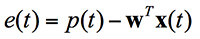
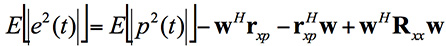
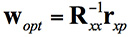
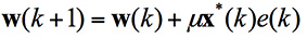
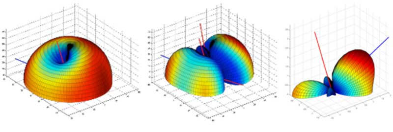
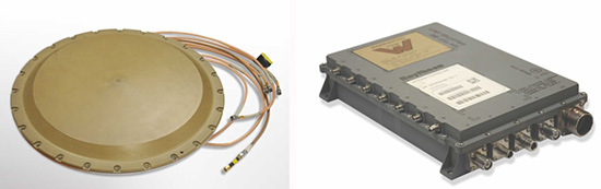
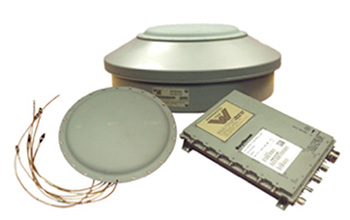
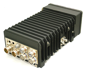


![[INSERT FIGURE 3] Figure 3 – Post seismic Vertical Deformation Movement after the 1964 Alaska Earthquake (Suito, H., and J.T. Freymueller, “A viscoelastic and afterslip postseismic deformation model for the 1964 Alaska Earthquake, J. Geophy. Res,” ArcGIS raster layer was developed using grid values obtained from website: http://www.gps.alaska.edu/jeff/SF2009_postseismic.html)](https://stage.globalpositioningnews.com/wp-content/uploads/2017/04/GPS_World_Newsletter_12_Fig_3.jpg)
![Figure 4 – GPS on Bench Mark Residuals Using Geoid12B in the State of Alaska – {GPS on BMs Residual = [GEOID12B value – (NAD 83 (2011) ellipsoid height value – NAVD 88 orthometric height value)]}. The Residuals are Depicted by Symbols (units = cm)](https://stage.globalpositioningnews.com/wp-content/uploads/2017/04/GPS_World_Newsletter_12_Fig_4.jpg)
![Figure 5 – GPS on Bench Mark Residuals Using Geoid12B in the State of Alaska –{GPS on BMs Residual = [GEOID12B value – (NAD 83 (2011) ellipsoid height value – NAVD 88 orthometric height value)]}. The Value of the Residuals are Labeled (units = cm)](https://stage.globalpositioningnews.com/wp-content/uploads/2017/04/GPS_World_Newsletter_12_Fig_5.jpg)
![Figure 6 – GPS on Bench Mark Residuals Using Geoid12B in the Haines and Skagway, Alaska, Region {GPS on BMs Residual = [GEOID12B value – (NAD 83 (2011) ellipsoid height value – NAVD 88 orthometric height value)]}. (units= cm)](https://stage.globalpositioningnews.com/wp-content/uploads/2017/04/GPS_World_Newsletter_12_Fig_6.jpg)

![Figure 7 – GPS on Bench Mark Residuals Using xGeoid16b in the State of Alaska – Referenced to IGS08 (units = cm) – {GPS on BMs Residual = [xGEOID16b value – (IGS08 ellipsoid height value – NAVD 88 orthometric height value)]}. Green Line Represents the Leveling Lines](https://stage.globalpositioningnews.com/wp-content/uploads/2017/04/GPS_World_Newsletter_12_Fig_7.jpg)
![Figure 8 – GPS on Bench Mark Residuals Using xGeoid16b in the State of Alaska – Referenced to IGS08 with a trend removed– {GPS on BMs Residual = [xGEOID16b value – (IGS08 ellipsoid height value – NAVD 88 orthometric height value)]}. (units = cm) – Green Line Represents the Leveling Lines](https://stage.globalpositioningnews.com/wp-content/uploads/2017/04/GPS_World_Newsletter_12_Fig_8.jpg)
![Figure 9 – GPS on Bench Mark Residuals Using xGeoid16b in the State of Alaska - {GPS on BMs Residual = [xGEOID16b value – (IGS08 ellipsoid height value – NAVD 88 orthometric height value)]}. Referenced to IGS08 with a trend removed (units = cm) - “up” blue arrows indicated a positive residual and a “down” red arrow indicates a negative residual](https://stage.globalpositioningnews.com/wp-content/uploads/2017/04/GPS_World_Newsletter_12_Fig_9.jpg)
![Figure 10 – GPS on Bench Mark Residuals Using xGeoid16b in the State of Alaska –– [GPS on BMs Residual = [xGEOID16b value – (IGS08 ellipsoid height value – NAVD 88 orthometric height value)]. Referenced to IGS08 with a trend removed (units = cm) – Residuals greater than 20 cm are labeled.](https://stage.globalpositioningnews.com/wp-content/uploads/2017/04/GPS_World_Newsletter_12_Fig_10.jpg)
![Figure 11 – GPS on Bench Mark Residuals Using xGeoid16b in the Matanuska-Susitna Borough, Alaska, Region – Large Difference between two relatively closely spaced stations (TT2313 and TT2332) - Referenced to IGS08 with a trend removed – {GPS on BMs Residual = [xGEOID16b value – (IGS08 ellipsoid height value – NAVD 88 orthometric height value)]}. (units = cm)](https://stage.globalpositioningnews.com/wp-content/uploads/2017/04/GPS_World_Newsletter_12_Fig_11.jpg)
![Figure 12 – GPS on Bench Mark Residuals Using xGeoid16b in the State of Alaska with an Overlay of Fault Lines – Residuals are referenced to IGS08 with a trend removed – {GPS on BMs Residual = [xGEOID16b value – (IGS08 ellipsoid height value – NAVD 88 orthometric height value)]}. (units = cm)](https://stage.globalpositioningnews.com/wp-content/uploads/2017/04/GPS_World_Newsletter_12_Fig_12.jpg)

![Figure 14 - GPS on Bench Mark Residuals Using xGeoid16b in the Matanuska-Susitna Borough, Alaska, Region with an overlay of Fault Lines – Large Difference between two relatively closely spaced stations (TT2313 and TT2332) - Referenced to IGS08 with a trend removed – {GPS on BMs Residual = [xGEOID16b value – (IGS08 ellipsoid height value – NAVD 88 orthometric height value)]}. (units = cm)](https://stage.globalpositioningnews.com/wp-content/uploads/2017/04/GPS_World_Newsletter_12_Fig_14.jpg)
![Figure 15 – GPS on Bench Mark Residuals Using xGeoid16b in Yukon-Koyukuk Borough, Alaska, region with an Overlay of Fault Lines – Large Difference between two relatively closely spaced stations (TT3571 and TT3557) - Referenced to IGS08 with a trend removed – {GPS on BMs Residual = [xGEOID16b value – (IGS08 ellipsoid height value – NAVD 88 orthometric height value)]}. (units = cm)](https://stage.globalpositioningnews.com/wp-content/uploads/2017/04/GPS_World_Newsletter_12_Fig_15.jpg)
![Figure 16 – GPS on Bench Mark Residuals Using xGeoid16b in the Skagway, Alaska, Region with an Overlay of Fault Lines - Referenced to IGS08 with a trend removed – {GPS on BMs Residual = [xGEOID16b value – (IGS08 ellipsoid height value – NAVD 88 orthometric height value)]}. (units = cm)](https://stage.globalpositioningnews.com/wp-content/uploads/2017/04/GPS_World_Newsletter_12_Fig_16.jpg)