In the July and August issues of the magazine, the “Out in Front” editorials held forth on the perfection or lack thereof in the GPS signal and service.
Now it’s your turn!
Give us your opinion at gpsworld.com/17augustpolland we’ll publish the results in the September issue. And you’ll gain entry to a random drawing for a $50 gift card.
The question is: How close to perfect is GPS performance?
And your choices are:
Absolutely perfect. 100 percent.
Nearly perfect. The space segment functions flawlessly. The only problems are with jamming and user equipment.
Almost nearly perfect. There have been a few hiccups in space, then there’s jamming, and user equipment weaknesses.
Not nearly close enough to perfect — but pretty good. The (admittedly rare) operator miscue, jamming, spoofing, and other exploitable user equipment weaknesses.
Fair, but a long way to go. All the above cited problems, plus lack of signal reception under canopy, urban canyons, indoors.
Not a passing grade. But it’s the best I have, so I grit my teeth and use it.
Pretty poor if you ask me. It just does not meet my requirements.
Other (please specify)
For background and two different views on the controversy engendered by a U.S. Air Force public release on this subject, see:
It’s almost September. For the GPS World staff, this means scramble time. We have two important industry events to attend: The venerable ION GNSS+ conference and the huge Intergeo trade show.
ION GNSS+ is the Institute of Navigation’s largest technical meeting and showcase of GNSS technology, products and services. Hundreds of papers are shared by experts in the field, in presentations and panels.
The show has changed over the years to broaden its focus to applications, and added a “+” to its name to incorporate all the positioning, navigation and timing (PNT) technology that aids GNSS in location, much as we have also done in providing a new subtitle to our magazine.
New this year are Short Courses, aimed at bringing your non-technical staff up to speed on the technology behind the industry, no matter their background. For instance, one course is “GNSS 101: An Introduction.”
Intergeo, which is held each year in different city in Germany, comes to Berlin. The huge show, attended by about 17,000 people, is a conference and trade fair (emphasis on trade fair) for the fields of geodesy, spatial data, surveying, UAVs and land management.
A hot topic at Intergeo continues to be Geospatial 4.0, the massive transformation where big data, mobility and cloud solutions are driving a new global digital economy.
Other buzzed-about topics include photogrammetry, building information modeling (BIM) and smart cities.
One important and timely topic is the need for infrastructure that ensures data security and protection. Once again, the Interaerial Solutions show for UAVs will take place as part of Intergeo.
In the battle for reliable positioning and timing, the U.S. Army is engaged in a multitude of activities, including mounted and dismounted A-PNT (assured position, navigation and timing) systems, anti-jam technology and pseudolites.
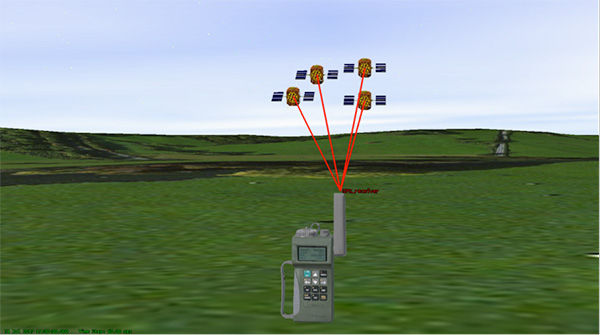
The idea is simple: Take some GPS satellites, and put them on or near the ground. Now you have a navigation system where you have full control over the locations and power of the transmissions. You can ensure that the transmissions reach places that GPS normally struggles with, such as deep urban canyons, forests and valleys.
You can turn up the transmit power, so they are much harder to jam than spaceborne GPS signals. These pseudo-satellites, commonly referred to as pseudolites, have seen steady interest over the years for a variety of applications.
Now the U.S. Army is pursuing the use of pseudolites as part of its initiative to maintain operation in GPS-denied environments.
Pseudolite Basics
There are various types, and use-cases, of pseudolites. In this column we’ll consider the direct-ranging pseudolite, which can be simply considered as a ground-based GPS satellite. If we deploy several pseudolites on the ground, we can imagine that a normal GPS receiver would be able to receive the GPS-standard transmissions and derive a position, just as we would from the space-based satellite transmissions.
The fact that the pseudolites are ground-based introduces us to the first consideration: The locations of the transmitters are no longer described by orbital parameters. Instead of calculating the position of satellites, we need to describe the location of the pseudolites in geographical terms, perhaps with a fixed position described in Earth-centered, Earth-fixed (ECEF) coordinates.
The transmitted navigation data message, which would normally contain almanac and ephemeris information, may now need to contain the geographical position of the pseudolite. Not a problem, but our GPS receivers will need a software upgrade to be able to handle this situation.
The deployment of the pseudolites themselves poses an interesting problem. Imagine a military scenario, where the army is deployed to a region of interest. Navigation warfare is taking place, and GPS is frequently jammed in the region.
High-power pseudolites are deployed to allow the army to navigate despite the jamming, using the same standard-issue GPS receivers that soldiers are familiar with.
The first problem is, having placed your pseudolites in position, how do you know where they are?
You might choose to place your pseudolites at locations that have previously been surveyed, so you know where they are in advance. But this isn’t likely, particularly if you’ve just moved your troops into an unfamiliar area. You might also want to move the pseudolites regularly, as the army moves to new ground. So the pseudolites need to determine their own position, and the easiest way for at pseudolite to determine its own position is with GPS, of course.
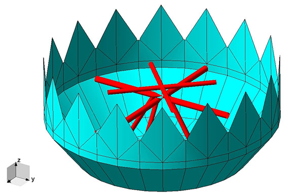
Isn’t this a bit incestuous? If we’re using pseudolites because GPS is jammed, how does the pseudolite get its position? This is why military pseudolites will typically be fitted with some form of anti-jam technology, such as a controlled radiation pattern antenna. This allows the pseudolite to receive GPS satellite signals in the presence of jamming, determine its own position, and transmit that as part of its own navigation message.
So, now that we can get pseudolite locations, the next consideration is: Where should pseudolites be placed?
A-DOP-ting a Good Layout
If you know about GNSS, you’ll be familiar with the concept of dilution of precision (DOP). This is essentially a measure of how accurate your position estimate is likely to be, due to the geometry of the satellites: a good wide spread of satellite positions gives us better accuracy.
Figure 1. Poor satellite geometry, resulting in high DOP. (Image: Michael Jones)Figure 2. Good satellite geometry, resulting in low DOP. (Image: Michael Jones)
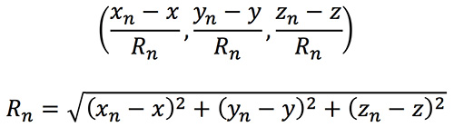
The DOP can be easily calculated by forming a covariance matrix of the geometry, expressed in an appropriate coordinate frame. If (xn, yn, zn) denotes the position of the nth pseudolite, and (x, y, z) the position of the receiver, we can express the unit vectors from the receiver location to the pseudolite location:
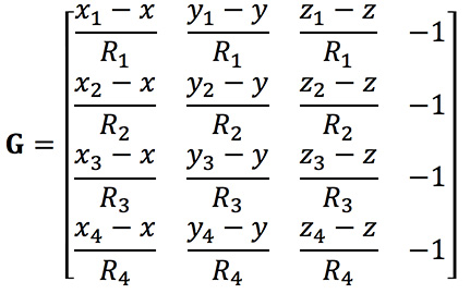
We then form a matrix of these unit vectors:
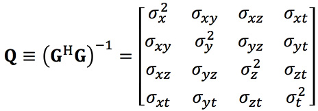
Finally, we form the covariance matrix from which we can extract the DOP values:
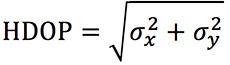
From the elements of this matrix we can determine the various DOP metrics. Let’s concentrate on horizontal DOP (HDOP), given by:
When positioning using GPS satellites, we are blessed with a Walker constellation that generally gives us a nice spread of satellite locations (unless we’re in an urban canyon). On the battlefield, using pseudolites, we do not have the same luxury.
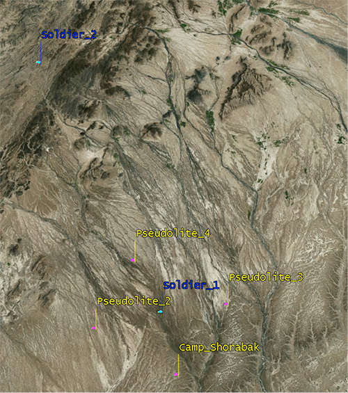
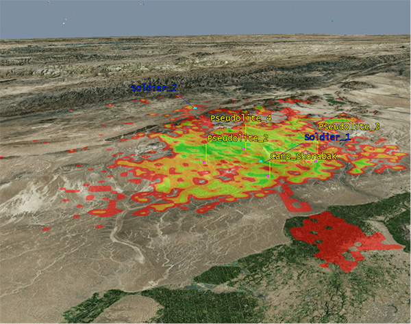
Let’s consider a scenario: a conflict in Helmand province, Afghanistan. An operating base is established at Camp Shorabak, where a pseudolite is operating, and three further pseudolites are deployed in the field. This is shown in figure Figure 3.
Figure 3. Scenario with four pseudolites. (Image: Michael Jones)
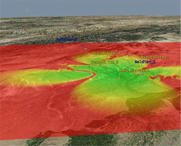
Taking a look at Figure 4, we can see what this means for HDOP. The regions shaded green represent locations where our HDOP is less than 2.5, and the red areas represent an HDOP greater than 50.
Soldier #1 is surrounded by the four pseudolites, which is a pretty nice arrangement: We get an HDOP of around 2.4. But if we now consider soldier #2, located a bit further out, we get a very different picture.
Here we have an HDOP of 64, which is fairly terrible. It’s not really that surprising looking at the geometry — to soldier #2 the pseudolites all appear in a similar direction. Soldier #2 cannot expect to achieve good positional accuracy in this arrangement.
Figure 4. HDOP for the Afghanistan scenario. (Image: Michael Jones)
So getting a good geometric spread of ground-based pseudolite locations could be a bit of a challenge, especially if the operating area is constantly moving and changing. The next thing to think about is getting enough height.
Getting the Height Right
When we perform positioning using GPS, we typically track several satellites, which have a range of elevations. Many GPS receivers will choose to ignore the satellites at low elevations, such as those within 5 degrees of horizontal, because those satellites are generally the least reliable. They may be partially obscured, and subject to more noise and fading.
Ground-based pseudolites all have very low elevations by definition. Unless the terrain is perfectly flat and smooth, pseudolites quickly become obscured. Even with flat ground, pseudolite signals will disappear behind the horizon after a few kilometers.
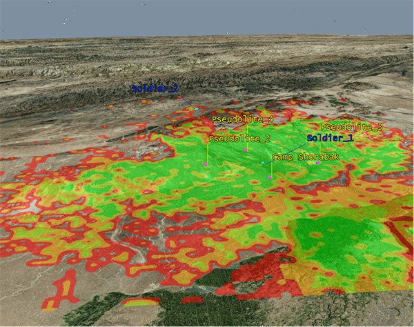
Let’s go back to our Afghanistan scenario again. This time, instead of looking at DOP, let’s look at the geographical coverage of our four pseudolites. Here we’ll assume that our user, the soldier, is 2 meters (m) high, and the pseudolite antennas are mounted at a height of 20m above the ground. That’s pretty high — the army will need to erect some masts.
Figure 5 shows what we get. The green areas are locations where our soldier can see all four pseudolites; yellow three, orange two, and red one. At all other locations, no pseudolite signals can be seen at all. You can quickly see that the range isn’t great — terrain, even small undulations in the ground, is a line-of-sight killer. Add some buildings and trees and the situation gets worse. Reduce the height of our pseudolites below 20m, and the situation gets worse. Soldier #1 can receive three pseudolite signals, but soldier #2 has no hope in this case.
Figure 5. Pseudolite visibility at 20m antenna height. (Image: Michael Jones)
Let’s raise the height of the antennas to a fairly crazy 100m above ground (Figure 6). As expected, we get much better coverage, but soldier #2 still has a problem. To get good signal coverage over any sizable area, you really do need to get those antennas as high as possible.
Figure 6. Pseudolite visibility at 100-m antenna height. (Image: Michael Jones)
Augmenting GPS
Often, we don’t want to rely on pseudolite signals alone. If GPS is available, we clearly want to make use of it, and so we want to use a mixture of both GPS satellites and pseudolites. Consider working in a region of sporadic GPS reception, such as an urban environment or forest. We can usually receive a couple of good GPS satellites, but we also need a couple of pseudolites to help us get a complete navigation solution.
Coming back to one of our original objectives, which is to avoid redesigning the GPS receiver hardware, we need to make sure that our receivers can receive and process both GPS satellite signals and pseudolite signals simultaneously. To achieve this, we can decide to make our pseudolites transmit GPS-standard signals, and make use of unassigned spreading codes to essentially create new satellites in the constellation.
But we quickly run into a problem. GPS satellites are always a distance of around 20,000 kilometers away, and the received signal strength is also fairly constant: around –158.5 dBW. This is a very small signal, as we all know, sitting well below the noise floor. When we suddenly bring high-power pseudolites into the mix, we have quite a nasty problem to deal with.
Near, Far, Wherever You Are
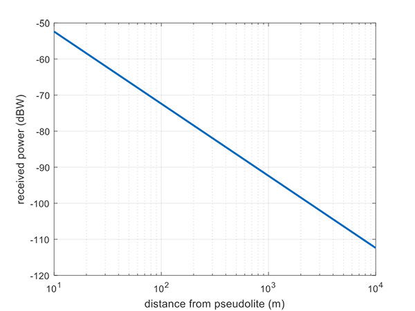
Let’s say, for argument’s sake, we have a pseudolite transmitting with a power of 1 watt. Conducting a basic link budget analysis gives us the plot below and suggests that, at a distance of 10 km from the pseudolite, we can expect to receive the signal at around –112 dBW. This is way above our GPS satellite signal level, but might be manageable by a receiver. Now consider a receiver at a distance of 100 m from the transmitter: we receive a power of –72 dBW, which is huge.
In our quest to augment GPS and make it more robust, we have in fact created a GPS jammer, and achieved exactly the opposite. As with any radio communications link, the received power is extremely sensitive to the distance (varying with the square of distance). In pseudolite terminology, this is known as the near/far problem.
Figure 7. Theoretical received power for a 1-W pseudolite, under ideal conditions. (Figure: Michael Jones)
The near/far problem has given engineers headaches for quite some time. Essentially, the problem comes down to: How can our GPS receivers handle such a massive dynamic range of expected signals? Especially if our objective is to avoid modifying the GPS receiver hardware, if at all possible.
How can a receiver handle the high power of a close-up pseudolite, which is to all intents a jammer, whilst simultaneously receiving the tiny GPS satellite signals from space? Various solutions have been proposed over the years, but one of the current favorite techniques involves pulsing the pseudolite signal.
The idea, then, is to only turn on the pseudolite periodically, essentially applying a duty cycle to the transmission. If a pseudolite isn’t transmitting, it can’t interfere with the normal GPS signals. There are a couple of things to take into consideration here:
What should the pulse duty cycle be, to enable both satellites and pseudolites to be tracked?
How does the GPS receiver behave when presented with alternating large and small signals?
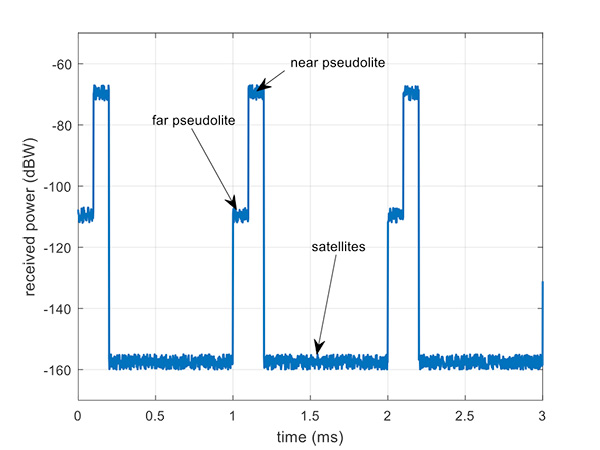
A mathematical analysis of duty cycle effects is beyond the scope of this column, but consider Figure 8 for a qualitative view. Here we have two pseudolites operating alongside GPS satellites. The duty cycle chosen here is for the pseudolite to be operational for 10% of a 1 millisecond integration period. This gives enough time, when the pseudolite is not transmitting, for the low-level GPS satellites to be tracked.
The second pseudolite, which is closer and therefore higher power, transmits for a further 10% slot after the first pseudolite. You can see that each additional pseudolite eats into the time available for tracking GPS satellites, and degrades the signal-to-noise ratio. There are some tricks you can play, such as transmitting multiple pseudolites at the same time if you know they will be similar power levels, but it can get complicated.
Figure 8. Received power versus time, for a pulsed pseudolite scenario. (Figure: Michael Jones)
The Importance of Gain Control
How the receiver copes with the large differences in received power level depends largely on the design of the RF front-end in the receiver. Most GPS receivers will have a certain amount of automatic gain control (AGC), which is a feedback loop designed to keep power levels constant. Many GPS receivers, though, simply aren’t designed with enough AGC to handle pseudolite-level signals (think GPS jammers again).
Military receivers, though, tend to have greater RF handling capabilities, and more bits in the ADC, so are better-suited to the situation. It is then a question of making sure the AGC loop responds in an appropriate time, compared to the duty cycle of pulses.
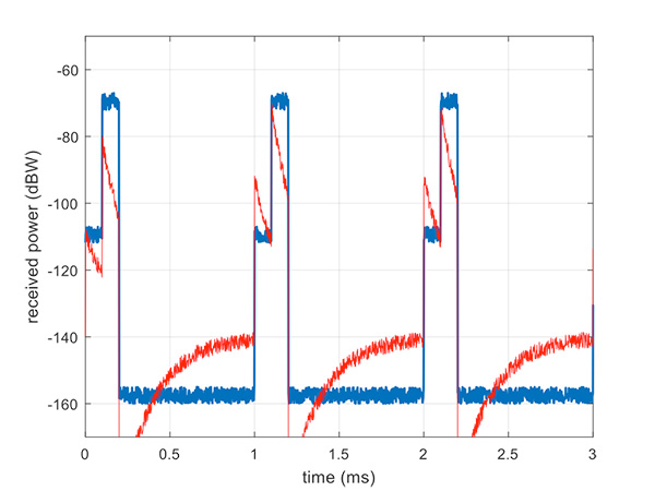
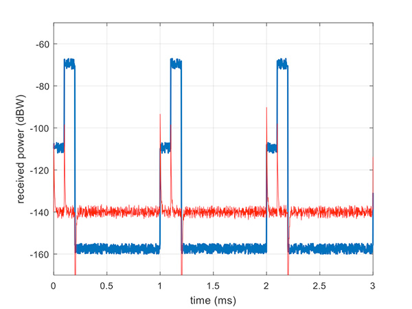
Figure 9 illustrates a slow AGC response, which is not particularly suitable. Compare this with Figure 10, where we have a fast AGC response, quickly adapting to the switches in power level. A receiver with this characteristic will be better able to track both pseudolite and satellite signals.
Figure 9. Pulsed pseudolites with slow AGC response (in red). (Figure: Michael Jones)Figure 10. Pulsed pseudolites with fast AGC response (in red). (Figure: Michael Jones)
Airborne Pseudolites
If you’ve read this far, you’ll now know that the main problems with ground-based pseudolites are lack of good geometry, signal blocking by terrain, and the horrendous near/far issues. Wouldn’t it be nice if we could raise the pseudolites to a really high altitude, and all these problems would go away? Wait, that’s the GPS satellite constellation!
Ok, let’s not put them that far up. But how about carrying pseudolites on high-altitude airborne platforms instead? Great idea, and that’s why this is a current thread of defense activity in various countries. High-altitude long-endurance (HALE) or HAPS (high-altitude pseudo-satellite; the clue is in the name) unmanned platforms can be used to carry pseudolites at high altitude.
This solution can provide excellent coverage, the pseudolites can be repositioned as necessary, and the near/far problem is also far less pronounced.
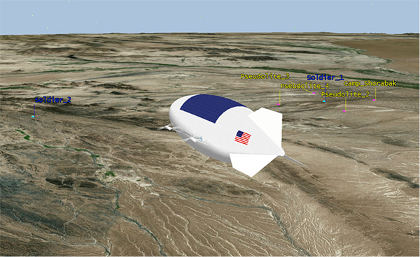
I leave you once again with our Afghanistan scenario, from the point of view of a high-altitude airship at 18,000 meters.
Figure 11. High-altitude platform, potentially carrying a pseudolite at 18,000 m. (Image: Michael Jones)
Dana Goward President, Resilient Navigation and Timing (RNT) Foundation
An apparent mass GPS spoofing attack in June involved more than 20 vessels in the Black Sea and suggests that Russia may be aggressively experimenting with signal disruption and spurious substitution.
“GPS equipment unable to obtain GPS signal intermittently since nearing coast of Novorossiysk, Russia. Now displays HDOP 0.8 accuracy within 100m, but given location is actually 25 nautical miles off…”
Subsequent dialog with the ship’s master and examination of various documents and screen grabs he furnished enabled navigation experts to conclude this was a fairly clear case of spoofing: sending false signals to cause a receiver to provide false information. Other vessels in the vicinity experienced the same problem.
The RNT Foundation has received numerous anecdotal reports of maritime problems with the automatic identification system (AIS), a tracking system used for collision avoidance on ships, and with GPS in Russian waters, though this is the first well-documented public account.
Russia has very advanced capabilities to disrupt GPS. More than 250,000 cell towers in Russia have been equipped with GPS jamming devices as a defense against attack by U.S. missiles. And there have been press reports of Russian GPS jamming in both Moscow and the Ukraine. In fact, Russia has boasted that its capabilities “make aircraft carriers useless.”
The U.S. director of National Intelligence issued a report on May 11 that states that Russia and other actors are focusing on improving their capability to jam U.S. satellite systems.
Assuming Russia is behind this, why would they do such a thing? Possibly to encourage use of GLONASS or their terrestrial loran system, Chayka, instead of GPS. Possibly for some security reason known only to them.
Whatever the reason, it reminds us of the vulnerability of GPS signals, and of the plethora of motives that “bad actors” — governmental or private criminal interests — may have to disrupt and deceive GNSS users.
And of the U.S. Coast Guard’s advice about GPS and all satnav: “Trust But Verify.”
Dana Goward is president of the Resilient Navigation and Timing Foundation. He is the proprietor at Maritime Governance LLC. In August 2013, he retired from the federal Senior Executive Service, having served as the maritime navigation authority for the United States. As director of Marine Transportation Systems for the U.S. Coast Guard, he led 12 different navigation-related business lines budgeted at more than $1.3 billion per year. He has represented the U.S. at IMO, IALA, the UN anti-piracy working group and other international forums. A licensed helicopter and fixed-wing pilot, he has also served as a navigator at sea and is a retired Coast Guard Captain.
A: Integration with GNSS and other sensors in most every military vehicle or weapon-control system will enable inertial sensor developers to focus on driving improvements in performance for the two fundamental parameters that a sensor-fusion INS filter cannot estimate: noise and in-run bias stability. Ultra-tightly coupled sensor fusion of GNSS with range-, speed- and video position-sensing, with tactical and navigation grade inertial sensors optimized for noise and in-run, will enable design of robust GPS chip-level solutions for high-dynamic, high-performance navigation for nearly any military environment or engagement.
Michael Whitehead, chief technology officer, Hemisphere GNSS
A: Previously used for military applications, inertial technology has become mainstream as performance-to-cost has improved with the emergence of low-cost microelectromechanical systems (MEMS). Precise point positioning (PPP) advancements have driven GNSS accuracies to 4 cm or better, but long PPP initialization times are problematic in challenging environments where reconvergence is often required. Tightly coupled integration of PPP and navigation-quality MEMS will overcome limitations of both technologies, yielding high accuracy with high availability, even in challenging environments.
Chris Wheeler, manager, telematics and connected sites, Trimble Navigation
A: The availability of multi-frequency GNSS receivers with inertial components on a small lightweight board can now deliver centimeter-accurate INS/GNSS solutions, so that OEMs and integrators can significantly improve reliability and robustness in harsh or GNSS-denied applications or for solutions such as UAVs. The advances provided by MEMS inertial components increase overall efficiency by reducing the number of ground control points while still meeting the needs for a low weight and power consumption solution.
My last column highlighted some of the feedback provided by guest presenters at the NGS’ 2017 Geospatial Summit held on April 24-25 in Silver Spring, Maryland. That column also provided a discussion on the approximate differences between NAPGD2022 and NAVD 88 (and NGVD 29) at a national and local level. It was mentioned that to prepare for the new datums and develop implementation plans, users should obtain an understanding of the differences between NAPGD2022 and NAVD 88. The last column provided figures that depicted the approximate absolute and relative differences between the new vertical reference frame, North American-Pacific Geopotential Datum of 2022 (NAPGD2022) and NAVD 88. This column is the second in a new series of columns addressing topics associated with transitioning to the new North American-Pacific Geopotential Datum of 2022 (NAPGD2022).
The name of the National Geodetic Survey’s new vertical reference frame is the North American-Pacific Geopotential Datum of 2022 (NAPGD2022). So, what is a geopotential model? The following is the definition of a geopotential model from Wikipedia: “In geophysics, a geopotential model is the theoretical analysis of measuring and calculating the effects of Earth’s gravitational field.” [See the box titled “Definition of geopotential and geopotential model from Wikipedia.”]
Definition of geopotential and geopotential model from Wikipedia
In order for a height to a have physical meaning, the height system must have some relation to the Earth’s gravity field. Basically, for geodesists, a geopotential model is a way of measuring the effects of Earth’s gravitational field and the means to deriving a geoid model. So, what does the Earth’s gravity field look like? The box titled “Static Gravity Field – Anomalies” is a good image of the Earth’s gravity field created by the GRACE program.
It was mentioned in the last column that stakeholders across the federal, public and private sectors provided feedback and impacts of NGS New 2022 Datums on their products and services. All of these presentations are now available on NGS’ website. [See box titled “Website that contains the NGS 2017 Geospatial Summit Presentations.“] NGS did an excellent job of recording these presentations. The website allows the user to download the video and/or slides, as well as watch the presentations on their computer.
Many surveyors and mappers will be providing services to Federal, state, and local agencies to assist them in their transitioning activities. I would encourage all users to watch the presentations by the partners to obtain an understanding of how these agencies’ products and services are going to be effected by a datum change. For example, the presentation by the Federal Emergency Management Agency (FEMA) can be found here.
This column will focus on two of the presentations by NGS employees – “Modernizing the Geopotential or Vertical Datum” and Monitoring Changes in the Geoid.” These two presentations are very important to obtaining an understanding of NAPGD2022. [See box title “NGS Presentation at the 2017 Geospatial Summit – “Modernizing the Geopotential or Vertical Datum.”]
Slide 33 from the presentation titled “Modernizing the Geopotential or Vertical Datum” depicts the relationship between the ellipsoid, geoid, and orthometric heights. (See box titled “Slide 33 From “Modernizing the Geopotential or Vertical Datum.”)
A previous column discussed how NGS developed their scientific and hybrid geoid models. The NAPGD2022 will begin with the best 3-dimension geopotential model available and derive the most accurate geoid model, e.g., GEOID2022, for establishing NAPGD2022 GNSS-derived orthometric heights. Just like NAVD 88 leveling derived heights need accurate gravity values to compute accurate orthometric heights and height differences, the geopotential model needs accurate, current gravity data to estimate local variations in the global model. The bottom line is that an accurate geopotential model is necessary for deriving an accurate geoid model that is necessary for establishing accurate GNSS-derived orthometric heights and height differences.
In the presentation “Modernizing the Geopotential or Vertical Datum,” Monica Youngman discussed the NGS project called “Gravity for the Redefinition of the American Vertical Datum (GRAV-D).” The goal of GRAV-D is to create a gravimetric geoid accurate to 1 cm where possible using airborne gravity data. The overall target is to enable users to obtain 2-cm accuracy orthometric heights from GNSS and a geoid model. View this website for more information on GRAV-D.
Once a geoid model is computed, e.g., GEOID2022, it will need to be validated to estimate the accuracy of the derived product. What does this mean to surveyors and mappers? In my opinion, the NAPGD2022 will help the surveying community maintain a vertical reference frame that’s reliable and traceable. Saying that, it is extremely important to know the relative accuracy of the geoid model used to establish GNSS-derived orthometric heights in NAPGD2022. As mentioned in my April column, NGS is performing geoid slope validation surveys (GSVS) to evaluate the current experimental geoid models being developed using GRAV-D data. In the presentation “Modernizing the Geopotential or Vertical Datum,” Derek Van Westrum discussed the GSVS projects. Evaluation of the experimental gravimetric geoid model is critical to the implementation of NAPGD2022 and should be part of a transition plan to the NAPGD2022. Performing a geoid slope validation project similar to NGS may be too expensive to be performed by most agencies. However, some agencies may be able to perform low budget geoid slope evaluation surveys. These surveys could include performing combined GNSS and leveling surveys to evaluate the relative accuracy of the gravimetric geoid model in areas that require accurate orthometric heights. Performing several of the gravimetric geoid evaluation surveys in major cities and/or areas that require accurate heights would help to facilitate the implementation of NAPGD2022.
These types of geoid evaluation surveys should be performed in areas of the country that are influenced by crustal movement. For example, in southern Louisiana and other parts of the Gulf Coast of the United States that are being influenced by subsidence (https://www.ngs.noaa.gov/heightmod/NOAANOSNGSTR50.pdf, https://www.ngs.noaa.gov/PUBS_LIB/Subsidence_at_Houston_Texas_TR_NOS131_NGS44.pdf). There is no doubt that NAPGD2022 will provide a more efficient and cost-effective way to maintain consistent and accurate orthometric heights; however, evaluating the relative accuracy of the geoid model is critical to a successful implementation of NAPGD2022.
The first phase of the GRAV-D project is the airborne gravity survey of entire country and its holdings; the second phase is the long-term monitoring of the change in the geoid. Not only is the NAVD 88 being replaced with a new datum but the geoid model, the underlying foundation of establishing GNSS-derived orthometric heights in NAPGD2022, will be constantly changing. The geoid will change but it will change very slowly. Saying that, it is still important for NGS to monitor changes in the geoid if users are going to establish and maintain GNSS-derived orthometric heights at the centimeter level. As part of the modernization of the vertical reference frame, NGS has outlined four components of a long-term monitoring plan. [See box titled “Components of a Long-Term Monitoring Plan.”]
Components of a Long-Term Monitoring Plan
(From presentation titled “Monitoring Changes in the Geoid” given by Dr. Theresa Damiani at the NGS 2017 Geospatial Summit)
What and Where to Monitor
How to Monitor in the Near-Term (next 1 to 3 decades)
Which Products Need to be Available
Long-Term Program Adaptation
The two most important components of the plan, in my opinion, are “What and Where to Monitor” and “How to Monitor in the Near-Term.” There are small changes in the geoid that occur over long periods of time. [See box titled “Slide 5 from presentation titled “Monitoring Changes in the Geoid.”]
Slide 5 from presentation titled “Monitoring Changes in the Geoid”
(From presentation titled “Monitoring Changes in the Geoid” given by Dr. Theresa Damiani at the NGS 2017 Geospatial Summit)
Dr. Damiani presented a slide that outlined NGS’ vision for vertical datum products as they are related to the geoid model. [See the box titled “NGS’ Vision for Vertical Datum Products, 2022 +.”] NGS will be publishing both static geoid models (S) and dynamic geoid models (D). The “S” static model will be a typical geoid model, aimed to capture the 1 cm-accurate model at a specific epoch, and the “D” dynamic model will capture the rate of change of the geoid at all places. Dr. Damiani mentioned in her presentation that NGS has initiated a program called “The Geoid Monitoring Service.” This service is a new project, initiated in January 2017, that is planned to be operational and produce NGS’ first “D” dynamic geoid by 2022.
NGS’ Vision for Vertical Datum Products, 2022 +
(From presentation titled “Monitoring Changes in the Geoid” given by Dr. Theresa Damiani at the NGS 2017 Geospatial Summit)
➢ In 2022, NGS will release “S” and “D” geoid models: static (S) and dynamic (D).
➢ The “S” static will be a typical geoid model, aimed to capture the 1 cm-accurate model at a TBD epoch.
➢ The “D” dynamic will capture the rate of change of the geoid at all places. In 2022, it will capture at least the continuous, permanent change signals such as Glacial Isostatic Adjustment (GIA).
➢ Both models will be integrated into OPUS, mostly invisible to users. Orthometric heights provided by OPUS will be time-sensitive, so that they are the combination of the static geoid model plus the geoid rate of change indicated by the dynamic model.
➢ NGS will provide separate tools to directly access both the “S” and “D” models.
This column discussed the basic foundation parameters of the North American-Pacific Geopotential Datum of 2022 (NAPGD2022); that is, a global geopotential model, the GRAV-D project, and the GEOID2022 geoid model. It emphasized that NAPGD2022 will provide a more efficient and cost-effective way to maintain consistent orthometric heights, but evaluating the relative accuracy of the geoid model is critical to a successful implementation of NAPGD2022. Performing GNSS/Leveling evaluation surveys will help in evaluating the relative accuracy of GEOID2022. NGS is developing geodetic routines and tools to assist users in transforming heights from NAVD 88 to NAPGD2022, and enabling the incorporation of geodetic leveling data into NAPGD2022 to establish NAPGD2022 orthometric heights. Future columns will address some of these tools and routines.
Possibly during the course of last month’s editorial here, “‘Nearly Perfect’ Not Nearly,” in which I called out the U.S. Air Force for lauding itself a bit much, I veered across the line separating vehemence from over-vehemence. Just possibly. Over-vehemence is a professional hazard of journalism. A gentle reader wrote in to suggest as much. He began, in his polite way, with “As always, I enjoyed your article and it made me think.” Then he offered a few of his thoughts for me in turn to consider.
First, he urged me to weigh all three GPS segments. The space and control segments operate almost flawlessly, he averred. Except, I can’t refrain from riposting, for the times that they don’t.
The user segment, we can all agree, is a different story. Most current GPS user equipment can be jammed and spoofed, sometimes very easily, and some have difficulty handling leap seconds and GPS week rollovers.
The U.S. Air Force and the GPS program office cannot fix the problem with user equipment. This is up to those who manufacture, purchase, install and maintain the user equipment.
Fair enough.
Let’s not even get into mapping and guidance algorithms and obsolete data that generate multitudinous stories in mass media about drivers led astray and into danger “by GPS.” Those are the fault, not of the user equipment per se, but of software conjoined to a receiver in a navigation device or smartphone.
My column in June’s GNSS Design & Test enewsletter covered the same ground and then tackled the potential costs of GPS disruption, citing a study done by Innovate U.K., the U.K. Space Agency and the Royal Institute of Navigation. This included a pie chart of potential economic losses in the U.K. that would stem from a prolonged GNSS disruption. I really should have correleated these with, or at least mentioned in the same breath, the reports done for the National Space Based-PNT Advisory Board by Irv Leveson, because there were several mismatches. In particular, the PNT Advisory Board study concluded that more than 50 percent of the value of GPS to the U.S. economy lies in high-precision uses — substantially higher than estimated in the U.K.
Regardless of statistics, we should think, my correspondent reminded me, about the performance needs of different uses. It’s not just whether you have PNT or you don’t. The degree to which you have it is the key: accuracy, coverage, 3D versus 2D positioning and other factors determine if a technology can perform to meet a given need. Aviation requires 3D positioning for some operations. Surveying and machine control require submeter accuracy. Road use requires meter accuracy now, and submeter in the future for autonomous driving. Almost 50 percent of the U.K. pie chart, and more than 50 percent of GPS value to the U.S., requires meter or better accuracy. Except for other satnav systems, what known technology can provide this kind of performance over an area the size of a nation, whether U.K. or U.S.?
Contributing Editor Tony Murfin is on vacation this month. In place of his column, we bring you an advance look at an important UAV show as applied to surveying and mapping, and a story about drone use in surveillance.
In the zone
Legal issues, international market analyses and best practices will take center stage at the Interaerial Solutions Expo (IASEXPO), which will take place Sept. 26–28 in conjunction with Intergeo 2017 in Berlin, Germany.
At IASEXPO, the international UAV sector will be demonstrating the potential for civil and commercial UAV applications. IASEXPO will consist of an exhibition, forum and the FlightZone for UAV demonstrations. About 150 providers from 25 countries are expected to represent the young drone market at the IASEXPO.
IASEXPO’s practical forum will cover the latest topics with renowned experts. Visitors don’t have to walk far to switch between market overviews and expert presentations. The aim is to efficiently combine the trade fair and talks.
IASEXPO Forum 2016.
Regulations. As Germany’s drone regulations come into force this year, the legal aspects of using and operating UAVs is a key focus of the practical forum. Multicopters and drones weighing more than two kilograms can now only be flown in Germany by someone who holds a “drone driving license.” Pilots will be able to take the drone license test at the trade fair.
Frank Wichert from project management company procow will detail the requirements and reveal the precise procedure that pilots must follow. Speaker Ulrich Dieckert is a lawyer and expert on the approval process; he specializes in exceptions to operating bans that hinder drone work.
Market prospects. Kay Wackwitz, CEO of Drone Industry Insights, will present economic analyses of application opportunities and limits for UAVs, and discuss market developments and collaborations.
UAV Issue Manager Ralf Heidger from German traffic control (DFS) will discuss how DFS tackles the challenge of drones in the air space and tracking them within the air-traffic-management system.
Best practices. First-hand reports will provid examples of best practices in using drones for surveying and inspecting buildings and industrial complexes. Friedrich Wilhelm Bauer from Hannover University of Applied Sciences and Arts will highlight use of thermal-imaging technology for inspections. Benjamin Federmann from Aibotix-Leica will discuss the economic benefits of using drones in surveying and construction.
The German Association of Copter Pilots will weigh the question of whether to “make or buy” needed drones and services. Answers come from success stories in niche segments such as 3D modeling and smart framing. Maik Neuser from Westnetz and Carlo Zgraggen from Aeroscout will discuss inspections in the energy sector.
Other topics will be the use of drones in agriculture, forestry and disaster relief. Antoine Cottin from Carbomap and Bobby Vick from Precisionmapper will speak to the practical forum on drones used for surveying forests.
Drones on patrol
UAVs will soon be a common sight over border zones, crime hotspots and city streets in South Africa, as public safety and security officials and police departments discover the cost saving and efficiencies offered by drone patrol “armies,” according to Airborne Drones, a South African-based manufacturer of enterprise-grade drones.
Airborne Drones Vanguard 35-km long range surveillance drone ready to take flight. (PRNewsfoto/Airborne Drones)
Drones provide a solution to the limitations of other surveillance methods such as GPS tracking, CCTV camera observation, biometric surveillance and ground patrols. Aerial surveillance is increasingly being harnessed for security monitoring — traditionally, with costly helicopters. Drone surveillance present an faster and cheaper method of data collection.
Specialized security drones can enter narrow and confined spaces, produce minimal noise, and can be equipped with night-vision cameras and thermal sensors, allowing them to provide imagery that the human eye is unable to detect. In addition, UAVs can quickly cover large and difficult-to-reach areas, reducing staff numbers and costs, and don’t require much space for operators.
Autonomous, long-range security drones are at the vanguard of new policing methods, accoring to Airborne Drones. “Offering live video feeds to ground control stations, these drones can range autonomously over pre-programmed flight paths for extended periods of time, allowing for ongoing routine patrols across wide areas such as borders, maritime regions and high security installations.
Should an incident be detected, ground crews can then follow objects or intruders from a safe distance, providing visual support to safety and security teams. UAVs can provide detailed visual documentation of sites, enabling effective analysis, risk management and security planning.”
Around the world. Numerous countries are rolling out security drones to support public safety and defense initiatives”, says Airborne Drones. Israel has long harnessed advanced drones for military surveillance, and recently sold a fleet of “spy drones” to the Irish army.
The U.S. FBI has used drones for surveillance and tracking for several years. In Australia, the new $50 million Defence Cooperative Research Centre will develop long-range drones, automated vehicles and robots to help Australian soldiers fight the wars of the future. India is looking to military-grade UAVs for maritime and other surveillance and intelligence gathering.
In June, Brazil’s São Paulo became the first Latin American city to use drones for public security surveillance, and in July, Hamburg, Germany, deployed surveillance drones for the estimated 100,000 demonstrators at the G20 summit. In Australia’s New South Wales, the authorities are using helicopter and drone surveillance along the coast to protect holiday-goers from rip currents and sharks.
UAVs are also instrumental in managing transport infrastructure safety and security and event security, from event security infrastructure to spectator and crowd control and safety, to overall health and safety planning.
International Cartographic Conference much more than just cartography
I’ve always been a strong proponent of good cartography since my early days in geographic information systems (GIS) when I saw countless examples of very poor GIS map products. Regrettably, many early practitioners of GIS understood the software but lacked an appreciation and understanding of the good cartographic principals that are absolutely necessary to communicate spatial data well.
Consequently, the International Cartography Conference (ICC 2017) was an event I didn’t want to miss, especially since this was the first time in 39 years that this prestigious conference has been held in the United States.
The 28th annual International Cartographic Conference, ICC 2017, was held in Washington, D.C., July 2-7 with moe than 1,000 attendees from 80 countries representing government, academia and international companies.
Dr. Anderson was a research scientist and executive with the U.S. Geological Survey (USGS) for 35 years and is now the executive director of CaGIS and a faculty member of the College of Charleston. Lynn Usery is a senior scientist of the U.S. Geological Survey (USGS) and director of the Center of Excellence for Geospatial Information Science. ICC events have been key activities of the International Cartographic Association (ICA).
George Washington, First in the Arts of Mapmaking
In a keynote address, Director Robert Cardillo from the National Geospatial-Intelligence Agency (NGA) explained the interesting history of NGA citing George Washington, surveyor and mapmaker, as NGA employee number one.
Washington also appointed the nation’s first geographer and father of military mapping, Robert Erskine, whose work helped win the American Revolutionary War.
He also spoke of the Civil War use of manned balloons with telegraph wires tethered to the ground, used to verbally aim indirect artillery defilade fire. He continued the history lesson up to modern times, leading to imagery and Big Data.
Other keynote speakers included: Tom Patterson, senior cartographer, U.S. National Park Service; Lee Schwartz, geographer, U.S. Department of State; and Mikel Maron, Mapbox, OpenStreetMap Foundation.
Among the many interesting presentations was one from Payam Tabrizian, Anna Petrasova and Vaclav Petras, all Ph.D. candidates at North Carolina State University and special guests of CaGIS. They demonstrated their unique physical 3D sandbox system using low-cost gaming scanners and GRASS GIS.
Imagine being able to hold a GIS in your hands: feel the shape of the earth, sculpt its topography, and direct the flow of water.
This open-source interface physically, interactively manifests geospatial data, making GIS more intuitive and accessible for beginners, and creating new opportunities for developers. It consists of a near real-time feedback cycle of interaction, 3D scanning, point-cloud processing, geospatial computation and projection.
Peer Review
Although the word cartography was dominant, the conference covered a much broader range of topics, with a heavy emphasis on GIS and the science of mapping spatial data.
Dr. Anderson reminded me that the conference is an outgrowth of the International Journal of Cartography, published on behalf of the ICA. The publication is a peer-reviewed journal, and much of the conference provides an opportunity for originators to present their work to a live audience.
The conference ran from July 3-7 with more than 600 presentations and sessions. There were also several days of pre-conference meetings and field trips in the D.C. area. My colleague, William Tewelow, who has taken over my monthly Geointelligence Insider column, and I were both overwhelmed with the number of presentations.
William was only able to attend part of the conference, but found a wealth of new material to digest and write about during the coming year.
To give you an idea of the scope, below is a list of ICC Commissions (special interest groups), with each holding dozens of break-out sessions:
Art and Cartography
Atlases
Cartographic Heritage into the Digital
Cartography and Children
Cartography in Early Warning and Crisis Management
Cognitive Issues in Geographic Information Visualization
Education and Training
Generalization and Multiple Representation
Geospatial Analysis and Modeling
GI for Sustainability
History of Cartography
Location Based Services
Map Design
Map Production and Geoinformation Management
Map Projections
Maps and Graphics for Blind and Partially Sighted People
Maps and the Internet
Mountain Cartography
Open Source Geospatial Technologies
Planetary Cartography
SDI and Standards
Sensor-driven Mapping
Topographic Mapping
Toponymy
Ubiquitous Mapping
Use, User and Usability Issues
Visual Analytics
You can read the session abstracts through the online schedule. Additionally, ICC smartphone apps permit the download of text and some PowerPoint presentations. Go to your app store and search for and install “ICC2017.”
Once you install the app, you can search for topics or presenters. You can view most presentation summaries, and even view or download some PowerPoint presentations and PDFs. (I’m not sure how long these will be available, so act soon).
Expo and Posters
The ICC featured several map/poster areas including a collection of maps created by children from around the world. Also included was an expo area with booths from organizations and businesses.
Since this was a more academic conference that fell between GEOINT and the Esri User Conference, geospatial businesses were lightly represented. Below are video clips of some of the exhibitors.
Jill Saligoe-Simmel of MapDiva demonstrates Ortelius map design software for the Mac:
Liu Xiang Ming and Tao Wang of Top MAProducts at Qingdao Geotechnical Investigation & Surveying Research Institute. The comprehensive geoscience research institute focuses on geotechnical investigation, surveying, GIS and map culture. Ming and Wang were displaying some unique gift items with mapping themes. If you know someone with a gift shop or need some unique trade show or conference gifts, email Top MAProducts at [email protected].
All in all, this was a very robust conference that I wish I could have seen more of. Lynn, Eric and the organizing committee did a superb job with such a complex effort.
Here there be dragons. That phrase (or a variation of it) was used by early mapmakers to designate the unknown — and alert sailors to the danger of traveling into uncharted waters.
I’ve always admired explorers who dared to push the boundaries of the known world. We’ve moved from the Age of Exploration to the Age of Information, but exploration continues on frontiers big and small.
Today, of course, most people think of the world as having been mapped. They can simply call up Google maps on their smartphone and see not only the world, but their town, their street and their house — in representational cartography (traditional map), satellite imagery, or even street-view imagery.
Professionals in geographic information systems (GIS) know better. The world is still a mystery in uncounted areas. For one thing, it’s not static: Volcanoes form new land masses, storms change coastlines, the sea-level is rising. For another, there’s more to exploration than a basic map.
That’s where the GIS professional takes center stage, assessing an area beyond what is already known, using a variety of tools to collect and analyze data. As Esri defines it, a GIS lets us “visualize, question, analyze and interpret data to understand relationships, patterns and trends. GIS benefits organizations of all sizes and in almost every industry.” A software-based profession, GIS experts use GPS, GNSS and inertial to gather data, which is where this magazine comes in.
At GPS World, we share GIS developments in our Mapping Market Watch, Mapping Launchpad and at geospatial-solutions.com.
When someone utters the words “I’m nearly perfect,” get on your toes. Such self-appraisal usually masks something. It could be insecurity, denial, ignorance or simply fear. At the very least, some level of illusion, if not delusion, is involved.
The press release actually says, “The U.S. Air Force released two technical reports demonstrating that the Global Positioning System (GPS) continues to deliver exceptional performance to civilian users around the world….The 2014 and 2015 performance reports confirm that the GPS Standard Positioning Service (SPS) satisfied nearly all measurable performance commitments documented in the GPS SPS Performance Standard.”
Fair enough. Those are demonstrable facts. Nowhere does the release — other than in its headline — employ the words “perfect” or “near-perfect.”
The problem is, as current events repeatedly show, people remember only the headline. That may be all that they read or register in the first place.
Affixing the label “near-perfect” to GPS is “potentially dangerous,” points out Dana Goward of the Resilient PNT Foundation, “because it could exacerbate the public’s growing over-reliance on, and often blind faith in, GPS. Even if GPS did always perform perfectly, all kinds of things can happen to signals after they leave the satellites and before they get to receivers. Personal privacy devices, other jammers, spoofers, solar activity, other electromagnetic interference, even the local geography can significantly degrade or disable a receiver’s performance. That’s why in the GPS System Performance Standard the Air Force specifically says its responsibility ends once signals are in space.”
Perfection might exist in space, but it doesn’t down here.
Even in space, accidents sure will happen. The Air Force release documents GPS performance for 2014 and 2015. This conveniently draws up short of January 2016, when several GPS satellites broadcast a timing error that triggered equipment faults and failures globally for nearly 12 hours. Thus demonstrating something far from perfection.
Issuing a statement in the manner done on June 16 perpetuates a dangerous myth, keeps users in the dark about the actual state of affairs, cultivates a What-Me-Worry? approach to positioning, navigation and timing, and abets the lack of political will and understanding of GNSS vulnerabilities.
We have expanded the focus of this magazine to cover other technologies relevant and applicable to the field precisely because GPS, and by extension GNSS, great though they may be, are not perfect. Not even nearly.
Technology has improved the scientific community’s ability to measure in many ways that our ancestors would have trouble believing. From obtaining measurements across galaxies down to the tiniest of atom splitting, our ability to measure is exceedingly robust. The land surveying profession has benefitted from this ongoing technological revolution in many ways (GPS World March 2017) and has advanced our work in many new directions never thought possible. Substantial increases in precision through these advancements allows the land surveyor to perform various tasks, including topographic surveys, construction layout and volumetric surveys with increased confidence.
Accuracy and precision are two factors that go into our measurement procedures. While accuracy and precision are considered to be the same thing by a large portion of the population, it couldn’t be more from the truth. Accuracy is defined on how well a measurement or reading is in relation to a known value or benchmark. Precision, on the other hand, is how closely a measurement is repeated yet has no relation to any given value or benchmark.
The introduction of GNSS technology along with total stations with locking electronic distance measuring (EDM) mechanisms in the 1980’s brought more precision into the hands of the surveyor. These innovations reduced the amount of human error in our measuring procedures when used in an appropriate manner as well as allowing greater distances to be covered. The implementation of various real-time networks (RTN) on several continents also continues to increase our range of high-precision location and measurements worldwide. However, as we develop our next generation of surveyors through educational programs and apprenticeships, we are making a terrible mistake in replacing many fundamental land surveying principles and legal precedents with more emphasis on precision and less on legal accuracy based upon precedents.
Surveyors and the role of measurement
In ancient civilization, the primary role of the land surveyor was to help establish and maintain property boundaries. Measurement devices included knotted rope, the Gunter chain and the compass, all used is varying manners and precisions. Paramount to the surveyor’s effort was the establish of monuments at corner points of the tracts they were measuring. These points were held as the ultimate dividing point and superior to associated measurements and secondary tie points. This simple guide for all surveyors has been a core principle of property owner’s rights and upholding those rights in the name of the law. By placing of monuments, the landowner has relied on the surveyor to physically define the property being established and conveyed.
Let’s ask Washington, Jefferson and Lincoln…
For example, in early days of the United States during the late 1700’s/early 1800’s, once an original survey was completed, notes of each survey were preserved by various means. Most governmental surveys of the early 1800’s were transcribed onto large township sheets in order to perpetuate and preserve the work performed by the Land Office surveyors. The establishment of states and local governments brought forward land and records offices in which these government patent lands were further subdivided for conveyance to settlers of the new lands. In each of these cases, corners of various types were set to distinguish boundaries between property ownership. Wooden posts, rock mounds, and other materials were used to physically mark the locations of the corners, with notes, documentation and deeds for conveyance coming after the determination of the property. Regardless of any variation from the notes/plats/deed descriptions, property rights were held to the physical locations of the markers set during the course of the survey.
The American dream of land ownership
As more people moved westward and parcel subdivisions became more prevalent, planned developments began to be based upon pre-calculated figures. Before calculators and computers, the surveyor would determine the location of new parcel corners by hand derived calculations (usually in the field) and use a transit and chain to stake each parcel corner. Notes were carefully kept during the lot creation process and transferred to a final plat for filing at the county recorder’s office. These plats were typically post-survey with the detailed notes being drawn on the plat with specific dimensions to all points set.
As plane geometry and coordinate systems caught on (GPS World November 2016), the movement toward pre-calculated subdivisions became more common. Couple this method of calculation with increased capability of high precision theodolites and the World War 2 postwar boom, the economy and environment was ready for more time efficient surveys. Now large parent parcels were being subdivided on paper before any additional surveying was performed to establish the new lotting configuration. Surveyors began to stake parcel corners by means other than “running the lines”, i.e. physically occupying the outer boundary and setting internal points for new parcels. Add to this environment of “faster” surveying the invention of the EDM, digital total station, computer programming and analysis along with GNSS, and now we have a recipe for the most precise and accurate surveying ever performed. Or do we?
These are not your father’s (or grandfather’s) survey methods anymore
Regarding topographic, volumetric, bathymetric and aerial surveys, I would agree that technology has advanced our profession to greater heights. These tasks have benefited greatly by increased data collection, remote location and sensing and computing power. The surveyor’s ability to provide an extremely detailed set of data for varying surfaces and site conditions is at an all-time high with more technology continually being developed. But how has technology affected our primary role of boundary line expert? While in many ways as technology has helped the boundary survey, it has also taken away from the surveyor’s responsibility and duty as expert measurer. The intent of the surveyor is mostly clear when retracing a prior survey or creating new parcels from existing ones but execution, along with mistakes/errors/blunders, throw ambiguity into the fold. Not knowing where to find a random error within a prior survey leads many practitioners down a long and frustrating path. In a perfect world, the math would all work out and everything fits together like a glove. However, due to many variables and errors that randomly and systematically happen during our work, this condition is near impossible to attain. This quote is from the “Illinois Boundary Law” book written by land surveyor/attorney Jeff Lucas in 2012 sums it up well:
“There is an irresistible urge on the part of many surveyors to trust math and measurements over their understanding of boundary law principles. When this misplaced trust is coupled with the confusion over the land surveyor’s duties and responsibilities, the land surveyor is free to ignore clear-cut doctrines of law when precision expectations come into conflict with the realities that are found on the ground.”
So, what does this mean? Many of the legal descriptions surveyors have been charged with to perform a boundary survey were created using equipment, techniques and simple math far inferior to today’s standards. For example, a survey in downtown Chicago may be based upon a plat from the early 1800’s, (if the record happened to survive the Great Fire of 1871) and was depicted in chains and links. We now have surveyor who show all dimensions to the 1/1000th of a foot on these boundary and land title surveys. Considering that most of the surveys from that era only had a precision of one link (0.66 ft.), it could be considered overkill to need to be that precise. I’m in agreement that the survey must depict the current conditions and properly define where boundary rights are physically located, but to show that many significant figures is careless and unnecessary.
For surveys on larger parcels and in rural areas, GNSS use (and abuse) now comes into play much more often. As I’ve written previously (GPS World May 2016) GNSS implementation is the single greatest advancement of surveying technology in my opinion. The ability to survey significant areas with great precision still impresses me and I wouldn’t trade it for anything. But notice I stated “precision” and not accuracy and this is where many surveyors get off track; hence, the statement from Mr. Lucas.
“First, the surveyor can, in the first instance, lay out or establish boundary lines with an original division of a tract of land which has theretofore existed as one unit or parcel. In performing this function, he is known as the “original surveyor” and when his survey results in a property description used by the owner to transfer title to property that survey has a certain special authority in that the monuments set by the original surveyor on the ground control over discrepancies within the total parcel description and, more importantly, control over all subsequent surveys attempting to locate the same line.
Second, a surveyor can be retained to locate on the ground a boundary line which has theretofore been established. When he does this, he “traces the footsteps” of the “original surveyor” and locating existing boundaries. Correctly stated, this is a “retracement” survey, not a resurvey, and in performing this function, the second and each succeeding surveyor is a “following” or “tracing” surveyor and his sole duty, function and power is to locate on the ground the boundaries corners and the boundary line or lines established by the original survey; he cannot establish a new corner or new line terminal point, nor may he correct errors of the original surveyor. He must only track the footsteps of the original surveyor. The following surveyor, rather than being the creator of the boundary line, is only its discoverer and is only that when he correctly locates it.”
The surveyor’s role in boundaries, period
To further illustrate the surveyor’s role in each type of survey, let’s examine the recent publication of “Boundary Retracement Processes and Procedures” by Donald A. Wilson, a long-time land surveyor and prolific writer of surveying manuals. Don’s book delves deep into all things concerning the role of the land surveyor in completing a property retracement survey. While surveying does rely heavily on good measurement techniques, it goes along with a handful of other talents as well. Don’s book revisits a 1985 Vermont Society of Land Surveyor’s publication “Cornerpost” (VSLS Cornerpost) that contained an article titled “What does a land surveyor do?” written by George F. Butts. In the article, George lists in detail that besides the prerequisite surveying knowledge, the surveyor must also have some aspect of skills for the following disciplines: archaeologist, astronomer, cartographer, computer specialist, dendrologist, detective, engineer, farmer, forester, geologist, handwriting expert, historian, hydrologist, lawyer, logger, judge, juror, photogrammetrist, writer, and expert witness. Notice that George didn’t include mathematician or statistician, both disciplines that rely heavily on the study of formulas, figures and data. While surveying computations relies heavily on geometry and trigonometry, the first order of business in data analyzation is how it relates back to the “original survey.” This brings us back to the primary role of the land surveyor – “following the footsteps.” As Don quotes; “…following the footsteps of the original surveyor is the legal standard adopted by the courts in all jurisdictions, and for very good reason.” The intent of the retracement surveyor is to uncover the past through all necessary information and bring to life the original survey. How the surveyor gets there, through the muddied use of technology, often leads us down the wrong path. He also adds from the 1818 South Carolina court case of Bradford v. Pitts (2 Mills. Const. Rep 115); “Blind devotion to a rule may lead to infinite failure.”
Back to the Stone Age?
So, what is the answer? Do we throw out all the electronic tech and time-saving methods in order to retrace all surveys with compass and/or transit and chain? Of course not. I do ask that all surveyors look at what the profession has charged them with and how they use their tools to get there. For instance, I am thankful for all the medical breakthroughs in the past 100 years, especially when it comes to technology. Imaging machines, robotic laser procedures for internal surgeries and more come to mind, but let’s remember that doctors still look at the human element and not just what a computer spits out as a diagnosis. How many times have you looked up your symptoms on WedMD and decided you were dying from that rash? Surveyors are doing the same thing with analyzing data from the mathematics view and not from the boundary law principles view.
It’s not all just about the location data
High-precision GNSS locations (and conventional data) we collect as surveyors needs to be included with the analyzation of the historical data from the legal side of the survey. If we didn’t find the original points, did we find ones that were substantially close to where the originals were? Were any of the original conditions at the time of the survey still intact? Bearing trees? Buildings? Any reference ties? What most surveyors tend to forget well is that all measuring devices (and I do mean ALL) are not the same, no matter how close they are manufactured and calibrated. Couple that with mistakes/errors/blunders I spoke of earlier, and here is your recipe of inconsistencies between surveys. You will say your instruments and devices are in top condition, so your data is right and the previous surveyors obviously messed something up. The unfortunate thing is that almost every surveyor makes that statement and we all are wrong to some degree. The bottom line is that while we may collect a ton of data with the upmost precision, it may not be accurate with the intent of the project, which is to retrace the original survey to the best of your ability. I’m not advocating that we dump our fancy robots, our very handy RTN networks or my shiny new UAV; instead, let’s get back to the basics. As Don Wilson notes in his preface of the new book; “One of the biggest differences between the surveyor relying on principles and court relying on precedent is that courts continually revisit the reason for the rule, or the decision in the previous case, to ensure that it applies, and fits the issue.” What I am advocating is that we remember the duties of our role and utilize the necessary tools to perform and deliver to the best of our abilities. I’ve had mentors and teachers that relied heavily on the math and not so much the true legal definitions. That means we need to brush up on the law and precedents that have been established for various situations and reasons. It will be through continuing education of our everchanging profession that will open more surveyor’s eyes to what the role of the surveyor was truly meant to be. With no disrespect to the GIS world, surveyors don’t aspire to be a map makers or database managers. We are professional land surveyors and our duty to our clients includes professionalism and the completion of an accurate land survey through precision measurement and analysis. Just as long as we follow those footsteps…


 Among the many interesting presentations was one from Payam Tabrizian, Anna


