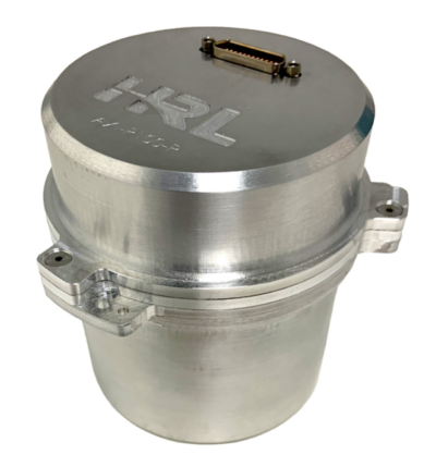
HRL Laboratories has introduced a new inertial measurement unit (IMU) that provides near navigation-grade accuracy in a palm-sized package.
Smaller and lighter than grade-equivalent conventional sensors, HRL’s AXI-R100 delivers range-extending accuracy for GPS-contested navigation. The product is now ready for pre-production orders.
Using silicon microelectro-mechanical systems (MEMS) technology, HRL’s gyros exceeds the performance of many tactical-grade IMUs in the same or smaller package size, and is manufactured in high volumes at wafer-scale. This near navigation-grade performance is available at a tactical-grade price.
The new IMU is suitable for use in defense, aerospace and automotive applications, including missile-guidance systems and drone navigation, as well as for commercial automotive applications with higher levels of autonomy. The product is ready for integration as it has been designed and tested against challenging vibration, shock and thermal conditions representative of those applications.
HRL will present product specifications at the 2026 Joint Navigation Conference, taking place this week in Cincinnati, Ohio, and is exhibiting in booth 129.
By leveraging high volume design automotive methodologies, HRL designed AXI-R100 navigation sensors to scale for high-volume automotive demand while maintaining performance superiority over traditional tactical-grade sensors. The result is a gyroscope compatible with foundry fabrication processes for high volume applications.
“Our gyroscopes and inertial sensors support navigation, pointing and stabilization systems for autonomous vehicles, aircraft and guided missile and munition applications,” said Jeff Dickman, director, Precision Sensing, HRL Laboratories. “We leveraged our extensive microelectronics legacy along with innovations in micromechanical and manufacturing processes to pave the way for AXI-R100 to address the urgent needs from our industrial base.”
Visual localization is widely used as a low-cost solution for autonomous driving, robotics, and mobile navigation. However, monocular systems remain vulnerable to illumination changes, weak texture, occlusion, motion blur and long-term drift.
Existing map-based methods can reduce that drift by aligning camera observations with a prebuilt global map, yet many still struggle with redundant computation, weak cross-modal matching between camera images and point clouds, and optimization errors in large-scale or repetitive scenes.
The challenge is especially important for lightweight platforms that cannot afford onboard lidar, inertial measurement unit (IMU) and heavy computing. Because of these problems, deeper research is needed on camera-only map-based localization that can stay accurate, efficient and stable in complex real-world environments.
Overview of the proposed camera-only map-based localization framework. (Credit: Satellite Navigation)
On April 20, researchers from Wuhan University and Chongqing University reported (DOI: 10.1186/s43020-026-00196-x) in Satellite Navigation a camera-only localization framework that uses prebuilt colored point cloud maps, a dual-sparsity matching strategy that retains high-gradient features in both the map and image observations, and hierarchical geometric–photometric optimization to improve both positioning accuracy and computational efficiency in GNSS-challenged environments.
The system is built around two connected stages. First, the researchers generate a sparse colored point-cloud map from a denser map produced by lidar–IMU–camera mapping, keeping only high-gradient points that preserve visually salient structures while removing weak or redundant information.
They apply a similar sparse selection process to online camera images, creating what the team calls “dual-sparsity matching” between map and observation. During localization, the method uses Lucas–Kanade optical flow to track sparse 2D image features and associates them with 3D map points, while hidden-point removal helps retain only the map points actually visible from the current viewpoint.
The pose is then refined through an iterated error-state Kalman filter in two stages: a geometric PnP-style correction for stable coarse alignment, followed by photometric refinement using image intensity consistency for sub-pixel accuracy.
Tests on the R3live and WHU-Motion datasets showed major gains over existing methods. Compared with direct sparse localization (DSL), the new approach cut absolute trajectory error (ATE) by 52% to 95% across challenging sequences, including a drop from 1.883 m to 0.152 m on R3live_5. It also improved accuracy by up to 76.6% over I2D-Loc++, reduced total processing time by as much as 47.7%, and remained robust in degenerate scenes where geometry-only localization deteriorated to 9.23 m while the proposed tracker held an ATE of 0.076 m.
Ablation results further showed that colored maps, bidirectional sparsity, and hierarchical optimization each played a distinct role in achieving the final balance of speed, robustness, and precision.
The authors said the main advance is not simply adding color to a map, but treating the global colored point cloud map as a continuous observation within the visual odometry framework. They said the framework shows that a monocular camera can localize far more robustly when paired with a prebuilt colored point cloud map and a coarse-to-fine optimization design that avoids poor local solutions.
In their view, the study offers a practical middle ground between fully sensor-rich systems and fragile vision-only pipelines, preserving much of the accuracy benefit of map-based localization without demanding equally heavy hardware on the client platform.
The work could have immediate value for indoor logistics robots, underground inspection platforms, warehouse vehicles, parking-garage navigation systems, and other low-cost autonomous agents operating where GNSS is weak or unavailable. Because the mapping can be completed offline and reused, the online platform needs only a monocular camera, which lowers sensing requirements while retaining strong global constraints.
That makes the method especially attractive for scalable deployments in structured but challenging spaces such as tunnels, campuses, hospitals, and industrial facilities. More broadly, the study suggests that future navigation systems may become both lighter and more dependable by making better use of the information already shared between maps and images, rather than relying only on ever-larger sensor stacks.
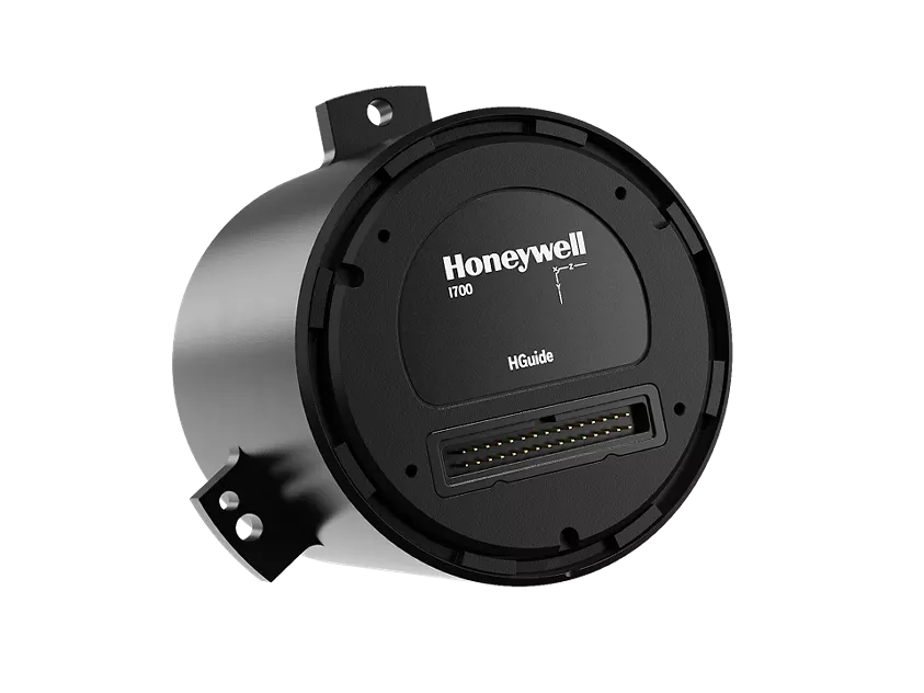
Honeywell has launched the HGuide i700, an inertial measurement unit (IMU) that delivers high-accuracy performance for unmanned air, land and sea vehicles. By pairing near navigation-grade capability with a no-license-required (NLR) classification, the HGuide i700 provides integrators worldwide with a powerful new option for critical sensing and navigation.
The HGuide i700 uses high reliability sensors and electronic architecture found in Honeywell’s HG3900 inertial measurement unit (IMU). Compact and low power, the HGuide i700 delivers near-navigation-grade accuracy and reliability while being optimized to support longer range navigation in GNSS-denied environments
“As customers explore new autonomous, robotic and precision-guided solutions, they want the accuracy and reliability of inertial systems that can be tailored to their program requirements,” said Matt Picchetti, vice president and general manager, Navigation and Sensors, Honeywell Aerospace. “The HGuide i700 offers strong GNSS-denied performance for by limiting maximum acceleration and spin rates in a license-free package that simplifies the complexity of system development while preserving reliability.”
The latest in Honeywell’s HGuide suite of no-license inertial solutions, the HGuide i700 allows customers to streamline development cycles, simplify system architecture and transition to field deployment more quickly than existing technology.
The HGuide i700’s rugged design, compact size and low-power profile make it suitable for diverse commercial, industrial and defense applications, such as:
Unmanned aerial, land or sea vehicles
Mobile mapping and surveying systems
Long duration unmanned ground or surface platforms
Robotics and industrial automation
Stabilized payloads and pointing systems
Honeywell has been a top innovator in IMU technology for more than three decades and pioneered the use of MEMS technologies in navigation. For more information about the Honeywell HGuide i700 and Honeywell’s navigation solutions, visit Honeywell Aerospace.
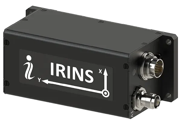
Inertial Labs, a Viavi Solutions Inc. company, has announced IRINS, a low Earth orbit (LEO)-aided inertial navigation system (INS) designed to allow full operation across land, air and sea in GNSS-denied, -degraded and -disrupted space operating environment .
Combining the capabilities of an INS, an altitude and heading reference system (AHRS) and a LEO PNT receiver, this platform marks a major milestone in Viavi’s portfolio for assured positioning, navigation and timing by bringing together the INS capabilities of inertial labs and the timing expertise of Jackson Labs.
The IRINS embedded system has been developed to counter the exponentially rising number of spoofing and jamming attacks that have affected military and critical infrastructure. Now, resilient LEO-based PNT and inertial navigation are available within a fully integrated system from a single vendor.
The system combines an INS, an AHRS and the GNSS-independent STL-2600 LEO Iridium receiver module. These capabilities enable the system to calculate altitude, position, velocity and time data, as well as minimize bias from causing drift. To help detect and eliminate attack signals, the device additionally integrates a GNSS receiver with a controlled reception pattern antenna (CRPA) port.
“The IRINS is the first fruit borne of VIAVI’s visionary strategy to mitigate vulnerabilities in positioning, navigation and timing, bringing together resilient satellite-based timing with tactical-grade IMUs to deliver the most precise PNT for GNSS-denied environments,” said Jamie Marraccini, vice president, Inertial Labs Products, Viavi. “By tightly coupling inertial sensing, LEO-based timing and navigation and anti-jam GNSS technologies into a single platform, the IRINS provides unmatched continuity, accuracy and trust for operations in contested and denied environments.”
“Assured access to PNT is critical for operations in contested environments,” said Maynard Porter, Director, Government PNT Business, Iridium. “Integrating Iridium PNT alongside VIAVI’s INS and AHRS provides users with an exceptionally resilient source of time and location data to maintain operational effectiveness when GNSS signals are disrupted.”
The IRINS is certified for IP67 and MIL-STD-810G environmental requirements. It is based on the company’s fully calibrated tactical-grade MEMS 3-axis accelerometer, gyroscope and clock. These are combined with embedded barometers, magnetometers and an optional onboard air-data computer as part of its AHRS.
Satellite communication is provided through the company’s STL-2600 receiver, which links to the Iridium LEO constellation. All capabilities are housed within a compact 126.5 × 49.3 × 53.3 mm enclosure.
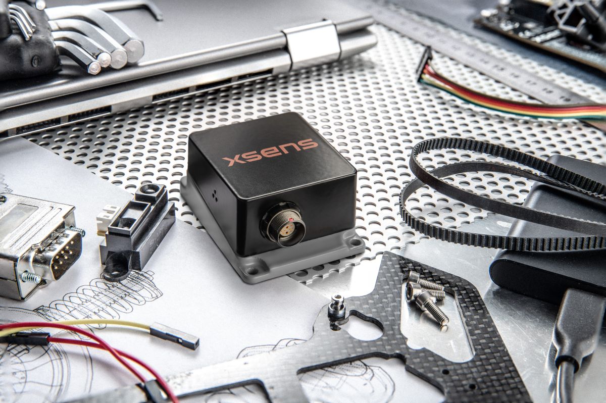
Firmware upgrade available for Xsens Sirius and Xsens Avior motion sensors delivers centimeter-level vertical displacement measurement for marine stabilization and control systems
Xsens has announced a major capability upgrade for its industrial-grade Xsens Sirius and Xsens Avior inertial measurement units (IMUs). The new Heave feature delivers centimeter-level vertical displacement measurement, enabling real-time stabilization and wave compensation in a wide range of marine applications.
Marine engineers can now access comprehensive motion data — roll, pitch, yaw and Heave — from a single compact sensor. This eliminates the need for external processing or for oversized tactical-grade systems while maintaining the precision required for offshore platforms, vessels, docking systems, marine robots, buoys and surveying equipment.
The Heave output operates at up to 100Hz, providing the real-time response needed in active stabilization and wave compensation systems. All processing happens on-device, simplifying system integration and reducing latency.
Xsens motion reference units (MRUs) — IMUs with Heave capability — deliver real-time Heave accuracy better than 5 cm for wave periods up to 29 s. This covers most marine applications. For longer wave periods up to 40 s, accuracy is approximately 6cm, twice the range supported by comparable industrial-grade MRUs.
“Engineers now get vertical displacement data directly onboard, alongside roll, pitch and yaw,” said Ayush Sharma, Algorithms Engineer at Movella. “This gives marine customers the complete motion reference they need for stabilization and compensation systems, without the size or certification overhead of tactical MRUs.”
The algorithm uses proprietary phase correction and bias estimation to mitigate the effect of drift over extended operating periods. Users can also define offset points — center of rotation (COR) and point of interest (POI) — ensuring that Heave values reflect the true motion of the vessel or payload, even when the MRU is installed away from the POI.
The Heave algorithm is available for download immediately as a firmware update for existing Xsens Sirius and Xsens Avior units in the field, with no hardware modifications required. All new units ship with the feature integrated. Heave output is enabled with a single setting in the MT Manager software or the Xsens software development kit (SDK).
Designed for straightforward integration
Xsens Avior is a compact OEM module for embedded system designs.
Xsens Sirius is a standalone MRU in a rugged IP68 housing for harsh environments. It meets MIL-STD-202 requirements.
Both products support RS-422, CAN, and UART interfaces. Development kits are available for prototyping, with free SDKs for C/C++, Python, ROS1, ROS2, and MATLAB. All units meet CE, FCC, and RoHS regulatory requirements, and are ITAR-free.
Xsens Avior and Xsens Sirius MRUs are available globally from Movella and authorized partners. For specifications, datasheets, and ordering information, visit www.movella.com/products/sensor-modules or contact a Movella sales representative.
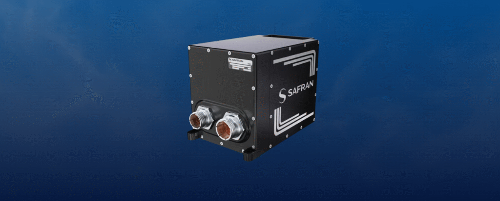
Skynaute is a hybrid inertial/GNSS navigation system based on HRG Crystal technology. It will serve as a critical component of the Hercules avionics suite designed and integrated by Moog.
The Skynaute navigation unit by Safran. (Photo: Safran Federal Systems)
Under this agreement, Safran Federal Systems will supply Skynaute units to support enhanced navigation performance in demanding operational environments.
“Being selected by Moog underscores the reliability, innovation, and mission readiness of our Skynaute solution,” said Tony Full, senior director of Business Development, Navigation Systems, Safran Federal Systems. “This collaboration continues our tradition of delivering precise, resilient navigation technologies to meet the evolving needs of military aviation.”
Skynaute is engineered to meet the needs of both legacy and next-generation military aircraft, providing superior accuracy and robustness with minimal size, weight, and power consumption. The system is suited for retrofit and modernization programs, particularly for platforms like the Hercules that remain integral to global air mobility and tactical transport operations.
Safran Federal Systems supports Safran Defense & Space Inc. (Safran DSI) by providing APNT technologies across a range of defense and aerospace applications.
The IMU-FI-200C FOG IMUs are a fully integrated inertial measurement solution that combines the latest closed-loop FOG and MEMS sensors technologies
Inertial Labs has released the IMU-FI-200C high-performance fiber-optic gyroscope (FOG) inertial measurement unit (IMU), a compact, self-contained strapdown, advanced tactical-grade IMU that measures linear accelerations and angular rates with three-axis tactical-grade, closed-loop FOG and three-axis high-precision MEMS accelerometers in motionless and high-dynamic applications.
The IMU-FI-200C FOG IMUs are a fully integrated inertial measurement solution that combines the latest closed-loop FOG and MEMS sensors technologies. It is designed for a wide range of higher order integrated system applications, such as
antenna and line-of-sight stabilization systems
passenger train acceleration/deceleration and jerking systems
motion reference units
motion control sensors
gimbals
electro optical components/infrared
platform orientation and stabilization.
Fully calibrated, temperature-compensated and mathematically aligned to an orthogonal coordinate system, the IMU contains gyroscopes with an accuracy of up to 0.5 deg/hr and accelerometers with a bias repeatability of less than 2-mg over their operational range, very low noise and high reliability.
The IMU-FI-200C FOG IMUs have been thoroughly tested to perform in significant variations in temperature, high vibration and shock, and is designed to be used in air, marine and land environments.
“New technology creates new opportunities, and the new IMU-FI-200C represents the innovative approach we take every day at Inertial Labs,” said Jamie Marraccini, president & CEO of Inertial Labs. “The high performance and flexibility to integrate into different systems and applications is what we have striven to provide to our customers with this new release.”
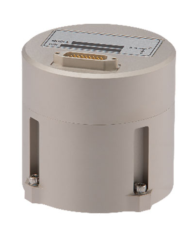
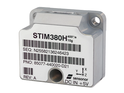
Safran Electronics & Defense is taking a major step forward in its inertial navigation strategy by grouping two subsidiaries, Safran Colibrys (Switzerland) and the recently acquired Sensonor (Norway,) under a single banner, Safran Sensing Technologies.
The similarities in expertise, market position, customers and technologies result in clear synergy between these two companies, which produce accelerometers, gyrometers and inertial measurement units (IMUs). The creation of Safran Sensing Technologies shows Safran’s commitment to developing its micro-sensor business through these two companies.
The STIM380H inertial measurement unit. (Photo: Sensonor)
The goal is to jointly offer a wider and comprehensive range of inertial technologies including vibrating sensors, optics and micro-electromechanical system (MEMS) for applications in aeronautics, defense, space and other industries.
The two subsidiaries have already delivered more than 20 million MEMS sensors to the aeronautics, defense, space, transport, mobility and industry sectors. For example, MEMS are used in the control accelerometers of automobile airbags, in high temperature accelerometers for guiding drill heads, and in seismic sensors measuring the structural health of buildings or civil engineering works. They are also used in IMUs for civil, military and space vehicles.
This change is part of a broader Safran Electronics & Defense strategy designed to strengthen the company’s position in the positioning, navigation and timing (PNT) market.
The two entities have been renamed Safran Sensing Technologies Norway AS and Safran Sensing Technologies Switzerland SA, respectively.
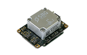
SBG Systems has announced a new inertial navigation system (INS) named Quanta Micro, completing its Quanta product line.
The Quanta Micro GNSS-aided INS offers a unique combination of navigation performance and low size, weight, power and cost (SWAP-C).
Quanta Micro leverages a survey-grade inertial measurement unit (IMU) for optimal heading performance in single antenna applications, and high immunity to vibrating environments. An optional secondary antenna enables fast heading initialization in low dynamic applications.
Main Features
Accuracy: 0.015° roll/pitch, 0.035° heading, 1 cm position (PPK)
Integrates a survey-grade IMU: 0.8°/h gyro bias instability
Versatile INS/GNSS to suit land, air or marine applications
Highly tested and calibrated from -40°C to 85°C
Robust to vibrating environments
Quad-constellation multi-band RTK GNSS receiver
Smooth post-processing workflow with Qinertia software
Major size reduction with no compromise on performance.
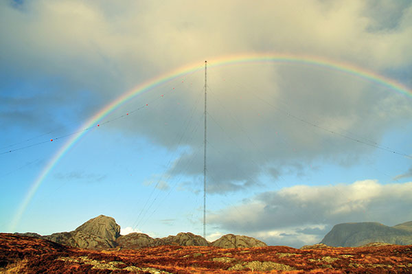
the former Loran-C transmission antenna at Værlandet, Norway. (Photo: UrsaNav)
By Alan Grant and Dana Goward
In my “First Fix” editorial in the January 2022 issue of this magazine, I listed 10 questions about eLoran I had received from a PNT expert in response to an article about eLoran I wrote for the November 2022 issue. I encouraged eLoran proponents to address these questions. Two well-known authorities, neither of whom have a financial interest in the technology, stepped forward to help. Below, again, are my 10 questions about eLoran and their answers.
Alan Grant is head of Research and Development for the General Lighthouse Authorities of the United Kingdom and Ireland (GLA). He is an expert in radionavigation systems and leads the team that established the U.K.’s eLoran system, which operated from 2007 to December 31, 2015 in support of maritime users.
Dana A. Goward is president of the Resilient Navigation and Timing Foundation and a retired U.S. Coast Guard Captain. He also served in the federal Senior Executive Service as the maritime navigation authority for the United States. He has decades of experience with navigation policy and leading government policy and programs.
— Matteo Luccio, Editor-in-Chief
Accuracy specifics. While my November article stated that eLoran would have a two-dimensional accuracy of “better than 20 meters, and in many cases, better than 10 meters,” is that RMS, 95%, or some other statistic?
AG: Like any radionavigation system, the achievable accuracy will depend on several aspects, including the user’s location with respect to the broadcast stations and how error sources are modelled. The GLA eLoran service, when in operation in 2015, provided positional accuracy in the order of 8-10m (95%) to seven ports on the east coast of the UK. These ports had local reference stations to help manage temporal errors and the ports had been mapped to correct for additional secondary factors (ASF).i
DG: Others have reported greater accuracies using differential corrections.
Performance standard. GPS provides a commitment to users in a published performance standard. What specific measures of positioning accuracy, integrity and continuity would you recommend the proposed eLoran system be committed to provide (using the architecture described in the answer to Question 6)?
AG: The target performance would need to be tied to the target use cases to ensure the appropriate requirements are met. IALA provides guidance in this area for maritime services with general maritime requirements provided by the IMO within resolutions A.1046 and A.915.
Coverage. Would you recommend this eLoran positioning performance hold for the entire United States (including Alaska, Hawaii, Puerto Rico and other territories), only for the “lower 48” states, or only parts of these 48 states?
DG: The primary goal of any effort to complement and back up GPS/GNSS would be to make the nation and its citizens safer in at least two ways. First, to provide an alternative PNT source or sources in the event that signals from space were not available for any reason. Second to make GPS satellites and signals (and therefore the nation) safer by “taking the bullseye off GPS.” Having one or more alternatives will greatly reduce incentives for malicious disruption. To achieve these two goals the alternatives must be widely available and easily accessed. How widely available and easily accessed the United States or any other country wants to make such systems is a policy decision.
Current users. By number of users, the predominant common current civil uses of GNSS for positioning are consumer devices (mostly cellphones). By contribution to the U.S. economy, the predominant uses are high-precision applications. For what fraction of these uses would eLoran positioning be adequate? Could an eLoran receiver and antenna fit in today’s consumer devices?
DG: Lots of presumptions and assumptions in this question. Several overall thoughts, though. First, determining users’ real requirements can sometimes be difficult. I have a nice new full-size sedan. So, I think that is my requirement even though I could get to work almost as quickly and much less expensively if I owned a used compact car or caught the bus at the corner.
Second, GPS/GNSS will, hopefully, always be the primary source. The questions then are 1) how accurate can eLoran positioning become with additional work, and 2) how accurate does a fallback system need to be?
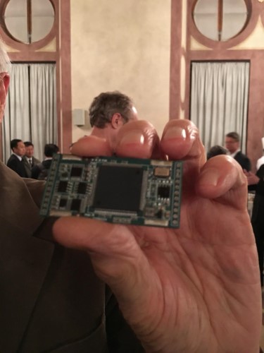
Durk van Willigen of Reelelektronika b.v. displays a combined GPS, GLONASS and eLoran receiver at the 2017 Munich Satellite Navigation Summit. (Photo: Reelelektronika)
Finally, as to equipment size, I recall seeing a photo of the first GPS receiver sitting on a pallet with two chairs for operators. Today, receivers are made at chip scale. Huge reductions in C-SWAP have been the growth arc for all kinds of technologies as they are implemented more and more widely.
In 2017 the Dutch company Reelektronika showcased a combination eLoran, Chayka, GNSS receiver that was only 6 cm long. This was achieved without a whole lot of investment in research and development. Who knows how low C-SWAP for eLoran receivers will go?
Future uses. Emerging civil uses of GPS for positioning include autonomous ground and air vehicles, navigation to space and in space, and lane-accurate car navigation. Which of these could be served by eLoran?
AG: The overall concept of having a mix of dissimilar position sources remains sensible for all modes. GNSS is expected to remain the primary means of position determination, with different use cases selecting different complementary systems based on their needs. eLoran may support some use cases but may not be the answer for all.
DG: Many believe GPS alone is not sufficient to serve some of the applications cited. This is the basis for language in both the European Radionavigation Plan and a U.S. Presidential Executive Order cautioning against over-reliance on GNSS. Perhaps GPS and eLoran together might be deemed sufficient. Or, perhaps a more diverse and resilient PNT architecture will give rise to additional applications such as precise positioning from 5G that will be sufficient.
Architecture. To maintain accuracy during a prolonged GPS outage, eLoran would require reference stations to calibrate time-varying propagation errors, as well as a certain number of transmitters for good nationwide geometry and for redundancy, ensuring service even if a transmitter is attacked or is taken off-line for maintenance. What architecture would you recommend to achieve this?
AG: The MarRINav projectconsidered a similar question for the UK and the project’s approach could be employed to consider this question for the United States.iv
DG: A good starting point for the United States might be the sites used by the shuttered Loran-C system. The federal government still retains custody of most of them. Also, considerable thought has been given to the questions of eLoran reference stations and integrity in the United States. PNT expert Mitch Narins, formerly of the FAA and now Strategic Synergies, advises that much of this work has been done. The FAA and Coast Guard conducted a study to deploy eLoran in the United States to support aviation non-precision approach, maritime harbor entrance and approach, and precise time and frequency users. The proposed architecture supported aviation’s demanding integrity requirement (1×10⁻⁷), maritime’s demanding accuracy requirement (8-20m), and time and frequency users’ precision requirements (100 ns/Stratum 1).
7. Infrastructure cost. What would be the cost of installing the required transmitters, power supplies, reference stations, communication links and control system for the architecture described in the answer to Question 6? Can you reference a recent and independent estimate? To a ballpark figure, what cost fixed-price contract would you accept to implement it? Similarly, what would be the annual costs for operating and maintaining this infrastructure?
AG: The MarRINav project produced a cost-benefit analysis report that addresses some of these questions, albeit aligned to the approach proposed for the UK. The documents are open source and available on the MarRINav website.
DG: To quote President Kennedy, “There are costs and risks to a program of action, but they are far less than the long-range risks and costs of comfortable inaction.”I agree with Dr. Grant that the capital costs in MarRINav are roughly transferrable to the United States. As another data point, the 2010 operating cost for Loran-C in the United States was about $36M/year. That number included several hundred employees, though. Plans to automate the system projected reducing annual costs to $15M/year in 2010 dollars.
Impact. eLoran transmitters are large and high-power. Providing positioning across the United States could require building some of them from scratch or significantly reconstructing old Loran sites. What issues — such as environmental, aviation safety and security — would this raise, and how would you recommend they be addressed?
DG: These issues would be dealt with the same way they are for any construction project. eLoran transmission sites are essentially the same as commercial AM radio stations. Reusing sites still owned by the government could make the process even easier. Compared to the cost and difficulty of putting PNT assets in orbit, these challenges should be relatively easy to overcome.
Receivers. Assuming all the above were achieved, it would accomplish nothing unless eLoran receivers were widely purchased, installed and used. How much would that cost? Who would pay? Should we assume that “if we build it, they will come”?
AG: This is a valid concern and has different answers depending on the planned use case and the level of national/international standardization required. Within the maritime sector, the IMO has approved a multi-system receiver performance standard that supports the use of all GNSS and terrestrial systems within one device, rather than having a separate eLoran receiver.
DG: I completely agree — adoption and use are absolutely key. Fortunately, government leaders have a wide variety of levers to influence adoption and use. These range from education and encouragement to regulation, legislation, and subsidies.
Alternatives. Given the widespread development of other positioning technologies over the past decade, much has changed since the earlier recommendations for eLoran. How do we know that eLoran is the right investment — or even a needed part of the solution or needed system in a system of systems — for the future of U.S. PNT?
AG: The MarRINav project researched and compiled details of different positioning, navigation and timing technologies supporting maritime navigation, within Deliverable D4. The recommended system-of-systems approach recognized that there was no one-fit-all solution, rather it sought to allow for a scalable solution that reflects users moving from location to location and between systems. It considered global, regional and local solutions, recognizing the cost vs. usable coverage tradeoff for each. The proposed solution of GNSS, supported by eLoran in combination with VDES R-Mode and radar absolute positioning, was deemed as the most appropriate mix for the UK, given geographical and political constraints. The approach can be ported to investigate the appropriate options for the United States.
DG: The U.S. Department of Transportation’s January 2021 report to Congress has findings similar to those in MarRINav. It described a system of systems that included fiber, satellites and terrestrial broadcast. The department subsequently said that a critical factor for a terrestrial broadcast system would be the coverage area per unit of required infrastructure. Of the systems discussed, eLoran met this criterion best. This recent finding is consistent with numerous other government reports, two previous government announcements that it would build eLoran, two recommendations from the President’s National Space-based Positioning, Navigation, and Timing Advisory Board and the technology’s on-going use around the world. Likely someday there will be something to replace GPS and other legacy technologies. We must work with the combination of technologies we have now until that day arrives.
Common Threats
Common threats to GNSS and eLoran could include the following:
1. Cyber attacks. Given that GPS’s OCX is said to be the most cybersecure system built by the U.S. Department of Defense, how would eLoran’s control system be even more cybersecure than OCX, to avoid a common cyber-vulnerability?
AG: Cybersecurity is a key concern and one that any navigation and safety of life system must consider. I will leave manufacturers of each system to comment on how secure they are. However, if we consider signal interference and data manipulation within this category, then using a stronger signal at a different frequency to GNSS provides some protection against jamming. While any radio signal can be jammed, the perpetrator would need more power and physically larger equipment to jam at lower frequencies.
DG: Yes, the security of control systems is very important and must be included in the design up front. Authentication and security of signals, and the cybersecurity of receivers must be as well. This is especially true for complementary systems for GPS since GPS signals are so open and vulnerable, and so many receivers are largely unprotected. We will have the opportunity to do better with a new system and avoid the huge expenses of OCX, the new GPS control system.
Additionally, let us not forget that cybersecurity is needed for much more than control systems. Signals and receivers need to be much more secure than civil GPS is right now. A new system, be it eLoran or another technology, will be able to build cybersecurity in from the beginning.
Physical attacks. Given concerns about possible physical attacks on GPS satellites, which move at multiple km/sec 20,000 km from Earth, would it not be easier to physically attack eLoran transmitters, which are stationary, terrestrial, in remote locations, and hundreds of feet tall and require massive power sources?
AG: We should not lose sight that any ground infrastructure can be attacked, regardless of whether it is a satellite uplink station or part of a terrestrial communications or positioning system. Careful selection of the transmitter location, along with suitable site security options should help deter the attack and mitigate the impact where possible.
DG: Every physical asset and every signal is vulnerable to some degree to attack by a host of malicious actors, and damage by a variety of natural occurrences. The key to resilience and making PNT sources less attractive targets is to have diverse sources with the smallest number of common failure modes.
Space weather. GPS is potentially vulnerable to severe space weather that could damage satellites or temporarily hinder signal propagation from space to Earth. However, severe space weather could also damage the power grid upon which megawatt eLoran transmitters rely. How would eLoran service be protected from the effects of severe space weather, such as a Carrington Event?
AG: Space weather has the potential to affect all radio broadcasts. Depending on the type of event it can affect performance several different ways, including ionospheric scintillation, applying forces to satellites or disrupting power networks. The aim is to use systems where the underlying failure modes are as different as possible. Using a combination of satellite and terrestrial signals, at different frequencies, with local power generation where possible can help mitigate the impact. Whether it’s possible to mitigate all the implications of a Carrington type event is not clear and perhaps one for the experts.
DG: With the available warnings about solar events, it is conceivable that both GNSS and terrestrial systems could be powered off or otherwise secured for such an event to minimize damage. A new-build terrestrial system could also be constructed with surviving a Carrington Event in mind. And, of course, terrestrial systems will be easier to access, repair, and replace than those in space. As for other possible issues with the power grid, generators, uninterruptable power supplies, and other backup methods can easily be installed. Before 2010, several U.S. Loran-C transmitters were in such remote locations, they never had grid power and were always powered by generators.
Spirent Federal Systems, a provider of PNT/GNSS test equipment, announced plans to fully validate the inertial interface between Spirent GNSS simulators and both Northrop Grumman legacy and modernized inertial systems under the EGI‐M program.
For years, Spirent Federal has developed inertial interface test tools in collaboration with Northrop Grumman that yield repeatable, accurate results.
Northrop Grumman’s embedded GPS/inertial navigation system (INS)‐modernization, or EGI‐M, program is developing airborne navigation capabilities with a government‐owned open architecture. The fully modernized system integrates new M‐code capable GPS receivers, provides interoperability with civil controlled air space, and implements a new resilient time capability.
“Spirent Federal has long supported testing of the Northrop Grumman family of interfaces,” said Jeff Martin, Vice President of Sales for Spirent Federal, “and our customers have always obtained precise, reliable results. Spirent Federal strives to keep abreast of the newest technology to be ready to meet the needs of industry, and this collaborative effort that includes the EGI‐M program is yet another example. Spirent is an important part of Northrop Grumman’s test solutions and this validation project acknowledges that importance.”
Spirent Federal has been providing tools for testing inertial systems for more than two decades. Available SimINERTIAL interfaces comprise various EGIs and IMUs from manufacturers of inertial sensors, including Northrop Grumman (formerly Litton), Honeywell and Atlantic Inertial Systems, as well as standardized interfaces such as STANAG.
Testing the full operational performance of GPS/inertial systems usually requires expensive and time‐consuming field testing on a moving vehicle. Spirent’s SimINERTIAL system emulates inertial sensor outputs while concurrently simulating GPS RF signals, enabling controlled, repeatable testing of EGIs and reducing the need for field trials.
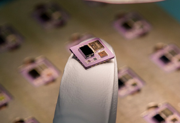
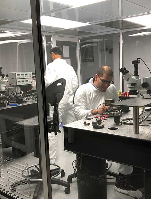
KVH photonics engineers test PICs for validation prior to production. (Photo: KVH)
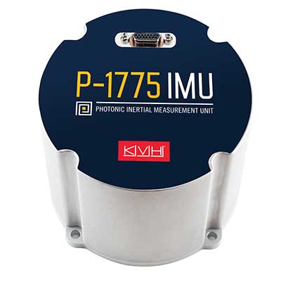
In June, KVH Industries launched the P-1775 inertial measurement unit (IMU), featuring its new PIC Inside photonic integrated chip (PIC) technology.
After developing and testing the technology for more than three years, the company began incorporating it into existing product lines and has shipped the first units.
The PIC technology features an integrated planar optical chip that replaces individual fiber-optic components to simplify production while maintaining or improving accuracy and performance.
The product is designed to deliver 20 times higher accuracy than less expensive micro-electromechanical systems (MEMS) IMUs. It uses modular designs for ease of integration and has outstanding repeatability unit-to-unit, according to the company.
KVH will add the technology to its inertial sensor product line for use across a broad range of applications, from navigation to stabilization and pointing.
KVH’s fiber-optic gyros (FOGs) and FOG-based products are particularly well-suited for the large and growing autonomous market, which includes applications on land, sea and air, such as drones, people movers, trucks and mining and construction equipment.
Moving Components to the Chip
Photo:With PIC technology, KVH’s FOG production process incorporates machine automation for photonics assembly. (Photo: KVH)
The controls on FOGs have an electronics portion and an optics portion. The latter consists of a light source, a detector, couplers, polarizers, a coil (which performs the sensing), and a piezoelectric device for modulating the light, explained Robert Balog, KVH’s chief technology officer.
Until now, the company had fabricated all the products for that optical circuit in its Chicago facility, in a process that was labor-intensive and required much process control. For the PIC, “We’ve taken the couplers and the polarizer sections specifically and moved them onto the chip level,” Balog said.
While KVH manufactures the chip much like any other semiconductor device, rather than passing the light through the fiber KVH is now passing it through wave guides that are contained within that photonics chip, thereby moving the creation of the coupler module into a wafer-level component.
Mass Production and Better Quality
KVH produces the chips en masse on a wafer, then singulates and samples them. Once they are qualified and spot-checked, the chips are incorporated into KVH products.
“This affords us a way to mass produce those components,” Balog said, “and gives us much better quality.”
Photo: KVH
Additionally, it produces a much smaller device than before. The company will not reveal any numbers regarding its performance improvement until it produces and distributes more PICs, but “it is already producing better results than the manually produced components.”
The production process is intimately linked to the overall performance of the sensor. “The tighter your process control, the more reliable you can make the product,” Balog said.
The new process also improves the device’s field reliability because it contains fewer discreet components. The improved performance specifications on each individual FOG improve the overall performance of the IMU or the inertial navigation system (INS) because the bias is more stable and repeatable.
The Future
What is in the technology’s future?
“The next step is integrating the light source and the detector and potentially a modulator into that chip as well,” Balog said. “So, our ultimate technology road map is to continue condensing what would have been discrete components in traditional gyros all within that chip. As this technology progresses, it will get smaller, tighter, and better. Then you will see big leaps in performance.”