New patented PIC Inside technology is designed to enhance inertial sensor performance and reliability for the growing autonomous market
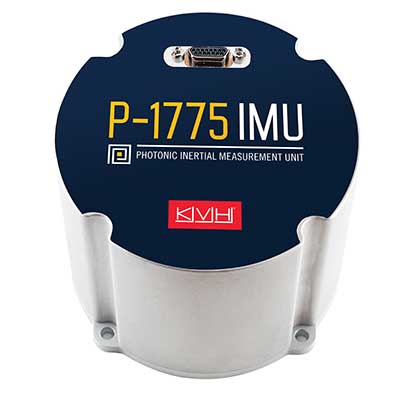
Photo: KVH
KVH Industries has launched the P-1775 inertial measurement unit (IMU), featuring KVH’s new PIC Inside photonic integrated chip (PIC) technology.
KVH has been developing and testing the technology for more than three years and is now incorporating it into existing product lines. The first units have started shipping.
One of the first customers has integrated the P-1775 IMU into its next-generation rocket launch vehicle.
KVH’s PIC Inside technology features an integrated planar optical chip that replaces individual fiber-optic components to simplify production while maintaining or improving accuracy and performance.
The PIC Inside product is designed to deliver 20 times higher accuracy than less expensive MEMS inertial measurement units, uses modular designs for ease of integration, and has outstanding repeatability unit-to-unit.
“I applaud the tremendous effort by our incredible engineers in developing this groundbreaking technology and I am thrilled that we have begun to incorporate PIC Inside technology into our existing products, a process that we expect to continue throughout the year,” said Martin Kits van Heyningen, KVH CEO.
The PIC technology will be added to KVH’s inertial sensor product line for use across a broad range of applications from navigation to stabilization and pointing. KVH’s fiber-optic gyros (FOGs) and FOG-based products are particularly well-suited for the large and growing autonomous market. This market includes applications on land, sea and air, such as drones, people movers, trucks, and mining and construction equipment.
Autonomous applications rely on high-quality inertial sensors to deliver an extremely accurate navigation solution, delivering the performance required in critical metrics such as angle random walk (ARW) and bias instability.
Next-generation driverless cars, which require centimeter-level precision for safety, are the ideal application for KVH’s inertial products, KVH said. Employing the PIC design allows for a lower cost and scalable solution due to the elimination of various fiber components and a reduction of labor.
In 2019, KVH delivered its first product prototypes containing PIC technology to automotive customers and presented the science behind the technology to an audience of engineers at an inertial sensor conference, describing the extensive development, testing, and benefits of the new technology.
KVH is a leading innovator for assured navigation and autonomous accuracy using high-performance sensors and integrated inertial systems. KVH’s widely fielded TACNAV systems are in use by the U.S. Army and Marine Corps as well as many allied militaries around the world. KVH’s FOGs and FOG-based IMUs are in use today in a wide variety of applications ranging from optical, antenna and sensor stabilization systems to mobile mapping solutions and autonomous platforms and cars.
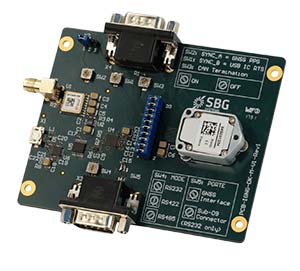
The Horizon fiberoptic gyro (FOG) inertial measurement unit (IMU) now forms part of SBG Systems’ Navsight Marine Solution, dedicated to hydrographers. Navsight is available at different levels of accuracy to meet the various application requirements and can be connected to various external equipment such as echo-sounders, lidar, and so on.
Photo: SBG Systems
Navsight Marine Solution already offered two levels of performance with the Ekinox and Apogee IMUs. These MEMS-based IMUs address most of hydrographics markets whether shallow or deep water.
The new Horizon IMU enables customers to deploy Navsight in the most demanding environments such as surveying highly dense areas (bridges, buildings, and so on) as well as applications where only a single antenna can be used.
The Horizon IMU is based on a closed-loop FOG technology which enables ultra-low bias and noise levels. This technology allows robust and consistent performance even in low dynamics survey.
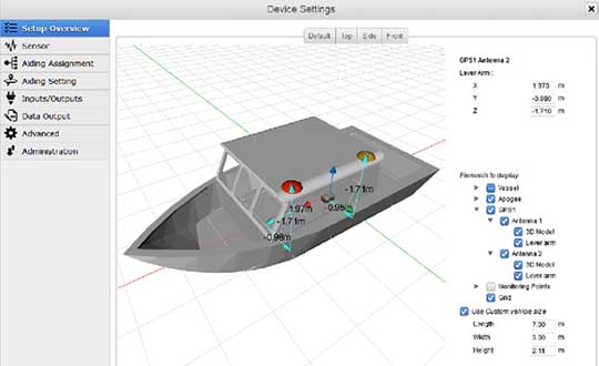
Navsight solution is easy to install, as the sensor alignment and lever arms are automatically estimated and validated. Once connected to the Navsight processing unit, the web interface guides the user to configure the solution. A 3D view of the vessel shows the entered parameters so that the user can check the installation. The Navsight unit also integrates light emitting diode (LED) indicators for satellite availability, RTK corrections, and power. It comes with a rugged enclosure, or in a rack version for larger vessels.
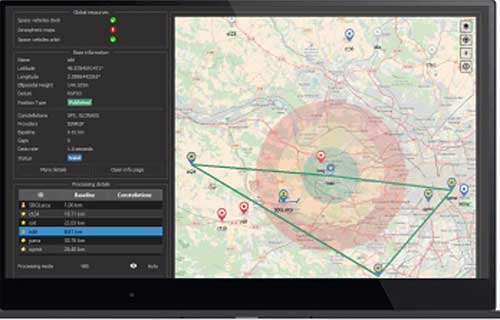
Completing the Navsight offer, Qinertia, SBG’s post-processing software, gives access to offline RTK corrections from more than 7,000 base stations located in 164 countries. Trajectory and orientation are then greatly improved by processing inertial data and raw GNSS observables in forward and backward directions. Computation takes less than 3 minutes for a 6-hour log thanks to the Forward and Backward calculation processed at the same time.
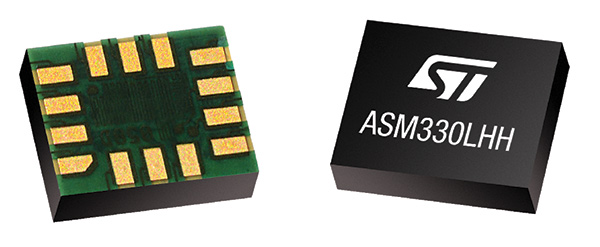
STMicroelectronics has introduced the automotive-grade ASM330LHH six-axis inertial sensor for super-high-resolution motion tracking in advanced vehicle navigation and telematics applications.
Photo: STMicroelectronics
Serving demands for continuous, accurate vehicle location to support automated services, the ASM330LHH lets advanced dead-reckoning algorithms calculate precise position from sensor data if satellite signals are blocked, such as in urban canyons, tunnels, covered roadways, parking garages or dense forests.
Its advanced, low-noise, temperature-stable design enables dependable telematics services such as e-tolling, tele-diagnostics and e-Call assistance. Precision inertial data in six axes also meets the needs of advanced automated-driving systems, the company said.
Automotive component manufacturer Magneti Marelli has selected the ASM330LHH for advanced telematics systems, to be fitted as original equipment by global automotive groups in upcoming vehicle ranges.
For the ASM330LHH, as with all its MEMS sensors, STMicroelectronics owns the entire manufacturing process, from designing the sensors, through wafer fabrication, packaging, test, calibration and supply. Full end-to-end control enables STMicroelectronics to create high-performing sensors and assure customers of a robust and responsive supply chain, with rigorous end-of-line quality screening, the company said.
“STMicroelectronics is the largest supplier of MEMS sensors for automotive non-safety applications, such as navigation and telematics,” said Andrea Onetti, Analog, MEMS and Sensors Group vice president at STMicroelectronics. “Our latest-generation inertial sensor, the automotive-grade ASM330LHH, enables precise positioning for safer, smarter driving.”
Engineering samples will be available for evaluation by the third quarter of 2018, and volume production will begin the following quarter.
Further technical information on the ASM330LHH
Temperature range up 105 degrees Celsius giving designers extra freedom to locate electronic controls in hot areas such as in smart antennas on the vehicle roof, or near the engine compartment.
Ultra low noise allows greater measurement resolution by minimizing integration errors when positioning is reliant on sensors only.
High linearity and built-in temperature compensation eliminate any need for external compensation algorithms over its operating range.
Lowest power consumption in class, with features for optimizing power management if battery usage becomes crucial.
Qualified according to AEC-Q100 automotive-grade robustness standard.
Built on STMicroelectronics’ proven, proprietary ThELMA MEMS process technology, which enables integration of both the three-axis accelerometer and three-axis angular-rate sensor (gyroscope) on the same silicon for optimum yield, quality, and reliability.
The electronic interface integrates the signal chain for both sensors on a single die using STMicroelectronics’ 130nm HCMOS9A technology.
Reference designs, as well as STMicroelectronics’ Teseo satellite-positioning modules and related software are available. The dead-reckoning algorithm included with the Teseo III GNSS-receiver chipset already supports the ASM330LHH to generate a high-accuracy output suitable for autonomous navigation.
Tiny, low-profile 3mm x 2.5mm x 0.83mm device for minimal impact on the size of any on-board module.
Packaged as a leadless Land Grid Array (LGA) device.
NovAtel has introduced several new precision positioning solutions for space-constrained applications. With enhanced positioning accuracy in a compact form, the PwrPak7D, PwrPak7DE1 and OEM7600 are suitable for automotive, airborne and other smaller unmanned systems.
PwrPak7D and PwrPak7D-E1 are dual-antenna, multi-frequency enclosures, and the OEM7600 receiver board, plus NovAtel’s new Waypoint Inertial Explorer Express post-processing software are being showcased this week at AUVSI Xponential 2018.
Dual-Antenna, Multi-Frequency Enclosures
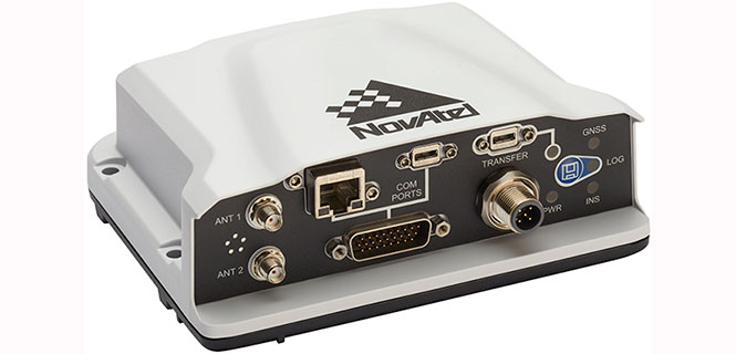
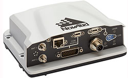
The new PwrPak7D enclosure. (Photo: NovAtel)
NovAtel’s new PwrPak7D and PwrPak7D-E1 enclosures provide space efficiency without sacrificing position accuracy and heading stability, even in stationary, slow-moving or hovering dynamics.
The PwrPak7D-E1 enclosure integrates an inertial measurement unit (IMU) with NovAtel’s OEM7720 dual-antenna receiver board to deliver GNSS and inertial navigation system (INS) capabilities.
When combined with NovAtel’s SPAN technology, positioning and attitude performance is optimized during extended GNSS outages.
Both the PwrPak7D and PwrPak7D-E1 include NovAtel’s Interference Toolkit with advanced interference detection
and mitigation features applicable to all stages of integration. A web user interface, accessible through Ethernet or
Wi-Fi, allows for quick and easy system configuration and control.
OEM7600 Receiver Board for Smaller Autonomous Systems
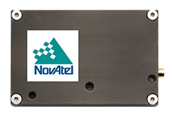
The OEM7600 receiver board. (Photo: NovAtel)
The OEM7600 receiver board features NovAtel’s high-performance positioning solutions in an extremely small form factor, wrapped with protective shielding to isolate emissions from surrounding electronics in confined spaces.
This new receiver integrates easily with NovAtel’s SPAN technology to optimize performance during extended GNSS outages.
The new OEM7600 will be commercially available this summer.
New Post-Processing Software for UAVs and Small Project Areas
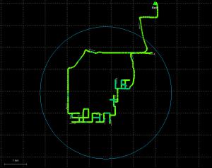
Inertial Explorer Xpress centroid circle. (Image: NovAtel)
Inertial Explorer Express provides the same core processing and utilities as the
Waypoint Inertial Explorer software for applications including unmanned aerial vehicles (UAVs) and smaller projects.
Inertial Explorer Express will produce centimeter-level position and attitude solutions compatible for lidar, camera and other sensor data with faster processing times and reduced complexity
“We are very excited to be introducing our new OEM7-based and Inertial Explorer solutions at Xponential 2018,” said Neil Gerein, director of product management at NovAtel. “These systems provide robust positioning and accuracy in a compact footprint for UAVs and smaller autonomous projects. An advanced range of software options, including NovAtel’s tightly coupled GNSS+Inertial SPAN technology and Interference Toolkit, provide assured positioning anywhere.”
SBG Systems has released the Ellipse 2 Micro series, a new product range designed to reduce the size and cost of high-performance inertial sensors for volume projects. The Ellipse 2 Micro series is available as an inertial measurement unit (IMU), or as an attitude and heading reference system (AHRS) or inertial navigation system (INS) running an extended Kalman filter.
The new Ellipse 2 Micro is available as an IMU for calibrated sensor data, or as an AHRS/INS delivering accurate orientation and navigation using an external GNSS receiver.
The Ellipse 2 Micro series provides excellent navigation data when connected to an external GNSS receiver. The INS fuses in real-time inertial and GNSS information to maintain the vehicle position in air, marine or land applications. For automotive projects, the inertial sensor comes with CAN protocol and connects to the odometer for higher performance in harsh environments, such as tunnels and urban canyons.
“With the Ellipse 2 Micro, integrators benefit from SBG Systems high expertise in motion sensing and positioning in the smallest package,” said Alexis Guinamard, CTO of SBG Systems.
The high-quality micro IMU is calibrated from -40 degrees to 85 degrees Celsius. Combining state-of-the-art MEMS-based gyroscopes, accelerometers and magnetometers, the new Ellipse 2 Micro series is fully calibrated in temperature to eliminate measurement errors such as sensor bias, gain, linearity, alignment and g-sensitivity to provide a constant behavior in all conditions.
Weighing 10 grams, the Ellipse 2 Micros provide a 0.1 degree accurate attitude and connects to external GNSS for navigation, offering a remarkable weight/performance ratio to integrators.
All Ellipse 2 Micro models are now available for order. Product and pricing information is available from SBG Systems representatives and authorized dealers.
Trimble has introduced a new family of Trimble BD GNSS boards for high-precision guidance and control applications.
The BD boards’ simple connectivity and configuration allow system integrators and OEMs to easily add GNSS positioning and orientation — with the ability to upgrade its capabilities — using the same board footprint, connectors and software interface for specialized and custom hardware solutions, the company said.
The compact Trimble BD boards include a broad range of receiver capabilities, from high-accuracy GNSS only to full GNSS-Inertial features for positioning and 3D orientation. Firmware options are upgradeable, allowing functionality to be added as requirements change.
Product manufacturers in markets such as unmanned aerial vehicles (UAVs), autonomous vehicles, fleet management and aviation now have the ability to offer customers an extensive range of capabilities to meet all their needs.
According to Trimble, the low-power BD family of boards includes the BD940 GNSS and GNSS-Inertial boards and new top-of-the-line BD990 GNSS, GNSS-Heading and GNSS-Inertial boards, enabling customers to choose the most appropriate receiver for their applications.
In addition, the BX940 and BX992 are available in a rugged enclosure for applications used in harsh environments.
Integrating Trimble RTX technology, which enables precise and robust location worldwide without the use of a base station, the BD boards are ideal for flexible positioning. Trimble RTX technology enables users to subscribe to a complete portfolio of real-time correction services that deliver varying levels of accuracy depending on the user’s application requirements.
The new BD family incorporates the latest Trimble Maxwell technology with advances in high-precision GNSS-Inertial positioning. By integrating inertial sensors onto the GNSS boards, users can experience more robust performance in a variety of challenging environments such as urban canyons, tunnels, heavy canopy or other GNSS-denied environments.
Robust centimeter-level, real-time kinematic (RTK) positioning is achieved through the combination of multi-frequency GNSS — full triple-frequency support of all available GNSS satellite constellations—and onboard inertial sensors.
System integrators and OEMS also have the ability to detect interference with the included RF Spectrum Monitoring and Analysis tool embedded in the receiver. The GNSS engine with 336 channels is capable of tracking L1/L2/L5 frequencies from the GPS, GLONASS, Galileo and BeiDou constellations.
“The OEM and system integrator communities demand high performance, reliability and support for their positioning solutions,” said Elmar Lenz, general manager of Trimble’s Integrated Technologies Division. “The new BD family of boards deliver the latest GNSS and inertial technology in an easy-to-integrate form factor.”
The new Trimble BD OEM GNSS family is available now through Trimble’s Integrated Technologies Precision GNSS Sales Channel.
Applanix is collaborating on advanced research for autonomous vehicle guidance and control systems with the University of Waterloo Centre for Automotive Research (WatCAR) in Ontario, Canada. Applanix is a Trimble company.
Applanix will provide WatCAR with its positioning and orientation system for testing autonomous guidance and control systems in real-world conditions. Applanix will also provide the Trimble GNSS-inertial board set for integration with car systems and sensors to enable precise positioning.
The Applanix POS LV is a robust, reliable and repeatable positioning solution for on- and off-road vehicles. Applanix technology will be used by WatCAR to assess the performance of the guidance and control systems on board their autonomous vehicles.
The testing will take place in challenging weather conditions and environments including on roads under repair, with lane reductions and closures, are wet or covered in snow, and where there is poor visibility.
An SUV in an anechoic chamber at WatCAR.
Applanix will also provide WatCAR with Trimble on-board GNSS-inertial board set designed for high-performance, high-volume original equipment manufacturer applications. These products, currently used in a variety of autonomous vehicle programs, include the Trimble AP GNSS-inertial board set that includes a high-precision inertial measurement unit.
Small, rugged and low powered, the AP board sets provide the precise positioning needed for autonomous vehicle applications as they navigate their environment. Designed for use on all sizes and types of vehicles, the AP boards feature Trimble’s high-performance precision GNSS receivers and Applanix’ IN-Fusion GNSS-inertial integrated technology that produces uninterrupted position, roll, pitch and true heading measurements of moving platforms. Integrating easily with vehicle sensors, the AP board sets provide precise vehicle control when interacting with a constantly changing environment.
The relationship with WatCAR will aid in improving the core technologies that deliver high-end systems capabilities for a variety of Trimble markets.
The Waterloo Centre for Automotive Research in Canada conducts advanced research to further automotive innovation and competitiveness. From active safety to automated driving through lightweighting and advanced powertrains, 130 faculty researchers comprise the largest university-based automotive activity in the country. Leading-edge studies for industry partners around the world enhance vehicles, components and their materials with new approaches and integration of innovative technologies.
“We are excited to collaborate with the University of Waterloo and WatCAR on this leading research in autonomous vehicle technology,” said Louis Nastro, director of land products at Applanix. “Applanix has been committed to meeting the needs of autonomous vehicle manufacturers for more than a decade, as first demonstrated in the early days of the DARPA Grand Challenge. And today, we are also part of many autonomous vehicle programs deployed worldwide in commercial applications.”
“The Trimble AP products, first introduced in 2009, are designed for use in small, mass market vehicles where size, weight and cost factors are important,” Nastro said. “They have also been designed to easily integrate with the industry’s leading sensors, making them an ideal solution for autonomous vehicle navigation systems and sub-systems.”
“We welcome the opportunity to work with Applanix, a leader in reference systems. Their technology identifies, with very high accuracy, the exact location of our vehicle at all times,” said Ross McKenzie, managing director at WatCAR. “Applanix is a valued industry partner and their team is great to work with. Going forward we anticipate a solution that will enable autonomous vehicles to traverse the real world reliably and safely.”
Road Navigation Using Multiple Dissimilar Environmental Features
New navigation paradigms combining GNSS and inertial with additional sensors can increase overall reliability and power robust road navigation. A feasibility study tests a barometer, a magnetometer and a camera looking at road signs, and concludes that such sensors examining environmental features can supply the necessary context for frequently traveled or shared routes.
By Debbie Walter, Paul D. Groves, Bob Mason, Joe Harrison, Joe Woodward and Paul Wright
Where a robust and reliable position solution is required, it is necessary to combine GNSS with other technologies. Dead-reckoning is only suitable for bridging short outages. For robustness against longer GNSS outages, alternative position fixing techniques are needed. Radio-based signals have been excluded from this study as they are either not yet mature or are, like GNSS, susceptible to jamming, though they may still play a part in the final navigation solution.
For land navigation in particular, a new approach is therefore needed. Environmental features provide a potential source of location information. These include buildings or parts thereof, signs, roads, rivers, terrain height, sounds, smells and even variations in the magnetic and gravitational fields. Visual navigation technologies are being developed and are likely to be complementary to the feature-matching discussed in this article; however, they will not be directly discussed. The environmental features will be integrated with dead reckoning to provide robust positioning.
The overall solution is to place hardware within a batch of vehicles, comprising multiple sensors, including a GNSS receiver and sensors for dead reckoning. Road map matching could also be included. During normal usage, the GNSS receiver is used for positioning and a database is updated with the feature information from all the sensors accompanied by location stamps from the GNSS-based position solution.
As the multiple vehicles travel around an area, the database is built up for these routes. In the event that the GNSS receiver does not receive sufficient signals to maintain an accurate position, the database is called upon for navigation by environmental feature matching. In this scenario, the sensors continue to take measurements and, by combining the knowledge of the last known location, dead reckoning and the sensor’s outputs, the positioning algorithm draws upon the database to estimate a positioning solution. This method is shown in Figure 1 and Figure 2.
Figure 1. Basic workflow mode for collecting data. Source: GPS World
Figure 2. Basic workflow mode for navigation using collected data.
This navigation system relies upon the roads being travelled on a regular basis so that the “maps” created from the sensor’s outputs are kept up to date and therefore valid. The most likely users of this technology would be fleets of vehicles that can share the mapping information. To focus on a typical system, use in emergency vehicles was considered. Knowing your position is vital in an emergency vehicle, and a system that incorporates a back-up to GNSS would be advantageous. The motivation for maintaining a continuous positioning solution is that, when moving within a complex environment, it is necessary to maintain the integrity of the current position. In emergency situations, delays are not acceptable and integrity is vital. There will be no point in time when the vehicle can be delayed to obtain a position fix.
Although this system will be designed with emergency service vehicles such as ambulances and police cars in mind, it could also be used in wider applications such as fleet management and tracking devices. Ultimately, crowd sourcing or cooperative techniques could be used to pool information from different vehicles equipped with the system. With a very large number of vehicles maintaining the feature database, the system could adapt to changes in the environment very quickly.
To reliably achieve meters-level positioning across a range of different challenging environments, a paradigm shift is needed. We need to use as much information as we can cost-effectively obtain from many different sources in order to determine the best possible navigation solution in terms of both accuracy and reliability.
This new approach to navigation and real-time positioning in challenging environments requires many new lines of research to be pursued.
ROAD EXPERIMENT
A set of sensors with a GNSS receiver were attached to a car and driven in closed loops around Stoke-on-Trent on multiple road types over multiple days. The loops were repeated three times on each day on four road types and then repeated over three consecutive days. The sensors used can be seen in Table 1.
Table 1. Sensors used in the road experiments.
The accelerometer, air quality sensor, barometer, dust sensor, light sensors and microphone interfaced with an Arduino microprocessor which outputted the signals from the sensors to a laptop. The Arduino sensors had a data rate of 20 measurements per second. There was an individual accelerometer (attached to the axel of the vehicle) for use in identifying road texture. There are also accelerometers that form part of the inertial measurement unit (IMU), and these were used for dead reckoning.
The onset of movement as recorded from the IMU was used to assist in identifying the beginning of each circuit. During the car journeys, there were two experimenters, one to drive the car and another to monitor the sensors. There were 5–10 minutes between each round; during this time, the sensors would be turned off and then restarted. The equipment was designed for the outputs of the sensors to be post-processed.
The four classes of road were suburban, urban, rural and high-speed road. The route taken and a view from Google Street View showing the general type of landscape traveled through is shown in Figure 3.
Figure 3. The urban road type used in the road experiment.
Figure 3. The suburban road type used in the road experiment.
Figure 3. The rural road type used in the road experiment.
Figure 3. The high-speed road type used in the road experiment.
A road experiment travelled the routes, using GPS receivers with the Arduino, video camera and the IMU so that GPS time could be used as a constant for the various sensors.
WHOLE ROUTE ANALYSIS
The outputs from the sensors were evaluated initially for their cross correlation over the whole route. This process assessed whether the data from different runs over the same terrain were similar and thus had a high cross correlation. This is vital for this map-building method of navigation. This section deals only with sensors that produce continuous output. The next section discusses discrete features.
Cross-Correlation Coefficients. The correlation coefficient (see online version of this article for derivation equations) is used to calculate the cross-correlation of two rounds of sensor data. The cross correalation coefficient is a normalized value. If a signal is correlated with itself, at zero offset (autocorrelation) this would give a value of 1; entirely uncorrelated data gives 0. Signals 180° out of phase would give a correlation value of –1.
The cross-correlation coefficients are shown in Table 2 for all of the sensors. It shows the coefficients for the four different road types using combinations of rounds (round 1 and 2, round 2 and 3 and round 1 and 3 for each three days) from the same days and the average of the coefficients for all the combinations. The sensors with higher coefficients are discussed in more detail in the following subsections. Road signs do not have cross-correlation coefficients; they are treated differently as this is a discrete measurement.
Accelerometer. The magnitude of the acceleration from a accelerometer triad was used in this experiment as a method of measuring road texture. A zoomed-in section of the acceleration as recorded from the accelerometer against the distance traveled can be seen in Figure 4.
Figure 4. Profile from accelerometer attached to axle.
It is difficult to see similarities in the output from the different rounds, although the accelerometer can show movement from stationary to driving and this was used to initialize the sensor outputs from the XSens IMU. This is shown in Figure 5 at 44s.
Figure 5. Accelerometer data showing vehicle setting off.
Barometer. The barometer measures height change of the vehicle. This sensor consistently produced the highest cross-correlation coefficient, shown in Figure 6.
Figure 6. Comparison of height profile over 3 days with minimums set to zero.
Magnetometer. The magnetometer produced data with distinct spikes caused by various magnetic anomalies in the environment being travelled through. This can be seen in Figure 7 for the high-speed road.
Figure 7. Vertical axis magnetic field profile for a high-speed road.
Figure 8 is a zoomed-in section of the magnetometer data from the high-speed road in Figure 7. It shows correlation with an offset of approximately 44m between round 1 and round 3. This is mostly due to synchronization errors between the magnetometer counter and the GNSS receiver clock. This is the reason a second run of the road experiment was completed.
Figure 8. Zoomed-in section of the vertical axis magnetic field experienced on a high-speed road.
Microphone. The microphone was able to pick up clear signals when the vehicle was stationary, and the signal seems to be dependent on the speed of the vehicle. Figure 9 shows the profile from the microphone.
Figure 9. Profile from microphone attached to axle.
It may be possible to combine this data with the accelerometer or odometer data to develop a clearer picture of what sound is resulting directly from the road surface and what is speed related, although this still may not result in a useful feature for this study.
Thermometer. Temperature can vary particularly in a rural environment, seen in Figure 10. Similarities are not consistent across environments as seen from cross-correlation values in Table 2 and are likely to change with the seasons and due to weather conditions.
Figure 10. Temperature profile for rural roads.
Light Sensor. Four light sensors were used in the experiment: upwards, forwards, left and right facing. Figure 11 shows the data from the upward-facing sensor on the high-speed road. There are distinct events where the light level drops. Many of these instances correspond to gantries (bridge -like structures spanning highways displaying speed limits and other information). These features could be treated as discrete, whereby the sharp dips in light level would be treated as momentary events. Some of the information would be lost in treating the ambient light as discrete, but it would make the feature more robust against changing light levels due to shadowing or cloud cover.
If light is treated as a continuous feature, it can be seen in Table 2 that the cross correlation was inconsistent. This is partly due to the effects of changing light conditions. On the days with direct sunlight, the light sensor would reach its maximum intensity and be saturated. This can be seen in Figure 11, and this affects the cross-correlation coefficient calculated.
Table 2. Cross-correlation coefficients for sensor outputs for the four road types.Figure 11. The upward-facing light sensor profile for the high-speed road in second experiment day two.
Feature outcome. Thermometer data has been discounted as although it gave a cross-correlation coefficient of about 0.5 for the rural route, the other routes had lower cross-correlation values. Similarly, the microphone data had moderate success in high speed and rural environments but not in the other two routes. Therefore it will not be taken forward to the next phase although it could be used in the future if further processing was carried out on the data. As with the microphone, the light sensor had cross-correlation values greater than 0.5 in the rural and urban environments but had lower values in the other two. The success of this sensor is more reliant on the weather conditions than the environment type. At the current point this will not be brought forward to the next stage.
The accelerometer (used to measure road texture) showed no correlation with cross-correlation coefficients of approximately zero (between 0.0 and 0.3). It was useful for use in dead reckoning, but does not illustrate road texture.
The magnetometer and barometer showed the greatest potential for positioning with the highest cross-correlation values consistent over all the environments. These sensors are taken forward into phase 3.
DISCRETE FEATURES
A discrete feature is one where there are environmental events that occur at one position but can repeat multiple times along a route. The discrete feature can either be Boolean (an event occurs or does not) or it can be descriptive (different possible events or the strength of the event). Examples of discrete features include lamp posts, speed humps and shop signage.
In this paper, the discrete feature that will be discussed will be street signs, although the techniques used are applicable to many discrete features. How the signs are identified will also not be discussed in detail in this paper; instead, focus will be on how a sequence of discrete features is used show consistency across a route.
SCANNING METHOD
This section will look at scanning one round to find the region that best matches a region from a different round. Figure 12 illustrates this technique.
Figure 12. Diagram showing the principle used to scan for best match to a pre-set region.
The test data is scanned through the reference data. Cross-correlation coefficients are calculated as the test data is scanned through. The aim is to locate the position of the test data using the reference data for which the position is already known. The output of this exercise gives a cross-correlation profile (cross correlation as a function of position).
This profile can be treated similarly to a probability density distribution of position (although they are not the same) and so gives an idea of the probability of the position at each point in the test data.
Results. Two rounds from the suburban route are shown in this section as an example of the results achieved with the scanning method. Figure 13 and Figure 14 show the cross-correlation profiles for magnetic field and height for day 3 rounds 1 and 2 on the suburban route respectively. The test data region chosen is centered at 1.6 km into the route. The test data region size was 125 m for 4.5 km reference data.
It can be seen that the magnetic field has a number of peaks along the route. The peak with the highest cross-correlation coefficient is at the 1.6-km point (which is the correct position). For the height figure, there are many broad peaks at similar cross-correlation values approximately 700 m apart. The height peaks are broader than the magnetic peaks because the terrain height changes more slowly than the magnetic field.
Ambiguities, Dead Reckoning. The two graphs in Figure 13 and Figure 14 show that there are ambiguities present in both of the features. The majority of the features will have some ambiguities along a route, and so it is important to develop a technique that could mitigate them. One way ambiguities could be mitigated is by using the information available from dead reckoning. The dead-reckoning solution will have a specific position error (which grows with time), and the ambiguities from the features can be reduced by only considering the candidate position within the dead reckoning position uncertainty bounds.
Figure 13. Cross correlation scan for magnetic field on the suburban route with the center of the actual position of the test data shown as blue dotted line.
Figure 14. Cross correlation scan for the barometric height on the suburban route with the center of the actual position shown as blue dotted line.
COMBINING FEATURES
The quality of position information that can be extracted from a particular feature type varies with location. Thus, a better position solution can be obtained if higher weighting is attributed to higher quality features. Factors that will need to be considered include the precision of position that can be extracted from a feature, the level of ambiguity (Are there multiple candidate positions?) and the reliability (how much measurements vary unpredictably with time).
There are multiple ways to combine the scores from different features. Initially, there is the decision as to when in the position estimation process to combine the features. There are two ways to do this: Either combine the scores for each feature, or combine the position estimates for each sensor. The following subsections will describe a number of ways of combining the scores before estimating the position. It will be noted if these techniques could also be used to combine position estimates.
Equal Weighting. A simple combination technique is for each feature score to have equal weighting. The equal weighting used earlier took the two scores and found the average. This way, no single feature will dominate the navigation solution. As the feature scores are not probabilities, the values are not self-weighting, therefore it cannot be presumed that that equal weighting would always provide an optimal position estimation.
Test Data Weighting. This method takes a set of experimental data and empirically determines the weighting coefficients based on the best position solution in this test dataset. The test data would be used to maximize the score of the combined features using weighting at the correct position. This would have the benefit of using real data to determine the weighting, but its strength is based on how representative the test dataset is to the environments that the car will travel in.
Environment Weighting. This would detect the environmental context and use this to select an appropriate set of weights. For example, the presence of many Wi-Fi sources would suggest a suburban or urban environment, while a vehicle speed of 31m/s (70 mph/113 km/h) would suggest that the vehicle is likely to be on a highway. Based on this knowledge, it would possible to use a specific weighting coefficient set is developed for that environmental context.
Cross-Correlation Weighting. This weights each feature according to the characteristics of the cross-correlation coefficients profile obtained using the scanning method described earlier. This enables the weighing to adapt to the quality of the data. Figure 15 shows traits of a set of peaks that affect the confidence in the highest peak being the correct position.
Figure 15. Weighting nomenclature of actual position shown as blue dotted line.
Taking the uncertainty in the current position, only peaks that, for example, fall within 3 standard deviations would be evaluated. The characteristics of the tallest peaks compared with the others would be used to determine a measure of confidence for that feature.
There will be more confidence in the tallest peak (h0) if there is a greater difference between its height and that of the other peaks within the uncertainty range (h1, 2, 3). In Table 3 this is height.
Table 3. Cross-correlation profile weighting showing average distance from true position of the vehicle and the percentage of times the weighted scanning technique calculated the position within 100 m.
The next factor is the number of peaks within the uncertainty range (No. Peaks). The more peaks, the less confidence that the correct peak has been chosen as the position estimate.
The average cross-correlation coefficient within the uncertainty region (γ) would affect the confidence in the estimated position. If the average coefficient value (Av. CC) was similar to that of the highest peak, this suggests insufficient variation in the data being analyzed from that feature.
Finally, the standard deviation could be used. Calculating how many standard deviation (Std Dev) the highest peak was from the mean could provide a weighting value.
Each of these characteristics was looked at separately and compared against the benchmark of equal weighting using the scanning method comparing multiple pairs of rounds on different routes. It can be seen in Table 3 that the standard deviation from the mean provided the best weighting outcomes. To optimize the weighting algorithm, it may be that using a combination of these profile characteristics would provide the best position estimation.
Figure 16 and Figure 17 show examples of cross-correlation profiles; they show high and low confidence respectively. Figure 16 is the cross correlation of data from day three, rounds two and three, on suburban roads. It has a few spaced out peaks over the full profile, and one of the peaks is clearly higher than the others. Figure 17 is the cross correlation of data from day two, round three, and day three, round three, from the high-speed road. It has many similar height peaks all around the value of 0.5.
Figure 16. Good cross correlation profile; few spaced out peaks with one higher than all other peaks.Figure 17. Poor cross correlation profile; many low similar height peaks.
CONCLUSION
Environmental features have sufficient variability spatially and stability temporally for a database of features to be developed to create a map of the environment. This supports the hypothesis that it is feasible to map a space and then create a feature-mapping and navigation algorithm using a combination of environmental feature sensors, a GNSS receiver and sensors for dead reckoning.
FUTURE WORK
The next step of the project is to develop a feature-matching, mapping and navigation algorithm that incorporates inputs from the multiple sensors, a GNSS receiver, map-matching and sensors for dead reckoning. The algorithm will run collecting sensor data while GNSS receiver data is available, and store this in a database along with location stamps until called upon in times of GNSS receiver signal disturbance. The data from the road experiments will be used for a test database in developing the navigation system.
ACKNOWLEDGMENTS
Debbie Walter is funded by Engin-eering and Physical Sciences Research Council (EPSRC) and Terrafix ltd.
The authors thank Paul Neesham for a method of manually recording street signs seen in video footage and Juliusz Romaniuk of Terrafix for advice and creating hardware that contained the sensors’ carrier frequencies.
DEBBIE WALTER is a Ph.D. student at University College London in the Engineering Faculty’s Space Geodesy and Navigation Laboratory, and a software engineer at u-blox.
PAUL GROVES is a lecturer at UCL, where he leads a program of research into robust positioning and navigation. He holds a Ph.D. in physics from the University of Oxford.
BOB MASON is chief scientific officer and director of Terrafix Limited, holding a Ph.D. in communications and neuroscience from Keele University.
JOE HARRISON is principal radio frequency design engineer at Terrafix Ltd.
JOE WOODWARD is a software design engineer at Terrafix Ltd.
PAUL WRIGHT is a development engineer with Terrafix Ltd., with doctoral degrees in physics and electronics.
VectorNav Technologies, a provider of embedded navigation solutions, announced at AUVSI’s Xponential that it will supply its surface mount VN-100 inertial measurement unit/attitude and heading reference system (IMU/AHRS) to Neya Systems for a custom version of that company’s UxAB module.
The back-packable Advanced Explosive Ordnance Disposal Robotic System (AEODRS) with integrated Neya Systems’ UxAB module. Photo: VectorNav
Neya Systems will in turn deliver its custom version of the UxAB platform to Northrop Grumman for that company’s Advance Explosive Ordnance Disposal Robotic System (AEODRS) Increment 1 delivery, an autonomous bomb-disposal robot, to the U.S. military. The AEODRS unmanned ground vehicle “back-packable” increment 1 system weighs less than 35 pounds and comprises the handheld operator control unit, communications link, mobility capability module, master capability module, power capability module, manipulator capability module, end effector capability module, visual sensors capability module, autonomous behaviors capability module and other minor components.
The UxAB is a a fully self-contained semi-autonomy and autonomy capability module that includes GPS waypoint navigation, multi-joint manipulator control (with self-collision avoidance), retrotraverse, return-to-comms and optional obstacle avoidance behaviors.
About the size of a postage stamp, VectorNav’s surface mount VN-100 is a temperature calibrated MEMS-based IMU/AHRS that includes 3-axis accelerometers, gyros and magnetometers. The module delivers to users a real-time 3D orientation solution that is continuous over the complete 360 degrees of motion at rates of up to 400 Hz. In addition to calibrated IMU and AHRS functionality, the VN-100 includes VectorNav’s Vector Processing Engine (VPE), a suite of proprietary sensor fusion algorithms running onboard the sensor that deliver real-time magnetic & acceleration disturbance rejection, adaptive signal filtering, dynamic filter tuning, and on-board Hard & Soft Iron compensation.
The VN-100 surface mount module is being integrated directly into the electronics board of Neya Systems’ UxAB platform. Neya is using the calibrated pitch and roll estimates to assist in its controller functionality, for example to provide warning when the robotic module is in danger of tipping. The VN-100 AHRS magnetometer-based heading solution is used for waypoint navigation. VectorNav is providing platform specific hard/soft iron calibration expertise to ensure the magnetometer-based heading solution takes into account the magnetic signature of the UxAB module and provides accurate navigation in a variety of environmental conditions.
AEODRS is the next generation of Explosive Ordnance Disposal robotic systems, designed as a follow-on and capability upgrade to existing deployed platforms. AEODRS is based on an open architecture, and Neya’s Autonomy Module will conform to the logical, electrical, and physical interfaces that are required by this architecture. Neya will be adapting its commercially available UxAB platform to comply with AEODRS Capability Module requirements.
Swift Navigation is teaming up with Carnegie Robotics LLC to develop a line of navigation products for autonomous vehicles, outdoor robotics and machine control. The first navigation product will be announced May 8 at the AUVSI XPONENTIAL event in Dallas, Texas.
Swift Navigation is a San Francisco-based startup building centimeter-accurate GPS technology for autonomous vehicles, and Carnegie Robotics LLC (CRL), the industry leader in reliable robotic components and systems.
Swift Navigation solutions use real-time kinematics (RTK) technology, providing location solutions that are 100 times more accurate than traditional GPS. In 2016, Swift shipped the Piksi Multi, a multi-band, multi-constellation high-precision GNSS receiver, suitable for autonomous vehicles.
The Piksi Multi.
The Piksi Multi offers advanced precision GNSS capabilities for the mass market. The robotics market, through this partnership with Carnegie Robotics, stands to benefit from Piksi Multi’s improved localization and control, the companies said.
Carnegie Robotics supplies rugged, reliable robotic systems for real-world work. The team at Carnegie Robotics has decades of experience successfully transitioning state-of-the-art technologies from early design into commercial use in precision agriculture, machine control, autonomous vehicles and industrial and military robots. This process requires both a deep knowledge of robotics and best-in-class engineering, but it cannot succeed without also addressing the business case, the needs of the end-user, reliability, maintenance, safety, certifications and the dozens of other essential factors necessary for a product to succeed in the real world.
“Swift’s technology is perfectly suited for the world of robotics, and we couldn’t do better than working with the renowned industry leaders at Carnegie Robotics,” said Timothy Harris, CEO of Swift Navigation. “From their robotics technology expertise to their inertial intellectual property, Carnegie is an ideal partner for Swift. We are looking forward to developing an exciting line of products and making more joint announcements in the near future.”
“Thanks to its focus on high-accuracy and low-cost, Swift Navigation has established itself as a leader and innovator in the world of high-precision GNSS,” said Steve DiAntonio, CEO of Carnegie Robotics. “Swift is an ideal partner to work with us on rapid development of robots and autonomous systems. We’re designing our joint line of products specifically for outdoor robots and autonomous vehicles with the appropriate physical, electrical and software interfaces to enable rapid deployment of precision GNSS and other mission-critical sensors.”
More information about the partnership and the unveiling of this duo’s first joint product will take place at AUVSI XPONENTIAL. Visit the joint Swift Navigation and Carnegie Robotics booth #506 at the Kay Bailey Hutchison Convention Center.
SBG Systems has released a new version of the Ellipse Series, its product line of miniature inertial sensors. The Ellipse has been greatly improved, showing higher performance in attitude measurement while adding the Galileo constellation to its GNSS receiver.
Photo: SBG Systems
After thousands of Ellipse miniature inertial sensors operational on the field, SBG Systems has made major improvements to its Ellipse line of miniature inertial sensors while keeping the same form factor and price level.
Attitude Accuracy Improved by a Factor of Two. With low-noise gyroscopes and new high performance accelerometers providing superior noise level, the accuracy of every Ellipse model has now improved from 0.2° to 0.1° in roll and pitch. In addition, the new accelerometers tolerate very high vibration environments (up to 8 g).
The Ellipse-N model is an all-in-one inertial sensor that embeds a L1 GNSS receiver. Ellipse-N is already compatible with GPS, GLONASS and BeiDou constellations. With the addition of Galileo tracking, Ellipse-N benefits from more satellites, improving the signal robustness in harsh environments.
Ellipse embeds high-quality sensors with a greatly improved long-term stability. Sensors are totally integrated in an IP68 enclosure, resistant to dust and water.
Every Ellipse sensor is tested and calibrated in temperature and dynamics, to ensure constant behavior in every condition. Highly robust, Ellipse are guaranteed for two years. This warranty can be now extended up to five years.
Entry-level Solution for Surveying. The Ellipse Series is extremely powerful for its size. It is an affordable all-in-one solution providing accurate attitude and position for surveying applications, whether they are terrestrial, aerial, or marine.
With its fully backward compatibility design, the new Ellipse series can be used as a drop-in replacement of the previous Ellipse. No specific action is required in terms of mechanical, electrical or software integration. The new Ellipse sensors are available for ordering now.


 About the size of a postage stamp, VectorNav’s surface mount VN-100 is a temperature calibrated MEMS-based IMU/AHRS that includes 3-axis accelerometers, gyros and magnetometers. The module delivers to users a real-time 3D orientation solution that is continuous over the complete 360 degrees of motion at rates of up to 400 Hz. In addition to calibrated IMU and AHRS functionality, the VN-100 includes VectorNav’s Vector Processing Engine (VPE), a suite of proprietary sensor fusion algorithms running onboard the sensor that deliver real-time magnetic & acceleration disturbance rejection, adaptive signal filtering, dynamic filter tuning, and on-board Hard & Soft Iron compensation.
