Category: Simulators

  • Testing GNSS Receivers against Jamming and Spoofing Attacks

    Testing GNSS Receivers against Jamming and Spoofing Attacks

    Markus Irsigler, Sebastian Kehl-Waas, Carsten Stöber, Jürgen Dampf, Rohde & Schwarz GmbH & Co. KG

    GNSS jamming and spoofing pose a significant threat to global security, as satellite-based navigation and timing systems are utilized in various application fields, including critical infrastructure, transportation, military operations and communication networks. These intentional interferences disrupt signals or deceive GNSS receivers, leading to navigation errors, loss of situational awareness and potential safety hazards.

    Local, low-power jamming is often used to deliberately prevent GNSS-capable devices from recording their positions and being tracked. Such jamming devices, known as personal privacy devices (PPDs), are typically used to prevent fleet monitoring, concealing personal travel, or evading toll systems. Although mostly illegal, PPDs are fairly widespread and can pose a significant threat to GNSS availability, at least on a local scale.

    On the other hand, larger-scale incidents are observed very frequently. Regional jamming often occurs in conflict zones to protect military assets or disrupt enemy operations. Jamming has also been reported near critical infrastructure. Spoofing is typically less frequent than jamming, but it poses a more concerning integrity threat when incorrect PVT data is used for navigation. Well-documented events include the (in)famous 2017 incident affecting ships in the Black Sea, where a spoofed GNSS signal led vessels to report incorrect positions. Jamming and spoofing also play an important role in the Ukraine conflict, where it is used to disrupt enemy drones, guided munitions, and navigation. Such events clearly highlight the vulnerability of GNSS-dependent systems and the need for robust mitigation techniques and strategies.

    Against this background, testing how GNSS devices react to such threats has become more and more important, especially if they feature dedicated jamming detection and mitigation techniques. In such cases, the main test objective is to verify that these detection and mitigation techniques work as expected and that the GNSS receiver reacts properly and as expected in response to such attacks.

    Categorization of GNSS Threats

    Although jamming and spoofing can be considered the most critical threats, GNSS signals can be degraded in various other ways. Signal degradation effects can occur anywhere along the path from the GNSS satellite to the user. They can be caused by the transmitting satellite itself, usually in the form of hardware malfunctions, typically referred to as “evil waveforms.” They can also occur along the signal path in the form of ionospheric and tropospheric errors or scintillation effects, or they can be a result of the conditions in the vicinity of the GNSS user. This includes jamming, spoofing, RF interference caused by other signals, as well as signal obscuration and multipath caused by buildings or trees.

    “Evil waveforms” can pose a significant threat to GNSS signal integrity, leading to large positioning errors. However, the occurrence of this effect is very rare and therefore not specifically considered in this article. There are also some atmospheric effects that have the potential to significantly degrade the quality of GNSS signals. Especially ionospheric and tropospheric scintillation due to temporal, fast-changing atmospheric conditions can cause rapid amplitude and phase variations, leading to reduced C/N0 or even loss of lock. Again, this does usually not happen every day and is therefore not discussed in detail below either.

    The most critical and common GNSS threats originate from interference signals that occur in the vicinity of a user receiver. Unlike system-inherent threats that originate from GNSS satellites or atmospheric conditions, these threats can be termed as “man-made” and categorized as shown in Figure 1.

    Photo:
    Figure 1. Categorization of man-made GNSS threats. Credit: All figures provided by authors.

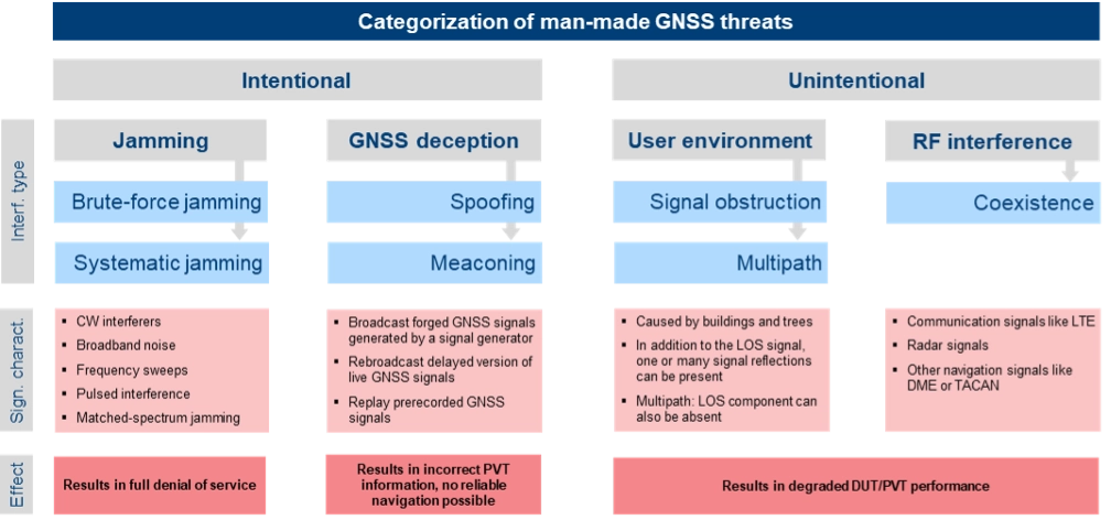
    Jamming can be divided into two types of attacks. Brute-force jamming aims at completely blocking GNSS reception for a receiver by deliberately emitting interference signals like CW interferers, broadband noise or frequency sweeps with very high-power levels. As a result, the carrier-to-noise values will drop below the receiver’s acquisition and/or tracking threshold, and GNSS signals cannot be processed anymore. In contrast to such a simple jamming attack, where the attacker needs to have only basic knowledge about the GNSS signals (e.g. center frequencies and signal bandwidths), systematic jamming is a much more sophisticated attack, which can be further divided into

    • Intelligent or smart jamming. The objective is to jam only a specific part of the navigation message (e.g. the ephemeris data section), so that the navigation message can never be fully decoded and the receiver will never be able to perform a position fix. All other parts of the navigation message remain unaffected, allowing signal tracking to continue for the receiver. Figure 2 illustrates this attack on the GPS L1 C/A signal.

    Photo:
    Figure 2. An intelligent jamming attack performed on a GPS L1 C/A signal.

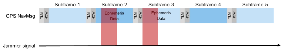
    Smart jamming is much more complicated to implement for an attacker as the jammer must only be active during specific time intervals; this requires that the jammer is somehow synchronized with GNSS/Coordinated Universal Time. Moreover, the attack requires knowledge of the navigation message structure and what information the receiver needs to compute a position. Nevertheless, if done correctly, the attack is rather difficult to detect [1].

    Matched spectrum jamming. The objective is to generate a GNSS-like jammer signal with the same spectral characteristics as the real GNSS signals but without any valuable navigation information (i.e. the navigation message is missing). Matched-spectrum jamming is not straightforward, and to be effective, an attacker must replicate the GNSS signals for multiple visible satellites simultaneously, considering signal characteristics such as pseudo-random noise codes and, ideally, their correct Doppler shifts.
    In contrast to jamming, GNSS deception techniques aim to force the receiver to compute an incorrect PVT solution, compromising the integrity of GNSS-based navigation. The two basic methods are:

    Meaconing. This rather simple approach is based on rebroadcasting a delayed version of live GNSS signals. This can be realized by using a commercial GNSS repeater. Alternatively, previously recorded actual GNSS signals can be replayed.

    Spoofing. This includes generation and broadcast of forged GNSS signals. This is typically done using a GNSS simulator, but specialized, modified GNSS receivers combined with a transmitting unit can also be used. The simulated signals need to be self-consistent, i.e. a GNSS receiver must be able to compute a PVT solution based on the simulated constellation. Spoofing attacks can be rather simple, e.g. broadcasting high power signals that represent a different location than those of the receiver under attack. The aim is to force the receiver into a reacquisition process, tracking and processing only the fake GNSS signals. More sophisticated spoofing attacks are possible [2], but not discussed in this article.

    Additionally, the PVT performance of a GNSS receiver can also be degraded by objects in the vicinity of a GNSS user, causing signal obstruction and reflections from buildings, trees, or the ground. Multipath can cause significant ranging and positioning errors. Multipath effects can hardly be avoided and must be seen as a permanent threat to GNSS signal quality.

    Finally, other existing signals and services can interfere with GNSS, either because there is a frequency overlap (in-band interference) or harmonics from other signals fall into the GNSS bands (out-of-band interference). As an example, the upper part of the DME/TACAN band overlaps with a significant portion the GNSS L5 band. The effect of this type of interference on GNSS receiver performance can be analyzed by performing coexistence tests.

    RX-Internal Detection and Mitigation Methods

    At least some of the threats discussed above can be detected and/or mitigated by the GNSS receiver. The capability of a GNSS receiver to detect and apply countermeasures to threats such as multipath, jamming or spoofing depends on the receiver’s availability of specific features and its basic architecture. Figure 3 shows the basic building blocks of a typical GNSS receiver with a single, fixed reception pattern antenna (FRPA).

    Figure 3. Basic architecture of a FRPA receiver

    Photo:

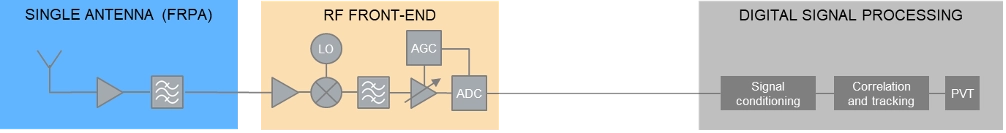
    The three basic building blocks are the antenna, the RF front-end and the digital signal processing section. The antenna is responsible for receiving the weak GNSS signals as well as for successive amplifying and band-limiting. It typically features a low noise amplifier (LNA) and a band-pass filter. The signals are then fed to the receiver front-end where the signals are amplified, down-converted to an intermediate frequency and converted to the digital domain. Part of this process is the automatic gain control (AGC) loop; the AGC acts as a variable amplifier, adjusting the power of the incoming signal and keep it constant over time. The sampled and quantized stream of IQ data is then fed to the digital signal processing section, where signal conditioning, acquisition and tracking, and PVT solution computations take place.

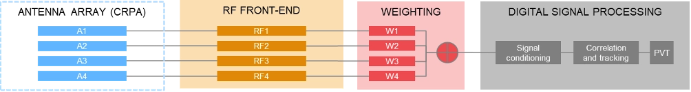
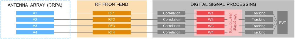
    In contrast to using a single antenna with a fixed antenna pattern, some receivers use an adaptive antenna array, also referred to as controlled reception pattern antenna (CRPA). The idea is to weigh the signals received by each element according to dedicated optimization criteria. Typical optimization criteria are to minimize the signal’s output power towards a dedicated direction (“null-steering”), or to maximize the signal to interference or signal to noise ratio (“beamforming”). The underlying receiver architecture is more complex as signal weighting mechanisms must be added to the signal processing chain. These can be integrated before the digital processing block (“pre-correlation”) or implemented as an additional processing step between the correlation and tracking stages in the digital signal processing section (“post-correlation”). Both approaches are very effective in mitigating jamming and spoofing attacks, as they can either form a null in the direction of a strong jammer/spoofer or form beams towards the wanted signals from GNSS satellites, thereby de-weighting any unwanted signals coming from other directions.

    Pre-correlation architecture of a 4-channel CRPA receiver
    Photo:
    Post-correlation architecture of a 4-channel CRPA receiver
    Photo:

    Within the processing chain of a GNSS receiver, there are different approaches and methods to detect and mitigate interfering signals, which are summarized in the following table:

    AGC monitoringMonitoring of the gain in the AGC loop. A sudden drop of the AGC gain can be an indication of an interfering signal; detection of high-power interferers; low-power spoofing attacks very difficult to detect
    Spectrum monitoringDetection of interferers and jammers above the noise floor; especially suited for detecting CW interferers. Not suited for the detection of matched-spectrum jammers, spoofers and meaconing attacks as their spectrum is typ. identical to the GNSS spectrum.
    Frequency domain adaptive filteringDynamically identifies and suppresses unwanted frequency components (e.g., interference or multipath) by adjusting (notch) filter parameters.
    Pulse blankingPulse blanking is a time-domain interference detection and mitigation technique used in GNSS receivers to detect and suppress short-duration, high-power pulses, typically caused by pulse jammers or Radar transmitters. Monitors the incoming signal power in short time windows and “ignores” this signal part in case certain power level thresholds are exceeded. Effective to mitigate pulsed jammers, not suited for multipath mitigation or anti-spoofing measures.
    C/N0 monitoringMonitoring over time and/or comparison against theoretical max. value; detection of all types of interferers; low-power spoofing attacks very difficult to detect
    Time jump detectionTime jumps (backwards or forwards) are clear indications for meaconing or spoofing attacks.
    PVT monitoring, incl. RAIMExample: The computed position can be constantly compared against a known reference position. Not possible to distinguish between jamming/spoofing or other environmental effects like multipath. This also includes receiver-autonomous integrity monitoring (RAIM) schemes, that can be considered as a special form of PVT monitoring.
    Doppler monitoringCompare Doppler against theoretical/geometrical values; monitored Doppler profiles may show irregularities in case of an attack. Difficult to be separated from environmental or atmospheric effects.
    CMC monitoring„Code minus Carrier“ observable shows irregularities and increased noise in case of an attack. Difficult to be separated from environmental or atmospheric effects.
    Signal Quality Monitoring (SQM)Sampling of the correlation function using a few correlators; can detect distortions of the correlation function resulting from multipath, jamming or spoofing attacks.
    Massive multi-correlator monitoringContinuous, high resolution observation of the code/Doppler space. Can be done during signal acquisition and tracking. Can detect multipath, jamming, meaconing and spoofing attacks.

    Derived Test Requirements

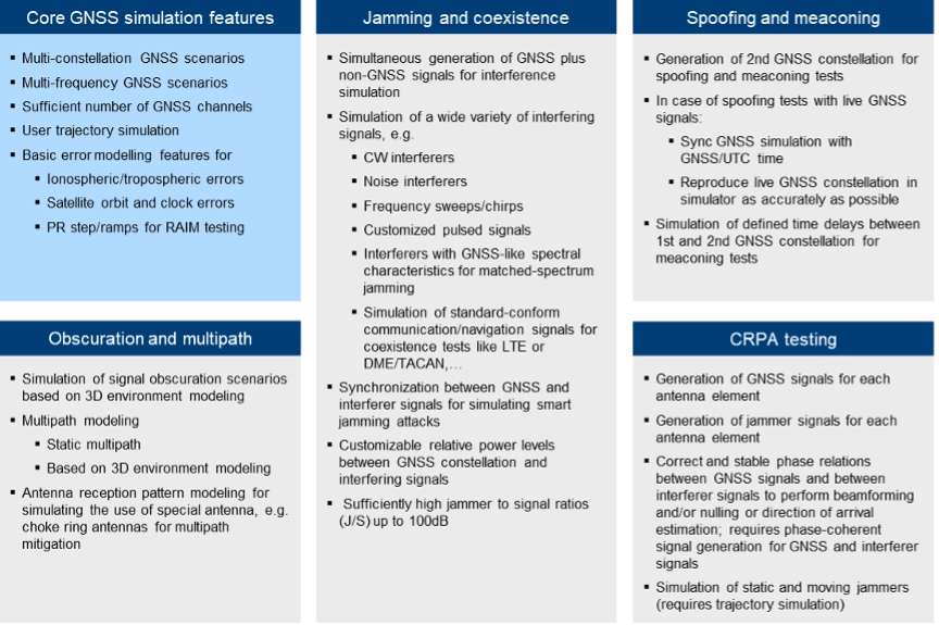
    Based on the typical threat signal and attack characteristics, as well as the receiver-internal detection and mitigation methods discussed above, the test and simulation requirements listed in the table below can be derived. In addition to the requirements related to threat simulations (grey background), the table also contains “base requirements” for the simulation of realistic GNSS scenarios (blue background):

    Photo:

    Testing: Methods, Setups and Challenges

    The test methods, strategies and setups used depend on the architecture of the GNSS receiver being tested, the receiver features that need to be evaluated and the specific testing objectives.

    A first categorization can be made by examining the origin of the GNSS signals being used for testing. The signals may come from real GNSS satellites and be used instantly and on-site (live GNSS testing) or recorded, stored, and played back in the lab (record/replay). Alternatively, testing can be done entirely in a lab environment using GNSS simulators. There are also hybrid test methods that will be discussed later in this article. In comparison to using real GNSS signals – either via live testing or the record/replay approach – using GNSS simulators in a lab environment offers significant benefits.

    Simulation vs. Live GNSS Testing. One major drawback of using live signals is that the system conditions are often unknown at a given point in time, and – most importantly – they change over time. The locations of the satellites — and thus the geometric conditions — change as the satellites move along their orbits. Errors, such as atmospheric effects, are also time- and location-dependent. One of the most unpredictable error influences is multipath. The magnitude of multipath errors depends on a variety of different parameters, including the number of reflections, the distance between the reflection points and the antenna or the strength of the reflected signal. The latter is determined by the material properties of the reflecting surface. Both the geometric conditions and the material properties of the reflectors change or may change over time – the geometric conditions due to the permanent motion of the satellites and the reflector properties due to meteorological influences like rain, dew, or snow.

    As a result, when using live signals, one must expect that the conditions change permanently and unpredictably and will never be the same for two distinct points in time. It is therefore very unlikely that two successive test runs can be performed under identical conditions. Repeatable testing, which is one of the most important test requirements, is impossible when using live GNSS signals.

    Well-defined and controlled simulation conditions can only be ensured by using a GNSS simulator. A simulator typically offers fully customizable and repeatable scenarios (i.e., one and the same test scenario) that can be repeated as often as needed, producing the same signals with the same characteristics. Moreover, a simulator is often a more cost-effective and efficient solution, whereas using live signals would be time-consuming, complex, expensive or even impractical (e.g. test of airborne and spaceborne receivers).

    The following discussion of typical test setups therefore focuses on the use of signal generators for GNSS testing. In terms of test scenarios, the focus will be on jamming, spoofing and coexistence testing. Testing against multipath influences is not specifically discussed below.

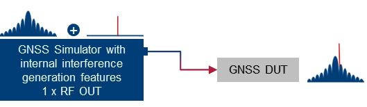
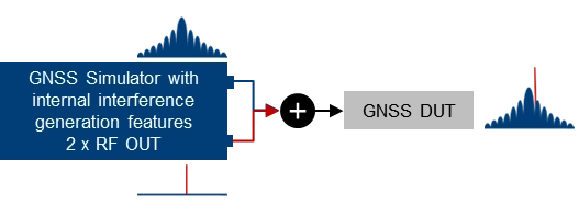
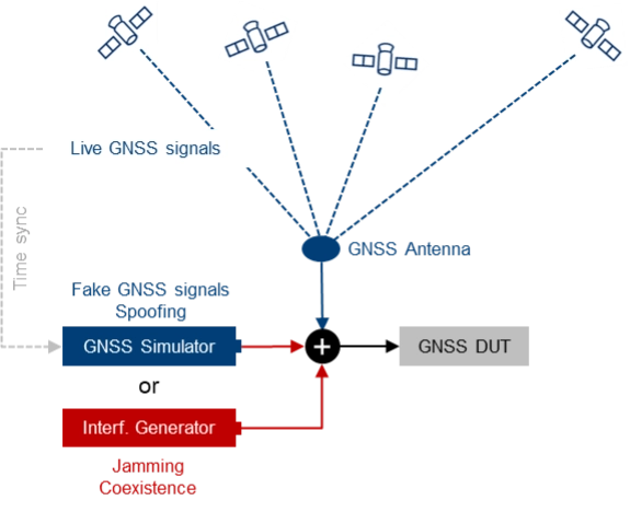
    Basic simulator setups. The basic approach for testing against GNSS threats is to combine a “clean” reference GNSS simulation scenario with interfering signals and add the combined signals to the device under test (DUT). This basic concept can be implemented using two separate signal generators or an integrated solution that combines GNSS simulation and threat signal generation in a single instrument. Based on the architecture of the integrated solution (1 RF output vs. multiple RF outputs), GNSS and interfering signals are already combined internally, or GNSS and interfering signals can be fed to different RF outputs and combined with an external combiner before fed to the DUT.

    Using two separate signal generators for GNSS threat testing. The interference generator (red) can either be a second GNSS simulator for generating spoofing signals or any other signal generator providing non-GNSS signals for jamming or coexistence tests. 
    Photo:
    Using a GNSS simulator with integrated interference generation capabilities. The signal generator features 1 RF outputs. GNSS and interfering signals are combined internally. An external combiner is not needed, but the dynamic range between GNSS and interferer (J/S) is usually limited.
    Photo:
    Using a GNSS simulator with integrated interference generation capabilities. The signal generator features 2 RF outputs. GNSS and interfering signals fed to individual RF ports and combined externally. This requires an external combiner, but with the benefit that very high J/S ratios can be achieved.
    Photo:

    Conducted testing vs. OTA testing. The basic setups introduced above only work if the receiver has dedicated and accessible input connectors to feed the antenna signal to the receiver’s front end. This is sometimes not the case, so that conducted testing is not possible and over-the-air (OTA) tests must be considered. A classic example of such DUTs is mobile phones, where no antenna connector is available, at least not without dismantling the device.

    Testing such devices against interfering signals is still possible by using a shield box. The shield box has an RF input to feed in the combined GNSS and interfering signals. The signals are then retransmitted into the inside of the box and the DUT uses its integrated antenna to receive and process the signals coming from the GNSS simulator.

    Using a GNSS simulator in combination with a shield box to test GNSS devices with integrated antennas.
    OTA GNSS threat simulation using a shield box with 2 RF inputs and 2 transmit antennas. The GNSS signals and the interfering signals are fed separately (uncombined) into the shield box.  

    An alternative setup is to use a shield box with two RF inputs. In this case, the wanted signals and the interfering signals are not combined externally but are fed to the shield box via separate RF input connectors and transmitted to the GNSS DUT via separate transmit antennas.

    Additional aspects and challenges must be considered when performing OTA tests using mobile phones as a GNSS DUT. This includes conducting a proper cold start, removing all preexisting navigation-related information from its memory, and disabling any other sensors that may contribute to computing the phone’s position, including any assisted GNSS services. This is typically not a concern for most standalone GNSS receivers that feature dedicated cold start procedures and usually have no other positioning sensors on board. On the other hand, initiating a real cold start for GNSS modules in mobile phones can be tricky. Just rebooting the phone does not necessarily work, and the availability of dedicated settings also depends on the phone’s operating system (e.g. iOS vs. Android).

    Another challenge during OTA testing of mobile phones is how to assess and analyze the impact of any interfering signals on signal acquisition, tracking and positioning. This requires detailed analysis and monitoring features on the mobile phone, which are typically not a standard feature of the phone’s operating system. Specialized GNSS monitoring apps can be used instead. To get access to the data during the test, special screen mirroring apps can be installed on the mobile phone.

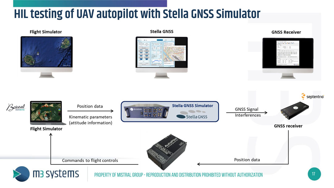
    Testing with live signals. GNSS tests may also be performed in combination with live GNSS signals using already existing field infrastructure such as GNSS receivers installed at mobile base stations. A typical use case is to add one or several jamming/spoofing signals, or even an entire (stronger) “spoofing constellation” to an existing “live GNSS constellation” and test how the GNSS receiver reacts to such an attack. The typical test setup is illustrated in Figure 4.

    Photo: Figure 4. The receiver’s response to interference is evaluated by introducing jamming or spoofing signals, alongside normal satellite signals using existing field infrastructure. This setup is often used to assess reactions to attacks.
    Photo: Figure 4. The receiver’s response to interference is evaluated by introducing jamming or spoofing signals, alongside normal satellite signals using existing field infrastructure. This setup is often used to assess reactions to attacks.

    This approach may be a good alternative to simulating everything with a GNSS simulator, as much more HW, i.e., more GNSS channels and more RF paths, are required with a simulator-internal approach. On the other hand, there are also some challenges associated with this test method, e.g., the signal generators, which need to be operated in a field environment. Moreover, for more sophisticated spoofing attacks, a prerequisite is the capability to time-synchronize the GNSS simulation with the live GNSS constellation.

    CRPA testing. For testing GNSS receivers with multiple antenna inputs, particularly CRPA systems, several RF sources/paths need to be combined and synchronized. The following illustration shows a possible setup for testing a 4-channel CRPA receiver against jamming or spoofing attacks. It is based on the 2-path architecture introduced above. It consists of two signal generators for generating GNSS signals for each antenna (left part of the setup) and two signal generators for generating the jammer/spoofer signals (right part of the setup). GNSS and interfering signals are combined per antenna element and fed to the RF inputs of the CRPA receiver under test.

    Photo:

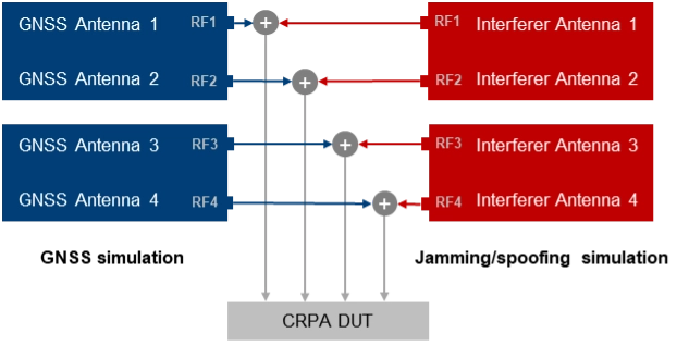
    For CRPA testing, generating phase-coherent signals is a must, i.e., it must be ensured that the phase relations between the GNSS signals and between the interfering signals represent the actual geometrical conditions and, above all, remain consistent throughout the simulation. To achieve this, a common LO signal needs to be used for generating the GNSS and interferer signals in all signal paths.

    Another challenge is related to calibration. To correctly simulate the directions of the satellite signals and the interference signals, the test system must be calibrated at the RF interface to the DUT with respect to amplitude, phase and propagation time. This means that the amplitude, phase and propagation time differences between the individual RF paths, resulting for example from cables orRF components, must be compensated.

    Rohde & Schwarz Solution

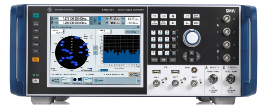
    With GNSS test solutions from Rohde & Schwarz, all the relevant requirements for testing GNSS receivers against GNSS threats can be addressed. Available test solutions range from simple, single-channel, waveform-based signal generation with limited simulation time up to multi-frequency, multi-constellation GNSS simulators with 2 RF outputs, hundreds of GNSS channels and internal threat simulation capabilities, including non-GNSS signals for jamming and coexistence tests. For these advanced GNSS tests, the R&SSMW200A high-end vector signal generator is the ideal choice. It can be equipped with a multitude of GNSS options and feature sets.

    Photo:
    Photo: Testing against GNSS threats with the R&S SMW200A

    Jammer simulation. There are several ways to generate jamming and coexistence signals with Rohde & Schwarz signal generators in general and especially with the R&SSMW200A. Simple interference signals like noise or a CW interferer can be generated by using an optional integrated noise generator. For coexistence testing, the instrument can be equipped with signal generation capabilities for various standard-conforming communication signals, such as LTE. Customized interferer signals in the form of waveform files can be created by external software tools like MATLAB or Python and replayed by the instrument.

    Customized jamming signal as well as entire jamming and coexistence scenarios can also be created using the R&SPulse Sequencer. The software allows to generate typical simple GNSS jamming signals like CW interferer, frequency sweeps, or pulsed interferers, but also complex jamming scenarios with consideration of moving interference sources and moving GNSS receivers, user-defined antenna patterns and scans. Depending on the signal characteristics, the jammer and receiver positions and the antenna arrangement, the software calculates the correct amplitude, phase angle and signal propagation times for the jamming signals.

    Further reading

    [1] Curran, James T. et. al. (2017): A look at the Threat of Systematic Jamming of GNSS, InsideGNSS, September/October 2017

    [2] Dovis, Fabio et. al. (2015): GNSS Interference Threats and Countermeasures, GNSS Technology and Application Series, Artech House, 2015

  • Safran’s Skydel simulator now supports Xona’s Pulsar LEO navigation signals

    Safran’s Skydel simulator now supports Xona’s Pulsar LEO navigation signals

    Safran Electronics & Defense‘s Skydel GNSS simulation platform is now fully certified to support simulation of Xona Space Systems’ low-Earth orbit positioning, navigation and timing (LEO-PNT) signal, Pulsar.

    According to the companies, this certification is the culmination of a rigorous multi-phase validation program jointly led by Safran and Xona engineering teams. It underscores Safran’s commitment to advancing robust, high-fidelity testing for next-generation LEO-PNT services. With this milestone, engineers can now use Skydel to evaluate Pulsar’s performance in environments that reflect real-world complexity, interference and operational demands.

    Skydel now simulates Xona’s Pulsar X1 signals, delivering centimeter-level precision, 100x signal strength and enhanced resilience — capabilities that Pulsar will soon bring to orbit.

    “With Skydel-powered simulators certified for Pulsar X1, our customers have more possibilities than ever,” said Pierre-Marie Le Veel, program director of PNT simulation at Safran Electronics & Defense. “They can test LEO and legacy constellations side by side, introduce complex interference, and explore entirely new scenario combinations — all from a single, flexible platform. This is a major step forward in enabling engineers to push the boundaries of GNSS testing.”

    Beyond accuracy, Skydel enables advanced resilience testing, including jamming, spoofing and other NAVWAR threats. Its modular, future-ready architecture ensures seamless integration of new Pulsar signal types and constellation updates, offering the agility needed to keep pace with the evolving LEO PNT landscape and demands for trusted, high-integrity PNT.

    “Validation is the bridge between innovation and trust,” said Tyler Reid, CTO of Xona. “By replicating Pulsar at full fidelity, Skydel empowers engineers to design and validate solutions for the most demanding navigation and timing challenges — without waiting for on-orbit availability.”

    Skydel’s certified Pulsar simulation capability is available now to partners and customers worldwide.

  • Safran launches AI tool for GNSS simulation automation

    Safran launches AI tool for GNSS simulation automation

    Safran Electronics & Defense has unveiled Skydel AI, a breakthrough in GNSS simulation technology that uses artificial intelligence (AI) to automate and simplify simulation scenario setups.

    Skydel AI streamlines GNSS simulation scenario creation through intelligent automation and an intuitive interface. Using natural language commands, Skydel AI allows users to query GNSS/Skydel topics, request assistance and dynamically configure simulation parameters by creating Python code for use by Skydel. The technology eliminates complexity and significantly reduces setup time.

    “Soon available as part of Safran’s Support offerings, Skydel AI can help customers drastically improve their development cycles by accelerating manual scenario tuning and reducing long test cycles within Skydel,” said Pierre-Marie Leveel, program director for PNT at Safran. “Already established as the most flexible, robust, and accurate GNSS simulation engine, Skydel never stops innovating and delivering what the market requires – whether it is more realism, higher accuracy, more environment complexity, or ease of use.”

    The company also introduced an AI-powered tropospheric model that enhances Skydel’s tropospheric simulation using real-time weather data and AI predictions to improve wet delay accuracy. Integrated with the Open-Meteo API and Skydel’s system, it relies on a neural network trained on 14 million samples from 221 GNSS stations, delivering up to 88% more accuracy. This model will be available in a future Skydel release.

    The technical breakthrough reflects Safran Electronics & Defense’s commitment to redefining GNSS simulation with intelligent, adaptable and high-performance solutions for mission-critical applications.

  • Qascom delivers Moon test bed

    Qascom delivers Moon test bed

    Qascom S.R.L. (IT) has successfully delivered the final presentation of the NAVISP-EL2-081 –  MOOD  (Moon testbed) project, marking the culmination of a multi-year effort to develop a cutting-edge GNSS simulation testbed for lunar, cislunar and space-based PNT applications.

    For this purpose, Qascom upgraded its QA707 GNSS simulator introducing advanced features such as lunar-specific ranging strategies, support for multiple coordinate reference systems, custom signal transmitters (including LunaNet AFS), and a 3D Viewer for real-time scenario visualization. It also integrates BeiDou B1C signal simulation and dual-frequency RF streaming capabilities.

    Key achievements include successful validation of LunaNet and BeiDou signals, implementation of Moon Principal Axis (Moon-PA) ranging, and integration with open-source and COTS receivers. The simulator has already supported the project NAVISP-EL1-062 – DEMOS-1(Lunar Surface PNT Beacon Demonstrator) and is now Qascom’s flagship GNSS simulation product.

    Looking ahead, Qascom plans to enhance QA707 with direct dual-frequency RF output and integration with SDR hardware, being developed under the project NAVISP-EL2-090 – JNRS (Joint Navigation Radio System).

    The project was supported through NAVISP Element 2 for PNT competitiveness for European industry. The slides of this final presentation can be found here.

  • Safran Federal Systems upgrades BroadSim product line

    Safran Federal Systems upgrades BroadSim product line

    Safran Federal Systems introduced BroadSim Genesis, the latest addition to its BroadSim product line, at the Institute of Navigation’s 2025 Joint Navigation Conference in the Greater Cincinnati area.

    Developed for the U.S. defense community, BroadSim Genesis advances GNSS simulation and NAVWAR testing with significant improvements in signal capacity, operational flexibility and user experience. The system delivers high-fidelity, threat-representative environments designed to support next-generation positioning, navigation and timing (PNT) resiliency.

    BroadSim Genesis can generate up to 2,000 signals, enabling advanced multi-constellation simulations across medium Earth orbit, low Earth orbit and alternative PNT sources within a single test environment. The system is engineered to meet modern NAVWAR requirements, supporting multi-antenna and multi-vehicle configurations, M-Code, and integrated jamming and spoofing capabilities to counter sophisticated signal threats.

    The user interface features an integrated front panel with N-type connectors, removable drives and an onboard timing card, offering ease of use, security and field readiness.

    “BroadSim Genesis is built for operators who demand flexibility, fidelity and performance in their GNSS simulation tools,” said Trevor Dougherty, vice president of sales at Safran Federal Systems. “Whether validating mission equipment, training for NAVWAR scenarios or assessing new PNT architectures, BroadSim Genesis gives defense users the edge they need”

  • LabSat launches scalable solutions for GNSS signal testing

    LabSat launches scalable solutions for GNSS signal testing

    LabSat has expanded its GNSS signal record, replay and simulation portfolio with the introduction of three new LabSat 4 variants: LabSat 4, LabSat 4 Core and LabSat 4 Lite. LabSat seeks to provide engineers and developers with scalable solutions tailored to a wide range of testing requirements and budgets.

    LabSat 4 delivers advanced capabilities, including up to 12-bit I&Q quantization and support for recording and replaying external data such as CAN-FD, RS232, and digital inputs. This model is designed for demanding GNSS signal testing, offering high precision and extensive customization to address complex modern testing scenarios.

    LabSat 4 Core offers the same features as the original LabSat 4, except it is limited to a maximum of 4-bit I&Q quantization. This makes it a cost-effective choice for applications where the highest signal capture resolution is not necessary, while still providing a comprehensive feature set.

    LabSat 4 Lite is optimized for affordability, featuring streamlined 2-bit I&Q quantization and omitting external data recording and replay. It is well-suited for production line testing and other scenarios where quantization depth is not a critical factor.

    All LabSat 4 variants include three RF channels with selectable bandwidths up to 60 MHz, adjustable quantization options depending on the model, manual gain control, multi-unit synchronization, and full backward compatibility with LabSat 3 Wideband file formats. The series is compact, portable, and designed for efficient use in both field and laboratory environments.

    A key benefit of the LabSat 4 range is the ability to upgrade between models via a license file, allowing users to start with LabSat 4 Lite and move to Core or the full LabSat 4 as their testing needs evolve, without replacing hardware. Customers can also select between Replay-Only and Record-and-Replay configurations across all variants.

  • JAXA selects Spirent’s PNT simulation solution for lunar navigation program

    JAXA selects Spirent’s PNT simulation solution for lunar navigation program

    The Japan Aerospace Exploration Agency (JAXA) has selected Spirent Communications to supply its lunar positioning, navigation and timing (PNT) simulation solution. The solution will support JAXA’s lunar exploration efforts and aid in developing essential navigation infrastructure for future moon missions.

    Spirent’s PNT X solution allows JAXA to simulate lunar PNT services in a controlled laboratory setting before their deployment on the moon. This capability is critical for testing and validating navigation equipment for lunar missions in accordance with the emerging LunaNet specifications, which include adaptable S-band frequency solutions. The system also ensures scalability for future space exploration.

    Using the PNT X system, JAXA can experiment with novel S-band signals and evaluate the performance of receivers that rely on standalone S-band Lunar PNT signals or a combination of Lunar PNT and Earth-based L-band GNSS infrastructure. The simulation of these signal combinations demands high levels of precision, which Spirent’s specialized architecture is designed to meet.

    This collaboration builds on a longstanding relationship between Spirent and JAXA. In 2011, JAXA utilized Spirent’s simulation technology to verify the performance of early Quasi-Zenith Satellite System (QZSS) receivers. Since then, Spirent simulators have supported multiple advancements in QZSS.

    Spirent’s lunar PNT simulation solution seeks to present new opportunities for space agencies developing lunar constellations, satellite and receiver developers and organizations planning lunar missions or seeking to establish additional PNT infrastructure on the moon.

  • Labsat shares results of Jammertest 2024

    Labsat shares results of Jammertest 2024

    Labsat has released updates from Jammertest 2024, where the team addressed real-world challenges related to GNSS jamming and spoofing attacks. According to Labsat, the team was on-site with the Labsat 4 GNSS Record & Replay device, which effectively captured the entire GNSS RF environment during the tests. The team shared that this technology has allowed Labsat to collect more than 20 TB of data, enabling them to reproduce complex signals under laboratory conditions.

    Labsat recorded GNSS signals at 12 bits of I&Q resolution across multiple frequency bands to accurately capture the RF conditions. With this data, LabSat 4 users can recreate these signals on their test benches, allowing them to evaluate their GNSS receiver performance against the same challenges encountered during the event.

    Labsat said it plans to make these recordings available to its LabSat 4 users, allowing them to experience a full range of jamming and spoofing scenarios firsthand. This offers GNSS engineers a unique chance to prepare their technology for real-world threats.

    Photo:
    Labsat 4 GNSS Record & Replay device. (Photo: Labsat)

  • Safran unveils GNSS/PNT simulator

    Safran unveils GNSS/PNT simulator

    Photo: Safran Navigation and Timing
    Photo: Safran Navigation and Timing

    Safran Navigation and Timing has unveiled its latest GNSS simulator, the Skydel GSG-8 Gen2, an evolution of its GSG-8 simulator. This new positioning, navigation and timing (PNT) test solution is part of Safran’s family of Skydel-based simulators.

    The GPU-based GSG-8 Gen2 simulator delivers high-end GNSS signal testing capabilities in a user-friendly, turnkey package. It seeks to support the growing demand for location-aware applications and systems requiring navigation or timing.

    It features six front-facing RF outputs and a combined output. It covers the entire GNSS bandwidth and offers a 1,000 Hz simulation iteration rate, high dynamics, real-time synchronization and simulation of all-in-view satellite signals.

    This simulator is ideal for development, NavWar testing and integration projects that require high performance, increased constellation and satellite visibility and multi-vehicle/multi-antenna scenarios. It allows users to generate RF signals that simulate real-world receiver device reactions under user-defined parameters. Users can control various simulation aspects, including receiver trajectories with six degrees of freedom (DoF), multipath signals, advanced jamming and spoofing and atmospheric interferences.

    The simulator can recreate various types of interference, both benign and malicious. Users can adjust power levels, interference signal types, spoofing signals, location, antenna patterns, and transmitter trajectories. In-band and out-of-band jamming signals can be generated without additional hardware.

    The GSG-8 Gen2 can simulate up to 2,000 GNSS signals simultaneously across multiple bands, leveraging GPU power to overcome the limitations of FPGA-based simulators. A single GSG-8 Gen2 can run and control multiple instances, each representing an independent trajectory, vehicle or antenna with its own output connector.

    As a low-Earth orbit (LEO) PNT signal simulator, the GSG-8 Gen2 can generate many signals required for LEO PNT simulations alongside legacy GNSS signals, threats and multipaths. It also supports S-Band signal generation.


  • Simulating new GNSS signals and threats

    Simulating new GNSS signals and threats

    The Spirent PNT X. (Photo: Spirent Federal Systems)
    The Spirent PNT X. (Photo: Spirent Federal Systems)

    Developers and manufacturers of GNSS receivers have always needed to simulate the signals from GNSS satellites to test receivers in their labs and in the field. Now, as the vital role of GNSS for critical infrastructure and the growing threat of radiofrequency attacks are increasingly recognized, simulators must keep up. In particular, they must enable users to test a variety of new positioning, navigation and timing (PNT)  signals from satellites in low-Earth orbit (LEO) and geostationary orbit (GEO), as well as realistically simulate sophisticated jamming and spoofing attacks.

    In this cover story on simulators, we discuss these challenges with experts at four simulator manufacturers:

    • John Clark, Vice President, Engineering, CAST Navigation
    • Lisa Perdue, Product Line Director, Safran Federal Systems
    • Jan Ackermann, Director Product Line Management, Spirent Communications, and Paul Crampton, Senior Solutions Architect, Spirent Federal Systems
    • Avag Tsaturyan, Systems Engineer, M3 Systems.

    How are the missions/applications of simulators changing?

    Clark: Our customers have been requesting larger simulation systems that can support GNSS and inertial navigation systems (INS) on multiple vehicles simultaneously. Each vehicle is required to support a phased-array (CRPA) antenna sub-system, multiple INS interfaces and signal interference capabilities. This is a change from earlier times when our customers required smaller systems with less capability.

    Perdue: We see a growing focus on testing NAVWAR scenarios and assessing receiver performance against diverse threats. The increasing complexity of receivers with multiple constellations and frequencies demands more advanced simulation capabilities. We provide comprehensive PNT simulators that support hybrid scenarios, in which simulated signals and threats are combined with live signals and sensors, creating a dynamic and realistic testing environment.

    Crampton: For many years, simulators have been used to prove the capability of receivers and the systems into which the receivers are integrated. Testing ensures that receivers can perform as expected, including performance in boundary cases, which are tricky to recreate in live-sky conditions.

    Over time, threats to navigation and timing performance began to dominate the schedules of test labs. Ensuring reliable performance in suboptimal operating environments is critical to receiver users. The workload of test labs has increased to the point where test automation has become necessary, not only in terms of increased efficiency but also just to keep pace with rapidly evolving threat profiles.

    So, one of the main changes we are seeing is the need to speed up the innovation cycle with simplified, automated testing while maintaining test fidelity and robustness. Spirent simulators are enabling testing to “shift left,” to start testing earlier in the development cycle with digital twins — software-only models of receivers and devices — to shorten the time spent on R&D.

    Ackermann: Increasing efficiency, flexibility and realism have been critical drivers in the simulator industry for many years and will continue to drive us forward at an ever-increasing pace. Precision and robustness requirements demand more signals and sensor fusion, which need to be supported by simulators. Greater realism and flexibility means that more representative testing can be done in the lab, saving time and money.

    On the other hand, while lab testing has grown ever more realistic, there are times where in-field verification is required — simulators have had to become more flexible to address this “augmented reality” test environment and optimize field testing. Simulators are being used on ranges to enhance testing, using combinations of real and simulated signals — including resiliency tests that incorporate live-sky signals.

    Are new markets for simulators emerging?

    Clark: Yes, as the world evolves and circumstances change, the ability to validate proper operations of GNSS and GNSS/INS navigation systems under less-than-optimal conditions has become challenging. The use of simulators can greatly enhance your understanding of the behavior of a navigation system, thus allowing for more reliable navigation error planning and mitigation when these errors do occur. This has become a much more important area of concern as the automated navigation and integrated navigation markets mature.

    Perdue: Yes, new markets are emerging in areas such as autonomous vehicles, UAV swarms, urban air mobility and space exploration, including lunar missions. Additionally, the growing focus on cybersecurity and electronic warfare has increased the demand for simulators that can replicate complex cyberattack scenarios and electronic threats.

    Ackermann: New markets for simulators are constantly emerging. As PNT impacts more and more areas of our lives, the geographic and technological spread of simulator requirements continues to expand. Even in existing segments we see new market needs. In automotive, for instance, the emergence of a wide range of safety-critical functions such as intelligent speed assist (ISA) and eCall drive new simulation needs.

    From the emergence of the LEO market to the development of LEO PNT constellations, these markets appear and evolve at a rapid pace. Spirent simulators can be used to generate novel and established signals from LEO PNT constellations with ultra-realistic orbital models for complex rotational effects and satellite parameters. The emerging focus on lunar missions from space agencies around the world means new test environments, more stringent requirements, and the potential for new signals outside of L-band, at S-band and beyond.

    Crampton: Increasing the realism of testing continues to open new opportunities for simulator use. Spirent provides an all-in-one alternative PNT solution for ultra-realistic LEO modeling, inertial emulation, L and S-band signals, etc. — to be fused and tested in unison.

    Senior Software Engineer Neil O’Brien utilizing a CAST-8000 GNSS Simulator to analyze CRPA trajectory data. (Photo: CAST Navigation)
    Senior Software Engineer Neil O’Brien utilizing a CAST-8000 GNSS Simulator to analyze CRPA trajectory data. (Photo: CAST Navigation)

    Are simulator requirements changing?

    Clark: In the past our customers were focused on the simulation of a single element of GNSS signals and a single INS output interface for the testing of vehicles that only supported single element antenna (FRPA) and a single INS capability. Our customers are now requiring simulator systems that produce multiple elements of phase-coherent GNSS signals that are commensurate with multiple INS interface outputs to drive navigation systems that can utilize a phased-array multiple-element antenna sub-system (CRPA) and multiple INS sources simultaneously.

    Perdue: Yes, simulator requirements are always evolving. High signal counts are essential due to the increase in LEO constellations, and there’s a need to replicate multiple threats to create realistic environments. Built-in automation is crucial for managing these complex scenarios. The ability to add custom signals and constellations is necessary for experimenting with new technologies. Our software-defined architecture allows for quick integration of new signals, ensuring flexibility and responsiveness to changing needs. Innovations such as a radio utilizing the RFSoC to provide a high number of multi-frequency outputs from a single system and the BroadSim Duo, which offers dual-frequency capabilities in a compact form factor, demonstrate our approach to meeting these evolving requirements.

    Ackermann: As new markets and use cases emerge, the simulator requirements evolve. The growing prevalence of NAVWAR threats, such as GNSS jamming and spoofing, and the range of systems these attacks are impacting is enhancing the criticality of lab testing.

    Whether seeking to gain battlefield advantage or to secure civil operations (aviation, for instance), the ability to generate a wide range of NAVWAR attack vectors in complex scenarios is needed like never before. New waveforms must be incorporated quickly and realistically, while defensive technologies such as CRPAs must be exercised with a higher level of precision.

    Crampton: Due to the demand for flexible attack vectors and the expanding range of available signals, simulators need to be capable of generating authentic RF environments from novel, user-defined waveforms. A time-saving method has been developed using prerecorded I/Q files. Spirent’s sixth-generation solution, PNT X, accepts raw I/Q data, analyzes the environment and the dynamic movement between receiver and transmitters, and automatically applies the correct motion effects to the generated RF signal. The simulated signal now has real-world dynamics without the need for manual inputs from the user. Realism made simple! Additionally, multiple I/Q-defined transmitters can be seamlessly integrated with native 3D terrain-modeling capabilities to create rich RF environments with multipath and obscuration.

    A continuous, dynamic range is required to better replicate high-power jamming threats for controlled reception pattern antenna (CRPA) testing. With PNT X, high-power jammers can be simulated from the moment they become part of the noise floor to when a vehicle, such as an aircraft using a CRPA, passes by it. This continuous range enables CRPA developers to characterize null-steering ability with greater precision than previously possible.

    Ackermann: As previously mentioned, there is also a growing need for integration and automation. Systems need to work in concert, and testing needs to happen quickly and efficiently to stay ahead of markets and threats. To this end, the ability to automate and to control remotely, and the ability to integrate seamlessly with other simulation and control systems, are core requirements for modern labs. Spirent is simplifying and automating testing with support for multiple industry-standard frameworks.

    In established markets, safety requirements on devices under test drive simulator needs. For instance, functional safety requirements for automotive applications demand the ability to simulate threats and events, while the fidelity requirement of the simulation is elevated to assure conformance.

    3D view of an aircraft flying a simulation. (Photo: CAST Navigation)
    3D view of an aircraft flying a simulation. (Photo: CAST Navigation)

    What mix of signals do you support?

    Clark: GPS L1/L2/L5, L1C, L2C, C/A, SBAS, P, Y, SAASM, M-Code AES and MNSA, Glonass and BeiDou

    Perdue: We support a wide array of signals, including GPS, GLONASS, Galileo, BeiDou, and regional systems such as QZSS and IRNSS. Additionally, we incorporate alternative navigation signals, such as those from Xona, and support inertial navigation and timing signals. Our software-defined architecture enables us to handle high signal counts and allows for extensive customization, ensuring we can simulate any required signal environment. This flexibility ensures we meet the diverse needs of various industries and applications, from aviation and maritime to autonomous vehicles and defense.

    Ackermann: Spirent supports all open service GNSS signals and classified GPS testing — including M-Code Regional Military Protection — as well as PRS (through prs[ware] and our partnership with Fraunhofer IIS) on our simulation platforms.

    In addition:

    • Regional systems (e.g., NavIC or QZSS)
    • S-band frequency signals
    • Custom non-ICD signals
    • LEO PNT (Xona Space System’s PULSAR and others)
    • A broad range of interference waveforms, including CW, FM, PM, wideband AWGN, chirp, matched spectrum, etc.
    • Generation of RF from I/Q data injection in L-band and S-band frequencies
    • Correction/augmentation
    • Inertial sensor emulation

    Furthermore, the ability to geolocate custom RF beacons either in a range of orbits or in terrestrial locations adds huge signal flexibility.

    What are the key challenges you face?

    Clark: As our customers’ needs grow and evolve, some of our key challenges have been the ability to continue to evolve our product utilizing cutting-edge technology while still maintaining backwards compatibility with our older technologies. Efforts like this give our customers peace of mind when making a system purchase and enable them to take full advantage of prior purchases when requirements change and system enhancements are necessary.

    Perdue: A key challenge is creating complex simulation environments that require specialized expertise. Customers often lack the knowledge to design these environments effectively. Ensuring simulation accuracy and cybersecurity are significant concerns, especially as new threats emerge alongside new technologies developed to combat existing threats. Translating performance requirements into practical specifications and meeting stringent industry standards adds another layer of complexity. We address these challenges through continuous updates and close collaboration with our customers to ensure our solutions meet their evolving needs.

    Ackermann: For 40 years, we have faced a challenge that, to some degree, is being addressed. Namely, PNT is not widely standardized and therefore test requirements are highly diverse. The scale of Spirent and the empowering flexibility of our systems enables us to overcome this, but it remains challenging.

    The current geopolitical situation also presents challenges, as the number of threats and the potential for negative events demand ever-increasing sophistication in testing. That’s why we built PNT X with high-power jamming and spoofing capability for greater realism and accurate test results.

    Crampton: The complexity of next-gen positioning engines means that our systems have to integrate and interact with other systems, built by other companies with other protocols and specifications. Spirent maintains the precision and stability our customers expect from us while incorporating an open and controllable architecture for easier plug-and-play in complex hardware-in-the-loop environments.


    M3 SYSTEMS

    Please introduce your company.

    Tsaturyan: We represent the Mistral Group, which includes three distinct companies: M3 Systems France, M3 Systems Belgium and Boreal. M3 Systems France teams provide GNSS simulation and test and measurements solutions and radionavigation and signal processing expertise. M3 Systems Belgium teams are experts in air traffic management (ATM) studies. Boreal teams offer beyond-line-of-sight missions for maritime surveillance, Earth observation, and scientific experiments with the BOREAL long-range unmanned aircraft. Each company extends its scope to the challenges of GNSS and UTM with an integrated approach.

    What are your key markets? What challenges are you addressing?

    Our customers are from different industries: we work with space agencies — such as France’s Centre National d’Études Spatiales (CNES) and the European Space Agency (ESA) — private R&D labs and automotive companies and railways. We propose GNSS simulation products such as the Stella GNSS simulator, which allows users to simulate a vehicle in a realistic environment and in real time for low latency. Our simulator is designed to reproduce the sky with high precision. The GNSS signal passes through different layers, each one of which has a different effect. First, there can be an error in the satellite clock, then there can be a delay as the signal passes through the atmosphere, then, on the ground, there is a risk of a spoofing or jamming attack and, in urban areas, multipath from buildings.

    What signals does your simulator support?

    Our GNSS simulator is multiconstellation and multi-frequency. It supports all the available GNSS signals and frequencies. Users can simulate multiple antennas and multiple trajectories, custom atmosphere and multipath effects. We offer several built-in models of multipath. Users also can use their own multipath models and even integrate it with an SE-NAV multipath simulation tool. We also have several built-in jamming signals that users can apply and spoof the real signal coming from the antenna or spoof the simulated signal. Our setup now also supports Galileo’s Open Service Navigation Message Authentication (OSNMA). Our Stella GNSS simulation software can run on three different products designed for specific needs: the Stella GNSS Simulator Base (based on NI’s USRP kit), the Stella GNSS Simulator Suite (based on our bundle), and the Stella GNSS Simulator Advanced (based on NI’s VST). Our VST-based solution is optimized for tests that require high performance in terms of calibration — such as simulating a CRPA antenna, where the channels need to be very tightly synchronized.

    Photo: M3 Systems
    Photo: M3 Systems

    What does your Stella Suite do?

    The Stella GNSS Simulator offers up to two independent RF simulations, enabling simultaneous simulation and the jamming/spoofing or the simulation of multiple antennas and trajectories.

    Our simulator suite is basically an all-in-one device that allows users to plug in a receiver. This single device enables  users to simulate jamming, spoofing, multiple antennas or multiple trajectories.

    When did you launch this product?

    We released it and demonstrated it during Emerson NI’s “NI Connect” event. They have an annual event in May in Austin, to which they invite all their partners and customers. This year, we were invited there to present our new simulator. We brought a HIL test setup to demonstrate the new configuration of our GNSS simulator: a closed-loop test of a drone autopilot system. When kinematic parameters from the flight simulator are simulated, the trajectory is sent to the Stella GNSS simulator, which then generates the GNSS RF signal and interference to assess the receiver’s performance. The receiver then passes its positioning data to the autopilot, which sends the commands to the flight control unit in the flight simulator. It’s one of the use cases, because to fully test the receiver, in addition to the nominal situation, it is also necessary to introduce some errors — such as interference, jamming, spoofing or meaconing.

    What are some other use cases for this simulator?

    Another use case is the test of Advanced Driver Assistance Systems (ADAS) in a 3D simulation environment. Basically, it is designed to test any unit that includes the GNSS positioning and to test the receiver’s robustness in case of jamming, spoofing, or meaconing.

    Is this all done in the lab or can you put your box in a vehicle?

    With this setup, it’s all done in the lab, but we also offer solutions to record the real signals from a UAV or a ground vehicle.

    Are the challenges changing? Is the market changing?

    Now, a GNSS simulator is no longer sufficient. Testing the receiver’s robustness against various types of attacks, particularly jamming, requires diverse methods. Consequently, there is an emerging need for simulating jamming mitigation antennas, such as Controlled Reception Pattern Antennas (CRPA).

  • Spirent accepting orders for Xona PULSAR simulator

    Spirent accepting orders for Xona PULSAR simulator

    Photo: Xona Space Systems
    Photo: Xona Space Systems

    Spirent has implemented Xona Space Systems’ PULSAR production signals for seamless integration into the existing SimXona product line. The PULSAR X1 production signal implementation has passed a diligent Xona certification and the PULSAR X5 signal verification process is currently underway. It is expected to pass certification during the summer of 2024. Spirent is now accepting orders for SimXona with production signals capability.

    Xona is developing PULSAR, a high-performance positioning, navigation and timing (PNT) service built on a backbone of low-Earth orbit (LEO) small satellites. Xona’s smallsat signals will improve PNT resilience and accuracy by augmenting GNSS while operating with an independent navigation and timing system architecture. Xona is fully funded to launch its production class satellite, the In-Orbit Validation mission, in 2025.

    Spirent is the leading provider of PNT test solutions and recently launched a sixth-generation simulation system, PNT X. Designed for navigation warfare (NAVWAR) testing, PNT X is an all-in-one solution with a native implementation of SimXona.

  • LabSat launches GNSS simulator

    LabSat launches GNSS simulator

    Photo: LabSat
    Photo: LabSat

    LabSat has launched the LabSat 4 GNSS simulator, designed to meet the demands of modern GNSS signal testing.

    The simulator is equipped with three radio frequency (RF) channels, each of which can be configured with up to 12-bit I&Q quantization and a bandwidth of up to 60 MHz. This flexibility allows users to precisely control recording parameters and optimize file sizes based on their specific testing requirements. Additionally, synchronized record and replay of external data sources such as CAN, CAN-FD, RS232 and digital event capture are designed to further enhance complex test scenarios.

    Users can save custom record settings for efficient setup and repeatability, and a user-friendly, web-based interface allows easy configuration and management of the simulation environment.

    LabSat 4 offers file management capabilities with 7.6TB internal storage and robust data transfer options via Gigabit Ethernet and USB 3.0. This technology accommodates the high-volume data needs of modern GNSS testing without sacrificing speed or performance.

    It maintains compact size, portability and cost efficiency and can be used in the field and laboratory.

    It is fully compatible with SatGen Simulation Software, which allows users to create GNSS RF I&Q scenario files based on custom trajectories. This integration enables the simulation of scenarios that include multi-stop routes, time zone transitions, leap seconds, and more, based on any specified time, date and location.