Using data from GPS receivers and seismographs, three seismologists may have found a way to identify tsunami earthquakes in time to warn people
A few times a century, a medium-sized earthquake causes a large and devastating tsunami. The most recent occurrence was in 2010, when a magnitude 7.8 earthquake off the Mentawai Islands in Indonesia set off a tsunami that was more than 50 feet high in some places, killing 509 people and displacing 15,000.
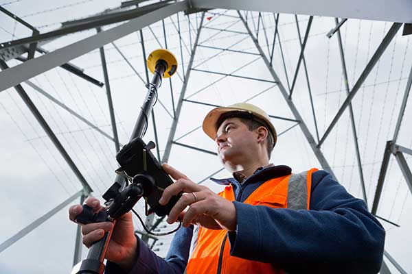
While rare, these tsunami earthquakes are particularly dangerous because they can hit coastal communities within five to 15 minutes, before officials can issue a warning. Now, however, using data from GPS receivers and seismographs near the 2010 Mentawai event, three seismologists — Valerie Sahakian and Diego Melgar at the University of Oregon and Muzli Muzli at the Earth Observatory of Singapore — may have found a way to identify tsunami earthquakes in time to warn people.
Very large earthquakes under an ocean break both the deeper part of a subduction zone, where one tectonic plate is sinking beneath another, as well as its shallow part, in a rapid motion that creates a tsunami. Tsunami earthquakes, on the other hand, happen almost entirely in the soft, weak section of a fault, moving slower and creating much more movement on or near the sea floor compared to earthquakes of the same size that happen in rigid rock. This creates much larger tsunamis than expected. A tsunami earthquake might have the same magnitude as an earthquake that occurs in rigid rock but produces much less of what seismologists call high-frequency energy.
Currently, officials issue tsunami warnings within tens of minutes of detecting an earthquake above a certain magnitude within a certain distance of a coastal area. This method, however, fails in the case of tsunami earthquakes, which produce tsunamis that are disproportionate to their magnitude.
Indian Ocean (Jan. 2, 2005): A village near the coast of Sumatra lays in ruin after a tsunami struck South East Asia. (Photo: U.S. Navy/Photographer’s Mate 2nd Class Philip A. McDaniel)
Traditionally, scientists have detected tsunami earthquakes by comparing their seismic magnitude with the amount of high-frequency energy they radiate, both recorded by distant stations. Tsunami earthquakes have a very low ratio of energy to magnitude; their energy, instead of strong shaking, produces a large slow movement of the seafloor.
In the past, scientists had to measure this ratio using seismic waves that had traveled from the earthquake’s epicenter to seismographs hundreds or thousands of miles away. This did not give them enough time to identify tsunami earthquakes and warn people before the tsunami’s wave hit the coast.
The recent analysis, however, enabled scientists to figure out a faster way to identify these rare tsunami earthquakes by using two proxies:
data from seismic stations onshore near the epicenters of 16 earthquakes that measured directly how much the ground shook in each case, to determine the amount of high frequency energy in each earthquake, and
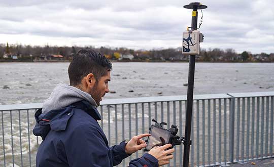
data from GPS stations close to the earthquakes, to measure the magnitude of each one on the basis of how much it moved the ground.
The GPS stations used in this study were from the Badan Informasi Geospasial (BIG) network from Indonesia. The data were acquired in real-time but processed with final orbits and clocks using precise point positioning (PPP). The scientists averaged the 3-component displacement, using centimeter-level solutions, and saw 3-10 centimeter vertical displacement.
This methodology, using data available during and immediately after an earthquake, enables scientists to compare the amount of energy in each earthquake with its magnitude, without waiting for their seismic waves to travel to distant measuring stations. Seismologists will be able to use this approach to identify tsunami earthquakes immediately and warn nearby coastal communities before a tsunami wave reaches them.
Citation. Sahakian, V. J., Melgar, D., & Muzli, M. (2019). “Weak near-field behavior of a tsunami earthquake: Toward real-time identification for local warning.” Geophysical Research Letters, 46(16), 9519–9528.
As we close the book on 2019 and head into the next decade, much has changed during the 2010s and the 21st century. This article will focus on the technological changes that made a significant impact on the surveying world, with the biggest advances being specifically GNSS-based improvements.
No, we will not debate the true beginning of a century (Jan. 1, 2000, versus Jan. 1, 2001), but instead look at the predicted issues with computers and the Y2K hysteria leading up to the end of 1999 as part of our nostalgic tour.
For the millennials and Gen-Z readers, bear with us old-timers for a few paragraphs while we take a trip down memory lane.
The tale of two centuries…
“It was the best of times, it was the worst of times, it was the age of wisdom, it was the age of foolishness, it was the epoch of belief, it was the epoch of incredulity, it was the season of Light, it was the season of Darkness, it was the spring of hope, it was the winter of despair, we had everything before us, we had nothing before us, we were all going direct to Heaven, we were all going direct the other way — in short, the period was so far like the present period, that some of its noisiest authorities insisted on its being received, for good or for evil, in the superlative degree of comparison only.”
In 1859, Charles Dickens wrote this opening paragraph for his well-known novel, “Tale of Two Cities,” to describe two environments (in this case being London versus Paris) at a significant transitional time. Such was the case for surveying and technology in the late 1990s with the rapid utilization of GNSS technology, expanded capability of robotic equipment and data collection. Some practitioners were excited about the new century while others yearned for bygone eras of less complicated procedures.
“Gonna party like it’s 1999…”
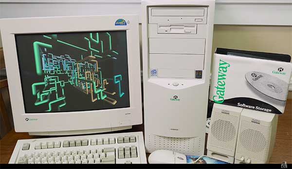
A 1999 Gateway PC refurbished by LRG. (Screenshot: LRG video, click to view)
With apologies to the late singer Prince and his 1982 hit song, the news surrounding the year 2000 was bleak when it came to computers and technology. For many of our readers, the technology available in 1999 might seem like the Stone Age. Most homes still used telephone land lines, “state of the art” cellphones were being produced by Nokia, personal computers (manufactured by Dell, Gateway, HP and IBM) were utilizing Pentium III processors (at a whopping 450 MHz!) with 5-10 GB storage. Internet Explorer was the web browser of choice, and Napster was gaining users exponentially sharing music downloads. Google was only one year old but rapidly replacing AltaVista and WebCrawler for our internet search engines. Life seemed good, but a storm was brewing…
The Y2K bug was front and center in all media outlets as many computerized systems were not programmed with the year 2000 in mind. This issue was unique in that it was a software and hardware problem to address. Replacement or patching of software, while taking a significant amount of time and money, can be much easier than computers and hardware loaded with chipsets that cannot be reprogrammed.
The Napster logo
Most system programming utilized a two-digit year designation instead of a four-digit version (99 versus 1999) and thus a date entry for January 1, 2000, normally composed as 1/1/00 in older systems would be recognized as January 1, 1900, instead. Because of this situation, many experts were predicting a global meltdown with government, utility company and banking disruptions that would render most computer systems unusable.
In the United States alone, over $100 billion was spent on computer upgrades and troubleshooting of the potential crisis. Thankfully, most of these systems had already been taken offline and replaced, but a few still lingered in critical systems. Because of pre-Y2K upgrade planning, many systems were tested and proven to be immune from the potential crash.
Specific Y2K issues that took place within the U.S. satellite system were isolated mostly to the units dedicated to surveillance, and not the navigation section used by surveyors. There was a small issue with the U.S. Naval Observatory, in which the date was deemed to be “Jan. 1, 19100” but that was rectified quickly.
The U.S. spy satellites, however, were knocked out by a faulty software patch rather than the original programming. These units were producing unusable information for three days before programmers were able to fix the problem. Imagine if that situation had happened to the navigational satellites and was impacting surveyors; we can only hope the GNSS system would have simply provided obvious bogus information.
Embracing RTK
By 1999, surveying had begun to embrace RTK systems for everyday measurement needs. Because of the constant focus of GPS technology moving forward, the operating systems for RTK were ahead of the curve for the Y2K issue. Fortunately, the navigational satellites as mentioned above did not fail with the date and time issues that were being predicted.
Logo of the now-defunct U.S. government Y2K website.
The Y2K bug did, however, affect a few users of older technology and software. Older data collectors, including ones based upon handheld calculators, were susceptible to date issues. Systems that were designed in the 1970s and ’80s should have been replaced with newer technology before 2000, but old surveyors stick to the adage: “If it isn’t broke, don’t fix it!”
For many, it wasn’t simply an upgrade in technology, but more of a radical change in known processes and procedures. New instruments and data collectors required new computers, which required new software, which required learning a completely new system.
Handheld GPS technology, introduced in the mid-1990s, was beginning to grow as the general public was embracing the new ability to determine geographical positions. While their use is quite simplified by today’s standards, nonetheless these devices captured the tech lover’s need for more accurate location determination.
In the end, Y2K wasn’t nearly the technological apocalypse many educated minds feared. While there were a few isolated incidents worldwide, everyday life went on without much of a blip on the radar. Planes didn’t fall out of the sky; financial systems didn’t come crashing down and life went on. Thankfully, surveyors everywhere went about their business on Monday, Jan. 3, 2000 as if nothing happened.
Then 20 years go by…
The new millennium has brought the surveying community many new exciting technologies and vast enhancements to age-old procedures. Field book notes has been mostly replaced with electronic data collectors, cellphone cameras and point clouds. Data is efficiently transferred between field and office with a remote connection and a blink of an eye. These past 20 years has seen a landslide of technological improvements, yet the future looks incredibly bright with more to come.
With the new year and decade, let’s look at where we are today and what advances we are anticipating:
GNSS CAPABILITY
GPS (Global Positioning System) began working in the U.S. in 1978 and as a true global system in 1994. This system was originally designed to work strictly for the United State military, but was discovered to have consumer applications shortly after implementation. There are currently 30 operational satellites in the GPS constellation with two (2) Block III versions being evaluated at press time. A total of ten (10) Block III satellites are planned to be operational by late 2023 or early 2024. These Block III versions will have an enhanced signal capability (L5 band) and will provide more accuracy and increased protection from jamming and spoofing.
GLONASS (GLObal NAvigation Satellite System) is the navigation system designed and implemented by Russia. This system was deemed operational in 1993 and currently has 28 operational satellites. Most surveying equipment in the United States has GLONASS tracking capability to greatly increase the accuracy and precision of most GNSS receivers.
China launched two more BeiDou satellites on Aug. 25, 2018. (Photo: CCTV)
Galileo is the satellite constellation system created by the European Union. It reached limited capability in 2016 with full expanded reach targeted for 2020. However, the reliability of the system is now in question as a total system outage occurred for seven days in July 2019. The satellites themselves were operational; it was the main control center that experienced the shutdown during a system maintenance upgrade. The overall integrity of the system has been restored and the planned rollout of full operational capability is still scheduled for 2020.
BeiDou, the national navigation system of China, has achieved 35 operational satellites with 13 additional vehicles currently being evaluated for implementation. With the increased number of satellites, many GNSS receiver manufacturers are including BeiDou as standard channel reception to greatly increase accuracy and precision for navigational purposes.
Two additional regional systems, QZSS (Quasi-Zenith Satellite System) from Japan and IRNSS (Indian Regional Navigation Satellite System) from India are currently working to install more satellites and provide navigation signals soon. Because these are regional systems, access to these signals for U.S.-based surveyors will not be available.
In 20 short years, we went from having two good systems to four very robust systems and two regional organizations.
While it is still unclear how political relationships will affect the ability to use a system from another country, the simple fact is that more vehicles in space will only increase the coverage, reliability and effectiveness of GNSS navigational data. Increased signal type and strength will also provide many benefits, so surveyors should look forward to even better GNSS days ahead.
ADDITIONAL CELLPHONE CAPABILITY
Several increases in cellphone technology will greatly enhance not only the consumer’s use of GNSS but the surveyor’s. This involves a two-step increase in value with the rollout of 5G signal technology and dual-frequency GNSS receiver hardware within the cellphone.
5G is being introduced in various markets around the country, but won’t see full potential until 2021 and beyond. Those who can use it in the short term will see greater bandwidth for data connectivity, but surveyors will start utilizing navigational enhancements because of the signal and transmitter technology.
Add to this mix the future implementation of dual-frequency GNSS chipsets to provide much more accurate location, and the surveyor will have more data-collection power in their pocket. Dual frequency was a gamechanger for GPS receivers in their infancy, so one can only imagine how much it will enhance the navigation accuracy when included in the cellphone.
REAL-TIME NETWORKS (GNSS)
Most urban and suburban surveyors already enjoy the benefit of a real-time network, either from a private or public system. With 5G and expanded use of more satellites and L5 signal, the RTN will become a better tool for surveyors everywhere. A reduction of setting up a base station increased productivity, less theft and less equipment costs. The RTN will become a standard operational tool just like having a total station in your survey rig.
DATA COLLECTORS
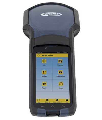
Photo: Spectra Geospatial
The technology hasn’t stopped with the unveiling of new data collectors and platforms. Small handheld devices used to rule the field surveyor’s world; now those devices have become bigger and more advanced than ever.
While most collectors already had touchscreens, the actual screen is increasing in size and functionality. Some are adopting the tablet-style format (8- and 10-inch screens), others are incorporating larger screens (7 inches) within the body of the traditional collector. All of them are including better cameras and enhanced connection capability through Wi-Fi, Bluetooth and cellular methods.
Also catching on is the use of bring-your-own-device (BYOD) with specialized apps for connecting to newer GNSS receivers. This allows surveyors to keep down costs of equipment by not having to purchase a dedicated data collector. As mentioned previously, once the cellphone becomes equipped with 5G and/or dual-frequency GNSS, it will become an excellent system for surveying that will produce extraordinary value for the surveyor.
SPATIAL DATA
The biggest revolution for surveyors in the coming years will be the ability to collect spatial data through a variety of equipment and sensors. Besides the obvious explosion of UAV capability, the small-format laser scanner is becoming user- and drafter-friendly as well as much more affordable. Now a surveyor can perform dozens (if not more) of small area scans with simplified orientation and scan formatting to create a great looking point cloud for data extraction and/or Building Information Modeling (BIM). Surveyors are beginning to understand how to utilize this technology and data to reach inaccessible areas and densified regions quickly. In addition to scanning technology, SLAM (simultaneous localization and mapping) will also become more mainstream as more surveyors are adopting the method for data collection.
What we’ve learned
“The days are long, but the years are short.” – Gretchen Rubin, author
Gretchen hit the nail on the head, as these past two decades have rolled on. When the end of 1999 was upon us, it seemed to be a big deal because of the potential of Y2K issues. There we were, surveyors with exciting technology in our hands, and now the forefathers of computers were going to erase it all due to not looking ahead to the next century.
We easily got past it, yet the memories of Y2K still linger on for some of us. The jump to 2010 didn’t foreshadow any drama (other than climbing out of a recession) and I personally didn’t think any different while moving the calendar to January 2020. But somehow in the last few months of 2019, there were many stories about the Y2K predicament, and it rekindled old memories of those weeks leading up to January 1, 2000.
Long story short, we survived and lived to survey many more days. Having time to look back and compare where we were 20 years ago to where we are now, I find it simply amazing. No, Rick Deckard isn’t flying by in his car catching bad guys (Blade Runner was set in 2019!), but surveying continues to amaze me with continued technological changes.
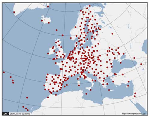
Belarus will soon be sharing GNSS data with the EUREF Permanent Network (EPN), the press service of the State Property Committee of Belarus told Belarus news agency BelTA.
Beginning March 1, the Belarusian state enterprise Belgeodeziya will start uploading data to two GNSS data processing centers. Until now, Belarus has been the only European country without a EUREF Permanent GNSS Network (EPN) station.
The EPN consists of
a network of continuously operating GNSS (GPS, GLONASS, Galileo, Beidou.) reference stations
data centers providing access to the station dat,
analysis centers that analyze the GNSS data
product centers or coordinators that generate the EPN products
a central bureau responsible for the daily monitoring and management of the EPN.
The EPN network is operated under the umbrella of the IAG (International Association of Geodesy) Regional Reference Frame sub-commission for Europe, EUREF.
Instructed by the State Property Committee, Belgeodeziya has added four Belarusian GNSS stations to the EPN, which unites more than 100 European agencies and universities.
Joining the network will provide Belarusian geodesists with direct access to international standards on the operation of permanent GNSS stations.
The Institute of Navigation (ION) has published its Global Navigation Satellite Systems (GNSS) Software Defined Radio Metadata Standard document.
According to ION, The standard is the product of a three-year long effort of the ION GNSS SDR Standard Working Group and defines parameters and schema to express the contents of SDR sample data files. The standard promotes the interoperability of GNSS SDR data collection systems and processors, ION added.
“In recent years there has been a proliferation of software defined radio data collection systems and processing platforms designed for Global Navigation Satellite System receiver applications or those that support GNSS bands,” ION said in a press release. “For post-processing, correctly interpreting the GNSS SDR sampled datasets produced or consumed by these systems has historically been a cumbersome and error-prone process. This is because these systems necessarily produce datasets of various formats, the subtleties of which are often lost in translation when communicating between the producer and consumer of these datasets. This specification standardizes the metadata associated with GNSS SDR sampled data files and the layout of the binary sample files.”
The new version of all-in-one MultiStation addresses a wide range of needs. (Photo: Leica Geosystems)
The new Nova MS60 MultiStation combines upgraded, faster 3D laser-scanning capabilities, GNSS connectivity and digital imaging with a high-end total station. According to Leica Geosystems, part of Hexagon, the multi-station brings sensor fusion to the “next level.”
The MS60 features several laser scanning updates, including an fast scanning speed of up to 30,000 points per second, optimized scan area definitions, adapted scan managements, and an improved scanning path for zenith scans.
It is also equipped with the unique AutoHeight feature, enabling users to save time by automatically measuring the instrument’s height with a simple button press. Measurement professionals can make decisions directly in the field, performing point-cloud analysis such as flatness analysis and as-built checks in the Inspect Surface app of the MS60.
“Scan data combined with traditionally measured points, whether it’s from the total stations or the GPS receivers, is one of those immediate deliverables that help our clients see what we’re doing. With the scan data of the Leica Nova MS60 MultiStation, we can graphically show — the same day it is collecting — the locations in the field to any person,” said Donald Smith, senior land surveyor and principal at BL Companies. “When you deliver on time and provide customers with a deliverable they can see, you’ve just got yourself a recurring client.”
The MS60 speeds up workflows by combining technologies in this all-in-one instrument. The MultiStation total station offers advanced imaging, scanning capabilities and GNSS connectivity. With Leica Captivate field software, all measurement and scanning data can be visualized in 3D for quality and completeness checks.
MS60 users can seamlessly transfer all data into Leica Infinity software to manage, process, analyze and perform a quality check. The MultiStation helps users deliver projects on time, save money and have high flexibility in the field.
“The MS60 merges data in a multi-level process — total station measurements are complemented by 3D point clouds, which are automatically registered and coloured by the image information. All data perfectly fits within the same coordinate system, globally referenced by GNSS measurements or by measuring known points,” said Falko Henning, senior product manager at Leica Geosystems.
“Unlike other measurement devices, the MS60 offers familiar total station capabilities and scanning functionality to fulfil job requirements on site.” Henning said. “The operator can use the red laser pointer to perform reflectorless measurements for direct remedial work on-site or stakeout points and use the field controller even while a scan is performed.”
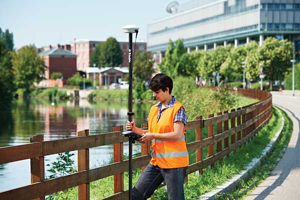
While often an underestimated component of a positioning and navigation system, a GNSS antenna is critical to a receiver’s success in acquiring all available GNSS signals while rejecting unintentional interference, jamming, multipath and spoofing. GNSS antennas come in as many flavors as receivers, to address the challenges posed by different market sectors, applications, environments and threats to signal integrity.
Each solution reflects a different balance among performance, cost, size and other variables. For example, antennas for handheld devices must be small and lightweight, while those for excavators and dozers can be much larger and heavier but must be able to operate for years while subjected to severe vibrations and harsh environmental conditions. Antennas for military and safety-critical applications must be especially impervious to jamming and spoofing.
Most applications, however, require antennas, like receivers, to have the smallest possible size, weight, power and cost (SWAP-C). Some applications, such as in the automotive market, must also take aesthetics into account.
We asked Javad GNSS, NovAtel, Trimble, Topcon and Harxon about their key markets and the challenges their antennas are designed to address. We also asked them to look back at the past three years and forward at the next three to discuss key innovations. Finally, they discuss technical challenges and industry trends.
See part 1 and part 2 of our GNSS receiver manufacturer overviews.
Javad GNSS
The GrAnt-G2T antenna. (Photo: Javad GNSS)
Key Markets. “The unmistakable lime-green Javad GNSS receivers and antennas are known to surveyors the world over, and we also support reference station, machine control, precise timing and any other market requiring high-performance / high-precision GNSS antennas,” said Javad Ashjaee, founder and CEO.
Specific Challenges. “A good GNSS receiver should bring in all wideband GNSS signals and reject all other unwanted signals,” Ashjaee said. “J-Shield, a robust filter in our antennas, blocks out-of-band interference — in particular, signals near the GNSS bands, such as the LightSquared signals — making the precious near-band spectrum available for other usages.”
Key Innovations. “To support our users in ever more challenging environments,” Ashjaee said, “such as denied environments where electronic warfare takes place, we have developed a new GrAnt-G2T antenna variant with even stronger J-Shield filtering: improved P1dB (the 1-dB compression point, > –30 dBm) and additional upper and lower out-of-band filtering.”
Harxon
The HX-CSX100. (Photo: Harxon)
Key Markets.Harxon is dedicated to designing and manufacturing high-precision GNSS antennas and solutions for industries such as surveying, UAVs and precision agriculture, said Wang Xiaohui, R&D manager.
Specific Challenges. “Harxon’s GNSS antennas primarily address issues related to the reliability of phase center, multi-constellation full-frequency coverage,” Xiaohui said, “tracing unstable satellite signals at low elevations, multipath signal interference, and how to integrate high-precision GNSS antennas and mobile communication antennas into a single design.”
Key Innovations. Over the past three years, Harxon has made “great breakthroughs” in GNSS antenna innovation, Xiaohui said. First, it greatly reduced the size and weight of choke ring antennas. As an example, Xiaohui cited the company’s mini choke ring antenna HX-CGX611A. Second, it optimized accuracy to the millimeter level and expanded to full frequency its quadrifilar helix antenna, such as with the D-Helix antenna. Third, Harxon upgraded the surveying industry to 4G communication by developing a four-in-one antenna that supports multi-constellation with full frequencies and integrates GNSS antennas, Bluetooth and 4G modules with high compatibility and outstanding performance, Xiaohui said, such as with the HX-CSX100. “For the next three years, Harxon will continue its research and investment in antenna technology breakthroughs, especially with regard to further miniaturization and improved performance.”
Technical Challenges. “The first interesting challenge is how to guarantee the performance of the antenna while miniaturizing it per our customers’ demands,” Xiaohui said. The second is reducing the size and weight of antennas with anti-multipath technology, “so as to boost the applications of high-precision positioning GNSS technology.”
Trimble
An external Trimble antenna helps the GeoXR handheld achieve survey-grade accuracy. (Photo: Trimble)
Key Markets. “Trimble’s core technologies in positioning, modeling, connectivity and data analytics enable customers to improve productivity, quality, safety and sustainability,” said Stuart Riley, vice president, GNSS Technology. “From purpose-built products to enterprise lifecycle solutions, Trimble software, hardware and services are transforming industries such as agriculture, construction, geospatial, transportation and logistics, rail, forestry, utilities and autonomous applications.”
Specific Challenges. Each application has different requirements, Riley said. “For applications that require the highest position accuracy, the stability of the phase center, multipath mitigation, and the unit-to-unit production consistency are critical,” he said. Some customers require high performance in challenging environments — such as the high vibration experienced on construction equipment — while others require smaller, lower-cost antennas and can tolerate a slight reduction in accuracy. “The antenna is typically a combination of a passive antenna element with an active low noise amplifier (LNA),” he said. “The LNA needs to be carefully designed to remain linear in the presence of in-band jamming while rejecting out-of-band signals. There are size and cost trade-off challenges to the filter roll-off at the band edge that need to be managed.”
Key Innovations. For high-precision applications, Trimble first released the Zephyr series of antennas in the late 1990s. “It provides excellent phase center stability and unit-to-unit production repeatability, and has exceptional multipath mitigation performance, which is enhanced in the geodetic version,” Riley said. Since first introducing the antenna, Trimble has added support for additional GNSS systems and RF bands (L1/E1, L2, L5/E5 and L6/E6), transitioned to a RoHS-compliant manufacturing process, improved the LNA performance, developed rugged versions for construction vehicle mounting, and produced a smaller version used in the Trimble R10, R12 and SPS986 GNSS receivers.
“More recently,” Riley said, “we developed a lower-cost high-performance antenna for the Trimble Catalyst software-defined GNSS receiver for Android phones and tablets, as well as an antenna in the Nav-900 guidance controller for agriculture that implements a metamaterial design. Looking forward, we expect to continue to innovate by providing antennas that meet the needs of the different markets we serve. Each application has unique requirements, which require us to balance the cost, performance and size to develop the appropriately optimized product. Enhancements will include novel antenna architectures, production technique improvements, and careful material selection.”
Technical Challenges. Trimble users have a wide variety of requirements, Riley said. “The challenges come in balancing the seemingly conflicting needs for performance, size, weight and cost. Because Trimble focuses on specific user segments, we can provide antenna solutions that are the best fit for the various applications. For example, an antenna in a handheld device must be small and lightweight; however, on a construction machine, durability takes precedence over size and weight.”
Topcon Positioning Group
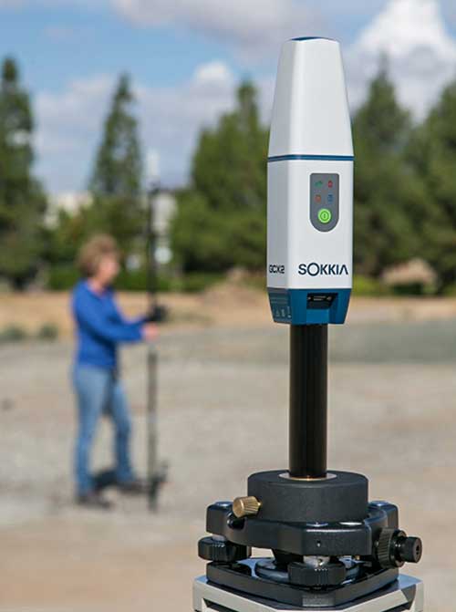
The Sokkia GCX2 receiver integrates a helical antenna. (Photo: Topcon)
Key Markets.Topcon Positioning Group is a leading designer, manufacturer and distributor of precision measurement and workflow solutions for the global construction, geospatial and agricultural markets, according to Alok Srivastava, director, product management. “By integrating high-precision measurement technology, software, services and data, Topcon has a vision to improve productivity to meet global demand for sustainable infrastructure and agriculture,” Srivastava said.
Specific Challenges. The physical challenges when designing an antenna for geomatics applications have been multipath and interference mitigation, Srivastava explained. “Topcon has an advanced research and development team that focuses solely on antenna designs. The team dedicates its efforts to providing state-of-the-art antennas for all positioning needs.”
Key Innovations. “Topcon was very early in realizing the growing needs for radio spectrum and the challenges it may bring to GNSS technology,” Srivastava said. “It has innovated and used filters to mitigate interference from Japan LTE signals for a long time.”
Topcon’s antenna team is “among the most innovative in the industry,” Srivastava said, and “has brought many unique designs of antennas over the years. The antenna is a key element of an integrated receiver in dictating the design of the whole receiver.” With the release of the Sokkia GCX2 receiver, he explained, his company introduced to the industry the integration of a helical antenna into a high-performing integrated receiver.
Its infrastructure antennas, the CR-G5 and PN-A5, are available with options including cavity filter technology. “The cavity filter has the superior ability to minimize near-band interference,” Srivastava said. Topcon’s antenna farm at the Concordia test site in Italy contains an absolute calibration robot, a large format antenna (BigAnt) for a high-quality geodetic ground station, and patented technology for controlled testing of GNSS technology in artificial obstructions.
“Vibration mitigation is the key when an antenna is mounted to a piece of machinery,” Srivastava said. “Topcon antennas are an integral component of our Quartz Lock Loop (QLL) technology for robust GNSS operation in high-vibration environments.”
Technical Challenges. The importance of antennas can be underestimated, Srivastava pointed out, especially with rapidly growing interest in GNSS technology in consumer applications. “The antenna is one of the most critical technologies when it comes to reliable and robust GNSS positioning. Designers and manufacturers of antenna technology with years of experience understand the seriousness of this task, and are fully equipped to deliver results without compromising quality and performance.”
NovAtel
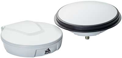
The VEXXIS family of GNSS antennas. (Photo: NovAtel)
Key Markets. Key antenna markets for Hexagon’s Autonomy & Positioning division are split into three areas, according to Dean Foster, director of hardware engineering. His area includes the company’s anti-jamming antenna technology (GAJT) and robust SWAP-C antennas. The other two are precision and SMART antennas for agriculture, mining, survey and autonomous vehicles (Vexxis, SMART7, and GNSS 1500), and reference GNSS antennas (GNSS750 and ANT-C2GA).
Specific Challenges.NovAtel’s antennas address three main challenges. First, jamming and interference, whether intentional or unintentional, are becoming increasingly commonplace and seriously impact GNSS reception. “These issues are addressed by our GAJT product line of high-precision anti-jamming antennas, which can mitigate multiple jammers simultaneously,” Foster said. Second, “the stability and precision of the antenna’s phase center is critical to deliver robust and precise GNSS position even in challenging environments, which is addressed by our Vexxis GNSS-800 antennas.” Finally, more frequent use of GNSS in environments with reflection issues is making multipath rejection critical. “The entire line of NovAtel antennas, including Vexxis, SMART and GAJT, ensures use of the most direct signals.”
Key Innovations. Driverless vehicles require sub-meter-level positioning for lane-level resolution. “Multi-constellation/multi-frequency GNSS with protection limits and correction services are necessary to move forward safely,” Foster said. “This technology does not work with the smallest size, single-frequency, narrow-band antennas that cars currently utilize, so we’re building on our deep experience and knowledge to develop production-grade automotive antenna technologies.” An emerging requirement is reducing size, weight, power and cost (SWAP-C). “In the defense market, we first offered jamming and interference mitigation with the GAJT-710, which progressed to the GAJT-AE, and most recently we launched the GAJT-410.”
Technical Challenges. All markets want the smallest, most robust and cost-effective antenna to meet their needs, Foster said, adding that NovAtel is helping customers work through how to select, place and integrate antennas into their platforms to address real-world problems.
The prevalence of intentional and unintentional GNSS interference has sparked quick evolution in antenna technology, including the emergence of breakthrough technology in 2019 and new advancements in development, said Imtiaz Bahadur, product line manager.
Specifically, the drive to advance antenna technology is due to “an increased demand for broader coverage, stringent industry compliance, and a need for robust capabilities.”
Key Innovations. Among recent innovations in antenna technology, Bahadur cited GPS antennas with support for dual-frequency multi-constellation compliance with Global Aircraft Traffic Management (GATM) mandates to enable military aircraft to operate in controlled airspace, and antennas that offer broader band coverage.
In 2019, Cobham introduced the 20-2041 Fixed Reception Pattern Array (FRPA) GPS antenna, which addresses all three of these priorities, said Darren Windust, product manager – air. The L1/L2 dual-frequency GPS antenna is certified to both ETSO-C190 and MSO-C144. “In conjunction with a certified receiver, the 20-2041 offers a single solution to comply with GATM regulations to access controlled airspace and undertake GPS precision approach and landings, in a standard 3.5-inch form factor.”
Technical Challenges. “It’s clear that moving from one GPS signal to eight signals from four constellations in support of performance-based navigation is going to be the next major disruptor because of the significantly expanded signal power and highly efficient design,” Bahadur said. The quest to make antennas smaller also continues. “Today, there are physical limitations on how far one can miniaturize the antenna while ensuring sufficient gain is received. Research and development efforts are underway to build ‘smart antenna’ concepts for the future. Moving into the next few years, robust antenna capabilities will arrive in smaller, more efficient form factors.”
In the second part of our receiver feature, top receiver manufacturers discuss what’s on the horizon for GNSS receivers: recent and upcoming innovations, combating spoofing and jamming, fusing GNSS with other sensors, and the impact of increasing accuracy both for professional surveyors and consumers.
In January, we featured responses from NovAtel, Trimble, Unicore, Topcon, Hemisphere GNSS, CNC Navigation and Septentrio to questions about their recent and upcoming innovations in the design and manufacturing of GNSS receivers. We continue in this issue with responses to the same questions from Javad GNSS, Swift Navigation, Eos Positioning Systems, Tersus GNSS, TeleOrbit, Allystar Technology and NTLab.
All GNSS receiver manufacturers agree that spoofing and intentional and unintentional jamming are serious challenges. Their approaches to dealing with these challenges differ, however, as they rely on different combinations of technologies on both their receivers (such as monitoring cycle slips and using analog-to-digital converters, correlators and notch filters) and their antennas (such as using array antennas), as well as the new Galileo authentication service.
Photo: Tersus GNSS
Many receiver manufacturers now routinely use optical, inertial and other sensors — which continue to drop in price and increase in performance — to supplement GNSS signals where they are degraded or denied, especially in the automotive market.
Carrier phase positioning and correction services are increasingly improving the accuracy of survey stations and reducing their price. Meanwhile, submeter accuracy is spreading beyond surveying to other industries. Performance in challenging conditions also continues to improve, thanks largely to the increase in the number of GNSS constellations, available satellites and frequencies. (For a review of recent developments in antennas, see our companion article here.)
On the consumer side, the introduction of multi-frequency GNSS receiver chips, the increased use of correction services, and, in a few countries, the deployment of thousands of additional base stations will continue to increase the location accuracy of cell phones and other consumer devices, enabling new applications. However, in these devices size and cost limitations make antenna performance particularly challenging. (See Part 1 here.)
Javad GNSS
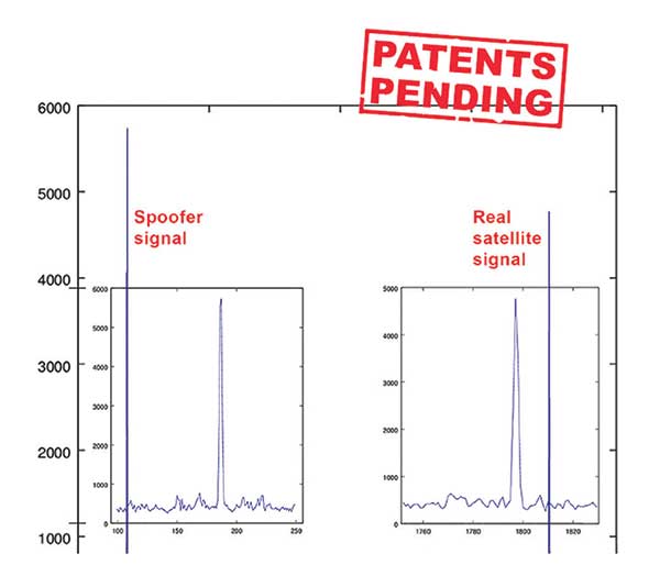
Jamming and Spoofing. “We protect you against jammers and spoofers like no one else can,” said Javad Ashjaee, founder and CEO of Javad GNSS. “We use multiple techniques to detect spoofers, the most important being the use of digital signal processing to detect more than one peak. First, with 864 channels and about 130,000 Quick Acquisition Channels in our Triumph chip, we have resources to assign more than one channel to each satellite to find all signals that are transmitted with that GNSS PRN code. If we detect more than one reasonable and consistent correlation peak for any PRN code, we know that we are being spoofed and can then identify the spoofer signals and ignore the wrong peak.”
An example of two peaks. (Chart: Javad GNSS)
Ashjaee described additional techniques:
The J-Shield filter blocks out-of-band interference.
Sixteen 255th-order FIR anti-jam digital filters protect against static in-band interference, and 16 adaptive 80th-order digital filters protect against dynamic interference.
Javad products measure the level of interference as a percentage of in-band noise above normal.
The Triumph chip has a powerful spectrum analyzer. Each spectrum shows the power and the shape of the interfering signals and jammers. This is more powerful and more efficient than using a commercial spectrum analyzer to evaluate the environment.
The chip also keeps a record of Automatic Gain Control, which is another indicator of external signals. A change in AGC can indicate interference.
Deviation of SNR from the expected value is another important indicator of interference.
“Usually there are over 100 signals available at any given time, and we need only four good signals to compute position. It is extremely unlikely that we can be spoofed without our knowledge.” Ashjaee concluded. “We will immediately recognize and take corrective actions.”
Jamming and spoofing protection is available on all Javad GNSS receivers and OEM boards. Read more about Javad GNSS’s jamming and spoofing protection in the December 2019 issue.
Sensor Fusion. “To support users in environments where GNSS RTK solutions are difficult or impossible to obtain,” Ashjaee said, “Javad GNSS has invented the J-Mate, which is a remotely controlled robotic EDM device and digital camera. GNSS RTK and optical can be seamlessly integrated using the J-Mate as the seventh RTK engine. Just set up a Triumph-3 on top of a J-Mate and a Triumph LS on top of a zebra rod, making the former pair the RTK base station and the latter pair the RTK rover.” Read more about Javad GNSS’s RTK and Optical United solution in the November 2019 issue.
Swift Navigation
Jamming and Spoofing. “Receivers have become more robust to intentional jamming by mimicking the jammers’ behavior to cancel it,” said Alex Pun, staff product manager for Swift. “Nevertheless, advanced jamming and spoofing mitigation often imply array antennas. A real evolution lies in considering these threats only in terms of the availability of the GNSS sensor, now part of a complete multi-sensor positioning engine such as Starling.”
Sensor Fusion. IMUs, visual sensors and GNSS will aid each other in different types of environments and scenarios, explained Pun. “Sensors are becoming more affordable, and their performance increases with each new generation. Sensor fusion will be the glue that will bind them to provide a precise positioning solution.”
Surveying. The combined use of carrier-phase positioning and correction services, such as Swift’s Skylark, will greatly improve accuracy and reduce the cost of survey stations, because they make their accuracy less dependent on the intrinsic performance of the receiver and the antenna, Pun said. “A global service eliminates the need for an individual base station.”
Consumer Devices. “The introduction of dual-frequency GNSS receivers from chip manufacturers will help improve positioning in cell phones and other consumer devices,” Pun said. “These chips, coupled with a widely available correction service such as Skylark, will greatly improve their performance accuracy to sub-meter levels.”
Other Challenges. Performance stability of the antenna and its characterization will become the main challenge to exploiting the new GNSS ASICs (application-specific integrated circuits) and correction services at their highest level of performance, Pun said. “A positioning engine can exploit this information to accelerate the convergence to the high-accuracy solution, and then improve its availability.”
Eos Positioning Systems
A surveyor uses the Arrow Gold receiver to map assets in Terrebonne, Quebec, Canada. (Photo: Eos Positioning)
“The past three years have seen considerable innovations and trends in the GNSS industry,” said Jean-Yves Lauture, CTO of Eos Positioning. “Receivers are becoming increasingly affordable and the adoption of higher-accuracy (submeter, centimeter) positioning by other industries, outside of conventional surveying, is growing. Considering the now four usable GNSS constellations and the aggressive launches of Galileo and BeiDou satellites, the number of available satellites and the list of frequencies they use has considerably increased.
“Although accuracy itself is not really improving, performance is — particularly in tougher conditions. It’s not uncommon for customers to use 30 to 35 satellites out of more than 40 in view using an Arrow Series GNSS receiver. The numbers are even higher in the Pacific regions, thanks to geostationary BeiDou satellites. This is, by far, more than double the number of satellites available with just GPS and GLONASS.”
Consumer Devices. “It will be challenging for smartphones and consumer devices to achieve survey-grade accuracy in the next few years. They face certain limitations. For instance, there is a cost and physical size associated with using a high-end GNSS antenna with a minimum of ground plane to achieve these levels of accuracy.
The Arrow Gold RTK GNSS receiver. (Photo: Eos Positioning)
“Also, it is unlikely that the manufacturers of consumer devices will invest in developing the advanced algorithms needed for a high level of constant accuracy and performance. In order to fit into a smartphone, consumer-grade GNSS chipset manufacturers must drop the use of many available signals and frequencies to keep both size and power consumption to a minimum.”
Allystar Technology
Photo: Allystar
Jamming and Spoofing. The GNSS chip in Allystar’s TAU1301 module supports eight adaptive notch filters to reduce the effects of GNSS jamming, explained Shi-Xian Yang, senior principal engineer in the company’s Baseband Algorithm Department. “It significantly improves the performance of GNSS tracking measurements, even in the presence of strong and fast-varying jamming signals.”
Sensor Fusion. The TAU1310 integrates a six-axis micro-electromechanical system (MEMS) gyro, which makes its affordable for the mass market, Yang said.
The Lenovo Z6. (Photo: Lenovo)
Consumer Devices. In its Z6 smartphone, Lenovo has taken advantage of the great improvement in multipath mitigation provided by the L5 signal’s higher chip rate and the output of high quality raw data via the TAU1302’s HD8040 GNSS chipset to improve the accuracy experience in the consumer market, Yang explained. Additionally, he pointed out, cell phones and other consumer devices now enable developers to access the raw sensor data from such sensors as accelerometers and barometers to input into their fusion algorithms.
Other Challenges. In the future, the TAU1310 could also support the L6 signal for PPP-RTK application.
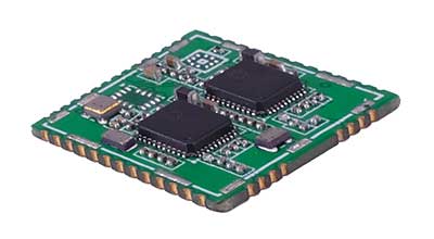
NTLab
NTLab anti-jamming GNSS receiver. (Photo: NTLab)
Jamming and Spoofing. The problem of jamming and spoofing worries customers, according to Konstantin Yuriev, lead GNSS engineer at NTLab. The combination of anti-jam and anti-spoofing is in greater demand because the anti-jam feature alone is becoming insufficient. Yuriev cited the European Union’s new requirements for the European Railway Traffic Management System (ERTMS), which makes anti-spoofing mandatory.
The key issue today is “the solution to the problem of reducing the size and cost of anti-jam receivers, so that they become available to consumers on the civilian market. The key technology for this will be increasing the degree of integration of the component base, first creating a chipset for solving anti-jamming and anti-spoofing tasks, and then moving on to a single-chip solution. We have created a chipset and are ready to start work on the further integration into a single chip.”
Sensor Fusion. The traditional task of integrating data from a GPS antenna and a MEMS sensor has been solved, Yuriev said, with many such solutions on the market. One task is to track the antenna’s tilt. “The antenna, GNSS receiver, and MEMS sensors should be located very closely to each other — if possible, on a single small board,” Yuriev said. “Here, again, the solution is to increase the degree of integration, up to placing the baseband processor on the same chip with the digital CMOS circuitry of the MEMS sensor.” Another application of MEMS is serving as the core of an inertial navigation system (INS), providing an auxiliary subsystem for detecting the presence of spoofing. “This is more of an algorithmic task,” Yuriev said, “because traditional coupling using recursive filters is not enough. It is necessary to ensure the independence of the INS subsystem from the GNSS solution, or their intelligent mutual cross-control.”
Surveying. A major part of the cost of a survey-grade device, Yuriev pointed out, is for additional services, know-how, and other added values. There is market demand for a business model in which device price could go down while maintaining the main values for the customer. “This could be achieved if end-users tightly cooperate with hardware manufacturers, skipping third-party integrators. Alternatively, multiple third parties could compete, keeping the cost of the software low. One of the technical solutions for this is to provide software application programming interfaces (APIs) that will allow multiple third parties to offer application-level software for the same hardware. We call it the ‘open platform’ approach. One of our products implements this strategy.”
Other Challenges. Despite some skeptics, Yuriev argued, new GNSS systems have been successful. “A good example is IRNSS (NavIC), with India’s population of 1.3 billion forming a potential market. Moreover, according to our studies, good coverage is provided not only in India’s territory. We are working on creating an economically affordable solution with support for the NavIC S-band. A new chip-scale packaged RFIC (radio-frequency integrated circuit) should minimize the size, consumption, and price of NavIC-oriented modules, while maintaining all the advantages of the S-band signal in areas close to the equator. This is our solution to the problem.”
TeleOrbit
GOOSE platform. (Photo: Fraunhofer IIS)
GNSS Receiver Development Platform. The company’s GOOSE platform is a field-programmable gate array (FPGA)-based GNSS receiver, developed by Fraunhofer IIS, making it flexible in processing new or proprietary signals, according to Katrin Dietmayer, software development engineer at Fraunhofer IIS. “It comprises 60 hardware channels in real time and provides an open software interface for customer applications,” she explained.
Jamming and Spoofing. “It grants deep access to the hardware interface, down to, for example, the correlation values. Additionally, anti-jamming functions (such as notch-filter or pulse-blanker) can be added and anti-spoofing algorithms are already implemented. Thanks to the open architecture, our customers can also implement these or other algorithms.”
Sensor Fusion. Vector tracking in real time is already implemented on code base. Deep coupling with INS/IMU multi-sensor fusion — for example, with an odometer, ultra wideband or 5G — are possible and under development, Dietmayer said.
Surveying.TeleOrbit provides GNSS-RTK using RTKLIB. “The implemented Open GNSS Receiver Protocol (OGRP) is fully documented with a parsing tool using CONVBIN from RTKLIB as RINEX converter,” Dietmayer explained.
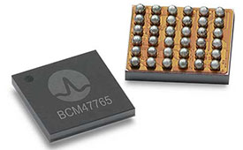
Consumer Devices. GOOSE is also used as the reference receiver in the ESA project Receiver Technologies for Future Mass Market (RT4FMM) devices. The project validates state-of-the-art dual-frequency mass-market receivers based on Broadcom BCM47755 and u-blox F9 and compares their performance against GOOSE E5AltBOC processing.
Other Challenges. GOOSE already processes the new Galileo OS-NMA (Open Service – Navigation Messages Authentication), while implementing the new Galileo High Accuracy Service (HAS) is on the roadmap. “The combination of these new features will result in a robust and reliable high-accuracy position,” Dietmayer said. “For system testing, the intermediate frequency signals can be recorded, processed and replayed with the platform.”
Tersus GNSS
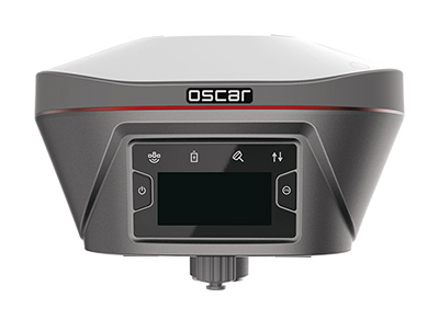
The Oscar. (Photo: Tersus GNSS)
Jamming and Spoofing. Xiaohua Wen, founder and CEO, said his company has done much research and testing on jamming and spoofing. “We already implemented a high dynamic analog-to-digital converter to overcome jamming. To mitigate spoofing, we think that internet of things (IoT) devices can leverage cloud services. Alternatively, the new Galileo authentication service may serve the same function.”
Sensor Fusion.Tersus GNSS makes an INS product, and its Oscar receiver contains an inertial measurement unit (IMU). “The sensor fusion hub is a very hot topic in the automobile industry,” Wen said. “We are quickly adapting our Oscar and INS product line for the creation of high definition maps and for indoor navigation. We think it’s still the major pain point for a crowded country such as China.”
Surveying. As has been the case in many other industries, Wen said, the widespread adoption of GNSS technology and the increase in the number of players in the field has led to a drop in prices. “Tersus’ David and Oscar models are low cost but still perform well compared with Tier 1 players for professional survey machines using our own OEM GNSS board,” he said.
Consumer Devices. The fact that a few vendors are providing dual-frequency chipsets in smartphones opens the door for consumer-grade sub-decimeter applications, Wen said. “But we think the antenna could be a big challenge for the small devices.”
Other Challenges. “Mobile carriers are building thousands of base stations,” Wen said. “For example, Softbank in Japan completed 3,300 stations this year. China Mobile just issued a bid for a phase one project for 4,400 stations. We think mobile phone innovations for the new high-accuracy application may have some impacts in the coming years. We have been actively looking at some new GIS (geographic information systems) applications based on our in-house Nuwa platform.”
My last column, December 2019, highlighted the National Geodetic Survey’s (NGS) new Geoid Monitoring Service (GeMS); and, that NGS’ will be publishing a gridded geoid model GEOID2022 that will contain two components: (1) Static Geoid model of 2022 (SGEOID2022) and (2) Dynamic Geoid model of 2022 (DGEOID2022). That’s what going to happen in 2022, but what about today? Since GEOID18 has been officially released for public use, it’s time to look at differences between the Geoid18 published value and estimated geoid values computed using information from NGS’ datasheet. This column will provide an analysis of the differences between the latest published hybrid Geoid18 values provided on NGS’ Datasheet and the computed geoid height value using the published NAD 83 (2011) ellipsoid height and NAVD 88 orthometric height. This is what a user will see if they computed differences using NGS’ datasheets published values. The question will always be asked, why is there a difference between the published Geoid18 value and the computed geoid value. This column will explain some reasons for the differences.
It’s mostly good news but there are some issues that should be highlighted. This column will highlight issues on differences due to published heights that have changed since the database pull for Geoid18.
First, it should be noted that NGS’ hybrid geoid models are different than NGS’ experimental gravimetric geoid models. My December 2018 column explains these differences.
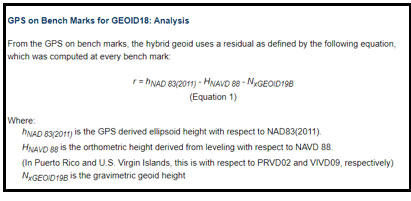
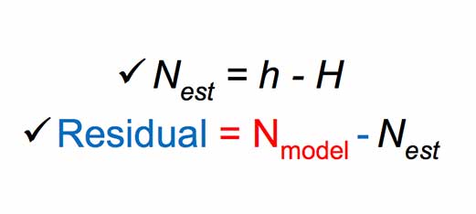
I would like to emphasize that, in my opinion, hybrid geoid models should be denoted as transformation models. Saying that, hybrid geoid models are related to “real” geoid models. Hybrid geoid model GEOID18 was computed based on NGS’ gravimetric geoid model xGeoid19b; therefore, GEOID18 is related to a gravimetric geoid model but its function is to estimate GNSS-derived orthometric heights consistent with NAVD 88 heights. As described in my previous columns, the GPS on Bench Marks (GPSBMs) data provide an estimate of the geoid height ‘N’ by differencing the ellipsoidal height ‘h’ from the orthometric height ‘H’: (N = h – H). These differences are then compared to the gravimetrically-derived geoid model. The box titled “Excerpt from Geoid18 Website Technical Details” provides a summary of the process from NGS Geoid18 web page technical details document.
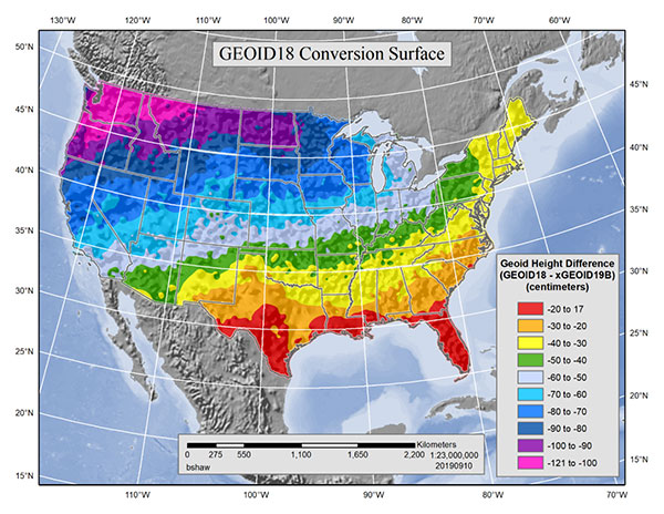
The figure in the box titled “GEOID18 Conversion Surface in cm” is the surface that represents the difference between NAVD 88 as a datum and the geopotential (geoid) surface used in the gravimetric geoid. This is the difference between the hybrid geoid and the gravimetric geoid with respect to NAD83 (GEOID18 – xGEOID19B). This surface has three essential components: a bias, a continental tilt, and local warping from the bench marks.
Hybrid Geoid Model Construction
The residuals obtained in equation 1 are contaminated with a continential tilt and bias that is estimated and removed with a simple two-dimensional planar surface. The bias-free and tilt-free residuals are ultimately used to determine a mathematical model using least squares collocation (LSC) and multiple Gaussian functions to describe the behavior seen at the bench marks. Once the relationship between the points is modeled, the model is used to generate a 1 arcminute regular grid for interpolation purposes. Figure 2 shows the final conversion surface. This surface represents the difference between NAVD 88 as a datum and the geopotential (geoid) surface used in the gravimetric geoid. This is the difference between the hybrid geoid and the gravimetric geoid with respect to NAD83 (GEOID18 – xGEOID19B). This surface has three essential components: a bias, a continental tilt, and local warping from the bench marks.
GEOID18 Conversion Surface in cm
Image: National Geodetic Survey
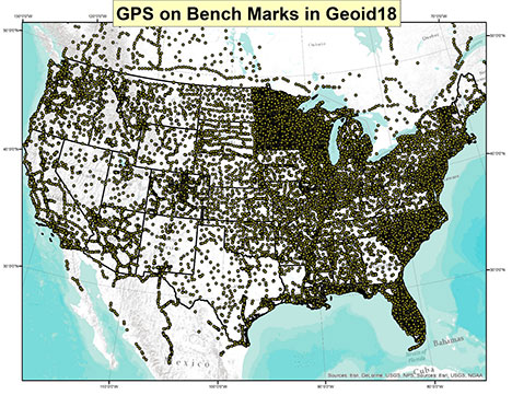
Looking at the figure in the box, the bias and tilt between the hybrid geoid model (Geoid18) and the experimental gravimetric geoid model (xGeoid19b) are fairly obvious. It’s the local warping from the bench mark data that may cause some issues to surveyors or, at least at a minimum, raise some concerned by surveyors. The box titled “Plot of the GPS on Bench Marks Involved in Geoid18” provides a plot of the GPS on Bench Marks (GPSBMs) used in the generation of Geoid18. Users can download the list of GPSBMs stations from the NGS Geoid18 website. There were 32,357 stations used to generate the model. This was an increase of approximately 6,800 stations (26%) over the hybrid geoid model Geoid12B.
Plot of the GPS on Bench Marks Involved in Geoid18
Image: National Geodetic Survey
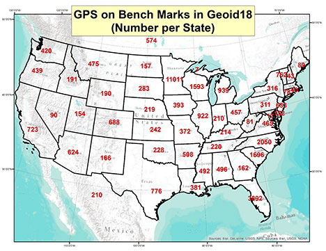
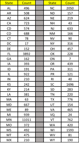
The boxes titled “Number of GPS on Bench Mark Stations by State” and “Number of GPS on Bench Mark Stations by State in Northeast U.S.” provide the number of data points per state.
Number of GPS on Bench Mark Stations by State
Image: National Geodetic Survey
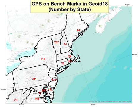
Number of GPS on Bench Mark Stations by State in Northeast U.S.
Image: National Geodetic Survey
The box titled “Table of Number of Data Points per State” provides the number of stations per State in tabular form.
Table of Number of Data Points per State
Data: National Geodetic Survey
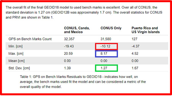
The box titled “Summary of Overall fit of Geoid18” provides a summary of the fit of residuals of Geoid18 from the NGS GEOID18 technical details document. Looking at the CONUS overall values, the standard deviation is very low 1.27 cm which is a little better than Geoid12B (1.7 cm). It should be noted that there are some large outliers (minimum value of -10.12 cm and maximum value of 8.17 cm).
For this column, the file of bench marks provided on the NGS Geoid18 web page were combined with the published ellipsoid, orthometric, and Geoid18 heights from NGS’ datasheet. The difference between the published geoid height (Geoid18) and the estimated geoid height [published NAD 83 (2011) ellipsoid height minus NAVD 88 orthometric height] was computed using the following formula:
Data: National Geodetic Survey
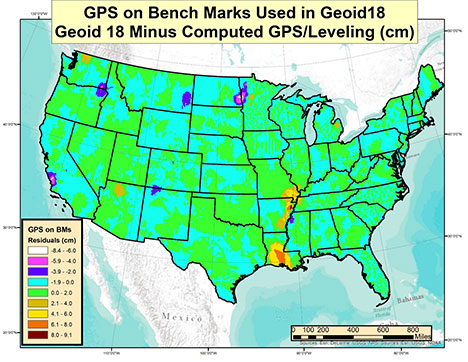
The box titled “Plot of Differences Based on GPS on Bench Marks Used in Geoid18” depicts these differences based on the stations used to generate Geoid18.
Plot of Differences Based on GPS on Bench Marks Used in Geoid18
Image: National Geodetic Survey
Most of the values depicted on the plot are within the +/- 2 cm which is what you’d expect because the standard deviation of the overall fit is 1.4 cm. One to two centimeters is a very reasonable difference between the modeled and computed values. The question someone may ask is, I thought the model should be good to 1.4 cm so why are there large residual values on the map? There are several reasons why some of these differences are large but each case needs to be investigated to determine why they are large. This column will address one region as an example and provide a method for others to investigate differences in their area of interest.
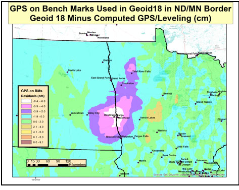
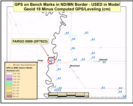
The box titled “Plot of GPS on Bench Mark Differences at the ND/MN Border” depicts a very large difference between the modeled geoid model and the estimated geoid height along the ND/MN border. As indicated in the box, the difference exceeds 6 cm.
Plot of GPS on Bench Mark Differences at the ND/MN Border
Image: National Geodetic Survey
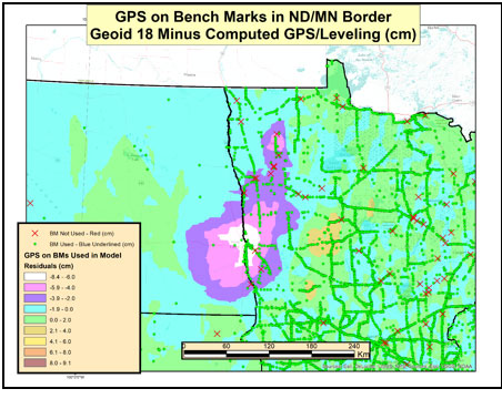
The box titled “Plot of GPS on Bench Mark Stations in the ND/MN Border Region” depict the bench marks involved in the development of Geoid18. The green circles represent the GPSBMs stations used in the creation of Geoid18 and the red “x” denote the stations that were not used in the creation of the model. As indicated in the plot, there were a lot of GPSBMs stations in the State of Minnesota (11,011).
Plot of GPS on Bench Mark Stations in the ND/MN Border Region
Image: National Geodetic Survey
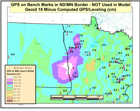
The box titled “Differences on GPS on Bench Marks in ND/MN Border — NOT Used in Model” depict the values of the rejected GPS on BMs stations. These stations were not used to create the hybrid geoid model Geoid18. As the plot indicates there are several large differences. This is not really surprising since these stations were not used in the model.
Differences on GPS on Bench Marks in ND/MN Border — NOT Used in Model
Image: National Geodetic Survey
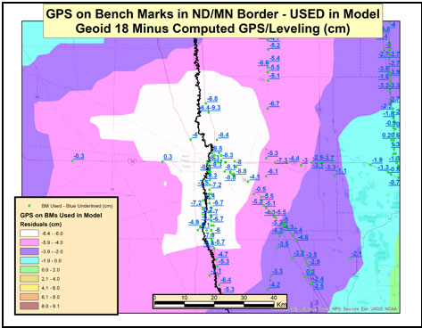
The box titled “Differences on GPS on Bench Marks in ND/MN Border — USED in Model” depict the values of the GPS on BMs stations used to create the Geoid18 model. Some of these differences exceed 8 cm. You would expect these differences to be small since these stations were used to create the model. So, why are there large post-modeled residuals in the Fargo, ND, region of the United States?
Differences on GPS on Bench Marks in ND/MN Border – USED in Model
Image: National Geodetic Survey
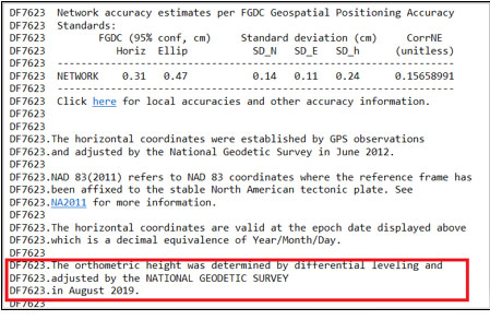
In August 2019, NGS performed a large leveling network adjustment in the Minnesota. The adjustment was performed after the Geoid18 database pull. The adjustment resulted in a 7- to 9-cm bias between the published height values and the superseded values. The August 2019 Minnesota leveling network adjustment heights were not used in the creation of Geoid18. The post-modeled differences presented in this column were generated using the published NAD 83 (2011) ellipsoid heights and current NAVD 88 orthometric heights from the NGSIDB. It was determined by NGS that the differences in the Fargo region were mostly due to crustal movement. Therefore, since the differences were due to movement, secondary adjustments will need to be performed to feather the 7- to 9-cm differences to maintain consistency between published NAVD 88 heights in the region. The secondary adjustments have not been completed as of the publication of this column so the residuals west of Fargo in North Dakota are small. These values will change after the secondary adjustment is completed and loaded into NGS’ database.
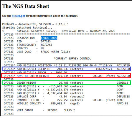
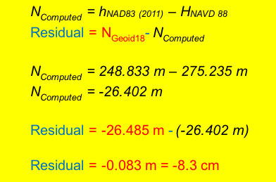
As an example, I’ve highlighted the station Fargo 0009 (PID DF7623) in the area of Fargo, North Dakota (see box titled “Differences on GPS on Bench Marks Near Fargo, ND”). The difference (-8.3 cm) is between the published Geoid18 value and the computed geoid value using the published ellipsoid height and orthometric height from the NGS’ datasheet. The box titled “Excerpt from Datasheet for Station Fargo 0009 (DF7623)” provides the information from NGS datasheet for station Fargo 0009; the information used in the computations are highlighted in the box. The box titled “Computation of the Difference between the Modeled Geoid Value (Geoid18) and the Computed Geoid Value for Fargo 0009” provides the process used to compute all differences for this column.
Differences on GPS on Bench Marks Near Fargo, North Dakota
Image: National Geodetic Survey
Excerpt from Datasheet for Station Fargo 0009 (DF7623)
Data: National Geodetic SurveyData: National Geodetic SurveyData: National Geodetic Survey
Computation of the Difference between the Modeled Geoid Value (Geoid18) and the Computed Geoid Value for Fargo 0009
(Information from NGS Published Datasheet)
Data: National Geodetic Survey
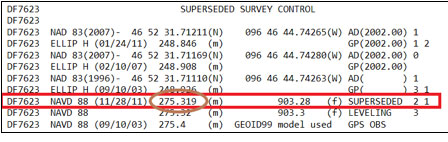
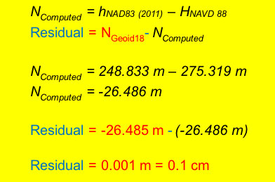
So, why is this difference so large in this region? A stated above, NGS performed a readjustment in this region and superseded the heights that were used in the creation of the Geoid18 hybrid model. The Geoid18 hybrid model used the previously published orthometric heights, now provided in the superseded section of the NGS datasheet, because that was the current published height at the time of the data pull for the Geoid18 process. Therefore, if we substitute the superseded height from the datasheet into the equation the difference is reduced to 0.1 cm (1 mm). [See the box titled “Computation of the Difference between the modeled geoid value (Geoid18) and the computed geoid value for Fargo 0009 Using the Superseded NAVD 88 Value.”]
Computation of the Difference between the modeled geoid value (Geoid18) and the computed geoid value for Fargo 0009 Using the Superseded NAVD 88 Value
(Information from NGS Published Datasheet)
Data: National Geodetic Survey
This means if someone uses NGS’ OPUS web tool to compute a GNSS-derived orthometric height, the NAVD 88 GNSS-derived orthometric height will be about 8 cm different than the published stations in this region. This should not be an issue if the users follow published NGS Guidelines to estimate the NAVD 88 GNSS-derived orthometric height, and/or uses NGS Beta OPUS-Projects and NGS procedures to estimate the NAVD 88 GNSS-derived orthometric height. These processes will ensure that the height will be consistent with the current published NAVD 88 orthometric heights in the NGS database.
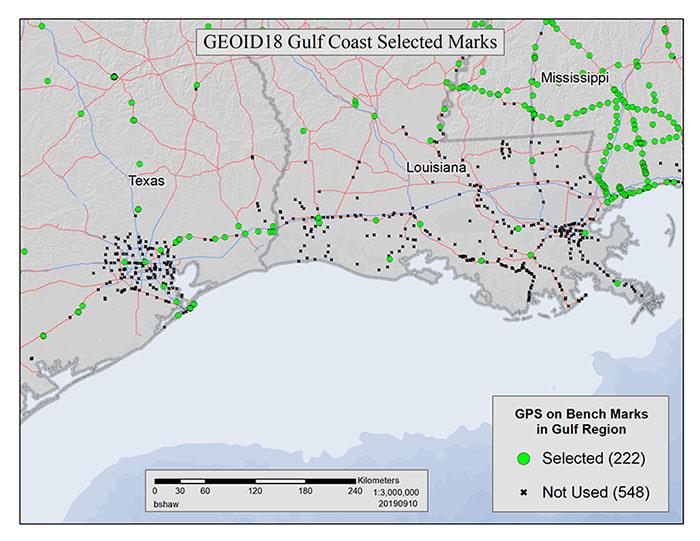
The technical report on Geoid18 provides a good explanation on the stations used in the United States Gulf Coast region. See box titled “GPS on Bench Marks for GEOID18 in the Gulf Coast Region.”
GPS on Bench Marks for GEOID18 in the Gulf Coast Region
There are areas of complex vertical crustal motion in the Texas/Louisiana Gulf Coast region of the United States which render many control station elevations in the region invalid. The selection of GPS on Bench Marks in this region was limited to the small number of marks where the leveling and GPS data agreed to minimize the influence of crustal motion in the hybrid geoid model. Figure 1 depicts the selection of stations used in the hybrid geoid model along the Texas/Louisiana Gulf Coast.
As indicated in the box titled “GPS on Bench Marks for GEOID18 in the Gulf Coast Region” very few stations in Southern Louisiana were used in the creation of the hybrid geoid model. The box titled “Differences on GPS on Bench Marks in the Gulf Coast Region” depict the differences between the published Geoid18 value and the computed geoid value using the latest NAD 83 (2011) ellipsoid and NAVD 88 orthometric height. The plot indicates that there are many large differences. This is to be expected because the orthometric heights used in the creation of the hybrid geoid model are all superseded heights. This is because the only published heights in Southern Louisiana are GNSS-derived orthometric heights and leveling-derived orthometric heights were used in the creation of GEOID18.
Differences on GPS on Bench Marks
in the Gulf Coast Region
Image: National Geodetic Survey
Saying that, NGS performed a large GNSS network project in Southern Louisiana in 2016. At the time of the writing of this column, the GNSS-derived orthometric height from the 2016 project were not yet finalized.
This column provided an analysis of the differences between the latest published hybrid Geoid18 values provided on NGS’ Datasheet and the computed geoid height value using the published NAD 83 (2011) ellipsoid height and NAVD 88 orthometric height. The column highlighted issues on differences due to published heights that have changed since the database pull for Geoid18. Future columns will address differences in other portions of CONUS.
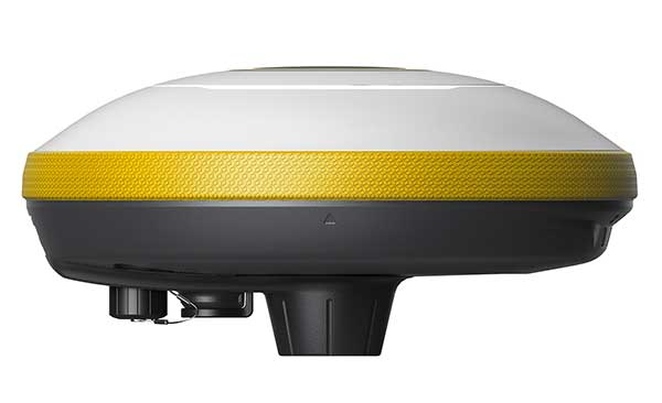
The interface adopts a concealed design for better protection, and USB type-C charging and transmitting is a two-in-one function.
The magnesium-alloy body is rugged and the battery level can be checked with a unique LED power indicator. The weight of the whole receiver is 940 grams.
The E300 Pro supports satellite station differential and satellite chain life, quick connection, intelligent voice, and tilt compensation. The E300 Pro tracks GNSS with 700 channels and fully supports BDS-3 signals. It supports 31 frequency points, using all GNSS satellite systems and frequency bands.
Inertial integration. The E300 Pro integrates multiple sensors including GNSS, an inertial measurement unit (IMU) , a magnetometer and a thermometer. With the help of a Kalman filter algorithm, the device can dynamically output position, speed and attitude information. It can measure and make real-time dynamic sampling without the need for leveling.
Combined GNSS Antenna. For better radio signal quality, the E300 Pro integrates GNSS, Bluetooth, Wi-Fi, 4G main and auxiliary antennas on the top of the receiver to ensure the best reception in all directions. An innovative RF connector greatly improves connection reliability, while reducing loss of gain.
Founded in 2005, e-Compass provides data acquisition and positioning equipment including high-precision GNSS receivers, GIS data collectors and combined inertial navigation products.The company is based in Shanghai, China, with offices in the United Kingdom and Hong Kong.
What are the key technical criteria in matching GNSS receivers and antennas from the same or different manufacturers? For what uses does it matter most?
John Fisher. (Photo: Orolia)
“For fixed-pattern antennas, it’s fairly simple: RF + DC to power the antenna. Most vendors are compatible. The challenge is more for controlled radiation pattern antennas (CRPA). Power requirements vary greatly, and performance can be improved with a two-way data exchange between the CRPA and receiver, but there is no industry standard yet for this interface. An example: tilt angles from the receiver’s IMU can greatly aid beam pointing.” John Fischer Orolia
Ellen Hall
“Antenna selection is exceptionally critical for our military and high-precision users. The platform and environment are the primary drivers of these antenna requirements. In general, SWaP (size, weight and power) is at the forefront of all criteria. As operational plans are developed, requirements for a single or multi-element array, element gain, and noise figure must be considered.” Ellen Hall Spirent Federal Systems
Members of the EAB
Tony Agresta Nearmap
Miguel Amor Hexagon Positioning Intelligence
Thibault Bonnevie SBG Systems
Alison Brown NAVSYS Corporation
Ismael Colomina GeoNumerics
Clem Driscoll C.J. Driscoll & Associates
John Fischer Orolia
Ellen Hall Spirent Federal Systems
Jules McNeff Overlook Systems Technologies, Inc.
Terry Moore University of Nottingham
Bradford W. Parkinson Stanford Center for Position, Navigation and Time
Top receiver manufacturers discuss what’s on the horizon for GNSS receivers. The companies reveal recent and upcoming innovations, how to combat spoofing and jamming, fusing GNSS with other sensors, and the impact of increasing accuracy both for professional surveyors and consumers.
With regard to jamming and spoofing, the preferred approach is a combination of monitoring, detection and filtering. However, shielding, the use of IMUs and other third-party sensors, and advances in processing algorithms also help mitigate interference. In a few years, hopefully, encrypted or “watermarked” signals will substantially reduce this problem.
IMUs and other sensors are now routinely integrated with GNSS receivers, with their outputs fused. This trend is largely propelled on the demand side by the needs of the emerging market for autonomous vehicles and on the supply side by smaller, cheaper and more accurate IMUs and lidar scanners. Meanwhile, developments in algorithms have improved the modeling of errors to correct for the inherent tendency of IMUs to drift. Additionally, digital cameras, lidar and other industry-specific sensors are increasingly common, especially for collision avoidance in human-machine interactions.
In surveying, the use of all constellations and frequencies, as they become available, is an industry trend. Costs will continue to drop as the growth in the adoption of GNSS solutions enables manufacturers to take greater advantage of economies of scale. Precise point positioning (PPP), which benefits greatly from the growth in GNSS constellations, is now giving real-time kinematic (RTK) positioning a run for its money. Available applications enable Android mobile devices to achieve centimeter accuracy, while innovations continue in core positioning algorithms.
In the world of mobile consumer devices, dual-frequency, multi-constellation GNSS chipsets are increasingly prevalent. As increased accuracy fuels expectations for even higher accuracy, precision positioning may become the norm in the consumer space, and new applications for these devices may emerge. Already, crowdsourcing the monitoring of both GNSS signals and interference helps improve accuracy for everyone, in a positive feedback loop.
Other notable trends include the introduction and expansion of 5G data networks, the increased use of satellite-based correction services, and continued efforts to develop precise positioning for indoor areas. (See part 2 of this feature here.)
Topcon
Jamming and Spoofing. “We continue to develop and deploy patented technology to detect spoofing,” said Alok Srivastava, director, product management. “We already have cutting edge GNSS antenna technology to provide stellar support for interference rejection and filtering.” All Topcon end products have this advanced antenna and filtering technology.
Sensor Fusion. “Topcon has been using inertial systems for decades for a variety of positioning applications — such as machine control, mobile mapping, and agriculture,” said Srivastava. “In recent years, advancements in IMU technology have progressed to where the size and cost of these sensors are at levels to be utilized at a larger scale. For example, the recently released Topcon HiPer VR takes advantage of inertial technology to improve productivity in real time with our Topcon Integrated Leveling Technology (TILT), which compensates for mis-leveled field measurements out of plumb by as much as 15 degrees.”
Surveying. Topcon continues to invest in its core positioning algorithms to innovate such features as quartz lock loop, advanced multi-engine platform, and VHD heading technology into its positioning engines, Srivastava said. “We also produce solutions such as our Millimeter GPS and Hybrid Positioning innovations, which are designed around improving accuracy, higher reliability, and greater flexibility by converging positioning technologies.”
Consumer Devices. “GNSS in consumer devices and other commercial systems is used to aid other positioning sensors,” Srivastava said. “So, it may not be in the best of interest to offer that level of accuracy from GNSS alone.”
Other Challenges. Precise indoor positioning is a requirement of the vertical construction industry. “Topcon’s combined optical instrument takes a unique approach to solve that problem by integrating a compact laser scanner with a fully featured robotic total station,” Srivastava said.
Photo: CHC Navigation
CHC Navigation
Jamming and Spoofing.CHCNav is currently taking a twofold approach to GNSS interference, said François Martin, vice general manager, International Division. “As a GNSS system integrator, we focus our design around strong electromagnetic shielding and sealed isolation chambers.” Additionally, he pointed out, the advanced filtering of GNSS signals and an antenna patch produce optimal interference mitigation.
Sensor Fusion. Integrating interference-free, high-dynamic IMUs instead of MEMS has brought the full benefits of tilt compensation to users, Martin said. The latest development in algorithms dramatically obviated the need for the annoying process of initializing GNSS IMU receivers and boosted the availability of GNSS RTK in demanding environments.
Surveying. The fast adoption of GNSS solutions by large user segments has reduced costs by enabling a sizable manufacturing economy of scale, Martin pointed out. “Tighter combination of embedded technologies such as GNSS and connectivity modules are sustaining that cost reduction process.”
Consumer Devices. “The emergence of dual frequency multi-constellation GNSS chipsets supports the development of untapped user segments, but the position accuracy repeatability remains an issue,” Martin said. “The integration of GNSS chipset and high-performance helical antennas, as precision add-on modules, onto rugged Android cell phone and tablets is creating a prosumer-grade centimeter to decimeter accuracy answering to a wide range of mobile workforce applications.”
Other Challenges. A growing number of positioning and navigation applications require the fusion of technologies to increase productivity, Martin said. “The integration of advanced tightly integrated positioning algorithms, scanners, IMUs, HDR cameras, IoT and cloud-based connected solutions are a clear trend.” However, their adoption by a large user base remains limited by their current price point.
Photo: Septentrio
Septentrio
Jamming and Spoofing. “Recent developments in receiver-antenna combinations maximize the benefits of anti-jamming techniques,” said Gustavo Lopez, market access manager. Third party sensors, such as IMUs, also help mitigate interference, he pointed out. “Septentrio’s advanced receiver technology such as AIM+, a standard feature on all the company’s products, bring not only real time monitoring but also jamming/spoofing mitigation. Galileo and GPS have clear roadmaps bringing signal authentication in order to avoid spoofing.”
Sensor Fusion. Smaller IMUs with higher grade performance now on the market are enabling new use cases in autonomous applications, said Lopez. Other important elements are a new generation of compact high-performance sensors and the growing importance of multi-sensor technology “to provide even higher levels of positioning integrity.” He cited Septentrio’s AsteRx-i family of products as an example of GNSS/INS integrated solutions.
Surveying. As an example of Septentrio’s survey-specific products, which “continuously benefit from advanced developments being rolled out in our platform,” Lopez cited the Altus NR3.
Consumer Devices. The increasing positioning accuracy of cell phones, Lopez pointed out, “has spurred innovations such as PPP and the use of mobile phone measurements,” as well as “other purposes, such as interference detection and crowdsourcing.”
Other Challenges. “Sensor fusion is a key element in positioning and orientation,” Lopez said. “Easy integration is a key element in this trend. Also, integrity in error reporting and positioning will be required as well as reliable raw measurements which can be integrated with other sensors. This drives the requirement for receivers capable of running customer proprietary software. Another important element will also be the possibility of running positioning algorithms on a third-party processor.”
Photo: Hemisphere GNSS
Hemisphere GNSS
Jamming and Spoofing. “Hemisphere’s new Lyra II ASIC platform used in our Phantom and Vega series positioning and heading boards,” said Miles Ware, director of marketing, “introduces new technology and filtering methods to identify and mitigate known and unknown interference sources that typically have an adverse effect on GNSS performance.”
Sensor Fusion. “Advancements in IMU integration and sensor fusion,” Ware said, “will continue to be a key focus for Hemisphere to support the growth and adoption of the expanding autonomous vehicle and application marketplace. The positioning and heading technology offered in our Vega 28 will be a core component for autonomous marine, machine control, and agriculture solutions for new and emerging markets.”
Surveying. “Access to modern and future signals like BeiDou Phase III, ALTBOC and BS-ACEBOC significantly enhance GNSS accuracy, especially in challenging environments where satellite visibility is compromised by the topography and or the structures present,” Ware pointed out. “Survey solutions that can not only track but also use all the available GNSS measurements in their RTK solution will have a substantial advantage in the market.”
Consumer Devices. “As mobile phones and consumer devices continue to adopt hardware designs that can access the latest GNSS signals,” Ware said, “the opportunities for solutions where high precision measurement engines can be hosted within mobile devices opens up a new realm of solutions that can leverage the high accuracy positioning performance found in Hemisphere technology and products. We see this as a very exciting and emerging area.”
Other Challenges. Ware pointed to “leveraging GNSS technology to further support environmentally friendly transportation solutions and sustainable agriculture,” for which GNSS continues to be an integral component.
Photo: Unicore
Unicore Communications
Sensor Fusion. “We are implementing GNSS with different level IMUs, including low-cost and high-end, targeting automotive, intelligent driving, and robot application scenarios,” said Gao Jingbo, marketing director. “The algorithm can also integrate with the already-existing sensors on the platform, such as IMUs, cameras and odometers. The solution can be done on the GNSS side, with high information synchronization accuracy, or processed on the platform.”
Surveying. Products with Unicore boards inside can provide centimeter- to millimeter-level positioning accuracy, said Jingbo. “Unicore’s high-precision boards and modules can track all frequencies of all satellite systems. The UGypsophila RTK technology can make the most of the observation data of all frequencies in all systems even without the observations of the base station in the RTK solution, thus greatly improving the usability, reliability and accuracy of RTK.” The company is now also working to reduce the dimensions and cost of its products, Jingbo pointed out. “With Unicore’s single GNSS SoC on board, the UB4B0M and UM4B0 modules are making affordable high-end high precision surveying possible.”
Consumer Devices. Algorithms and hardware are ready now to implement PPP+RTK in cell phones, Jingbo said, and this increase in positioning accuracy will enable many more applications. “We have rich experience in high precision GNSS, but the antenna might be a challenge. Our new generation 22 nm GNSS SoC features low power consumption and support of sensor fusion. Additionally, true point technology by Rx-Networks (also a BDStar company) can provide sub-meter data service, which also enables users to access centimeter-level accuracy location data through their mobile phones and wearable technologies, without increasing the demand for processing power.”
Photo: Trimble
Trimble
Jamming and Spoofing. “Trimble’s latest GNSS receivers leverage our seventh-generation Maxwell technology, which implements hardware- and software-based techniques to detect and mitigate spoofing,” said Stuart Riley, vice president, GNSS Technology. “In addition, Trimble continues to improve the robustness of our GNSS receivers with advances in processing algorithms and hardware enhancements such as the integration of inertial technology.”
Sensor Fusion. “For many years, IMUs have been widely used in Trimble agriculture and Applanix products,” Riley said. “Over the past few years, we’ve created a new line of lower-cost inertially integrated board-level GNSS receivers. We have also integrated inertial components into survey and construction products, including tilt compensation in the Trimble R10, R12 and SPS986 receivers. Trimble also combines its GNSS solutions with optical, laser, lidar and other sensors.”
Surveying. Trimble’s GNSS products, Riley pointed out, range from GIS handhelds to high-performance mobile mapping systems.
Consumer Devices. “The Trimble Catalyst system uses Android-based smartphones or tablets to run an application that includes a software-defined GNSS receiver,” Riley said. “The recently introduced SiteVision system builds on this ecosystem and integrates Google’s ARCore platform with precision GNSS to provide an augmented reality solution for a variety of professional applications.”
Other Challenges. To address signal masking and multipath, Trimble has “continued to improve performance in difficult environments with products such as the Trimble R12 receiver, which provides sophisticated multipath mitigation and an advanced precision processing engine.” Riley said, “Trimble’s RTX Correction Services, delivered via satellite, enable users to achieve RTK speed and accuracy nearly anywhere on the planet without the need for local reference stations.”
Photo: NovAtel
NovAtel
Jamming and Spoofing. “The RF environment is at best crowded and at worst hostile,” said Sandy Kennedy, vice president of innovation, Hexagon’s Positioning Intelligence division. “The NovAtel OEM7 generation of receivers was launched in 2016, with interference detection and mitigation as key features on every variant. Protecting authenticity, availability, and precision for multifrequency measurements is the challenge going forward — in all segments of the system: constellation management and SIS, antenna, receiver design and processing in FW/SW.”
Sensor Fusion. In the last three years, Kennedy pointed out, IMU manufacturers have made significant improvements in the performance offered in smaller, cheaper IMUs. “At the same time, new methods to improve error modelling (to control positioning errors) have been added to the NovAtel SPAN product line, especially in SPAN Land profile. Extended GNSS outages are easily handled now.”
Surveying. “PPP has become a strong competitor to RTK, as convergence times have decreased, and this will continue in service offerings like Terrastar-X from NovAtel,” Kennedy said.
Consumer Devices. The devices, Kennedy said, offer “the tantalizing promise of quality measurements from a common utility device with huge computing horsepower and data connectivity built in! It’s fun to watch, and we shall see if accuracy is truly addictive enough to fuel development for general use of precision positioning.”
Other Challenges. “In the past 20 years, users have moved from awe and wonder that centimeter-level positioning is possible — to utter contempt when it is not,” Kennedy said. “This will continue, with an added requirement of integrity and functional safety. Continuously available positioning within a usable protection level is a requirement for autonomous vehicles.”
Oceaneering C-Nav Positioning Solutions to provide C-Nav5000 GNSS receivers for select SEACOR marine vessels
The C-Nav5000 GNSS receiver. (Photo: Oceaneering)
Oceaneering C-Nav Positioning Solutions has been selected by SEACOR Marine to supply C-Nav5000 GNSS receivers for a select number of the company’s oil-and-gas support vessels worldwide.
The scope of work calls for C-Nav to provide two C-Nav5000 GNSS systems per vessel. SEACOR will license corrections signals from C-Nav while the equipment is onboard and the vessels are working. C-Nav expects to install the C-Nav5000 receiver on seven vessels by year’s end.
“We are delighted to have been selected by SEACOR to provide our precise point positioning receivers onboard their vessels,” said David Fitts, senior manager, C-Nav Positioning Solutions. “Our receivers will provide SEACOR vessels with the latest in GNSS hardware.”
The C-Nav5000 offers integrated GNSS capabilities that allow tracking of multiple systems. It features triple L-band channels for correction tracking and is software-configurable to user requirements.