What improvements will GPS III bring to high -precision surveying? When? Will these improvements require any changes in equipment and/or processes?
Tony Agresta, Nearmap
“The biggest impact of GPS III to high precision surveying will be a full constellation of L5 satellites. Triple frequency will bring faster convergence times and better accuracy in more difficult conditions. GPS III will better align with Galileo and BeiDou with L1C which means better availability in restricted sky conditions. Users will want to have equipment capable of supporting these new signals, in antenna and receiver HW as well as the signal processing done on board.” Tony Agresta
Nearmap
Jean-Marie Sleewaegen
“Of all the improvements brought by GPS III, the new L1C signal will probably have the biggest impact on high-precision surveying. Compared to L1 C/A, L1C brings better reception in difficult environments, improved availability thanks to the “pilot” component, enhanced resilience to jamming attacks, and better interoperability with Galileo, BeiDou and QZSS. Many receivers do support L1C already, but the benefits will become more tangible as the GPS III constellation grows.” Jean-Marie Sleewaegen
Septentrio
Members of the EAB
Tony Agresta Nearmap
Miguel Amor Hexagon Positioning Intelligence
Thibault Bonnevie SBG Systems
Alison Brown NAVSYS Corporation
Ismael Colomina GeoNumerics
Clem Driscoll C.J. Driscoll & Associates
John Fischer Orolia
Ellen Hall Spirent Federal Systems
Jules McNeff Overlook Systems Technologies, Inc.
Terry Moore University of Nottingham
Bradford W. Parkinson Stanford Center for Position, Navigation and Time
The HT1 is a slim, light, powerful “Android Enterprise Recommended” tablet
Photo: Janam
Janam Technologies, a provider of rugged mobile computers that capture data and communicate wirelessly, has introduced a powerful and advanced 8-inch rugged tablet. The HT1 is designed to improve line of business applications including put-away and replenishment, cross docking, shipping and receiving, inventory management, merchandising and clientele management.
Besides a stylish design paired with military-grade ruggedness, the HT1 offers dual-frequency GNSS using the u-blox M8 chip. It can provide accuracy within three feet in open skies and 15 feet in denser environments.
Janam introduced the tablet at the National Retail Federation Annual Conference and Expo (NRF 2020), taking place Jan. 11-14 in New York City.
As part of Google’s Android Enterprise Recommended (AER) program, Janam’s HT1 completed rigorous testing and is guaranteed to meet the most demanding enterprise-level requirements. AER certification also ensures a seamless deployment, familiar user experience and secure managed updates to deliver immediate improvements in productivity.
HT1 Facts
The HT1 rugged tablet provides latest-generation speed and performance and is purpose-built to thrive in any industry including retail, warehousing, manufacturing, field service, transportation, construction, law enforcement, hospitality and other tough work environments.
As a rugged tablet running Android 9 (with ability to be upgraded to future generations of Android) in Google’s AER program, the HT1 delivers a premium experience for mobile workers. Timely security updates extend the HT1’s product lifecycle while providing IT teams with more control to keep business-critical data safe and secure.
With LTE speeds up to three times faster than most 4G LTE devices, advanced Wi-Fi and Bluetooth technology, Janam’s HT1 provides robust connectivity and lightning-fast voice and data inside four walls and out on the road.
The versatile HT1 features a 14-pin pogo connector to easily attach accessories such as Janam’s optional 2D imager module to provide high-performance scanning of printed and mobile barcodes. High-resolution front and rear cameras provide HT1 users with additional data capture support for proof-of-delivery, proof-of-condition, proof-of-service and more.
Sealed to IP67 standards, the HT1 provides reliable operation in the rain, snow or dust. It is MIL-STD-810G certified to withstand tumbles, vibration, ballistic shocks and repeated drops to concrete across a wide temperature range.
Equipped with an 8200 mAh hot-swappable and rechargeable battery, as well as a low-power Qualcomm octa-core processor with efficiency-boosting features, the HT1 provides all-day battery life for uninterrupted usage and maximum productivity.
A standard two-year warranty provides customers with both peace of mind and the level of service they expect, at no additional cost, with optional comprehensive service plans available to those that want to further extend their mobile computing investment.
A roundup of recent products in the GNSS and inertial positioning industry from the January 2020 issue of GPS World magazine.
OEM
Heavy-duty antenna
For challenging environments
AT311 antenna. (Photo: CHC Navigation)
The heavy-duty CHCNAV AT311T is designed for demanding applications subject to shocks and vibrations. With advanced filtering and robust signal tracking, it provides survey-grade GNSS signals to enhance position reliability for marine applications, machine control, precision agriculture and industrial automation. Features include multi-constellation GNSS tracking using GPS, GLONASS, BeiDou, Galileo, QZSS, IRNSS and SBAS. Its IP68 water-resistant design makes it safe to use in extreme conditions with a wide temperature range (–40° C to +85° C). Its internal stacked structure enhances performance in high-interference environments, and the 40-dB signal gains, advanced signal filtering and multipath rejection design provide superior and robust GNSS signal tracking in challenging surroundings.
The UAS1 GNSS receiver module has been designed for UAV/UAS applications requiring centimeter accuracy in a small package.(Photo: Trimble)
The UAS1 compact, high-precision GNSS board was designed for unmanned aerial systems (UAS). It allows UAS system integrators to add upgradeable GNSS-based positioning using rugged connectors and Trimble’s software interface. Its 336-channel GNSS engine is capable of tracking L1/L2 frequencies from GPS, GLONASS, Galileo and BeiDou for centimeter-level, real-time kinematic (RTK) positioning. The compact board provides capabilities from high-accuracy GPS-only to full GNSS features. The receiver supports fault detection and exclusion (FDE) and receiver autonomous integrity monitoring (RAIM). System integrators also have the ability to detect interference with an RF spectrum monitoring and analysis tool embedded in the receiver.
The Onyx multi-frequency GNSS OEM board offers integrated StarFire/real-time kinematic (RTK) GNSS capabilities. It features 255-channel tracking, including multi-constellation support for GPS, GLONASS, BeiDou and Galileo. It provides high performance in GNSS receiver sensitivity and signal tracking as well as patented multipath mitigation, interference rejection and anti-jamming capabilities. Through software options, the Onyx ,allows upgrades from free differential GPS signal sources such as WAAS, to increased accuracy services such as StarFire and RTK Extend. The software-enabled features are sold in bundles, but can also be purchased individually to suit changing application needs.
The OSA 5401 and OSA 5405 now enable power utility and broadcast networks to achieve sub-microsecond synchronization. (Photo: Business Wire)
The OSA 5401 and OSA 5405 upgraded PTP grandmaster clocks deliver precise, robust timing in a compact form factor. Oscilloquartz PTP timing technology enables power utility and broadcast networks to achieve sub-microsecond synchronization. The pluggable OSA 5401 is a small PTP grandmaster clock, and the OSA 5405 is an integrated PTP grandmaster with dual GNSS antenna and receiver. With spoofing and jamming detection capabilities, they also provide high availability. The OSA 5401 and 5405 provide new levels of accuracy and resilience for infrastructure and support emerging bandwidth-intensive, latency-sensitive applications. With sub-microsecond synchronization, smart grids can perform flexible, real-time decision making, as well as monitoring and automated maintenance. The OSA 5401 and OSA 5405 comply with the latest PTP profiles for time, frequency and phase synchronization in both power utility and broadcast networks. These include the IEC/IEEE 61850-9-3 Power Utility Profile for precise time distribution and clock synchronization in electrical grids with an accuracy of 1μs, and SMPTE 2059 for synchronizing video and audio equipment over packet networks.
The SBAS-capable CMA-5024 GPS has received U.S. Federal Aviation Administration (FAA) approval for installation on Boeing 737 Next-Generation aircraft. It enables B737NGs to comply with worldwide ADS-B Out mandates as well as SBAS/GPS navigation, enabling the first localizer performance with vertical guidance (LPV) approaches for B737NGs. The CMA-5024 GPS is a cost-effective alternative to replace a multi-mode receiver (MMR). The approved DO-260B ADS-B Out positioning source can be paired with any DO-260B compliant transponder, allowing operators to meet FAA and EASA ADS-B Out requirements, the UAE’s ADS-B Out and RNP requirements mandated by GCAA as well as India’s GAGAN requirements.
The U.S. Federal Aviation Administration (FAA) has approved the VTU-20 automatic dependent surveillance – broadcast (ADS-B) transmitter for airport surface management. Adhering to the performance and design assurance specifications of FAA-E-3032, the externally mounted VTU-20 ensures integration and interoperability with Airport Surface Detection Equipment, Model X (ASDE-X), Airport Surface Surveillance Capability (ASSC) and ADS-B receiver surveillance solutions for airport. The VTU-20 can be permanently or magnetically mounted to all airside vehicles, including utility, emergency, snow-removal and maintenance equipment. Each vehicle is clearly and uniquely identified, providing an essential addition to any surface movement guidance and control system.
Skyward’s Advanced Airspace Intelligence drone airspace maps provide airspace data combined with essential ground intelligence including 3D views of key structures, transmission lines, and more than a million vertical obstacles. The platform also provides access to LAANC, the Low Altitude Authorization and Notification Capability program provided by the U.S. Federal Aviation Administration. Data available for situational awareness includes vertical structure obstacles, power lines, airports, runways, national parks, stadiums, hospitals and schools.
Hi-Target PPK GO precision add-on enables Phantom 4 RTK drones to achieve the accurate and reliable camera positioning data in any coordinate system without measure targets or ground control points. With 2-centimeter accuracies on XYZ, the output text file with position information or geotagged images can be used directly in major photogrammetric mapping or 3D survey software. The add-on allows selection of GPS/GLONASS/Beidou/ Galileo L1+L2+L5 and further parameter adjustments for position calculation in the PPK process to ensure the most reliable and accurate camera positioning even in poor single satellite system signals.
The R620 GNSS receiver is a complete refresh of Hemisphere’s previous version, the R330. (Photo: Allison Barwacz)
The next-generation R620 receiver is designed for land and marine applications requiring high-precision positioning. It is a complete refresh of the previous version (R330) and has a new low-profile ruggedized enclosure. Customers can start with sub-meter positioning accuracy and upgrade the receiver through activations and subscriptions to add functionality and improve performance capability to centimeter-level accuracy. Powered by the Vega series, the R620 GNSS receiver processes and supports more than 1,100 channels. It simultaneously tracks GPS, GLONASS, BeiDou (including Phase 3), Galileo, QZSS, IRNSS, SBAS and Atlas L-band corrections. It has status LEDs , a powerful WebUI, UHF (400-MHz and 900-MHz) radio, cellular modem, Bluetooth, Wi-Fi, Ethernet (including power over Ethernet), CAN, serial and USB.
For land surveying and geospatial information systems (GIS)
Photo: Geneq
The rugged SXPad 1500 data collector features an alphanumeric keypad and long-range Bluetooth, and was designed to meet the rigorous IP67 standard for challenging field conditions. It has a 5-inch sunlight-readable touchscreen. The SXPad 1500 can be connected to any GNSS receiver or compatible robotic total station. Driven by a 1-GHz processor and the Windows Mobile 6.5 operating system, providing the power to work with maps and large data sets in the field. Its integrated cellular modem and Wi-Fi provides wireless connectivity for internet access and GIS data transfer — helpful for configuring a real-time kinematic (RTK)-compatible GNSS receiver. Equipped with an internal memory of 1 GB (memory can be expanded to 16 GB with an SD card), the SXPad 1500 provides enough storage space for data recording. Its high-performance lithium battery allows uninterrupted field operation for up to eight hours.
The LT700H RTK Android tablet is designed to increase efficiency and productivity of the mobile field workforce in applications requiring centimeter-to-decimeter positioning accuracy. Portable, rugged and versatile, the LT700H enables precision GIS data collection, forensic mapping, construction site layout, environmental surveys, landscaping and earthmoving jobs. Powered by 184-channel high-performance GPS, GLONASS, Galileo and BeiDou module and a superior tracking GNSS helical antenna, the LT700H provides position availability in demanding environments. Its integrated 4G modem ensures seamless communication from field-to-office and robust connectivity to RTK correction networks.
The Trimble Alloy GNSS reference receiver now supports BeiDou Generation III (BDS-3) signals. This will enable operators to meet the ongoing demand from surveyors, mapping professionals and precision farmers for accurate, reliable corrections derived from real-time networks. Released in 2018, the Alloy has the processing power needed for high-quality data from multiple constellations. Alloy version 5.42 firmware tracks all available and planned GPS Block IIIA L1C and BDS-3 signals.
Hexagon showcased the Leica DSX utility detection solution at Intergeo 2019. (Photo: Allison Barwacz)
The Leica DSX utility detection solution can be used together with Leica GPS/GNSS systems to generate highly accurate, georeferenced maps. The DSX uncovers utilities for repair and maintenance, civil engineering and surveying projects. The ground-penetrating radar system includes portable hardware and software that automates data analysis and creates a 3D utility map.
J-Shield is a robust filter on Javad GNSS antennas that blocks out-of-band interference (Figure 1). In particular, J-Shield blocks signals that are near the GNSS bands, including the proposed Ligado Networks (formerly LightSquared) broadband signals, explained Javad Ashjaee, founder and CEO of Javad GNSS.
FIGURE 1. Protection characteristics: The J-Shield filters have a sharp 10-dB/KHz skirt, which provides up to 100-dB of protection. (Image: JAVAD GNSS)
The anti-jam digital filters protect against in-band interference such as the harmonics of nearby TV and radio stations, or against illegitimate in-band transmissions. The anti-jam filters can be combined in pairs for complex signal processing and can simultaneously suppress several interference signals.
“The filters make the near band spectrums available for other uses,” Ashjaee said. “They protect GNSS bands now and in the future.”
In-Band Noise Measurement. The receiver measures the level of interference as a percentage of noise above the normal condition. Figure 2 shows the condition in a clean environment, where eight GPS satellites were visible, according to the almanac. In all, eight C/A, six P1, six P2, six L2C and two L5 GPS signals were tracked. The noise level was 2% on C/A and L5 and 0% on P1, P2, and L2C.
FIGURE 2. Clean environment. (Image: JAVAD GNSS)
Figure 3 shows 290% noise in the GPS C/A signal and 121% noise in Galileo E1. Only one of the eight GPS C/A code and none of five Galileo E1 signals could be tracked because of the high level of interference.
FIGURE 3. High interference levels. (Image: JAVAD GNSS)
Spectrum Analyzer
Filters in the GNSS antenna provide one way to protect GNSS signals from interference. Another is the receiver chip itself. For instance, the Javad GNSS Triumph chip includes an integrated spectrum analyzer — a more efficient solution than using a commercial spectrum analyzer to continuously monitor and evaluate the environment, Ashjaee explained.
The spectrum analyzer monitors the spectrum inside the chip. It has an effective bandwidth of 1 KHz, and can be programmed to automatically record the spectrum (and other information) periodically or according to pre-set conditions. Each spectrum shows the power and shape of any interfering signals and jammers.
Figure 4 shows the shape of the GPS L1 band spectrum when the band is jammed, as indicated by the huge peak in the center where the C/A code is. The number on the bottom left is the height of the peak. The height of the spectrum is 21.1 dB; compared to a calm spectrum of 11.2 dB, this spectrum indicates a jamming impact of about 10 dB.
FIGURE 4. The L1 band is jammed, as shown by the peak. (Image: JAVAD GNSS)
Automatic Gain Control. In addition to monitoring the spectrum, the Triumph chip also keeps a record of automatic gain control (AGC) — another indicator of unwanted external signals. The AGC monitors the environment and adjusts the gain to keep the voltage at a certain level. The change in AGC is an indicator of interference.
Spoofers
“Spoofers are quite different from jammers,” Ashjaee said. “They don’t disturb the environment and the spectrum shape. They broadcast a GNSS-like signal to fool the GNSS receivers to calculate wrong positions. We detect spoofers by digital signal processing.”
With 864 channels and about 130,000 fast-acquisition channels in the Triumph 2 chip, it has the resources to assign more than one channel to each satellite to find all of the signals transmitted with the same GNSS PRN code — including spoofed signals.
“If we detect more than one reasonable and consistent correlation peak for any PRN code, we know that we are being spoofed and can identify the spoofer signals,” Ashjaee said. The chip isolates and ignores the wrong peak.
“Usually more than 100 signals are available at any given time. We need only four good signals to compute position,” Ashjaee said. “We reject infected signals, and then among all the available GPS, GLONASS, Galileo, BeiDou, IRNSS and QZSS signals, we use the healthy ones. It is extremely unlikely that we can be spoofed without our knowledge. We can immediately recognize spoofing and take corrective actions. In the rare case that all signals are affected, we inform the user and guide them to use a compass and altimeter to get out of the jammed area.”
Figure 5 is a screenshot from the company’s Triumph-LS survey receiver, showing the details of each signal tracked. The first six lines in this screenshot show the spoofed signals that were detected as soon as they appeared (number “1” in the C1 column). Percentages show the amount of interference above the normal level.
In the last column, T indicates the signal was tracked by the main channels, Q by the fast-acquisition channels, and U indicates the signal was used in position calculations.
Figure 5. Signal Details: The Triumph-LS receiver provides users with a wealth of information on each signal received, including spoofed signals.
Indicators for Healthy Signals
In addition to the spectrum shape and AGC, these other indicators show the health of GNSS signals:
Number of signals tracked.
Divergence of SNR from its expected value.
Level of additional power and its RMS.
Divergence of AGC from its normal value and its RMS.
Extra noise.
Number of signals spoofed.
As an aid to users, the company’s Triumph-LS receiver can display the status of all GNSS signals received. Figure 6 shows this compact view, with normalized values of the above indicators (0 means good and 9 means poor).
Figure 6. Signal Status. Information on all GNSS signals received as shown by the Triumph-LS. (Image: JAVAD GNSS)
Users of the Triumph-LS can click on any of the signal buttons to see the actual and normalized values of the indicators for that signal. Action buttons provide quick access to View Satellites, View Spoofing, View Spectrum and Take Spectrum. Jamming and spoofing protection is an option on all Javad GNSS products and OEM boards.
The National Geodetic Survey (NGS) has published a technical report that describes options for how NGS can implement a time-dependent geopotential datum and thus a time-dependent geoid model. My last column described the latest version of NGS’ VERTCON model. As mentioned in the column, NGS is developing these models and tools to support the implementation of the North American-Pacific Geopotential Datum of 2022 (NAPGD2022).
NAPGD2022 is going to be a time-dependent geopotential datum. In other words, the reference geopotential will change over time and therefore the geoid height value will change over time. NAPGD2022 was described in detail in NGS’ publication “Blueprint for 2022, Part 2: Geopotential Coordinates,” and my December 2017 column. Blueprint for 2022, Part 2 states that a gridded geoid model GEOID2022 will be created and it will contain two components:
The first component will be time independent, denoted as the Static Geoid model of 2022 (SGEOID2022).
The second component will be a time-dependent geoid undulation model, encompassing permanent geoid changes greater than or equal to 1 millimeter per year, denoted as Dynamic Geoid model of 2022 (DGEOID2022).
NGS will publish a GEOID2022 value that will be based on both SGEOID2022 and DGEOID2022. As stated in the document, GEOID2022 will be the official zero-height surface for orthometric heights within NAPGD2022, and thus within the NSRS. The box titled “Excerpt from Blueprint for 2022, Part 2, Figure 10-2” is a diagram that describes the process of creating the regional high resolution gridded GEOID2022 model. I have highlighted the GEOID2022 model and its two components, SGEOID2022 and DGEOID2022.
Excerpt from Blueprint for 2022, Part 2, Figure 10-2
Image: National Geodetic Survey
First, it’s important to note the role of the geoid in estimating GNSS-derived orthometric heights. As described in a previous column, GNSS-derived Orthometric Heights are computed using the following formula: orthometric height (H) = ellipsoid height (h) minus geoid height (N). See the box titled “NAPGD2022 GNSS-Derived Orthometric Height.”
NAPGD2022 GNSS-Derived Orthometric Height
Source: Slide 9 from Gillins and Fancher presentation titled “Leveling after 2022” presented at the 2017 Geospatial Summit
So, what does it take to compute a time-dependent geoid model and what is NGS’ plan to accomplish this project The technical report titled “ A Preliminary Investigation of the NGS’s Geoid Monitoring Service (GeMS)” describes options for how NGS can implement a time-dependent geopotential datum and thus a time-dependent geoid model (See box titled “NGS Publishes Report on GeMS”). The report contains too much information for a single column. This column will highlight some of the sections of the report. The document does contain a lot of technical information and I would encourage everyone to download the document.
The technical report describes the current state of knowledge and outlines next steps required to define a time-dependent geopotential datum for the Nation. NGS created a project called “The Geoid Monitoring Service,” or simply GeMS, to accomplish their long-term goal of establishing a time-dependent geopotential model.
The report addressed the following five topics:
A foundational introduction to the various types of geophysical phenomena that are causing both size and shape change to the geoid,
Geodetic observing techniques that are presently available to monitor geoid change,
An objective evaluation of NGS’s current ability to incorporate these techniques into a long-term monitoring service like GeMS,
Known barriers to accomplishing such a project, and
Potential observing techniques that might become available in the next 10-20 years, but are not currently mature enough for operational use.
The document presents a roadmap of options for how NGS could realize a time-dependent geopotential datum, and how NGS can support the dynamic datum into the future with independent validation surveys and datasets.
The report discusses the available geoid monitoring techniques that NGS has to support modeling the changes in the geoid. There are three existing NGS program areas and associated technical expertise that could be utilized in an operational GeMS:
NGS’s Gravity Program,
the NOAA CORS Network, and
GPS/geodetic leveling campaigns.
It is noted that individuals these techniques cannot provide 100% of what GeMS requires but combining various programs would be sufficient. The report does a great job of describing these three program areas. The box titled “Summary of Geoid Monitoring Techniques within NGS’ Current Expertise” is Table 3 from the Technical Report. The table list the affordability and accuracy attributes for each of the program areas. NGS’ Gravity Program provides high quality gravity data to internal and external stakeholders. The program provides gravity data required for NGS’s geoid modeling.
Summary of Geoid Monitoring Techniques within NGS’ Current Expertise
Source: National Geodetic Survey
The report provides a good overview of the expertise and instrumentation of NGS’ Gravity Program. The table titled “Summary of NGS’ Terrestrial Gravity Instruments” is a compilation of information on historical methods and instrumentation from the technical report.
Summary of NGS’ Terrestrial Gravity Instruments
FG5 Absolute Gravimeter. The FG5(X) absolute gravimeter is manufactured by Micro-g LaCoste Inc. in Lafayette, Colorado. It is currently the highest-accuracy, commercially-available absolute gravity meter, with an accuracy of about ±2 μGals. NGS owns and operates instrument number FG5X-102. (Source: National Geodetic Survey)
A10 Absolute Gravimeter. A field deployable version of the laboratory FG5 absolute gravimeter, was developed by Micro-g LaCoste in the early 2000’s. This instrument, now known as the A10, operates on principals nearly identical to the FG5 free fall gravimeter. However, the laser used in the A10 system is not a primary standard due to the low power and fragile nature of the Iodine based laser, and does need to be calibrated routinely. (Source: National Geodetic Survey)
Scintrex CG-6 Relative Gravimeter. The Scintrex CG-6 relative gravimeter is the newest generation of the CG line of quartz sensor relative gravity meters. The CG-6 (like its predecessors the CG-3 and CG-5) operates on the same fundamental theory as the LaCoste and Romberg G and D relative gravimeters, but uses a quartz sensor spring instead of a metal sensor. The primary advantage of a quartz sensor is its insensitivity to instrument shock or vibration that can cause offsets in the gravity measurements. (Source: National Geodetic Survey)
LaCoste and Romberg Relative Gravimeter. LaCoste and Romberg (L&R) relative land, air/sea, borehole, and tidal gravimeters have been manufactured by LaCoste and Romberg Gravity Meters, Inc. since 1959. The company later merged into Micro-g LaCoste, Inc., and the LaCoste land gravimeters were discontinued. Unlike the Scintrex gravimeters, these rely on metal zero-length-springs. (Source: National Geodetic Survey)
Superconducting Cryogenic Gravimeter. A superconducting cryogenic gravimeter is designed to be continuously monitor relative changes in the local gravity over time. It main applications include precise tidal analysis, ground water monitoring, and geodynamics. The precision of an SG is still unmatched by any other instrument at better than 0.1 μGals at short time scales. (Source: National Geodetic Survey)
gPhoneX Gravity Meter. The gPhoneX, manufactured by Micro-g LaCoste, is a low (linear) drift, metal spring-based gravimeter. Like the SG, it is designed to measure relative changes in gravity over time, at a fixed location. While not as precise as the SG at short time scales; at periods of longer than a few hours, the noise characteristics of the two instruments are quite similar. The advantages of a gPhoneX compared to a SG for long term monitoring include lower cost, lower power consumption, increased portability, and lack of a requirement for maintaining superconducting temperatures. (Source: National Geodetic Survey)
JILAg Absolute Gravimeter. The AFGL, JILA/IGPP and JILAg series of absolute gravimeters are the out-of-production predecessors to the FG5 gravity meter. These instruments were developed by James Faller and colleagues beginning in the mid-1970s, and were crucial for defining and providing the basis for the IGSN71, NGSGN, and other scientific projects. Agency (now NGA), the University of California at San Diego (IGPP), and NGS. (Source: National Geodetic Survey)
The document highlights something about the United States gravity data that most users don’t think about. That is, gravity values are referenced to a gravity network just like NGS’ published orthometric heights are referenced to the NAVD 88. In the mid-1950s, a coordinated effort was initiated by the International Association of Geodesy (IAG) to make gravimeter ties throughout collaborating parts of the world to support establishment of an International gravity datum.
It incorporated intercontinental, north-south, calibration lines and long-distance ties established by airplane. The majority of USA relative gravimeter work was done from 1965 – 1967, resulting in the network shown in the box titled “International Gravity Station Net of 1971 (IGSN71) in CONUS.” The report states that the calculations were completed by Urho A. Uotila of The Ohio State University around 1970.
The gravity network was constrained by a network of ballistic absolute gravimeters. Five of the eight absolute gravimeter sites were in CONUS. It was a world-wide, simultaneous adjustment and published as The International Gravity Standardization Net 1971 (I.G.S.N. 71). A
s of December 2019, the IGSN71 remains the official international gravity datum. Many of these stations have been destroyed over the decades, in particular those at passenger airport terminals.
International Gravity Station Net of 1971 (IGSN71) in CONUS
Figure 14: IGSN71 Gravity Stations. (Source: National Geodetic Survey)
In the mid-1970s, NGS was involved in two major readjustment projects, replacement of NAD27 with NAD 83 and the replacement of NGVD 29 with NAVD 88. At the same time, the NGS gravity group were evaluating the gravity data in NGS database and the gravity stations involved in the IGSN71. During the period 1975 and 1979, NGS and NGA (formally DMA) performed relative gravity surveys around CONUS to evaluate the stations.
A report by Robert Moose titled “The National Geodetic Survey Gravity Network” published by NGS in 1986 documents the results of the surveys. This network is denoted as the National Geodetic Survey Gravity Network (NGSGN) and depicted in the box titled “National Geodetic Survey Gravity Network (NGSGN) in CONUS.” The NGSGN was constrained by 8 absolute gravimeter stations and consisted of 232 stations. Differences between NGSGN values and IGSN71 values were computed to evaluate or detect change in gravity values.
The box titled “Gravity Differences between NGSGN and IGSN71 Common Stations” depict these differences. The report states “In summary, the gravity differences between NGSGN and IGSN are generally small and many of the larger differences may be due to vertical motion.
National Geodetic Survey Gravity Network (NGSGN) in CONUS
Figure 16: Difference between NGSGN and IGSN71 AG values [mgal] (Source: National Geodetic Survey)The basic rule of thumb for estimating land movement using gravity changes is: 1 meter of change equals 0.3086 mgals (1 cm of change equals 0.003086 mgals). It should be noted that a positive difference in gravity in the figure indicated apparent subsidence. As stated by the 1986 report by Moose, the large difference in Houston-Galveston region is most likely due to subsidence.
A report documenting the apparent movement in the Houston-Galveston region was published by NGS in 1980. The boxes titled “ Estimate of Subsidence in Houston-Galveston Area During 1963-78 Epoch” and “Estimate of Subsidence in Houston-Galveston Area During 1973-78 Epoch” provide estimates of the movement in the region that include the same epoch of the two gravity networks. These two plots agree with the summary statement in the 1986 report.
Estimate of Subsidence in Houston-Galveston Area During 1963-78 Epoch
NOTE: 30 cm approximately equals to 1 foot (Source: National Geodetic Survey)
What does all this mean to the geoid? Accurate and current gravity data are critical to the development of an accurate geoid model that includes estimating changes in the geoid model over time.
The technical report on NGS’ Geoid Monitoring Service (GeMS) describes geodetic and geophysical techniques that are currently known to NGS and show promise for GeMS (see the box titled “Summary of Known Geoid Monitoring Techniques that are currently outside of NGS’s Expertise). It should be noted that all of these techniques rely on a non-NGS entity to create a product (such as a model or dataset) that NGS can utilize in their products and services. This is nothing new; NGS leverages partnerships for other products such as the GOCO05S satellite gravity model produced by an ESA consortium led by the Technical University of Munich. This model is used by the NGS geoid team in static geoid modeling.
Summary of Known Geoid Monitoring Techniques that are currently outside of NGS’s Expertise
(Source: Table 7 from Technical Report NOS NGS 69)
Continuation of Summary of Known Geoid Monitoring Techniques that are currently outside of NGS’s Expertise
(Source: Table 7 from Technical Report NOS NGS 69)
As apparent by all of the types of data required to monitor the geoid, NGS has a challenging task to establish a Geoid Monitoring Service. Why is it important to invest resources to monitor the geoid? Analyzes of temporal satellite gravity missions provide changes in gravity values that can be use to create changes in the geoid. The GRACE (Gravity and Climate Experiment) satellite mission was designed to provide the temporal gravity field variations throughout its mission (duration 2002 – 2017). There are analysis centers that produce models using the GRACE data – University of Texas at Austin Center for Space Research (UTCSR), NASA Jet Propulsion Laboratory (JPLEM), and GFZ German Research Center for Geosciences (GFZOP). Release 6 denoted as RL06 is the most current GRACE data from these groups.
The data can be used to illustrate the magnitudes and resolutions that GRACE models provide to the seculargeoid rates for CONUS and Alaska. The boxes titled “GRACE Trend over CONUS from UTCSR RL06” and “GRACE Trend over Alaska from UTCSR RL06” are plots from Technical Report NOS NGS 69 that show these secular geoid trends from UTCSR-RL06. The plots indicate very small changes in the geoid but they are significant if the goal is to monitor the geoid model to the mm/year level.
GRACE Trend over CONUS from UTCSR RL06
Figure 27: GRACE Trend over CONUS from UTCSR RL06 Model [mm/yr] (Source: Figure 27 from Technical Report NOS NGS 69)
GRACE Trend over Alaska from UTCSR RL06
Figure 28: GRACE Trend over Alaska from UTCSR RL06 GRACE Model [mm/yr] (Source: Figure 28 from Technical Report NOS NGS 69)Another product available from various processing centers are surface mass concentrations (mascons) as observed by the GRACE satellites. Once again, these mascons can be used to generate a secular geoid rate. The boxes titled “Geoid rate over CONUS based on the GSFC mascon model” and “Geoid rate over Alaska from GSFC mascon model” are plots from Technical Report NOS NGS 69 that provide the secular geoid rate based on the NASA GSFC mascon model. Once again, the plots indicate very small changes in the geoid but there is a systematic change to the geoid based on the analysis of the data from the GRACE mission.
Geoid rate over CONUS based on the GSFC mascon model
Figure 32 From Technical Report NOS NGS 69: Geoid rate over CONUS based on the GSFC mascon model [mm/yr] (Source: Figure 32 From Technical Report NOS NGS 69)
Geoid rate over Alaska from GSFC mascon model
Figure 33 From Technical Report NOS NGS 69: Geoid rate over Alaska from GSFC mascon model [mm/yr] (Source: Figure 33 From Technical Report NOS NGS 69)The report stated that when considering monitoring the geoid, the greatest change to the geoid from glacial isostatic adjustment (GIA) processes is centered in northern Canada, but there is “still a significant geoid height trend in the Northern Plains, Great Lakes, and Northeast regions of CONUS.”
It was noted that if GIA processes are not considered, a 1 cm error in the geoid undulation would occur within 18 years. NADGPD2022 orthometric heights are going to be established using a NATRF2022 ellipsoid height and a GEOID2022 geoid height. This is why the geoid needs a time-dependent component.
This column highlighted NGS new Geoid Monitoring Service (GeMS); and, that NGS’ will be publishing a gridded geoid model GEOID2022 that will contain two components:
The first component will be time independent, denoted as the Static Geoid model of 2022 (SGEOID2022) and
The second component will be a time-dependent geoid undulation model, denoted as Dynamic Geoid model of 2022 (DGEOID2022).
NGS will publish a GEOID2022 value that will be based on both SGEOID2022 and DGEOID2022. The column provided examples of how GRACE data can be used to illustrate the magnitudes of secular geoid rates for CONUS and Alaska.
Trimble has acquired Cansel Survey Equipment’s Can-Net and AllTerra New Zealand’s iBase networks. The acquisitions significantly increase the global footprint of Trimble-owned Virtual Reference Station (VRS) networks by adding key geographies in North America and New Zealand.
Subscription-based VRS correction services are now accessible to more customers around the world who rely on high-accuracy corrections to increase productivity and reduce operational costs. The correction services are designed for professionals in agriculture, geospatial and construction as well as emerging high-accuracy applications, such as on-road positioning for passenger vehicles. Financial terms were not disclosed.
The Can-Net and iBase acquisitions add over 1.1 million square kilometers (over 425,000 square miles) to Trimble’s correction services coverage that has grown robustly over the past eight years, contributing to Trimble’s shift toward software, services and subscription business emphasis.
Can-Net Network. The Can-Net network comprises multiple VRS networks and single-base solutions offering GNSS corrections across Canada. The acquisition provides Trimble with the largest VRS footprint in Canada, covering more than one million square kilometers (386,000 square miles).
Subscribers primarily work in the agriculture, survey and construction industries. In addition, the Can-Net network enables Trimble corrections technology to be used by automotive stakeholders deploying ADAS systems along the Trans-Canadian Highway.
iBase Network. The iBase network expands Trimble’s VRS footprint across both the north and south islands of New Zealand, totaling more than 100,000 square kilometers (39,000 square miles).
“The high-accuracy precision provided by VRS technology is a powerful tool in driving operational and financial efficiency for industries that require easy access to positioning services,” said Patricia Boothe, vice president of Trimble’s Advanced Positioning Division. “We are aggressively expanding the accessibility of VRS corrections around the globe. Our vision is to make high-accuracy positioning available to the broadest base of commercial users worldwide for applications in agriculture, construction, automotive, autonomy and others where precise positioning is a critical part of the solution. Trimble will continue to invest in technology and infrastructure to push the boundaries of performance and accessibility for our portfolio of services.”
Trimble networks are supported by a global network operations team made up of GNSS system engineers, geodesy experts and IT professionals. The team monitors the networks 24/7 from operation centers located on three continents, ensuring consistent and reliable service uptime and performance integrity.
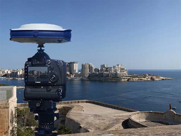
Verified photomontages for UNESCO World Heritage sites achieves accuracy with Spectra Geospatial SP80
Verified photomontage is an important planning tool to envision how proposed surrounding development plans would affect UNESCO World Heritage sites. Verified photomontage demands the best accuracy for the best visualization to determine what a development may look like to a person standing at the photographic viewpoint.
For MS Environmental (MSE), selected to provide verified photomontage for multiple UNESCO World Heritage sites, including in the UK Royal Botanical Gardens at Kew and the City of Bath, the Spectra Geospatial SP80 GNSS receiver enabled the highest quality visualization.
“The one-centimeter accuracy delivered by the SP80 is essential,” said Mike Spence, a verified photomontage specialist and founder of MSE. “The highest level of accuracy in the relationship between the actual camera location and the 3D model camera gives confidence in the visualization. In addition, The SP80 offers both simplicity and a robust design though it’s taken a few knocks over the years, it gives us the confidence we can use the equipment anywhere in the world and get the best results.”
At Kew Gardens, MSE was commissioned to produce accurate visualizations of views from within the UNESCO World Heritage Site. There was concern about development proposals for tall tower blocks in west London and how these might affect historic views from Kew Gardens.
The work culminated in a public inquiry, where evidence was presented that showed how views would change as a result of the proposed development. “Without the level of accuracy provided by the SP80 together with a transparent technical methodology it would have been unclear precisely how these historic views would change,” Mike Spence said.
At the UNESCO World Heritage City of Bath, the Bath and North East Somerset Council commissioned MSE to produce technical photography from strategic views around the World Heritage City to show how development proposals would affect strategic views across the city.
Trimble, Hilti and Boston Dynamics are collaborating to explore the integration of Trimble’s and Hilti’s construction-management software solutions, GNSS technology and reality-capture devices with Boston Dynamics’ Spot Robot platform.
Autonomous robots can play a significant role in construction, specifically in production and quality control workflows by enabling automation of routine and tedious tasks, reducing workload and improving safety. The companies will collaborate to develop a “proof-of-concept” solution.
Equipped with Trimble’s and Hilti’s reality capture devices as its payload and directly communicating with a cloud-based construction management application, the Boston Dynamics Spot Robot will be able to provide consistent output, deliver improved efficiency on repeatable tasks and enable up-to-date as-built data analysis.
The autonomous, terrain-agnostic capabilities support the dynamic nature of the construction environment, enabling the robot to bypass obstacles and maintain its defined path to support routine tasks such as daily site scans, progress monitoring, asset management and remote support.
Multi-directional communication between the robot, Trimble’s and Hilti’s payloads and the cloud application support a continuous flow of information and closes the loop for the construction environment.
“Utilizing robots for routine tasks in hazardous environments to improve safety, efficiency, and data capture consistency is part of our digital transformation vision” said Aviad Almagor, senior director for Mixed Reality and Brain-Computer Interface (BCI) at Trimble. “We are excited for this latest collaboration and looking forward to the potential integration of our hardware and software solutions with the Boston Dynamics’ Spot Robot to enhance field-oriented workflows, reduce amount of rework and facilitate on-site tasks.”
“Trimble’s and Hilti’s domain knowledge, market leadership and technologies are a great fit for our robotic platform,” said Michael Perry, vice president of Business Development at Boston Dynamics. “Deploying an integrated solution in the real-world environment doing dirty and dangerous work, before, during and after the construction stage is a common vision for the three companies, which can help drive the transformation of the construction industry.”
Septentrio’s post-processing kinematic (PPK) software has been upgraded with multi-GNSS and BaseFinder functionality. BaseFinder improves project efficiency by automatically finding the most suitable reference station data needed for centimeter-level accuracy.
Both GeoTagZ and PP-SDK now feature BaseFinder, which speeds up survey workflow by automatically finding reference data needed for augmenting GNSS logs with sub-centimeter accuracy. BaseFinder accesses an online database of reference networks and extracts the most suitable corrections available. BaseFinder is available via an app or via an API and can be incorporated into any existing software.
PPK is often used for ground surveys with aerial drones, allowing high precision georeferencing without the need for a real-time base station link or ground control points (GCPs).
“Surveying without a base station will allow users to reduce costs and set-up time. With this PPK upgrade we are improving the end-user experience as well as developer experience,” said Danilo Sabbatini, product manager at Septentrio.
The new release of this GNSS post-processing software also includes two additional GNSS constellations: European Galileo and Chinese BeiDou. Having access to all the signals from all GNSS constellations improves reference network compatibility. It also improves positioning availability in difficult environments. This is particularly important when working in areas of low satellite visibility such as near tall structures or under foliage.
When doing photogrammetry with a drone, GNSS data is often recorded and then post-processed together with base station data to achieve sub-centimeter positioning accuracy. This base station data can be obtained either with proprietary base stations or by using base station data from a public reference network (see diagram below). Septentrio receivers are designed to bring accurate and reliable positioning to photogrammetry, aerial inspection, marine survey as well as mobile mapping.
GPS Post-Processing SDK architecture, bringing high-accuracy positioning without the need for a real-time correction stream. (Diagram: Septentrio)
A roundup of recent products in the GNSS and inertial positioning industry from the November 2019 issue of GPS World magazine.
SURVEYING & MAPPING
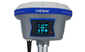
IMU-RTK receiver
Increases GNSS availability and reliability
Photo: CHC Navigation
The i90 IMU-RTK GNSS series receiver is designed to dramatically increase GNSS real-time kinematic (RTK) availability and reliability. The i90 is powered by the company’s latest inertial measurement unit (IMU) and RTK technology to provide robust and accurate GNSS positioning in any circumstances. Unlike standard micro-electro-mechanical (MEMS)-based GNSS receivers, the i90 GNSS IMU-RTK combines a high-end calibration and interference-free IMU sensor with a state-of-the-art GNSS RTK engine and advanced GNSS tracking capabilities. The i90 is designed to increase the productivity and reliability of survey projects, with no complicated calibration process, rotation, leveling or accessories are necessary. A few meters’ walk will initialize the i90 internal IMU sensor and enable RTK survey in difficult field environments. The i90 GNSS automatic pole-tilt compensation boosts survey and stakeout speed by up to 20%.
Both accurate and rugged for machine control, logistics
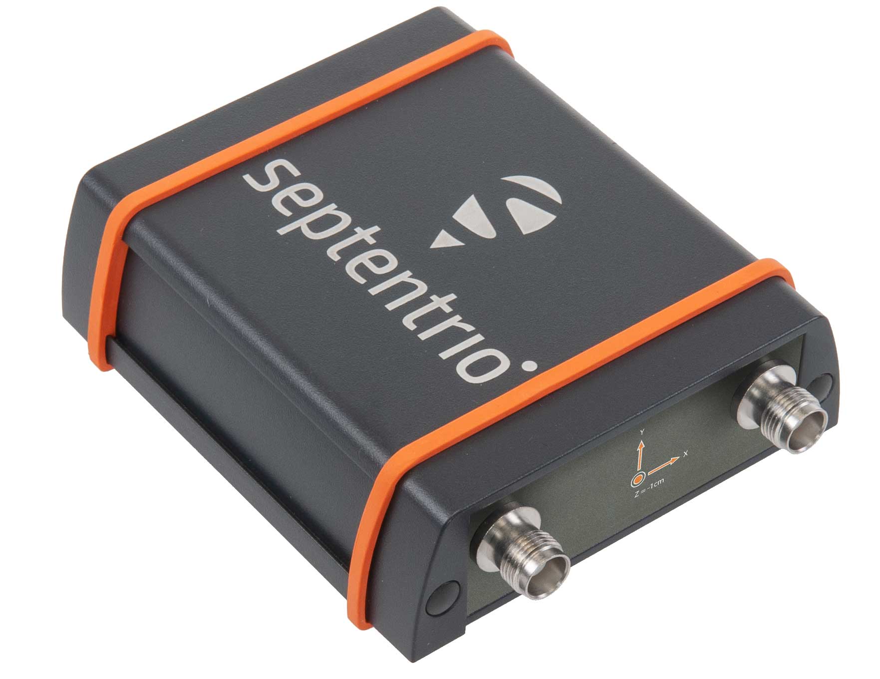
The AsteRX-SBi has a rugged housing, making it suitable for machine control and other outdoor uses. (Photo: Septentrio)
Septentrio has expanded its GNSS/INS portfolio with the AsteRx SBi, a new housed GNSS/INS receiver. The ruggedized AsteRx SBi fuses high-accuracy GPS/GNSS with a high-performance inertial sensor to provide reliable positioning and 3D orientation for machine control and logistic applications. Within its rugged, waterproof enclosure, a high-performance GPS/GNSS is coupled with an industrial-grade inertial sensor to provide high-accuracy, reliable positioning and 3D orientation (heading, pitch, roll). Offering the flexibility of either single or dual antenna, the AsteRx SBi is designed for quick and easy integration into any machine monitoring or control system. Reliable location and 3D orientation data is streamed with a high update rate and constant low latency. Septentrio’s reliable centimeter-level positioning is based on true multi-frequency, multi-constellation GNSS (GPS, GLONASS, Galileo, BeiDou, QZSS) technology.
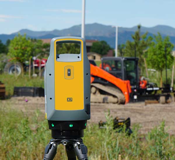
The Trimble X7 laser scanning system is designed for surveying, construction, industrial and forensic applications. It enables professionals to quickly and easily capture precise 3D scanning data to produce high-quality deliverables. The X7 features Trimble X-Drive technology, survey-grade self-leveling and a smart calibration system. It integrates streamlined workflows to provide automatic registration of point-cloud data in the field with Trimble Registration Assist, bringing scans together through self-leveling inertial measurement unit technologies and cloud-based software.
The Bluesky MetroVista range includes high-resolution imagery combined with high-accuracy, wide-scale 3D models. (Image: Bluesky)
The MetroVista city mapping service for Europe incorporates the Leica CityMapper hybrid airborne sensor designed for 3D city modeling and urban mapping. The sensor includes a vertical camera and survey-grade oblique cameras, and incorporates lidar to accurately collect elevation and infrared data. The MetroVista range includes high-resolution imagery combined with high-accuracy, wide-scale 3D models. CityMapper has already been used to capture MetroVista data for cities across the United Kingdom, including London, Manchester, Newcastle and Bristol.
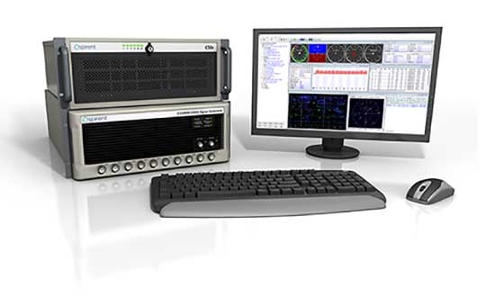
The enhanced GSS9000 series GNSS constellation simulator has been updated to provide significantly improved capability, flexibility and performance to meet the test needs of high-performance navigation systems. It doubles the number of supported channels (320 in a single chassis) while maintaining its full performance specification in key areas such as signal iteration rate and low latency under maximum signal dynamics. These attributes, together with the ability to produce a comprehensive range of emulated multi-GNSS, multi-frequency RF signals, enables full and future-proofed testing of advanced applications. Greater signal flexibility is also built into the enhanced GSS9000 through its open application program interface (API) and flexible architecture. This delivers a highly sophisticated arbitrary waveform generator (AWG) capability.
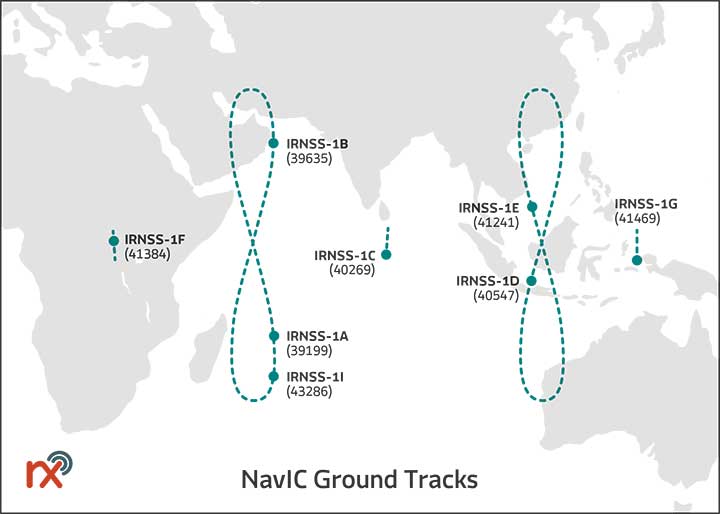
Rx Networks has added NavIC constellation support to its real-time and predicted-assistance data service. The company’s technology partners — semiconductor vendors, mass-market mobile device manufacturers and network operators — now have global support for all satellite navigation systems and L1 satellite-based augmentation systems (SBAS) for any region around the world. Used daily by more than two billion devices, Rx Networks data is delivered via ephemeris in RINEX and via the Location.io interface, with predictions in SP3. Predictions for NavIC via the Location.io platform will be added in the first quarter of 2020.
Endura micro-electro-mechanical system (MEMS) timing solutions are designed for aerospace and defense applications including precision GNSS. They provide high performance in harsh conditions such as severe shock, vibration and extreme temperature. SiTime offers customers 5 million possible part numbers that can be created from 17 programmable products. Solutions accommodate 4 parts per trillion per g force of acceleration (50 times better than quartz); support for –55° C and +125° C operation; timing specifications conforming to MIL-PRF-55310; and Endura Super-TCXOs (temperature compensated oscillators) for use in GNSS applications.
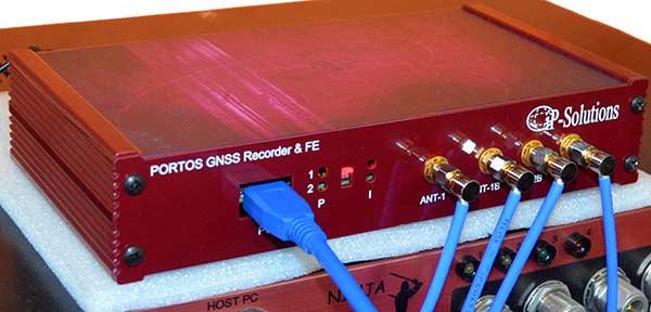
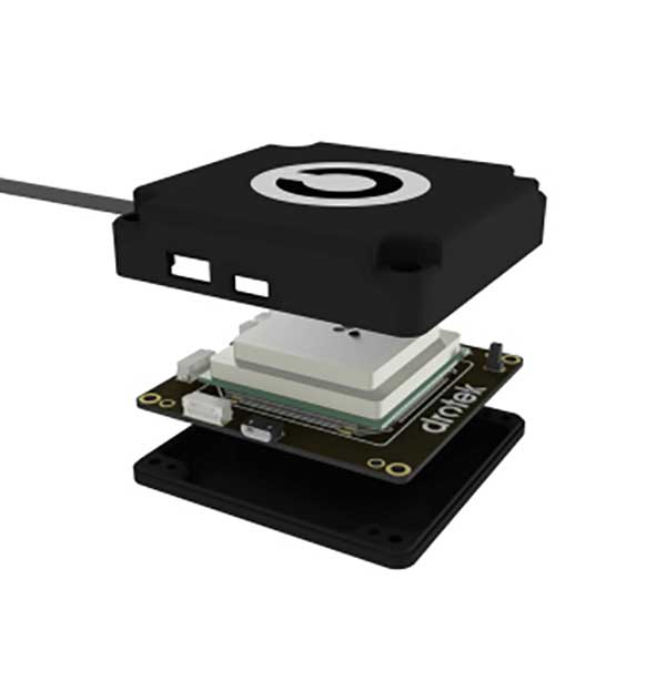
Portos Team paired with the Ninja. (Photo: IP-Solutions)
Portos Team is a new GNSS RF signal record-and-playback system. It can record and play back — or simulate —multi-frequency, multi-system GNSS signals when paired with the company’s Replicator. It can do the same for CRPA signals when paired with the company’s Ninja. The Portos itself can also operate as multi-frequency or CRPA front end for a GNSS software receiver.
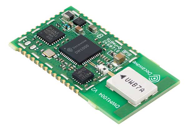
The DWM1004 module targets time difference of arrival (TDoA) tag applications that require years of battery life and a compact design. Based on the DW1000 chipset, the DWM1004C offers high-accuracy, real-time-location capability with a 6.8-Mbps data rate. It delivers more than five years of battery life. Real-time location systems (RTLS) enable managers to have a real-time view of their operations through data collected from connected objects such as tools, pallets, forklifts, badges and collars. The DW1000 is immune to multipath fading, with 2-centimeter precision in indoor environments.
The F9P Sirius RTK GNSS rover is designed to be mounted on a moving vehicle. The u-blox ZED-F9P module inside provides 1-cm position accuracy, a convergence time under 10 seconds and a navigation update rate up to 20 Hz. The rover has a built-in active antenna patch. It receives GPS, Galileo, Beidou and GLONASS signals, providing additional accuracy. It is designed to fit most setup designs as well as integrate easily into a vehicle. Its six-pin JST-GH connector makes it plug-and-play with the Pixhawk Pro 3 autopilot.
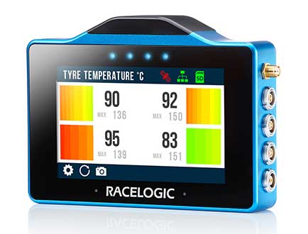
The VBOX Touch is a highly flexible GNSS datalogger with enhanced accuracy. The powerful hardware can be used diverse automotive tests such as acceleration, braking, speed verification, tire temperature monitoring, lap-timing and durability. The VBOX Touch comes preloaded with a sophisticated performance application that covers common use cases; applications can be downloaded from an online library. Racelogic can also write custom Python scripts based on customer requirements.
The LG69T GNSS module is an automotive-grade dual-band high-precision GNSS module that integrates dead-reckoning (DR) and real-time kinematic (RTK) technologies. The module facilitates open-sky positioning performance with an accuracy of up to 10 centimeters. It supports next-generation precision positioning capabilities for smart vehicles and autonomous driving scenarios. The LG69T module is based on ST’s STA8100GA, the latest automotive-grade dual-frequency positioning chip with 80 tracking channels and four rapid-acquisition channels compatible with GPS, BeiDou, Galileo, Navic and QZSS. The AEC-Q100-qualified dual-band module integrates multi-band RTK technology for centimeter-level accuracy. The LG69T module’s dead-reckoning capabilities feature an integrated inertial measurement unit (IMU) that provides continuous high-precision positioning.
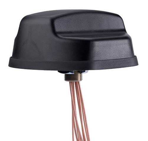
The Coach II antenna with GNSS L1/L2/L5 is designed to provide greater precision and reliability for advanced rail communications systems, enabling next-generation positive train control (PTC) and passenger Wi-Fi. The Coach II features global multi-GNSS compatibility, dual-port 4G LTE / sub-6 GHz 5G NR and 802.11ac Wi-Fi / Bluetooth connectivity. It is AAR compliant for railway applications and is IP67-rated.
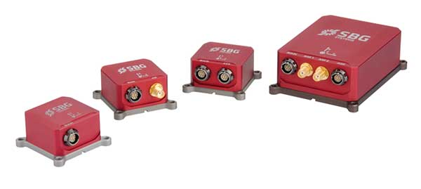
Includes new automotive package for Ellipse GNSS/IMU products
Photo: SBG Systems
New features have been added to the Ellipse product line with firmware update version 1.7. The update better answers needs of the autonomous testing and driving markets such as a CAN odometer. Users now have the choice to connect an external odometer (DMI) with pulses or use their car odometer with velocity information. New outputs include body velocity and slip angle, which calculate the drift angle between the vehicle’s assumed trajectory and its actual trajectory. For precision applications as well as low dynamics and reduced warm-up time, the new firmware allows users to run the Ellipse Kalman filter with no lever-arm estimation. This will ensure centimeter pass-to-pass accuracy for real-time kinematic (RTK) applications and allow operation in lower dynamics while reducing warm-up time. The firmware update also provides new features for advanced marine applications.
GNSS and inertial navigation sensors are meeting the challenges of extreme conditions, from freezing Arctic ice to the edges of steaming volcanoes, from high-speed aircraft over cities to the subways under them. Even beyond, into deep space.
IN THE ARCTIC
Wave Buoys Help Study Arctic Climate Change
Where the edge of Arctic ice transitions to open water, towering seas are smashing sea ice into melting pieces, with far-flung effects on climate and nature. Over recent decades, the Arctic has warmed more than any other region, leading to a significant reduction in sea ice volume. The combination of increased ice-free area and more mobile ice cover has led to the emergence of a seasonal marginal ice zone (MIZ) in the Beaufort Sea, north of Prudhoe Bay, Alaska.
The United States Office of Naval Research conducted a five-year study of the MIZ, which included intense field work in the freezing Arctic sea. Here, the ice is vulnerable to ocean surface waves that form in the open water, resulting from strong winds and frequent storms. Also studied were in-ice waves, where ice and water clash. The goal was to understand how both factors impact the ice floe melting.
The MIZ lies in the subarctic seas in winter and transitions into the interior of the Arctic Basin in summer. To investigate the MIZ’s dynamics, ONR engaged an international program of observations and simulations using several autonomous systems, including wave buoys. The wave buoys — officially designated the autonomous ocean flux buoys — integrate SBG Systems’ miniature inertial sensors.
The MIZ study comprised an international team of scientists from more than a dozen organizations.
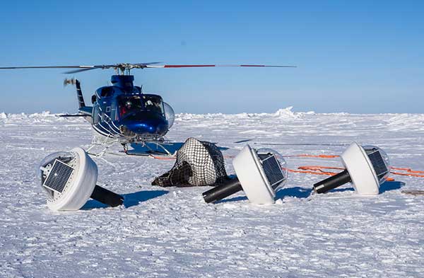
Buoys for All Seasons. The program included 20 buoys deployed in the summer, and five in the winter, to quantify open ocean and in-ice wave characteristics and evolution. “We needed a very rapid and cost-effective solution to measuring directional wave spectra in the ocean,” said Martin Doble, oceanographer at the French UPMC School and member of the research program. “Time to deployment was very short, so an integrated solution, giving us good heave numbers straight out of the box, was essential. Delivery time of the units was also critical.”
Drilled into the ice, the summer buoys were powered with solar panels and equipped with SBG Systems’ IG-500A miniature attitude and heading reference system to detect both distant and near-wave effects on the local ice floe. Once the ice melted, the summer buoys continued to measure open ocean characteristics.
Five winter buoys were installed on the ice. These buoys were made of aluminum for better resistance and contained enough battery power to keep them going through the dark winter months. Every buoy also contained processing and control electronics, an SD card, a GPS receiver and an Iridium satellite modem and antennas to transmit the recorded data to its base station. Both summer and winter data from the buoys were used to quantify the wave attenuation rate.
Winter buoy installed on an ice floe. (Photo: SBG Systems)
By measuring the waves and ice, the buoys help scientists understand how waves are approaching and breaking up the sea ice. When winter approaches and ice begins to refreeze, the buoys help show how the waves interact with the ice as the temperatures change.
Calibration. The IG-500A inertial sensors were used for wave height and direction. IG-500A measures in real time the roll, pitch, heading (accurate to 0.35°) and heave (accurate to 10 centimeters). Every sensor is calibrated for bias, linearity, gain, misalignment, cross-axis and gyro-g from –40° to +85°C. The calibration is key to enabling the sensors to provide reliable data in the harsh environment.
Doble said the units were reliable, with no failures in the harsh Arctic conditions. They ran continuously for more than a year without requiring power cycling, and “the numbers look good, giving clear results.”
The data is helping researchers understand the physics that control sea ice breakup and melt in and around the ice edge. “We have this amazing picture of the ocean, atmosphere, and ice going from the fully frozen period in March to meltdown and breakup right through to freeze-up,” said Craig Lee of the University of Washington’s Applied Physics Laboratory.
The IG-500A sensors also delivered heave measurement, important for instrumented ocean buoys. During the project, SBG Systems released the Ellipse Series, and the new line replaced the IG-500 series. More accurate in attitude and more reliable (with an IP68 rating) for the same budget, the new miniature inertial sensors now provide a heave measurement that automatically adjusts to the wave period, resulting in higher performance.
Clear differences were measured between surface wave activity outside of the ice, and then moving into the ice, with huge attenuation as the waves enter the ice and die back quickly.
Current Arctic Program. Following the close of the MIZ project in 2015, the ONR launched a new project for 2016–2020, the Stratified Ocean Dynamics in the Arctic (SODA). SODA is also taking place in the Beaufort Sea, and is using the autonomous ocean flux buoys. The buoys are now equipped with SBG’s Ellipse-A sensors.
Why the Arctic Matters
“There’s no question that the Arctic sea ice extent is decreasing,” said Martin Jeffries, program officer for the ONR Arctic and Global Prediction Program. “Multiple sources of data — autonomous underwater gliders, ice-measuring buoys and satellite images of the marginal ice zone — were used to help understand why the ice is retreating.”
The implications for the U.S. Navy, and the world, are significant. If there were no sea ice in the Arctic at the end of summer, that would mean that the Arctic Ocean would, until the winter ice came in, be completely open — something unprecedented in living memory, Jeffries noted.
Naval leaders have made it clear that understanding a changing Arctic is essential for the Navy to be prepared to respond effectively to future needs.
“[T]he opening of the Arctic Ocean has important national security implications as well as significant impacts on the U.S. Navy’s required future capabilities,” said then Chief of Naval Operations Admiral Jonathan Greenert, in his introduction to the U.S. Navy Arctic Roadmap, 2014–2030, published in 2014. “The United States has a history of maritime homeland security and homeland defense concerns in the Arctic Region […] .”
In the period between 2007 and 2014, satellites recorded the eight lowest sea ice levels ever. A key goal of the MIZ and SODA programs is to use the new data collected to make better predictive computer models — ensuring safer operations for not only naval vessels, but also anticipated increased sea traffic by shipping and fishing industries; oil, gas and mining companies; and tourism operations.
Much of the data coming in to Arctic scientists is now from improved sensors, with greater ability to survive the harsh weather and ocean conditions.
Inside the Ellipse
Alexis Guinamard, chief technology officer of SBG Systems, described to GPS World the company’s most advanced sensor for extreme environments.
“Of course we have more precise sensors like Ekinox, Apogee or even Horizon, for ‘extreme’ precision. But for extreme environments, the more appropriate sensor line is the Ellipse series,” Guinamard said. “There are several key parameters that make them better for this kind of environment.”
Those features include a high-temperature calibration range, from –40°C to +85°C, which enables the sensors to operate at the same performance level in the most extreme temperature environments.
“While typical entry-level or industrial-grade sensors only provide a room temperature or basic temperature calibration, we have developed a calibration procedure used for both survey-grade and industrial-grade sensors using a precision two-axis rotary table with temperature chamber,” Guinamard said. “An advanced thermal modeling minimizes the calibration error over the full temperature range.”
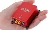
Ellipse-D dual-antenna mini INS/GNSS. (Photo: SBG Systems)
The sensors work in highly dynamic and vibrating environments because their gyros operate well, changing position up to 900° per second. Similarly, their accelerometers can reach up to 40 g, with excellent behavior in vibrating environments. “We can typically install our sensors directly on the chassis of the vehicle, while lower grade sensors may require specific dampers that are complex to design and make it difficult to precisely align the sensor,” Guinamard said.
A GNSS interference-mitigation capability enables the sensors to perform in challenging GNSS environments.
With the Ellipse-D, high latitude operation is possible because it provides a dual-antenna heading that is insensitive to higher latitudes, Guinamard explained.
Saltwater-Proof. SBG Systems sensors typically have waterproof (IP68) enclosures that can deal with harsh conditions and sustain exposure to saltwater for a limited period of time. For long exposure to salt water, the company offers specific titanium enclosures. For instance, its Navsight series has a saltwater-proof inertial measurement unit.
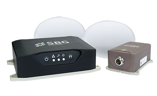
Navsight marine solution. (Photo: SBG Systems)
The Navsight Marine Solution is a motion and navigation solution for hydrographers available as a motion reference unit (MRU), as an inertial navigation solution (INS) with embedded GNSS, and as an INS using a third-party GNSS receiver.
Navsight can be outfitted for demanding shallow- or deep-water environments to survey highly dense areas (bridges and buildings), as well as applications where only a single antenna can be used.
With the addition of the Horizon inertial measurement unit (IMU) to the Navsight line in January, which joined the Ekinox and Apogee IMUs, the line is suitable for large hydrographic vessels surveying harsh environments. The Horizon IMU is based on a closed-loop fiber-optic gyro (FOG) technology that enables ultra-low bias and noise levels, allowing robust and consistent performance.
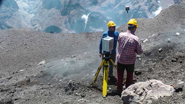
Dust, noxious gas and loose rock near the summit makes volcanic surveying especially challenging. (Photo: Trimble)
AT VOLCANO’S EDGE
GNSS Tracks Magma on Mount Etna
Scientists seeking to better understand volcanoes are using GNSS to investigate one of the most active in the world.
Mount Etna, in eastern Sicily, Italy, has been erupting for hundreds of thousands of years. The constant activity makes it a popular tourist attraction — smoke often billows from the mountain and fiery lava spews down its sides.
Researchers flock to Mount Etna, too, to study the movement of magma — the hot fluid beneath the Earth’s surface from which rocks are formed when cooled.
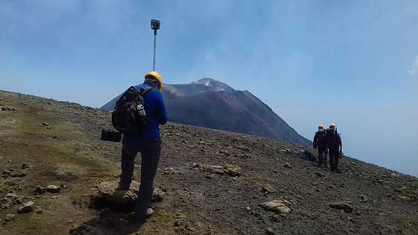
To measure the vertical gradients of gravity on Mount Etna’s slopes and summit craters, geophysicists from Slovakia and Italy teamed up on a field campaign during which they used high-accuracy GNSS positioning with emphasis on accurate height measurements to collect gravimetry and topographic information.
The extreme environment and spotty cellular coverage on Mount Etna made using GNSS with real-time kinematic (RTK) or virtual reference station (VRS) a challenge. The geophysicists used the Trimble CenterPoint RTX correction service and Trimble R10 GNSS receivers to ensure reliable GNSS performance.
“On many points, especially the higher part of the volcano, Internet signals were poor or [there were] none at all,” said Juraj Papčo, a geodesist with the Earth Science Institute of the Slovak Academy of Sciences. “Only by using RTX were we able to collect real-time data. It performed well in higher elevations and difficult conditions.”
The project teams also used Trimble RTX to navigate to locations where they needed measurements. At each station, they collected static and real-time positions and later compared post-processed results with the real-time positions.
Dust, noxious gas and loose rock made approaching the summit especially challenging. Trimble RTX helped the Slovak-Italian team of geophysicists better understand volcanoes and anticipate volcanic events.
Researchers used high-accuracy GNSS positioning to collect gravimetry and topographic information. (Photo: Trimble)Prisms affixed to the track enable measurement of change and structural movement. (Photo: Topcon)
UNDER A METROPOLIS
Harsh Construction Environment Monitored
Deep beneath Paris, work is underway to expand the Metro, the city’s rapid transit system. The Grand Paris Express project encompasses a 200-kilometer-long network of railway lines — mostly underground — that will link the suburbs to the city.
The contractor responsible for monitoring construction of the first stage of the project’s infrastructure, Cementys, is using more than 100 instruments from Topcon’s MS series of robotic total stations because they can withstand the harsh construction environment.
Monitoring structural movement across the network is critical; the goal is to protect the surrounding Parisian structures and the people who live and work in them. Use of the monitors also ensures that the expensive equipment used on the project is not stolen.
Topcon’s MS Series robotic total stations continuously measure the angles and distances of prisms fixed to structures. As a result, site engineers know immediately when measurement change and structural movement occurs. The technology also includes Matrix Detection software to help increase the measurement system’s speed and accuracy. The company’s TSshield integrated security software, standard on all its total stations, provides remote locking and location positioning data to within 100 meters, depending on GPS and cellular coverage.
“We have been able to integrate this open technology perfectly into our global data management system, which also includes optical fibers sensors, vibrating wire sensors, and others,” said Cementys CEO Vincent Lamour.
Construction of the Grand Paris Express project is taking places in stages and is expected to be complete in 2030.
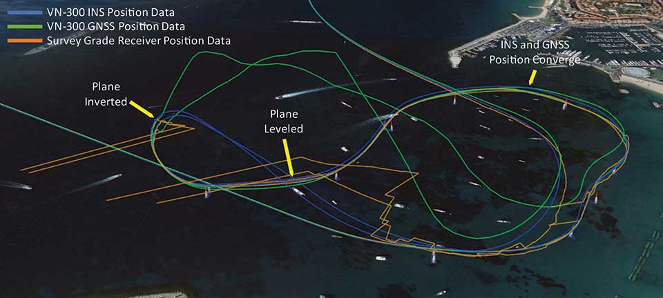
Photo:Position tracks from two laps of the race show that when the plane inverts and starts to track the reflected signal, the VN-300 GNSS/INS (blue trace) reverts to free inertial navigation and propagates the position based on inertial data. The trace follows a smooth trajectory through the next air gate until the GNSS data converges with the INS position. (Image: Google Earth with VectorNav Data)
ABOVE THE SEA
Flying High with Augmented Reality
The 2018 Red Bull Air Race World Championship in Cannes, France, made it easier for fans to follow along. Though pilots race one at a time, the new “Ghost Plane” augmented reality imagery provided fans with a real-time representation of each pilot’s flight, which challenges their speed, precision and skill maneuvering lightweight racing planes.
The Ghost Plane is driven by onboard telemetry data gathered during flight. For a pilot’s run to be accurately represented, the onboard telemetry system has to track position, velocity and attitude (yaw, pitch and roll) through high-dynamic maneuvers and in challenging environmental conditions.
While every Red Bull Air Race track layout is different, they all include a difficult vertical turning maneuver (VTM), where pilots pass through a gate and turn 180 degrees to reverse course quickly without exceeding the g limit.
Each plane is fitted with several GNSS receivers to track the plane, but dynamic maneuvers made during the race rapidly changes which satellites the GNSS receiver can track, which typically results in a loss of position fix.
To further increase the challenge for the telemetry systems, races are commonly held over water, which can reflect GNSS signals and create significant multipath errors at low altitudes. During the VTM, the plane can experience 300°/second angular rates and 12-g accelerations, during which GNSS tracking is typically lost because the antennas no longer point to the sky.
To make the Ghost Planes possible, a VectorNav VN-300 dual-antenna GNSS/INS (inertial navigation system) couples gyroscope and accelerometer data to propagate position and velocity estimates during loss of GNSS measurements through maneuvers such as the VTM.
The VN-300 combines two GNSS receivers with a 9-axis inertial measurement unit (IMU). It couples acceleration and angular rates from the IMU with position and velocity data from the receiver using a quaternion based Extended Kalman Filter (EKF). VectorNav algorithms work in conjunction with the state estimation filter, making the VN-300 more robust and intelligent, and enabling it to reject poor GNSS data and perform accurately in high-dynamic maneuvers and challenging operating conditions.
NEW EQUIPMENT
Antenna Designed for Challenging Environments
CHC Navigation’s latest GNSS antenna is an example of a product designed specifically for harsh environments.
AT311T antenna. (Photo: CHC Navigation)
The heavy-duty CHCNAV AT311T is designed for demanding applications subject to shocks and vibrations. With advanced filtering and robust signal tracking, it provides survey-grade GNSS signals to enhance position reliability for marine applications, machine control, precision agriculture and industrial automation.
Features include multi-constellation GNSS tracking using GPS, GLONASS, BeiDou, Galileo, QZSS, IRNSS and SBAS. Its IP68 water-resistant design makes it safe to use in extreme conditions with a wide temperature range (–40°C to +85°C). Its internal stacked structure enhances performance in high-interference environments, and the 40-dB signal gains, advanced signal filtering and multipath rejection design provide superior and robust GNSS signal tracking in challenging surroundings.
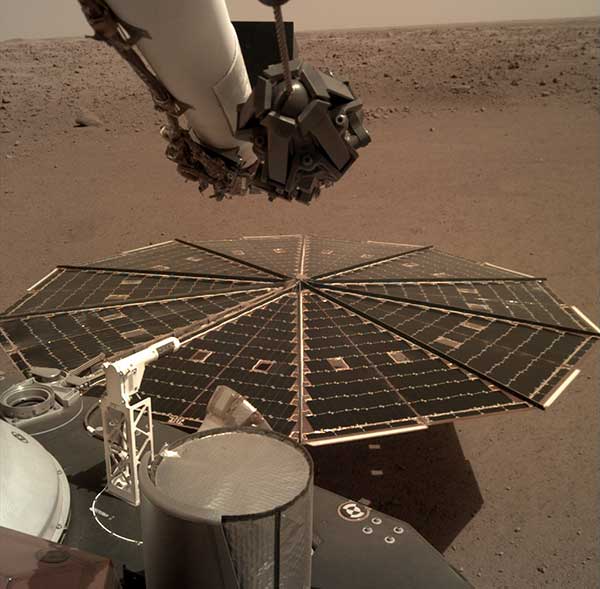
One of the two solar arrays on the InSight lander dominates this view of the plain of Elysium Planum, taken Dec. 4, 2018. (Image: NASA/JPL-Caltech)
IN OUTER SPACE
Exploring Beyond Earth
While GNSS isn’t useful on the surface of Mars, inertial navigation is a key technology for exploration of the red planet. For instance, the Northrop Grumman LN-200S sensor guided the Mars Opportunity rover, which explored Mars for 15 years until a storm struck in June 2018.
The LN 200S sensed acceleration and angular motion, with its data output used by the rover’s control systems for guidance.
The hermetically sealed unit, suitable for planetary and asteroid probes, helped position the rover’s antennae to relay photos and data to satellites. Opportunity beamed back 187,000 raw images, according to NASA.
Because IMUs don’t depend on satellites, they work well for deep space missions, Honeywell explained in a press release.
In November 2018, NASA’s InSight spacecraft landed on Mars to study the interior with a heat probe and listen for marsquakes with a seismometer. Aboard was Honeywell’s Miniature Inertial Measurement Unit (MIMU), an IMU that has been a part of Lockheed Martin’s Mars satellites and landers since 1998.
The MIMU is a three-axis strapdown device specifically designed for the satellite and deep-space-probe market (more than 500 MIMUs have been deployed throughout the solar system). It uses ring laser gyros to help control and stabilize a spacecraft during entry, descent and landing, as well as maintain orbit and payload orientation. The radiation-hardened design supports 15-year missions.
A famous quote applies to almost everything in our lives: “There is nothing permanent except change.”
This well-known saying is generally credited to the Greek philosopher Heraclitus (500 B.C.E.), although many historians and philosophy experts tend to agree the quote is a combination of many topics found in writings by Heraclitus.
However the quote came to be, it aptly describes the world we live in; especially now with lightspeed advancements in technology. Change is markedly evident in today’s surveying world, and almost no practitioner is exempt from revolutionary enhancements and necessary upgrades to stay current in our profession.
Change is on the horizon
Photo: Trimble
The upcoming NGS 2022 datum change, triggered by advancements in positional accuracies and measurement techniques, has quietly created a groundswell of questions, concern and curiosity of how and why we are at these crossroads. In my September 2019 Survey Scene article, we discussed the background behind the necessity of the upgrade and moving toward a standardized measurement unit, (the “foot”). (For purposes of this article, let’s put aside any mention of using the meter/metric system; the U.S. went down that road in the late 1970s / early 1980s, yet crashed and burned upon implementation. I agree the meter is a more practical unit of measurement, but we need to leave that talk for another day.)
This article will be concentrating on the actual coordinate systems and how significant changes are coming for almost everyone performing surveying measurements. Yes, this means all those construction-based users of GNSS receivers and total stations performing pre-, in-progress and post- construction tasks. Our coordinate world will be turning upside down but, in this case, it will be changes for the good.
Origins of X/Y (otherwise known as Northing/Easting)
We have another philosopher to credit for the concept of coordinate geometry; he is the French scientist Rene Descartes (1596-1650) who was heavily influenced by Plato.
While he may be more well known for his famous quote “I think, therefore I am,” Descartes created what is believed to be the first graphical depiction of geometrical expressions and assigning coordinate values to the results; hence the background behind “Cartesian coordinates.” It is this coordinate system that was utilized by late 1800s/early 1900s surveyors who began using this system to create small networks within urban settings, including New York City, Cincinnati and Atlanta.
As economic expansion continued through the Great Depression and beyond, the need for larger survey networks became more evident. The first state plane coordinate system (SPCS) began in North Carolina in 1933-34 with more states quickly falling in behind them. The main force behind this effort was the U.S. Coastal & Geodetic Survey (now known as National Geodetic Survey), as they utilized many surveyors and engineers that were unemployed due to the Stock Market Crash of 1929 and Great Depression. Technology for the era was limited to theodolites and steel tapes, with most computations being based upon triangulation.
Enter the Electronic Age of surveying
“Big Red” Geodimeter 4D (Photo: National Oceanic and Atmospheric Administration)
Positional and measurement technology remained stagnant until the 1950s and 1960s with the introduction of the electronic distance meter (EDM). Longer measurements could be made with increased accuracy and helped expand our coordinate system capabilities.
These enhancements also led to faster expansion of a nationwide highway system (championed by President Dwight Eisenhower) by simply surveying more efficiently. It is along these highway corridors that state plane coordinate systems were expanded into remote areas and used to verify fractured SPC systems created through solar and/or astronomical means. While positional values at common monuments were found to have significant differences by today’s standards, most error was distributed throughout the network.
Because of the work necessary to complete a survey using a SPCS, it was not practical for any non-governmental project to attempt tying into a known system. Fundamental use of coordinate geometry (CoGo) typically utilized a project base point with a low assumed positional value, (i.e. northing of 1,000, easting of 2,000).
Most surveyors used the same coordinate values for each project and did not have any positional relationship between their projects. While the field portion of the project took a significant amount of time to traverse and collect, the office calculations and manual drafting were also tedious and time-consuming tasks.
Prior to the introduction of the handheld calculator in the early 1970s, traverse computations were completed manually using sine/cosine/tangent tables, traverse adjustment (i.e. compass, transit and Bowditch rule) and double distance meridian (DMD) methods. Even as the programmable calculator became the computation method of choice, regularly producing survey data in SPCS was still years away.
Along with the electronic theodolite and the personal computer with computation software, the introduction of the data collector quietly revolutionized the amount of data that could be stored and efficiently plotted for surveys. But even with the increased efficiencies, there was one big drawback to utilizing this electronic data collection with SPCS; most hardware was limited to values and significant figures not acceptable to using large coordinate values. Some tried truncating SPCS values but often found the trouble not worth the effort, not to mention having projects large enough to be affected by grid-to-ground scale factors (another topic for another day).
Fast forward to the 1980s and the introduction of ultimate surveying black box, the GPS receiver. Positional accuracy through static GPS sessions was now better than ever and allowed surveyors to cover greater distances in shorter time periods. It was the implementation of the GPS receiver (and subsequent reduction in cost of entry for its use) that allowed the surveyor to embrace the state plane coordinate system more than ever. Also addressed with the new technology was the ability for the data collector to handle larger coordinate values with increased significant figures.
As RTK and subsequent RTN systems have allowed for more efficient use of GNSS technology, the surveying profession has now overwhelmed the existing monument network and exposed the deficiencies of NAD83 and our various SPCS zones nationwide. NGS has done an excellent job for many years refining and adjusting the national datums (both horizontal and vertical) by augmenting the systems with new data and “turning the screws” as deemed necessary to provide a reliable network.
If it is not broken, why fix it?
The existing SPCS zones and overall NAD83 system works well but we will need to circle back to the quote in the opening paragraph: “There is nothing permanent except change.”
Research, not just completed by NGS but many other respected agencies and laboratories worldwide, has shown that our existing datums have significant flaws due to many factors. These factors include, but are not limited to, tectonic plate shifting, previous survey data that doesn’t meet today’s positional and measurement standards, and limitations in terrestrial measurements.
We are overdue for an upgrade to the national system and design of new policies and procedures has taken time and lots of hard work. NGS has created a new framework that will adapt to the changing needs of a state and/or regional authority.
But what does this mean for the surveyor, the contractor and anyone else in the geospatial world that uses state plane coordinates for the basis of data?
Image: National Geodetic Survey (Michael Dennis)
As discussed in the last article, NGS has been busy creating a new framework with a proposed implementation of 2022-2023. While NGS is creating the specifications, policies and procedures for the new system, it will be up to each state to decide if they want to keep their existing SPCS zones, change to a new scheme, and/or request that additional smaller zones be included for consideration. NGS, in keeping with existing policy, will work with each state to update their SPC definitions, but only if the state engages NGS during the setup period. Otherwise, NGS will apply the new datum specification to the existing zone(s).
What does this mean to the everyday surveyor?
For an example on how a state can revise their SPCS, let’s use Illinois and its plan to revise current zones. Illinois currently implements a two-zone system (East and West, lengthwise through the state) based upon a transverse Mercator projection.
For several years, GIS users and other agencies have discussed creating a single-zone system across the entire state for ease of use. Because of the size of the state and availability of RTN coverage to some remote areas, the realization of this new system has been on hold. Also, it is understood the distortion in data accuracy across a system this large would not be suitable for survey-grade applications.
Forward to 2019 and the NGS datum upgrade along with a substantial effort by several equipment manufacturers to install CORS stations across the state for broader RTN coverage (and the not-too-distant future rollout of 5G cellphone service). RTN coverage for mapping grade data collection is now readily available nearly everywhere in Illinois, so the potential of a single-zone system is now not far-fetched.
It should be noted that if Illinois decides to convert to a single-zone system, NGS will only recognize that system for future computations and documentation and the two-zone system will be scrapped. It will fall to each practitioner to convert their existing data and projects to the single-zone system if they choose to use it, but it will have some drawbacks due to the distortion of the larger system.
Image: National Geodetic Survey (Michael Dennis)
Enter the low distortion projection (LDP) system. Like other states, Illinois is discussing a potential LDP system containing 32-34 regions statewide for more accurate coordinate system development. These regions are being studied to concentrate on larger urban centers and areas where growth potential is predicted. Regions such as the Chicago, St. Louis and Peoria metropolitan areas are being highlighted for major LDP system use by not just surveyors but government and GIS analysts.
Having a coordinate system with less distortion and more accuracy can provide more reliable information for the survey but also provide more value for the residents and businesses. By concentrating the coordinate system on smaller areas through an LDP, surveyors will literally be using a communal network like their old calibrated or localized network systems of days past. The coordinates will still be large but the integrity of the data will be higher due to the reduced distortion of the system projection.
This system will also virtually eliminate the need to have a grid-to-ground scale factor because of the lack of distortion. So we will now have a large statewide system for mapping and smaller regional systems for accurate survey data going forward; sounds like a good plan, right?
Making a significant change increases our capabilities
Not to sound like a broken record, but let’s revisit the quote by Heraclitus one more time: “There is nothing permanent except change.”
Most people don’t like change, even if it is for the better. Surveyors are notoriously famous for not wanting change. Many surveyors I know would not embrace early GPS not simply due to cost, but more of not understanding how it works. They also didn’t understand how to embrace state plane coordinates and having survey data that will be compatible with their competitors. Most of those surveyors now are using it, but only because the data collectors have become more user friendly.
But why will this change be harder for most? Depending on where one is and how their state is going to adapt will affect that change. If your state is not changing any zones, they will have a -2 to +4.5-meter coordinate shift depending on where they are located. For states like Illinois and potentially changing from two zones (East and West) to a single zone and dozens of regional LDP systems, it will be a bit harder to translate all your existing survey data to the new systems if necessary.
There are several potential pitfalls in front of us if we aren’t careful. Here are a couple of scenarios to consider:
Image: National Geodetic Survey (Michael Dennis)
Understanding the general change in datum values
Converting old data to new system for reuse (additional time consideration)
For practitioners working in several LDP regions, emphasize the importance of correct zone
Software and equipment firmware updates
Older unsupported data collectors
Compatibility with current and archived GIS data
Conversions of government agency-specific data and benchmark
Major milestone dates:
Establishing a date in which all new survey data will use the new datum
Establish a date in which all design projects will utilize the new datum
Establish a date when all construction layout will utilize the new datum
These zone/LDP system changes also will be affected if your state is currently recognizing the U.S. Survey Foot and will be changing to the “foot” per my last article and ongoing NGS discussions. That change will also precipitate additional review and care for compliance of any old data to new systems.
As creatures of habit, change and adaptation moves us forward
Here’s the bottom line: We need to make this change in order to efficiently address future mapping needs and positional accuracies. Because of technology and evolution of measuring devices, we now know there are other factors that play into our coordinate systems.
As the world becomes more reliant on digital data and information, it will be critical that the right geospatial information is tied to it. There is nothing permanent except change, but change can also be for the better.
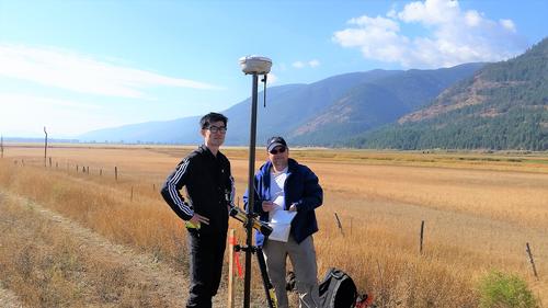


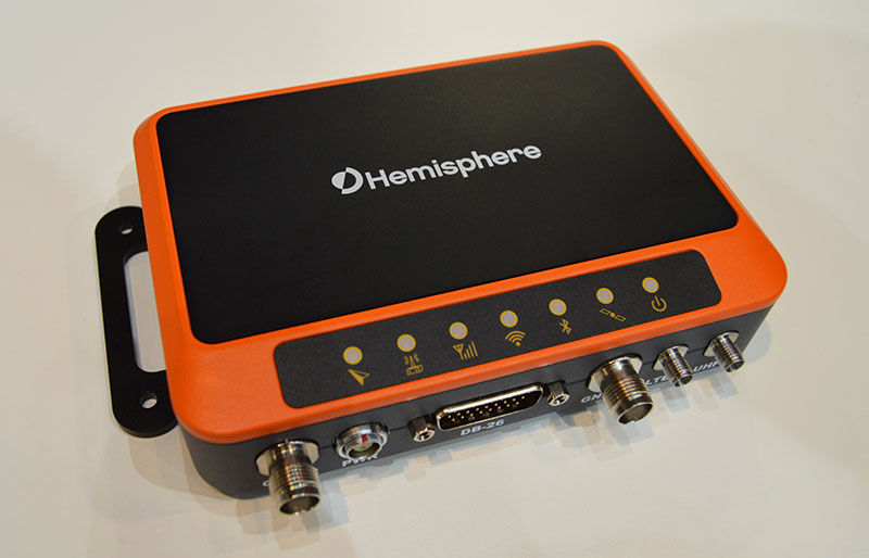
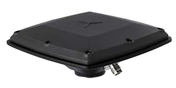
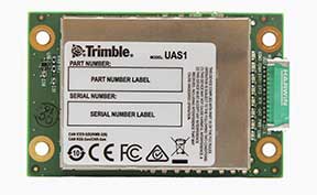
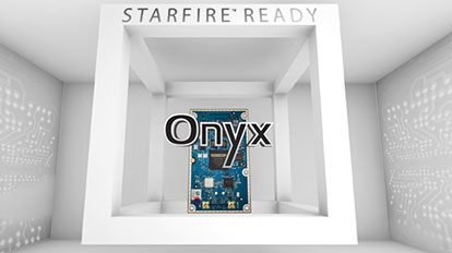
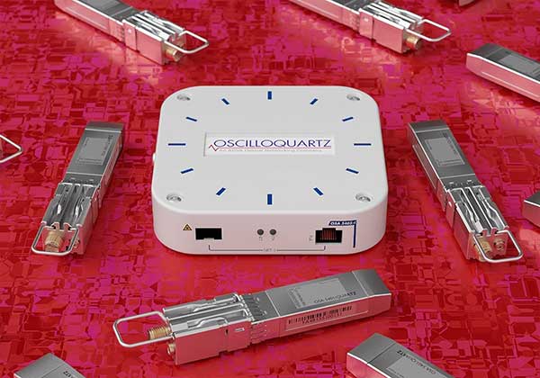
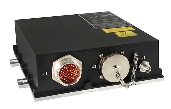
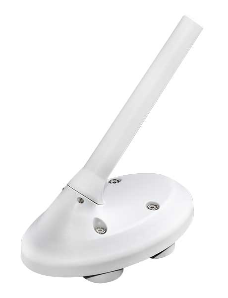
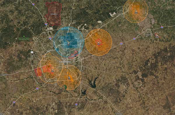
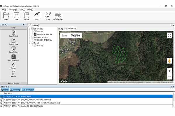

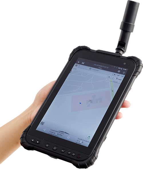
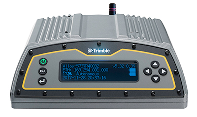

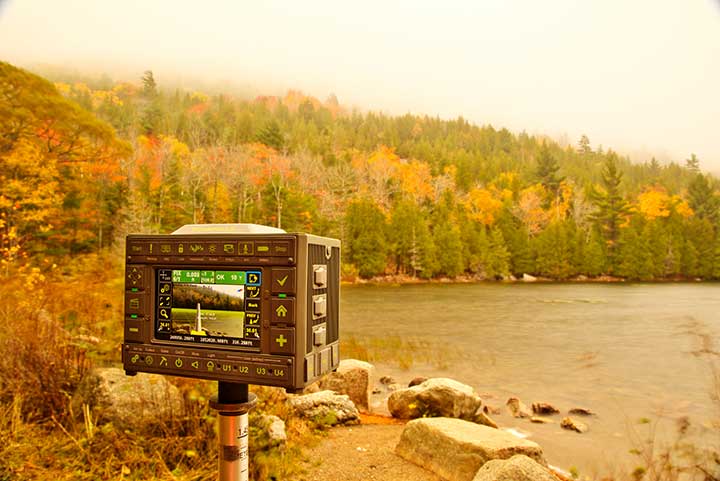
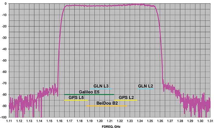
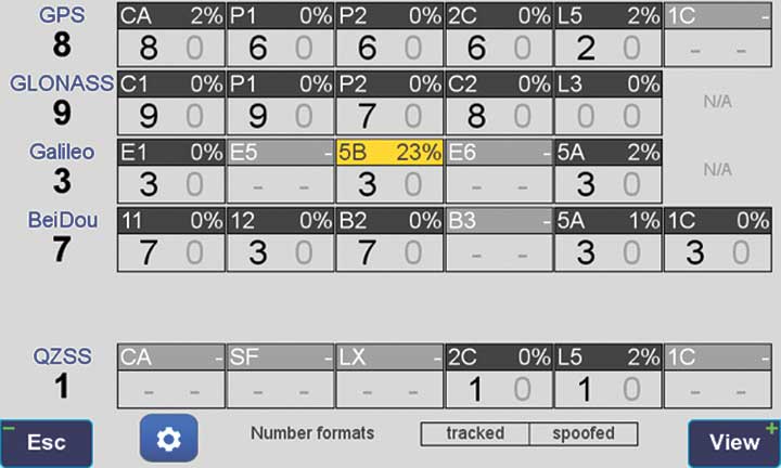
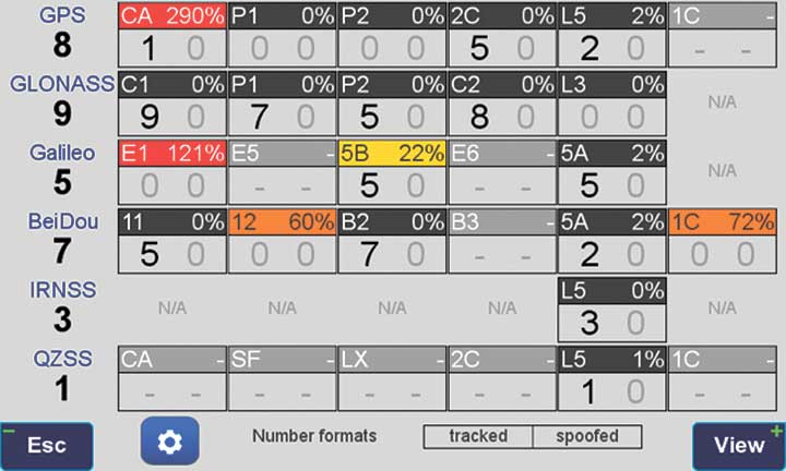
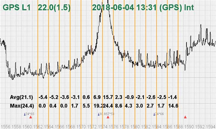
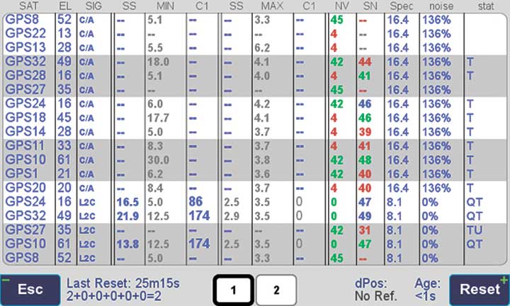
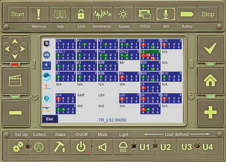
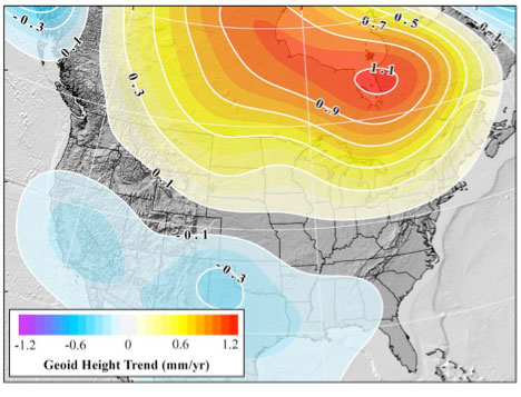
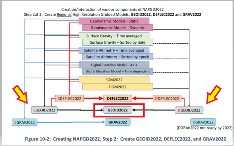
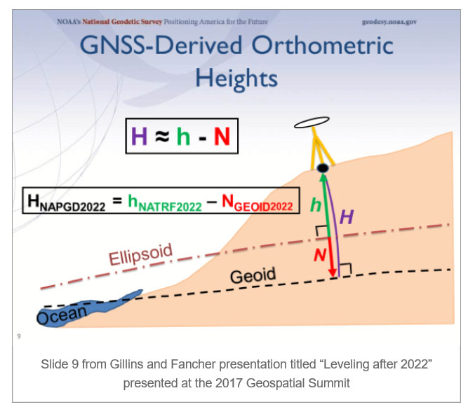
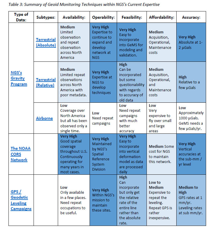
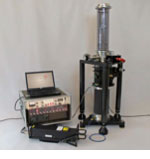
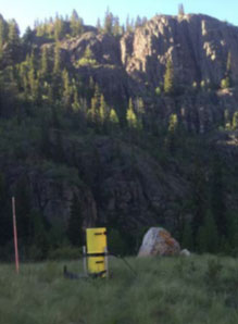
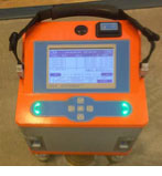
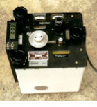
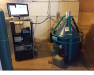
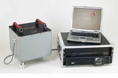
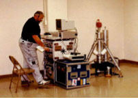
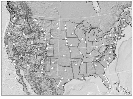
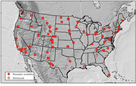
![Figure 16: Difference between NGSGN and IGSN71 AG values [mgal] (Source: National Geodetic Survey)](https://stage.globalpositioningnews.com/wp-content/uploads/zilkoski-december-2019-column-image-14.jpg)
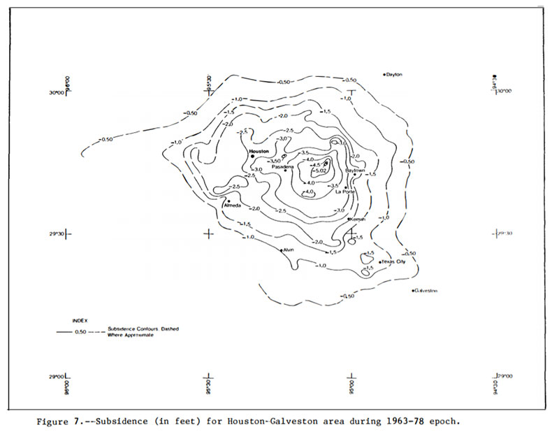
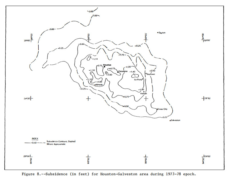
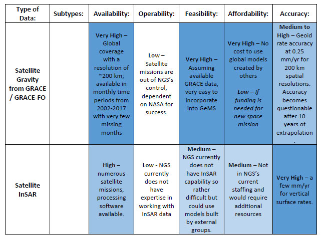
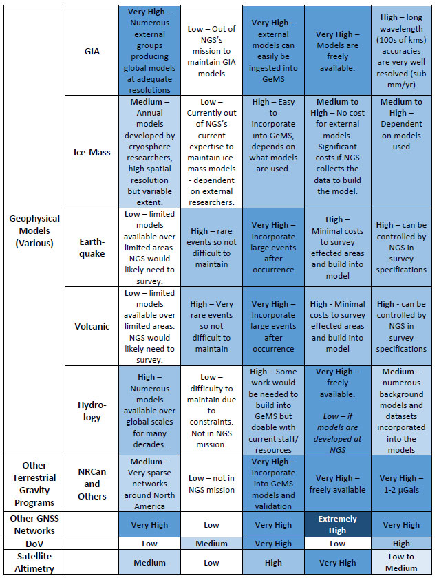
![Figure 28: GRACE Trend over Alaska from UTCSR RL06 GRACE Model [mm/yr] (Source: Figure 28 from Technical Report NOS NGS 69)](https://stage.globalpositioningnews.com/wp-content/uploads/zilkoski-december-2019-column-image-20.jpg)
![Figure 32 From Technical Report NOS NGS 69: Geoid rate over CONUS based on the GSFC mascon model [mm/yr] (Source: Figure 32 From Technical Report NOS NGS 69)](https://stage.globalpositioningnews.com/wp-content/uploads/zilkoski-december-2019-column-image-21.jpg)
![Figure 33 From Technical Report NOS NGS 69: Geoid rate over Alaska from GSFC mascon model [mm/yr] (Source: Figure 33 From Technical Report NOS NGS 69)](https://stage.globalpositioningnews.com/wp-content/uploads/zilkoski-december-2019-column-image-22.jpg)