Measurement results become quicker and more accurate with the gps 70 T’s permanent tilt compensation, resistance to magnetic interferences and calibration-free usage.
With the iCON gps 70 T, construction professionals can measure and stake out points without having to keep the pole vertical to level the bubble. According to the company, it allows the user to look at the immediate environment — for other people, machines, excavations, motor vehicles and structures — rather than on the bubble.
The combination of the latest GNSS technology and inertial measurement unit (IMU) equips the gps 70 T with its true tilt compensation. The tilt compensation extends the measurement possibilities, improves quality and accuracy of the collected data, and reduces errors.
The iCON gps 70 series is seamlessly integrated into the version 4.0 of the iCON field software. By keeping the core central interface, users will benefit from the simple-to-use workflows that require less training and avoid costly downtime.
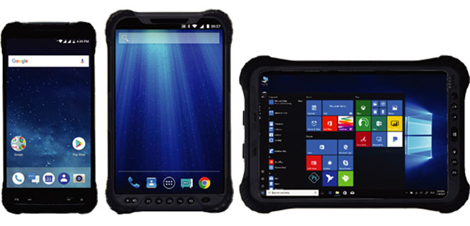
Hemisphere GNSS has launched a new UT series of GNSS-capable rugged handheld devices to support industries such as construction, survey, GIS, mapping, asset/logistics management, public safety, utilities and military.
The UT handheld devices are designed to work in the harshest environments imaginable and offer impressive and powerful feature sets.
Hemisphere made the announcement at Intermat Paris 2018, where it is exhibiting at stand 6 J 027.
The UT10 6-inch rugged phone and UT30 8-inch rugged tablet both feature Android 8.0 operating systems with Qualcomm octa-core 2.2 GHz processors, 4 GB of RAM, and 32 GB onboard storage.
The UT50 10.1-inch full-rugged tablet features the Windows 10 operating system with an Intel Core Skylake i5 processor up to 2.8 GHz, 8 GB RAM, and 128 GB of onboard storage.
According to the company, all three new UT models provide the latest high-resolution, capacitive touchscreen and direct sunlight-readable display technology for ease of visibility in all situations. The UT50 also has a 10-finger multi-touchscreen and supports wet hands and gloves operation.
The devices have dual built-in cameras. The UT10 and UT30 handhelds feature 13 MP rear and 5 MP front cameras.
The devices are designed to be drop-resistant from heights of 1.2 meters (1.5 meters for the UT10), are rated at IP67 (IP68 for UT50), and are certified to both MIL-STD-810G and MIL-STD-461F military standards to ensure durability in most outdoor or challenging environments.
The UT10 and UT30 are powered by single 8,000m Ah and 8,200 mAh batteries with Qualcomm Quick Charge 3.0 technology, while the UT50 offers dual hot-swappable batteries at 2,900 mAh each so users can continue working in the field without powering down.
“With varying specifications and options between these devices, mobile workers are sure to find them suitable to fit their demanding work environments,” said Miles Ware, director of marketing with Hemisphere GNSS. “These powerful machines reflect the latest in hardware standards and are exceptional complimentary additions to our product portfolio.”
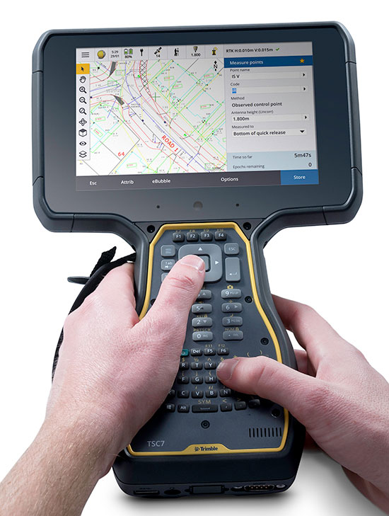
Trimble has released the Trimble TSC7 controller, a new field solution for land and civil construction surveyors. The TSC7 brings powerful enhancements to the field and was designed based on customer feedback, the company said. It provides a tablet experience with a physical keyboard and a sunlight readable 7-inch touchscreen that supports pinch, tap and slide gestures.
Users can interact with the TSC7 intuitively, easily zooming, panning and selecting items on the large touchscreen. Front- and rear-facing cameras allow users to video conference their office from the field for on-the-job support, and capture high-definition videos and images that provide valuable context to their data and clients.
Trimble TSC7 controller.
The TSC7 also leverages the power of Windows 10 Professional, driven by an Intel Pentium 64-bit quad-core processor. The processor and operating system make it easy to process data in spreadsheets and run office software programs. An ergonomic form factor, IP68-certified rugged design and optional, user-interchangeable modules make the TSC7 a flexible solution for all surveying applications.
Trimble also announced a new version of its field software, Trimble Access 2018. The software features a new user interface and powerful graphics capabilities to deliver enhanced workflows for field surveyors.
Access 2018 has been redesigned with even more intuitive menus and screen navigation to take advantage of the TSC7’s 7-inch touchscreen and computing power, while leveraging software workflows, which include applications for general survey, roading, tunnels and pipelines.
Access 2018 also integrates with the Trimble Sync Manager application to enable cloud-based data management between the office and the field. Surveyors can quickly start working by downloading preconfigured jobs in the field with DXF maps and CSV files linked ready to start surveying. Sync Manager also integrates seamlessly with Trimble Business Center software and is compatible with other industry office software platforms.
https://youtu.be/I2oMLIvu3Ck
“Today’s surveyors are managers of geospatial intelligence,” said Ron Bisio, vice president of Trimble Geospatial. “Data has more depth and complexity than ever before, and surveyors’ reputations depend on transforming that data into valuable, reliable information for their clients. The TSC7 and Access 2018 form the new backbone of our field solutions ecosystem, and give our users a leading edge to be data experts.”
Rover Systems
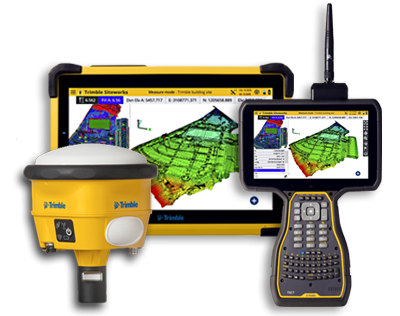
Trimble is also releasing two new rover systems for civil engineering and construction applications — the Trimble Siteworks Positioning System for Construction Surveyors and the Trimble Siteworks Positioning System for Supervisors.
Both systems feature new Siteworks Software, next-generation survey software tailored for construction workflows. Completely redesigned from the ground up, Siteworks Software features a new interface that is optimized for ease-of-use and productivity. Configurable views, colorful graphics and natural interactions and gestures make Siteworks software intuitive and easy to learn.
Siteworks Positioning System for Construction Surveyors is comprised of the Trimble SPS986 GNSS smart antenna, the TSC7 controller and Siteworks software. It enables construction surveyors to work with complex 3D models, collect large data sets faster, visualize complex 3D models more easily and work day or night efficiently.
Siteworks Positioning System for Supervisors is comprised of the SPS986 GNSS smart antenna, the Trimble T10 Tablet and Siteworks software. It enables construction supervisors to run full office software packages, including Business Center – HCE and Microsoft Office, and to work easily with data and 3D models in the field without carrying a laptop.
The Trimble TSC7 Controller running the current version of Trimble Access field software will be available worldwide in May through Trimble’s Geospatial distribution partners.
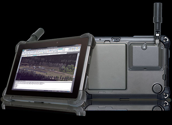
DT Research has released the DT301T rugged RTK tablet (DT301T-RTK), a lightweight military-grade tablet purpose-built for GIS mapping applications. It features real-time kinematic (RTK) satellite navigation to enhance the precision of GNSS position data.
The tablet enables 3D point cloud creation with centimeter-level accuracy, meeting the high standards required for scientific-grade evidence in court.
The DT301T-RTK is a rugged tablet with scientific-grade GNSS. (Photo: DT Research)
The DT301T Rugged RTK tablet is military-grade with an IP65 rating. Because it’s lightweight, the DT301T can be used in the field, office and vehicles, the company said.
A dual-frequency GNSS module is built into the tablet, which uses real-time reference points within 1–2-centimeter accuracy to position 3D point clouds created from aerial photogrammetry, using GPS, GLONASS and Galileo receivers. Users can measure with the RTK GNSS positioning directly using a foldable antenna or connect to an external antenna for more robust receiving and survey-grade precision.
“We’ve seen a dramatic uptick in the need for rugged tablets to be purpose-built for a range of mapping uses across industries,” said Daw Tsai Sc.D., president of DT Research. “In designing the DT301T with RTK satellite navigation, we also took into consideration the other features and capabilities necessary within a rugged tablet to quickly and easily conduct forensic mapping, land surveying, e-construction, building information modeling (BIM) and other mapping scenarios.”
The DT301T is compatible with existing GIS software for mapping applications and brings together the advanced workflow for GIS data capture, accurate positioning and data transmitting.
Uses
According to DT Research, the tablet can be used in a variety of scenarios.
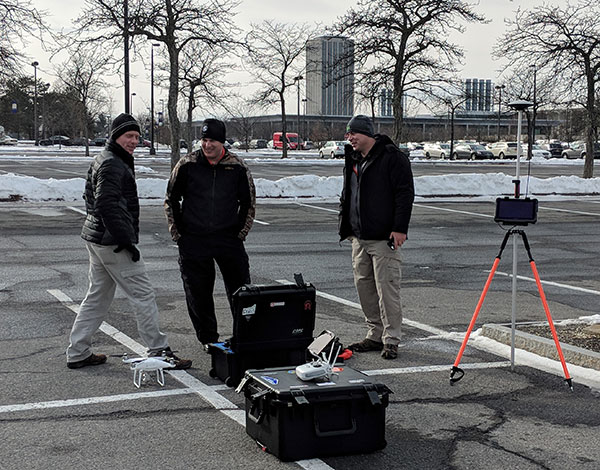
Forensic mapping. Public safety teams, investigators and crash reconstructionists can use the DT301T Rugged RTK tablet to accurately collect measurements that are scientifically defensible by using the real-time centimeter reference points to position 3D point clouds created from aerial photogrammetry or take stand-alone measurements.
DT301T-RTK tablet during forensic mapping training. (Photo: DT Research)
The results will have the precision necessary to stand up as evidence in court, said Andrew S. Klane, a former Massachusetts State Police Lieutenant who teaches Forensic Mapping and is now the chief operating officer at Forensic Mapping Solutions Inc.
“As more drones are being used for mapping, there is a growing need for ground-control positioning devices,” Klane said. “By using a DT301T Rugged RTK Tablet in combination with a drone, users can more quickly and cost-effectively create a 3D model to deliver an accurate representation of the scene with scientific-grade tolerance that will hold up in a court of law.”
It could also help clear crash scenes faster, restoring the normal flow of traffic on congested roadways, reducing secondary crashes and lowering the chance of first responders and other workers getting hurt while clearing the scene.
Land surveying. Surveyors can use the DT301T tablet to measure the altitudes, angles and distances on the land surface so that they can be accurately plotted on a map to determine property boundaries, construction layout and mapmaking.
E-construction. Construction workers can manage the collection, review, approval and distribution of highway construction contract documents in a paperless environment using the DT301 tablet.
Building information modeling (BIM). Architecture, engineering, and construction (AEC) professionals can use the tablet to create 3D models to efficiently plan, design, construct and manage buildings and infrastructure.
FEATURES
The DT301T Rugged RTK tablet has been purpose-built for precision mapping in a variety of environments and includes the following features and capabilities:
Dual-frequency GNSS module: GNSS L1 and L2 RTK that receives GPS, GLONASS and Galileo signals up to 372 channels with RMS 10 mm + 1 ppm accuracy.
High-performance CPU and Windows OS: Intel 6th-generation core i5 or i7 processor with Microsoft Windows 7 Professional or Windows 10 IoT Enterprise. Units come with either 8 GB or 16 GB of RAM.
Sunlight-readable display: A 10.1 inch LED-backlight, sunlight-readable screen with capacitive touch and 1920 x 1200 resolution.
Wireless connectivity: Long-range Class 1 Bluetooth powers connectivity up to 1,000 feet and 4G mobile broadband for LTE, HESPA+, GMS/GPRS/EDGE, EV-DO, Rev A and 1xRTT.
Storage: For field data collecting, the tablet can store up to 1 terabyte of data.
Military standards: The tablet is fully ruggedized to meet the highest durability standards with an IP65 rating, MIL-STD-810G for vibration and shock resistance, and MIL-STD-461F for EMI and EMC tolerance.
Battery pack: High-capacity hot-swappable battery pack delivers 60 or 90 watts for up to 15 hours of continuous mobile communications.
Accessories: Those available include external antennas, pole mount cradles, detachable keyboards, battery charging kits and digital pens.
A roundup of recent products in the GNSS and inertial positioning industry from the April 2018 issue of GPS World magazine.
OEM
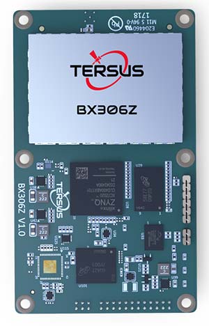
GNSS RTK Board
For OEMs, system integrators
The BX306Z GNSS real-time kinematic (RTK) board has powerful flexibility and compatibility to meet the needs of original equipment manufacturers (OEMs) and system integrators. The BX306Z is a cost-efficient board for positioning and raw measurement output. The board is a compact, multi-GNSS (GPS L1/L2, GLONASS G1/G2, BeiDou B1/B2) RTK module with centimeter-level accurate positioning capability. It is able to integrate with autopilots and inertial navigation units. Log and command is compatible with major GNSS boards.
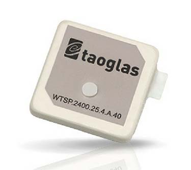
The Taoglas Terrablast antenna line is designed for UAVs and transportation. (Photo: Taoglas)
Rugged antennas
For automotive, drone markets
Terrablast polymer-based patch antennas are 30 percent lighter than their ceramic counterparts and extremely resistant to fracture upon impact. They are designed for the automotive and unmanned aerial vehicle (UAV) markets, where impacts are possible but antenna performance cannot be compromised. The 35-mm GPS/GLONASS/BeiDou patch antenna has high efficiency of more than 70 percent across all bands, improving time to first fix. All Terrablast antennas undergo rigorous temperature, vibration and impact tests, exceed ISO 16750 standards, and are manufactured in Taoglas’ purpose-built facilities in Taiwan and the United States.
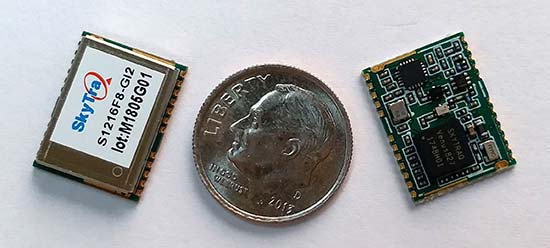
The S1216F8-GI2 is a NavIC + GPS/GAGAN receiver module for emerging intelligent transport systems (ITS) applications requiring NavIC/GPS capability in India. It integrates an L1/L5 RF front-end and baseband processor capable of receiving up to 14 L5 NavIC signals and up to 20 L1 GPS/GAGAN signals simultaneously. With six NavIC signals and three GAGAN signals, it offers 18–23 usable signals, providing improved accuracy in urban canyons. The S1216F8-GI2 is form-factor and pin-out compatible with 12 x 16-millimeter modules, enabling drop-in replacement. NavIC sub-frame data outputs broadcast warning messages for weather alerts and natural disasters. The S1216F8-GI2 is manufactured with ISO/TS 16949 automotive certification.
To meet stringent requirements in harsh environments
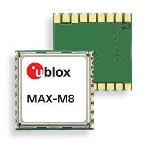
The automotive-grade MAX‑M8Q‑01A GNSS module measures 9.7 x 10.1 x 2.5 millimeters and has an operating temperature range from –40° C to 105° C. It is designed to meet the stringent requirements of the automotive market, providing superior positioning accuracy even in challenging environments such as urban canyons. Its temperature range ensures reliable performance in harsh environments, such as when mounted in a car‑roof antenna.
The Teseo APP receiver enables safer autonomous driving. The multi-frequency GNSS receiver chipset is suitable for safety-critical automotive applications and high-accuracy positioning at the decimeter and centimeter levels for precise point positioning (PPP) and RTK applications. By tracking satellites of all GNSS constellations simultaneously on at least two of the frequencies used by each system, ST’s automotive-quality Teseo APP (automotive precise positioning) receiver provides high-quality raw GNSS data for PPP and RTK algorithms, which allows accurate positioning and rapid convergence time worldwide. The receiver monitors the integrity of the satellite data to alert the system if accuracy is degraded for any reason. This permits Tier-1 manufacturers to certify safety-critical systems in accordance with ISO 26262.
Qinertia post-processing kinematic software has been designed to help surveyors get the most of their surveys. After the mission, Qinertia gives access to offline real-time kinematic (RTK) up-to-date corrections from more than 7,000 base stations in 164 countries. By creating a virtual base station near a project, the software delivers the highest level of accuracy without having to set up a base station. An advanced tight coupling algorithm delivers high accuracy and maximizes RTK availability. Trajectory and orientation are greatly improved by processing inertial data and raw GNSS observables in forward and backward directions, especially in challenging environments. With Qinertia, surveyors can quickly identify and solve issues such as mechanical installations or sensor alignment.
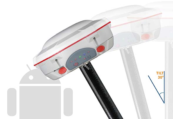
The T300 Plus GNSS receiver is designed for demanding surveying tasks, with full-constellation tracking capability, tilt compensation, 4G/Wi-Fi connection, 8-GB internal memory and an easy survey workflow with Android-based Survey Master Software. It is designed to make collecting accurate data easy and fast, whether done by a beginner or experienced professional surveyor. As an upgrade of the T300, SinoGNSS T300 Plus combines a GNSS board, Bluetooth and adjustable TX&RX UHF, Wi-Fi and 4G modem into one rugged device. Its built-in 4G modem ensures the T300 Plus works with all kinds of continuously operating reference stations (CORS) worldwide. A built-in tilt sensor supports maximum 30° pole tilt and keeps the compensation accuracy within 3 centimeters; the user can check the electronic bubble on the controller for fast surveys in the field.
Atlas-capable GNSS receiver for precision 3D applications
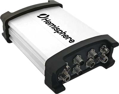
The Vector V1000 GNSS receiver is designed for precision marine applications, such as hydrographic and bathymetric surveys, dredging, oil platform positioning, buoys and other applications that demand the highest level 3D positioning accuracies. It provides high-accuracy heading, position, pitch, roll and heave data. The V1000 supports multi-frequency GPS, GLONASS, BeiDou, Galileo, QZSS and IRNSS (with future firmware upgrade and activation) for simultaneous satellite tracking. The receiver is powered by Hemisphere’s Athena real-time kinematic (RTK) engine and is Atlas L-band capable. Based on Hemisphere’s Eclipse Vector technology, the V1000 uses the most accurate differential corrections including RTK and Atlas L-band. It has an integrated display that can be conveniently installed near the operator. The V1000 has heading accuracy of better than 0.01 degree when using a 10-meter antenna separation.
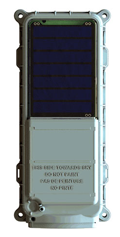
Machine-to-machine (M2M) and internet of things (IoT) device
The SmartOne Solar M2M/IoT device is solar-powered and offers Bluetooth Low Energy connectivity while addressing the growing global demand for reliable and affordable remote monitoring and automated data collection of assets located both within and beyond terrestrial networks. The SmartOne expands the market for remote connectivity to include assets that are otherwise difficult or expensive to reach for power replacement, and lowers the operating cost of monitoring assets being served by legacy SmartOne products. SmartOne Solar’s rechargeable batteries can deliver more than eight years of serviceable life. Without exposure to the sun, a fully charged unit can operate for many months while reporting twice daily. The product’s Bluetooth connectivity allows wireless device configuration and firmware upgrades in the field.
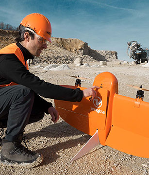
Designed for large-scale surveying and mapping projects
The WingtraOne post-processed kinematic (PPK) drone is the result of collaboration with Pix4D and Septentrio. It is able to deliver orthomosaic maps and 3D models with an absolute accuracy down to 1 centimeter (cm), offering broad coverage and high resolution with ultra-precise accuracy. The WingtraOne can cover 130 hectares (320 acres), equivalent to 240 football fields, in a one-hour flight, and deliver maps at ground sample distances below 1 cm/pixel. Vertical take-off and landing (VTOL) offers hands-free operation and a smoother ride for onboard sensors as well as greater coverage than comparable multi-rotor UAVs. PPK computes ultra-precise geolocations for each image by combining the GNSS data with correction data from a nearby reference receiver. It offers a root-mean-square (RMS) error of 1.3-cm horizontally and 2.3-cm vertically without any ground control points.
DroneHunter is a fully autonomous UAS airspace defense solution. The intelligent robotic aircraft is enabled with TrueView radar designed and engineered for physical remediation of intruder or threatening drones. DroneHunter is an autonomous UAS perimeter detection and protection solution designed to quickly detect, classify and secure against drones and other UAS. When an intruder drone is discovered, DroneHunter can engage autonomously via artificial intelligence (AI)-directed detection, tracking and guidance. Once the rogue drone is identified and the threat level analyzed, DroneHunter safely remediates the threat day or night, at a safe stand-off distance, with no collateral damage. DroneHunter supports multiple drone platforms based on use-case requirements.
By Simon Batzdorfer, Markus Bobbe, Martin Becker and Ulf Bestmann, Technische Universitaet Braunschweig
All images courtesy of the authors.
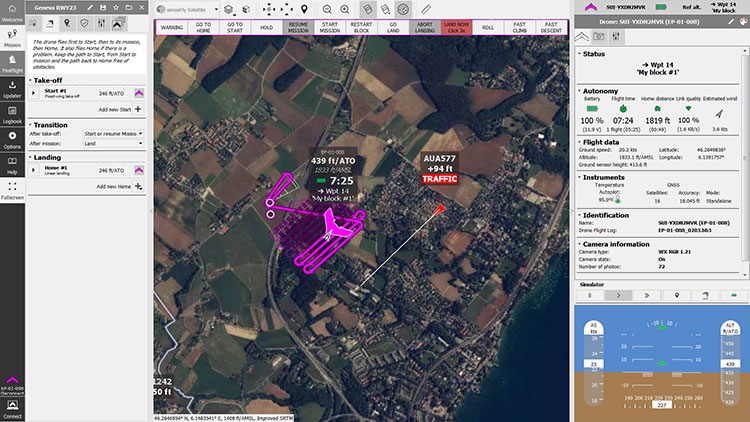
Autonomous vehicles equipped with different environmental sensors, such as optical or thermal camera or a lidar, performed a team survey controlled by a central ground station. The ground station serves as a user interface to define missions and tasks and also to visualize exploration task results online. 2D stitched orthophoto or lidar point clouds are transmitted for display and processing into 3D photogrammetry. Georeferencing data is gathered by an integrated GNSS/IMU positioning system.
In disaster scenarios such as fires, floods or search-and-rescue tasks, good situational awareness is indispensable for responders coping with a complex and often chaotic environment. In most cases, a prior known map data are outdated, and an efficient situational proceeding such as path planning or creation of a search pattern cannot be performed. This information can often only be gathered by manned exploration using ground or airborne systems, with limits on availability.
The research project Automated Navigation and Communication for Exploration (ANKommEn) seeks to create an automated unmanned system to close this gap by providing up-to-date scenario information while increasing the safety of human resources, using unmanned aerial (UAV) and ground-based (UGV) vehicles.
To provide up-to-date information of the desired destination area, all vehicles are equipped with identical positioning and communication hardware complemented by diverse sensors (RGB camera, infrared [IR] camera, lidar) for visual exploration. The visual sensor information is transmitted to a central ground station for visualization and/or analysis. To increase the advantages of the system, the unmanned systems should have a high grade of automation to reduce the workload of the operator so that only basic inputs have to be done by the operator. For example, just by marking a destination area and choosing a predefined task, the mission will be planned automatically, and after the corresponding waypoint-list has been transmitted to the vehicles, the mission will start.
Automated procedures of a UAV in particular require valid position information related to accuracy, availability and continuity. In exploration areas where the UAV operates in low altitude or using a UGV, the reception of the GNSS signal can be degraded by the topology (buildings and such). Using more than one GNSS can increase the availability of position information. Vehicle control, georeferencing environmental sensor data and exploration results all require high-frequency absolute position and attitude and heading information. This data is gathered by fusing GNSS and inertial measurment unit (IMU) data.
OVERALL SYSTEM DESIGN
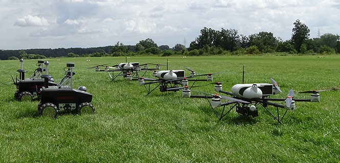
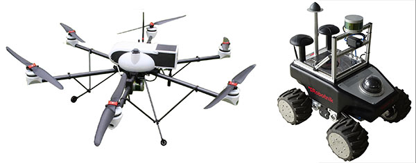
The overall system consists of three UAVs, two UGVs (Opening photo) and a central ground control station. The latter serves as a central human-machine interface to monitor and manage cooperative operation of the UAVs/UGVs by an operator. Based on a priori known map data, exploration areas and tasks are defined and assigned to the UAVs/UGVs and will be updated with actual information of the visual sensors while performing a mission.
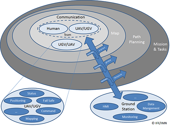
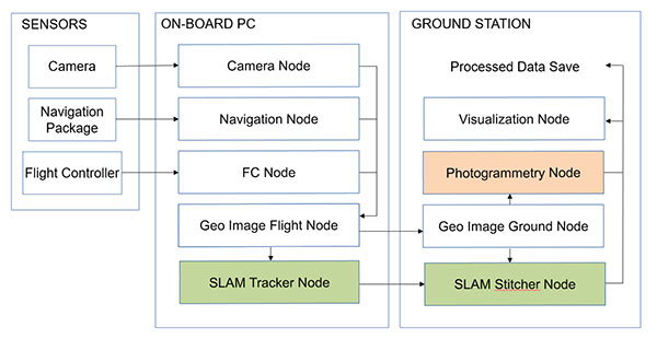
Figure 1 shows the interaction and information exchange between the different vehicles and sensors.
Figure 1. Diagram of interaction and information exchange.
All UAVs/UGVs are equipped with a navigation and communication unit (NAV/COM) and an environmental sensor payload (ENV) unit, including an RGB camera, thermal camera or a lidar respectively.
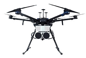
UAV/UGV and Sensor Hardware. The UAVs carry a payload of 2.7 kg (NAV/COM unit, mounted in the upper compartment, and ENV unit mounted under the UAV) and a flight time of up to 30 minutes (Figure 2, left). The payload sensors are carried and stabilized by a two-axis-gimbal. The environmental sensor payload unit is based on three different types of sensors, which are interchangeable between the different UAVs: RGB camera, lidar and IR camera.
For ground-based exploration, two four-wheel-drive UGVs carry a pan-tilt-zoom (PTZ) camera at the top of front chassis (Figure 2, right), and are equipped with a lidar and a thermal camera, or a stereo RGB camera, respectively.
Figure 2. UAV carrying a lidar (left) and UGV carrying lidar and IR camera (right).
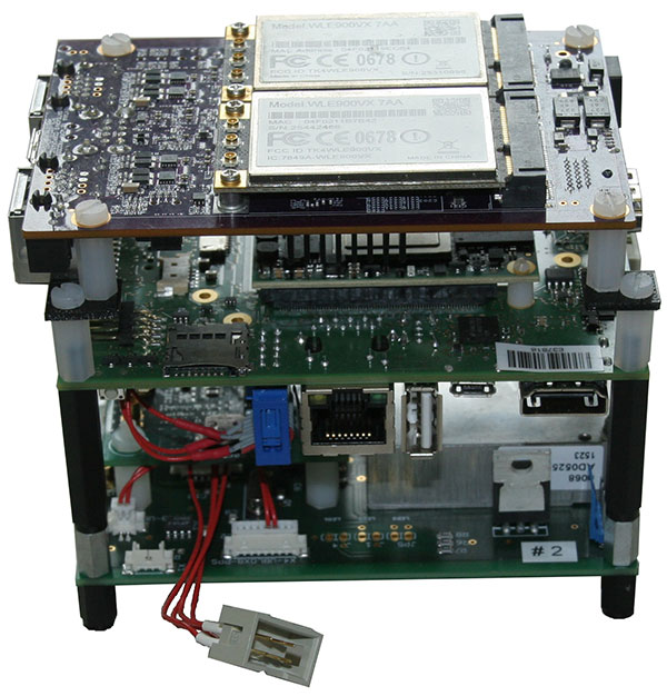
The navigation and communication unit mounted as a stack includes a network processor board for communication and data exchange between the UAV/UGV and the central ground and control station. An embedded processing board provides position calculation and GNSS-NTP-based time server. Data for the position calculation is provided by a custom-designed break-out-board (Figure 3).
Figure 3. Navigation and communication unit.
Data traced by these sensors cannot be sent directly to the ground station because of the huge data amount and the limited bandwidth of the communication link. Therefore, data from the sensors are preprocessed or compressed on a small form-factor personal computer and then transmitted to the ground station.
Ground Station. The ground station is the central device for command, control and visualization of the total system. It provides several options to display the data from the sensors and vehicles and a combination of them, and also provides automated path planning and calculation of the 3D reconstruction (photogrammetry) and online 2D stitched orthophoto.
Software Frameworks. The basic software for determining the vehicle’s state in 3D position, velocity, attitude and heading is established within a modular navigation software framework, with the option to process data of different sensors in real time as well as post-processing for data evaluation and development purposes. Several algorithms for sensor data fusion are implemented. The algorithm for IMU/GNSS fusion is based on an extended Kalman filter and also provides an IMU data-based state vector, stabilized by GNSS information, for the visual sensors. This state vector is published by using the robot operating system (ROS), a framework for inter-process communication based on a TCP or UDP publisher/subscriber concept. The visual sensors and embedded PCs subscribe to different ROS messages, for example, the state-vector-message or information of other sensors.
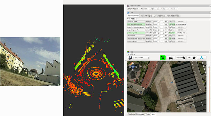
Figure 4 shows examples of the actual camera view from the UGV, and point cloulds and map generated by the UAV. The software layout can be customized by the user.
Figure 4. From left to right: the actual view by the PTZ camera onboard the UGV, the point cloud gathered by the UAV’s lidar, and the mission parameters and map of an aerial view.
POSITIONING OF UAV AND UGV
Automated operation of UGVs and UAVs requires valid position as well as attitude and heading information. In the case of using only one GNSS, signal quality and availability can be degraded by the environment (buildings) and can result in less precise or even a lack of position information.
GNSS Multi-Constellation. To overcome the risk of poor availability of GNSS-based position information, parallel usage of different GNSS can raise the number of received satellite signals: GPS, GLONASS, the evolving Galileo and BeiDou. When using a multi-constellation approach for positioning, one has to take care of several differing aspects between the GNSS. Each system uses a different geodetic reference frame and time basis. Measurements gathered from another GNSS system must be transformed into the reference frame of the desired system. The geometric distribution of the satellites is improved by using more than one GNSS constellation, indicated by a lower dilution-of-precision value.
The navigation software framework is designed for real-time computation and also for post-processing. In post-processing, the recorded sensor data is streamed to the software framework with the option of changing several parameters and settings for calculation. One option is to exclude satellites at low elevation from position calculation by changing the cut-off elevation for these satellites. This parameter will be changed to simulate environmental conditions that block receiving GNSS signals, like buildings within urban scenarios, to compare the availability of received GNSS signals for single- and multi-constellation-based position calculation.
Recorded data of a real-world test serves as the database for the post-processing with different cut-off elevation parameters. At the beginning of the field test, there was a short initialization period to boot the OS and to start basic processes for positioning. After that, a predefined mission was flown and the GNSS measurements have been saved for the described post-processing.
Post-processing has been performed with different cut-off elevation parameters of 5° up to 35°. In the case of 35°, the number of GPS satellites is reduced to the minimum for position calculation of four, in contrast to 5–7 available satellites for a multi-constellation based solution.
GNSS/IMU Fusion. Using the GNSS multi-constellation approach can increase availability of position information. For attitude and heading determination, an IMU is nevertheless indispensable. Additionally, the frequency of the pure GNSS-based positioning information is usually between 1 Hz to 5 Hz within the described hardware setup. Meaningful georeferencing of the environmental sensors requires much higher frequency position and attitude information.
The IMU provides high-frequency 3D measurements of accelerations and angular rates. Using common strapdown algorithm processing, high-frequency position, velocity, attitude and heading information is provided in real time. Due to the short time stability of pure inertial navigation, the GNSS positioning results are used for aiding purposes within the Kalman filter’s update step. To overcome the absence of GNSS aiding information even when using multi-constellations, there are mainly two options. First, a short coasting period is possible after the data fusion has reached a steady state.
Second, due to the highly modularly design of the navigation software framework, it is possible to use position or attitude increments from environmental sensor data processing for aiding the IMU.
The vehicle’s state vector is then distributed with high frequency within the system for georeferencing measurements of the environmental sensors, especially the RGB camera and the lidar for photogrammetry and simultaneous location and mapping (SLAM) applications.
PHOTOGRAMMETRY AND SLAM
In major fire scenarios, maps can be out of date. Therefore, techniques have been developed to gather a 2D overview based on several single RGB pictures taken and processed on board a UAV and transmitted to the ground station via data links. Additional processing of a 3D reconstruction of the scenario is an integrated feature within the ground station. Both approaches were implemented to get an automated rapid aerial mapping solution.
In the case of the 2D overview, SLAM algorithms, often used in robotic research, are adapted for this specific use case. These algorithms provide good results for a rapid aerial mapping solution to get an overview of the scenario, because the map is updated incrementally with every new image, but they are less precise, which can be compensated for by using the photogrammetric 3D reconstruction. The live mapping (SLAM) approach is based on the ORB-SLAM algorithm, and the photogrammetry-based approach uses commercially available photogrammetry software.
The systems, on the UAV for 2D and for 3D on the ground station, use the ROS framework for processing the visual sensor data and the described techniques for positioning, georeferencing and attitude determination. For data exchange between these frameworks, several software interfaces have been implemented. Figure 5 displays a flowchart of the implemented workflow.
The sensor/input data is received by corresponding nodes on the aerial vehicle. After adding the camera pose information to the image in the geo-image flight node, the image is sent to the geo-image ground node on the ground station. The SLAM process is separated into two parts. The SLAM tracker node calculates the transformation between images, and the SLAM stitcher node applies the transformations. The transformed images are displayed by the visualization node. The photogrammetry node receives the georeferenced images, stores the data, and initiates the photogrammetric processing once the survey is finished. The results can also be displayed by the visualization node and exported in a desired format.
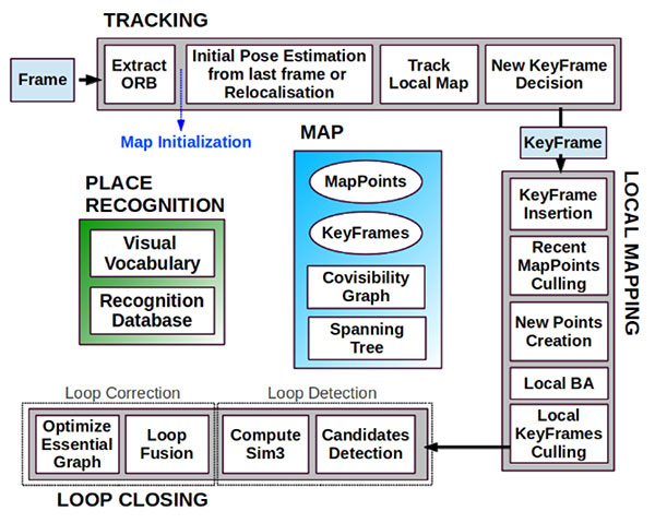
Visual SLAM. Computer vision-based algorithms have developed rapidly over the last few years. One method estimates a pose by using monocular image processing, known as parallel tracking and mapping (PTAM). This integrates a bundle adjustment and separates the tracking and the mapping procedure into different threads, leading to a real-time capable framework. These basic PTAM principles have been integrated into a robust loop-closing and another method of relocalization, known as Oriented FAST and Rotated BRIEF (ORB SLAM), shown in Figure 6. Here, tracking, local mapping and loop closing are separated into different threads (gray boxes), with the main map and place recognition in the middle.
Figure 6. ORB SLAM system overview [Mur-Artal, 2015].The tracking thread predicts the current pose from the last known position and movement by using a constant velocity model and performs a guided search of map points. If these points are found near the estimated position, the velocity model is valid and the tracking procedure continues. Otherwise, the tracking is lost and a relocalization in the global map starts by using a subset of features, which are increased after detection of corresponding features in other keyframes to optimize the camera pose and, finally, the tracking procedure continues. The last step of this procedure is to decide whether the current frame contains enough information to be inserted as a new keyframe for further calculations.
To mark a frame as a new keyframe, the frame must fulfill all of the following conditions:
More than minimum number of frames has passed.
Local mapping is on idle or condition 1 fulfilled.
A minimum number of 50 points is observed.
A maximum of 90% of the features is already observed by the other frames.
When a new keyframe is passed to the local mapping procedure and inserted as a node into a co-visibility graph structure, new correspondences are searched in the connected keyframes to triangulate new points. Based on the information accumulated during the tracking, a point culling keeps only high-quality points in the map as well as a culling of redundant keyframes.
Then a loop closing is performed. This is one of the main improvements compared to PTAM. If a loop is detected, the drift accumulated in the loop is computed, and both sides of the loop are aligned and visible points are fused. In a final step, a pose graph optimization is done to achieve global consistency.
This information of the 3D camera pose is used to generate a 2D orthophoto in real time while the vehicle is flying. To create a 2D orthophoto, a common reference frame is approximated, which is orthogonal to all camera measurements. The projection is performed by using a projection model based on a pinhole camera.
After the compensation and distortion, the whole image can be stitched to the current global map.
Photogrammetry. This approach uses off-the-shelf photogrammetric processing software. The processing is triggered automatically when the survey is completed and all images are transferred to the ground station via data link. For georeferencing of the images, the camera location and the inner camera geometry were written to the EXIF file of each image by the geo-image ground node (Figure 5). To ensure an acceptable compromise between orthophoto quality and the required processing time, an analysis regarding the impact of the most relevant processing parameters has been performed.
Figure 5. ROS node layout with SLAM (green) and photogrammetry workflow (red).
The photogrammetry process consists of four steps:
camera alignment (optimizing the homographic equation)
mesh creation by generated tie points
orthophoto creation (dense cloud or digital elevation model)
export.
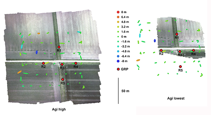
Analyses and Evaluation. To evaluate the correct workflow of both approaches of 2D live-stitching and the 3D photogrammetry, a real-world flight test above agricultural cropland has been performed. The results of both approaches are shown in Figure 7 and Figure 8. Generally, agricultural cropland and its mean textured surface pose a challenge for mapping processes because of the limited number of trackable features.
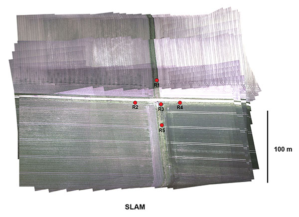
Figure 7. Orthophotos created with the profiles high and lowest (including ground reference points).Figure 8. Orthophotos created with 2D live stitching approach of cropland.
Four predefined profiles were used to cover the requirement of compromise between processing duration and quality of the generated orthophoto. Each profile level generates a corresponding level of alignment accuracy and mesh face count: lowest, low, medium and high.
To estimate the accuracy of the created maps by the different profiles, five ground reference points (GRPs) were distributed over the mission area. The location of the GRPs was determined using a RTK-GNSS system leading to a horizontal RMSE below 2 cm. To enable robust processing for this scenario, the overlap and the sidelap was chosen to be 70%. A ground-sampling distance (GSD) of 2 cm was needed to identify the GRPs. This resulted in a mission consisting of six times 100-meter (m) lines with a distance of 25 m in an altitude of 60 m over ground. During the flight time of 4.5 minutes, 271 images were taken.
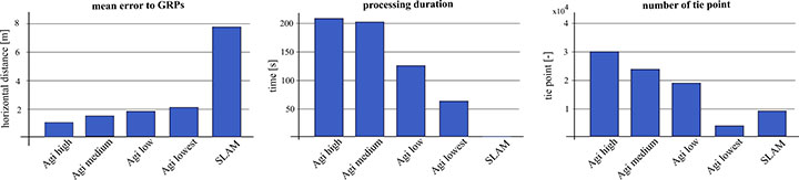
To compare the profiles, they were triggered one after another with the same set of images. The created results are shown in Figure 7. All profiles resulted in consistent solutions and were successfully georeferenced. The map based on the lowest profile could not recreate the complete area (Figure 7, right). The remaining profiles led to similar results without notable differences to visual inspection. The processing time varied between 1.2 and 3.6 minutes. A comparison of this and other criteria is given in Figure 9.
Figure 9. Evaluation and comparison of defined software profiles and visual SLAM.
The created final image of the SLAM pipeline is shown in Figure 8. The image was updated with every new image and was therefore finished before the UAV landed. The mean location error measured using the reference points was about 8 m, significantly larger than the errors observed in the photogrammetry results. In Figure 9 the results are contrasted to the results of the photogrammetry approach.
While the mean error in the low profile is half as high as in the lowest profile, the calculated errors using the medium and high profiles are not enhanced significantly. The number of tie points created by the lowest profile is an order a magnitude lower compared to the other three profiles.
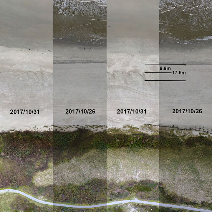
We conducted flight tests on Langeoog island in the North Sea, to gather information on efforts to protect the island’s coastline from water erosion. For this reason, sand was selectively washed up to the coastline by dredgers at the beginning of October 2017. Between Oct. 26 and 31, due to severe weather with a storm flood, a huge erosion of the washed up sand occurred, and the result is shown in Figure 10. The level of erosion was determined by comparison of the orthophoto of the same area. The dislocation averaged out to 9.9 m with some peaks up to 17.6 m.
Figure 10. Evaluation of erosion.
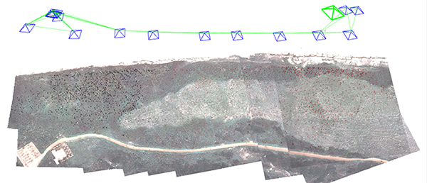
The 3D photogrammetry provides a more detailed image compared to the image of the 2D-live-stitching approach (Figure 11), but both approaches can provide the desired information of the area.
Figure 11. Result of the SLAM approach with camera poses and tracked features.
Both implemented approaches were successfully integrated to get the desired fully automated rapid aerial mapping solution. This also includes the basic tasks of the automated mission planning, camera control, image transport to ground station, automated processing and the visualization of the results.
CONCLUSION
The benefits of multi-constellation GNSS positioning have been demonstrated with a focus on UAVs and UGVs operating in catastrophic scenarios, especially where GNSS signal reception might be blocked. This position information is also used for georeferencing of images and visual reconstruction of the area. The overall system has demonstrated the capability of an automated orthophoto generation. Both implemented mapping methods — a 2D live stitching and a 3D photogrammetry — provided results that fulfill the requirements to get an instantaneous 2D overview and a contemporary 3D reconstruction of the area.
ACKNOWLEDGMENTS
This work was done within the joint research project ANKommEn, funded by the German Federal Ministry of Economic Affairs and Energy, administered by the Space Administration of the DLR (funding code: 50NA1518). Project partners are the Institute of Flight Guidance (IFF), the Institute of Mobile Machines and Commercial Vehicles (IMN) — both part of Technische Universität Braunschweig — and AirRobot GmbH & Co. KG, a German manufacturer of multirotor UAVs. The professional fire brigade of Braunschweig and the Lower Saxony Water Management, Coastal Defense and Nature Conservation Agency also participate as associated project partners.
SIMON BATZDORFER holds a Dipl.-Ing. in mechanical engineering and is a research engineer at the Technische Universitaet Braunschweig, Institute of Flight Guidance (IFF).
MARKUS BOBBE holds a M.Sc. in aerospace engineering and is a research engineer at the Braunschweig IFF.
MARTIN BECKER holds a Dipl.-Ing. in aerospace engineering and is a research engineer at the Braunschweig IFF.
ULF BESTMANN received his Dr.-Ing. in mechanical engineering from TU Braunschweig. He is head of the navigation department of the IFF. He co-founded the company messWERK GmbH, a service provider in flight testing and certification.
My last column described how the U.S. National Geodetic Survey (NGS) used the detailed analysis of the latest GPS on Bench Marks dataset to:
generate a prototype hybrid geoid model to evaluate the residuals at stations not used in the hybrid geoid model,
confirm that the stations recommended for re-observations should be observed again, and
identify void areas that need additional observations.
Since GEOID12B was created, users have been instrumental in providing OPUS with results on benchmarks in areas where NGS said that additional stations were needed. It showed how NGS used the detailed analysis to prepare material to assist users on strategically occupying stations to help support the GPS on Bench Marks Program and create a hybrid geoid model that accurately represents a current NAVD 88.
To eliminate confusion of where NGS would like new observations, NGS’ material contains a specific list of stations that it would like occupied with GNSS during the 2018 GPS on BMs program. My previous column provided a summary of the latest details of NGS’ 2018 GPS on BMs campaign, which will be used to create the next hybrid geoid model in 2019.
The analysis described in my column was the first cut at identifying stations that should not be used in a hybrid geoid model, and providing a list of specific stations that could help improve the hybrid geoid model. All new data received by the cut-off date of Aug.31, 2018, will be analyzed by NGS and, if appropriate, the results will be included in the next hybrid geoid model.
This is a great opportunity to provide data that will help to improve the hybrid geoid model in your region.
This column will describe NGS’ GPS on BMs 2018 interactive web map and provide an update and status report on stations observed in support of the 2018 GPS on BMs Program.
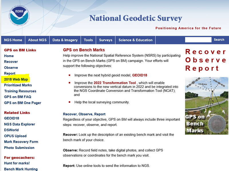
First, NGS has a web page dedicated to the 2018 GPS on BMs program. See the box titled “GPS on Bench Marks Web Page.”
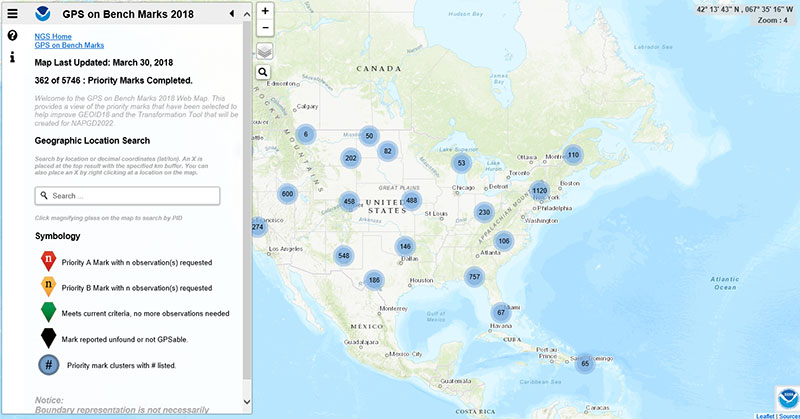
The GPS on BMs 2018 web page contains a link to a web map where users can determine which bench marks NGS would like users to occupy before the Aug.31 deadline. On the left-hand side of the web page there is a link titled “2018 Web Map” (see highlighted section of box titled “GPS on Bench Marks Web Page”). The next few boxes demonstrate how a user can use the web map tool to locate bench marks in their local area of interest. The box titled “2018 Web Map” depicts what the user will see when the link “2018 Web Map” is clicked.
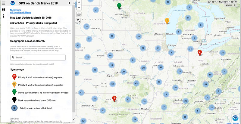
The user can then click on the map and the tool will provide more details. The box titled “Map After Clicking on Priority Mark Cluster #488 in the Great Plains Region“ is a depiction of the map after clicking on a priority mark cluster.
Map After Clicking on Priority Mark Cluster #488 in the Great Plains Region
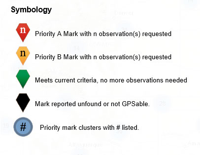
The user can continue to check on the map until the map depicts individual bench marks where the symbology indicates the status of the monuments. The symbology labels are fairly straightforward. The box titled “The Web Map Symbology” provides the five different categories of monuments.
The Web Map Symbology
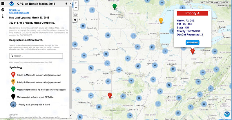
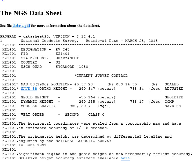
NGS is updating the map weekly to reduce users occupying stations that already have enough redundant observations. Clicking on a station provides the status of the station. The box titled “An Example of a Priority A Station” depicts station (PID KZ1401) that is labeled as a Priority A station and requires two observations.
An Example of a Priority A Station
The user can obtain the datasheet for the station by clicking on the Datasheet button in the box (see box titled “Excerpt from the Datasheet for PID KZ1401”).
Excerpt from the Datasheet for PID KZ1401
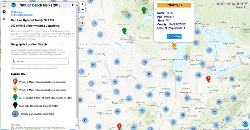
The box titled “An Example of a Priority B Station” depicts a priority B station (PID PM0117) that NGS would like one more observation. Users should remember that priority A stations are more important than priority B stations but B stations are still important for the development and analysis of the hybrid geoid model.
An Example of a Priority B Station
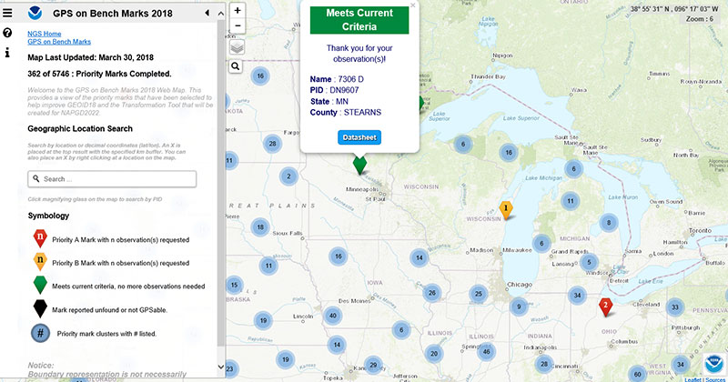
The box titled “An Example of a Station that Meets Current Criteria” provides an example of a station that does not need any more observations. As previously stated, NGS will be updating this web map on a regular basis so users will not waste their time and resources.
An Example of a Station that Meets Current Criteria
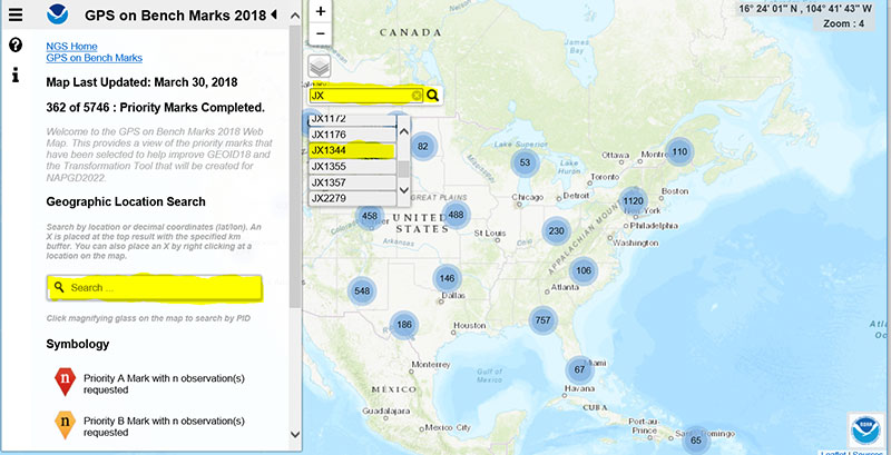
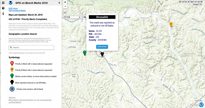
The web map has a search feature, so if the user knew a priority A or B station’s PID, they could locate the station on the map. The box titled “An Example of Using the Web Map Search Feature“ demonstrates the search feature using PID JX1344 (see highlighted section in the box).
An Example of Using the Web Map Search Feature
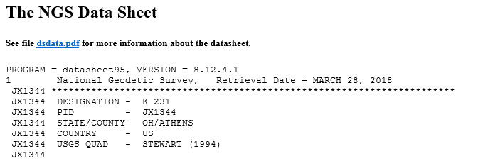
The box titled “Output from Search Feature for PID JX1344“ is a depiction of the output using the search feature.
Output from Search Feature for PID JX1344
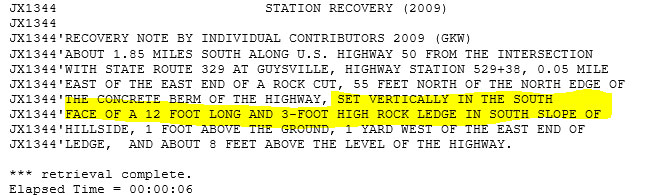
The last category of stations that are shown on the web map are monuments that are reported as unfounded or not GPSable. This is very useful information for NGS and others to have on datasheets. The box titled ” Output from Search Feature for PID JX1344 “ depicts bench mark PID JX1344 that is labeled as unfound or not GPSable. The datasheet for JX1344 indicates that the bench mark is set vertically in a rock ledge (see highlighted section in the box titled “Excerpt from the Datasheet for PID JX1344.”
Excerpt from the Datasheet for PID JX1344
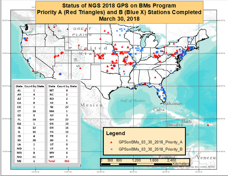
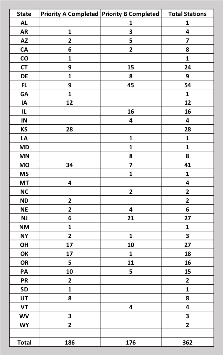
As of March 30, 362 of the 5745 priority marks have been completed. The box titled “Status of NGS 2018 GPS on BMs Program as of March 30, 2018“ is a plot of the stations that are completed, and the box titled “Count of Stations Completed by State “ provides the number of stations completed by state. The red triangles are priority A stations completed and the blue “X” are priority B stations labeled as completed.
It appears that the central portion of the country has been very active. For example, there are 34 priority A stations completed in Missouri and 28 completed in Kansas. The State of Florida has completed 45 priority B and nine priority A stations for a total of 54 stations (see box titled “Count of Stations Completed by State “).
Status of NGS 2018 GPS on BMs Program as of March 30, 2018
Count of Stations Completed by State
March 30, 2018
The number of stations completed to date represents about 6 percent of the total number of stations that need to be observed. Aug. 31 is only five months away. Hopefully, the number of completed stations will significantly increase during the next several months.
If you have a GNSS receiver, please identify a priority monument nearby and occupy it. As I have explained in previous columns, there are many invalid GPS on BMs stations that may be used in the next hybrid geoid model unless more benchmarks with valid NAVD 88 heights are observed with GNSS.
Please encourage your fellow surveyors and friends to occupy a benchmark to support the next NGS hybrid geoid model. This is your opportunity to help develop a current, valid hybrid geoid model in your area.
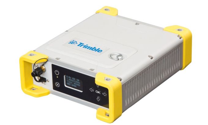
The MPS865 GNSS receiver is designed for marine positioning.
Trimble has debuted the MPS865 marine positioning system multi-frequency and multi-application GNSS receiver.
The Trimble MPS865 is a versatile, rugged and reliable GNSS positioning and heading solution for a wide variety of real-time and post-processing applications for marine survey and construction.
It features integrated communications options such as Wi-Fi, UHF radio, cellular modem for internet connectivity, Bluetooth and MSS satellite-based correction channels.
The patented GNSS-centric technology uses all available GNSS signals to deliver reliable positions in real time. The GNSS receiver provides for the connection of two GNSS antennas for precise heading.
With a modular form factor, the MPS865 is flexible and can be used as an integrated on-board rover receiver, a base station or a continuously operating reference station. According to Trimble, the built-in precise heading feature ensures the receiver is of minimal size, consumes less power and has less cabling, which are all benefits when on-board space it at a premium.
The MPS865 adds new features to improve usability in a congested marine construction site – multi constellations, cellular connectivity and beacon support. The multi-constellation option maintains productivity in marine sites or when antennas or satellites are partly obstructed.
At many sites, the receiver can use the free-to-air beacon support. When coupled with GA830 antennas, the MPS865 will receive the free-to-air beacon signals to deliver sub-meter accurate horizontal positioning in many parts of the world. It always delivers precise heading even when no GNSS corrections are received.
The marine receiver also has cellular, making it easier to use Internet Base Station Service (IBSS) and VRS corrections over the internet as well as communicate with the receiver via the internet and SMS messages. The receiver also can be used as a data access point on the vessel to download design files or for immediate remote support.
The MPS865’s design enables a broad range of mounting capabilities and built-in communication options. Features include an internal removable battery, internal memory and optional accessory kits for specific applications.
The receiver is also compatible with a variety of software solutions including the new Trimble Marine Construction software.
The weatherproof, high-impact-resistant moulded aluminium housing protects it in extreme marine conditions or base-station applications.
“With the addition of the MPS865 receiver to our portfolio, Trimble has introduced a new generation of rugged, compact and feature-rich GNSS, a solution the marine industry has been needing for some time,” said Scott Crozier, general manager of Trimble’s Civil Engineering & Construction Division. “This highly flexible and capable receiver can be combined with our marine construction software providing contractors with a market-leading solution for any marine survey or construction application.”
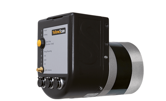
YellowScan has launched a new lidar system, the Surveyor Ultra. It integrates the Velodyne VLP-32C scanner and the Applanix APX-15 GNSS/inertial measurement unit (IMU).
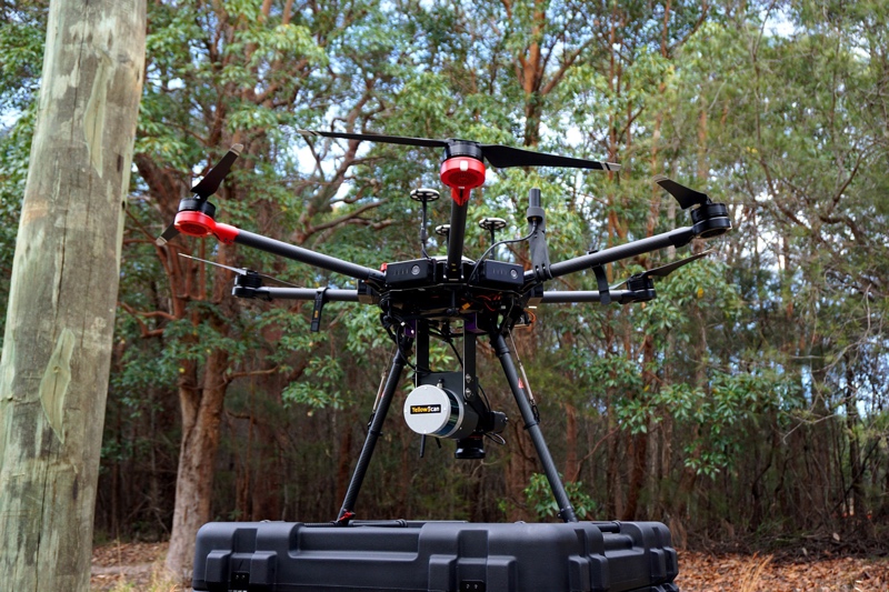
With high density (600,000 shots per second), the system is suitable for high-speed UAVs and long-range needs (maximum range: 100 meters). Its light weight (1.7 kg) makes it easy to mount on any drone, including vertical takeoff and landing (VTOL) UAVs.
As for all YellowScan lidar systems, the Surveyor Ultra is a turn-key system fitted for under vegetation 3D modeling and fast data processing, the company said.
Applications such as forestry, archeology and environmental research will benefit from Surveyor Ultra, as they require long-endurance flights high above trees or over rocky mountains and rugged terrain.
“The Surveyor Ultra shows great potential to safely and efficiently operate lidar on lightweight fixed-wing UAVs,” said Tristan Allouis, YellowScan CTO. “The Surveyor Ultra completes our product line, including the successful Surveyor Lidar System (integration of the VLP-16 scanner from Velodyne).”
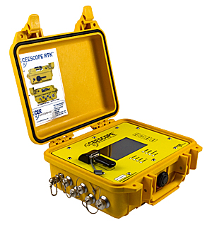
The NovAtel OEM6 GNSS receiver card used in the CEESCOPE echo sounder has been replaced with NovAtel’s latest low-power, high-performance OEM729 receiver.
With 555 channels, the new GNSS option brings a vast increase in available channels for future-proofing, improved interference rejection and better performance in challenging environments, the company said.
The TerraStar L-Band support remains.
The OEM729-equipped CEESCOPE is available with a built-in UHF radio modem and direct Ethernet connectivity to the GNSS receiver for NTRIP cell-phone real-time kinematic corrections.
SenseFly is partnering with Trimble to optimize the drone mapping workflow for geospatial professionals.
The new integration is designed to ensure a smooth end-to-end mapping drone workflow. senseFly operators can now, within the recently launched eMotion 3.5 software, transform a senseFly S.O.D.A. camera’s georeferenced imagery into an automatically collated project (in .jxl format).
This enables the one-click import of drone imagery into the Trimble Business Center Aerial Photogrammetry module without the need for manual project creation and organization of images.
The senseFly-to-Trimble mapping workflow includes:
planning and monitoring a senseFly S.O.D.A.-based drone flight (in eMotion 3.5)
downloading the drone’s images for one-click georeferencing in eMotion 3.5 (Flight Data Manager)
clicking to create a .jxl format mapping project
opening a project within the Trimble Business Center Aerial Photogrammetry module
processing the drone’s imagery to generate orthophotos, contour maps, point clouds, digital surface models (DSMs) and feature maps
analyzing and acting upon the data.
Screenshot: Trimble
“Making work easier and more efficient for geospatial professionals is the goal that drives every solution we develop,” said Jean-Christophe Zufferey, senseFly co-founder and CEO. “Therefore, we are excited to collaborate with Trimble on more tightly integrating our solutions, since enhancements such as this new eMotion-to-Trimble Business Center workflow do exactly that, ensuring that the transition from data collection to acting upon this data is as seamless as possible.”
The senseFly S.O.D.A. is built for professional drone photogrammetry work. The 1-inch, 20-megapixel RGB camera captures sharp aerial images across a range of light conditions, allowing senseFly fixed-wing drone operators to produce detailed, vivid orthomosaics and ultra-accurate 3D digital surface models.
senseFly S.O.D.A. is compatible with most senseFly fixed-wing mapping drones, including the large-coverage eBee Plus.
Trimble Business Center allows surveyors and other geospatial professionals to combine aerial photography with data collected from GNSS receivers, total stations, 3D laser scanners and more, for a complete field-to-finish workflow. By combining imagery from unmanned aerial systems with ground-based survey data, users can visualize their project from both aerial and terrestrial perspectives, measure points within the images and create 3D models of the infrastructure and terrain.
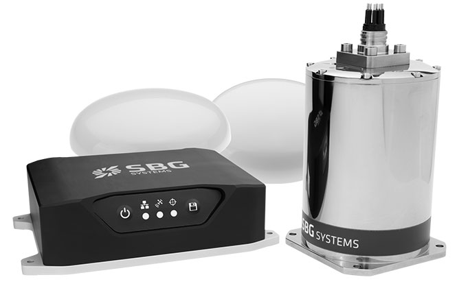
SBG Systems has released the Navsight marine solution, a full high-performance inertial navigation solution designed to make surveyors’ tasks easier in both shallow and deep water.
Navsight consists of an inertial measurement unit available at two different performance levels (from shallow to deep water). According to SBG Systems, the Navsight marine solution is based on 10 years of the company’s experience in marine inertial sensing products.
Whether the IMU comes with a surface or a subsea enclosure, they are all lightweight and easy to install, the company said. Navsight connects to any computer, with no software installation. Once connected through Ethernet, the web interface guides the user to configure the solution.
A 3D view of the boat shows the entered parameters so that the user can check in real time the installation. Navsight allows quick installation and initialization thanks to new mechanical calibration module. The embedded filtering controls and validates lever arms and antenna alignment during this procedure.
Navsight Marine Solution provides high-performance motion and navigation data as well as a real-time heave accurate to 5 cm, which automatically adjusts to the wave frequency, SBG Systems said.
To allow surveying when wave frequencies are large or complex, Navsight comes with a delayed heave feature resulting in a heave accurate to up to 2-cm computed in real-time with a little delay.
If higher performance is required, the surveyor can count on SBG INS/GNSS post-processing software named Qinertia. By processing inertial and GNSS raw data forward and backward, Qinertia greatly increases accuracy especially during GNSS outages; it also fixes set up mistakes.
Highly versatile, Navsight comes as a Motion Reference Unit, providing roll, pitch and heave or as a full navigation solution with embedded tri-frequency GNSS receiver, or using an external one. Fusing inertial data with satellite position in real-time, Navsight INS offers continuous position in all conditions, such as surveying under a bridge, or during a GNSS outages due to coastal infrastructures (buildings, harbor cranes, etc.).
The Navsight Marine Solution supports RTK and every precise point positioning service (Marinestar, TerraStar, etc.). It is compatible with the main hydrographic software such as Hypack, QINSy or Teledyne PDS for seamless integration into existing workflows.
Navsight is ITAR-free. All models are available for order. Ordering information and delivery time are available from SBG Systems representatives and authorized SBG Systems dealers.