Category: Survey

  • Launchpad: Antennas, autonomous vehicle platform

    SURVEY & MAPPING

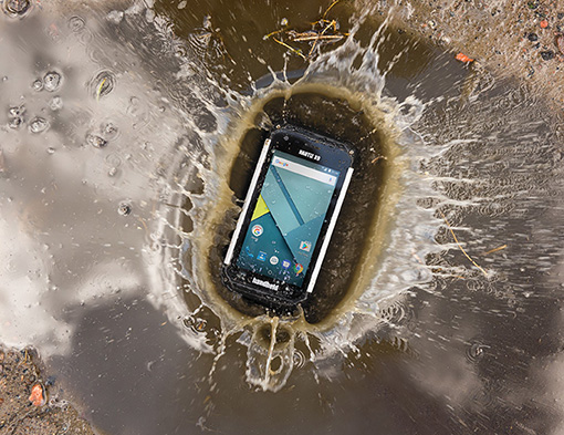
    Mobile surveying app

    Increases RTCM 3.1 support

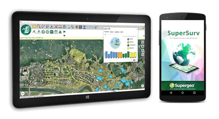
    SuperSurv’s NTRIP solution is being enhanced to adopt more RTCM versions and provide a better GNSS positioning service. NTRIP (Networked Transport of RTCM via internet protocol) is a protocol to send GNSS-related data through the internet, which enables users of differential GPS or network real-time kinematic (RTK) to get correction parameters after connecting to the internet. The correction parameters can be used to calculate a more accurate GNSS location. Supergeo’s product team is developing the support for RTCM 3.1, including Types 1021 and 1023.

    Supergeo Technologies, www.supergeotek.com

    Smart antenna

    For harsh outdoor applications

    The scalable A222 GNSS smart antenna is designed for both agriculture and basic indicate systems markets, as well as other markets requiring flexible positioning. The smart antenna has the flexibility to scale and grow as business expands and can be configured from L1-only to multi-GNSS, multi-frequency and real-time kinematic (RTK). It adds a system component so that tractor and farm equipment manufacturers can deliver their own guidance and control solutions to their customers. Designed to excel in challenging environments, the A222 uses Hemisphere’s Athena RTK engine and is Atlas L-band capable. It is easy to mount and customizable. Its dual-serial, CAN and pulse output options are compatible with almost any industry-standard interface. Because the A222 is Atlas-capable, it has the ability to use the new Atlas AutoSeed technology. Atlas AutoSeed allows users to suspend Atlas use for any period, and upon returning to their last location, AutoSeed rapidly re-converges to a high-accuracy converged position. A222 comes pre-configured with Atlas Basic activated.

    Hemisphere GNSS, hemispheregnss.com


    OEM

    Location architecture

    Locates mobile devices moving indoors and outdoors

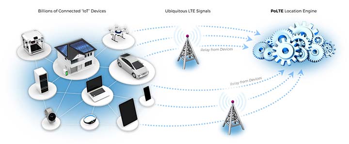
    Leveraging ubiquitous LTE signals, the Lite-Touch Architecture calculates positioning in the cloud to efficiently locate devices between indoor and outdoor environments. By offloading computation-heavy location calculations from the device to the cloud, the PoLTE positioning solution makes location positioning available to a wider variety of devices, including those constrained by battery life, memory, processing power, size and cost. This includes IoT-based applications that historically relied on GPS, with its high rate of power consumption, as well as Wi-Fi and Bluetooth with their added size, cost and network complexity.

    PoLTE, www.PoLTE.com

    Time server

    Enhanced for Ethernet networks, satellite uplinks

    Enhancements to the SyncServer S600 series of time servers and instruments improve time synchronization over enterprise Ethernet networks and supply timing signals for improved military radar operations and satellite uplink communications. The SyncServer S600 series also meets the timing and synchronization needs of the rapidly evolving networks of enterprise and financial customers, particularly for compliance purposes such as the European MiFID II directive, which specifies highly stringent time accuracy requirements for stock trading systems. The latest release includes support for the IEEE 1588 multiport, multi-profile Precision Time Protocol (PTP), which allows the S600 to operate as an independent grandmaster clock on each Ethernet port — delivering cost savings and network deployment flexibility to customers. This is coupled with a new 10-GbE interface to easily interoperate with a wider variety of network and stock trading topologies.

    Microsemi Corporation, microsemi.com

    Defense-developed IMU

    Available to customers worldwide

    The HG4930 inertial measurement unit (IMU) is tailored for “straight-out-of-the-factory” integration and use in various non-defense and non-aerospace industrial applications including surveying and mapping, autonomous vehicles and gimbal stabilization. The HG4930 IMU is not classified under an International Traffic in Arms Regulation category; it is free from the burden of an export license for all but a few military-related use cases. The micro-electro-mechanical system (MEMS)-based IMU has been tailored to provide significantly improved gyroscope and accelerometer performance for the environments and use cases experienced by non-aerospace and non-defense users.

    Honeywell, honeywell.com

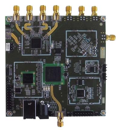
    Frequency-hopping modem

    With anti-jamming

    The HX-DU2017D is a frequency-hopping OEM modem designed to provide strong anti-jamming and signal receiving capability for complex data-intensive applications. HX-DU2017D is a miniature, dual-frequency, software-selectable 840-MHz and 900-MHz data link modem. It provides power switching of 0.5 W, 1 W and 2 W; 20 ms/30 ms/40 ms/50 ms/ frequency-hopping intervals; and supports point-to-point, point-to-multipoint network. Its full duplex mode ensures secure data transferring and stable long-range communication. The HX-DU2017D also provides short latency of data transmission and communication recovery in millisecond level. It allows fast and secure simultaneous data communication for mission-critical applications, especially in the fields of precision agriculture and UAVs, including unmanned plant surveys, UAV plant protection and automatic mowers. It could be placed on a UAV with its extremely small footprint for tight OEM integration and design flexibility. Meanwhile, its frequency-hopping transmission ensures UAV data security and flight stability.

    Harxon, en.harxon.com


    UAV

    Thermal imaging

    For small construction, thermal inspections and public safety

    The Parrot Bebop-Pro Thermal is a compact quadcopter with two embedded cameras: a stabilized 14-megapixel high-definition front-facing video camera and a FLIR ONE Pro thermal camera. The thermal-imaging camera is positioned in a dedicated module at the back of the drone. Three thermal-imaging setting modes are available: Standard, Dynamic and Hotspot. The Parrot FreeFlight Thermal app innovatively transmits and analyzes images captured by the quadcopter’s cameras. Included is a long-range Parrot Skycontroller 2 remote control.

    Parrot, www.parrot.com
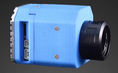
    Methane detector

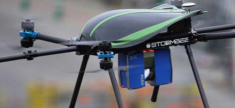
    Pergam gas sensor integrated with carbon-fiber UAV

    Pergam gas sensor aboard the Microdrones md4-1000 UAV.

    The aerial methane detector mdTector1000 CH4 detects methane gas via a fully integrated aerial package. It has a Pergam gas sensor, mounted and integrated with the Microdrones md4-1000 UAV. In real time users can see aerial shots of detection with the laser sensor. The carbon-fiber-built UAV goes into dangerous areas unsuitable for workers. The mdTector1000 CH4 can be used for natural gas line surveys, tank inspections, gas well testing, plant safety and landfill emission monitoring. The mdCockpit Android app allows users to maintain visualization in flight. A special mdTector app allows users to visualize and present all post-flight data on one map.
    Microdrones, www.microdrones.com

    UAV tracking antenna

    Portable antenna for unmanned or manned aircraft

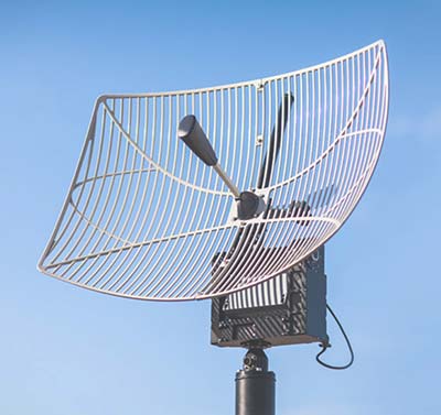
    The Octopus UAV portable tracking antenna enables long-range data transmission and is suitable for unmanned and manned aircraft applications. It has a range of more than 100 kilometers and an integrated pointing algorithm. The GPS location of the aircraft is sent over the Airlink IP datalink and received directly by the tracking antenna, making it operational with any existing unmanned aircraft autopilot system. For a manned aircraft, an existing GPS receiver or dedicated GPS receiver can be used.

    Octopus ISR Systems, octopus.uavfactory.com

    GNSS Engine

    Brings high-precision positioning and attitude to small UAVs

    AsteRx-m2 UAS receiver.

    The AsteRx-m2a UAS GNSS OEM engines provides precise and reliable multi-frequency, all-in-view real-time kinematic (RTK) positioning and heading — along with interference technology — with low power consumption. It features Septentrio’s AIM+ interference mitigation and monitoring system, which can suppress a wide variety of interferers. It is designed to bring high-precision positioning and attitude to any space-constrained application, offering a high update rate and low latency output. The AsteRx-m2a UAS provides plug-and-play compatibility for autopilot systems such as ArduPilot and Pixhawk. Event markers accurately synchronize camera shutter events with GNSS time. The board can be powered directly from the vehicle power bus via its wide-range input. It works seamlessly with GeoTagZ software, providing offline re-processed RTK accuracy without the need for either ground control points or a real-time datalink.

    Septentrio, septentrio.com


    TRANSPORTATION

    Railroad antenna

    Designed for use in congested sites

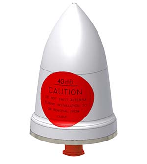
    The GPS-TMG-HR timing antennas are designed for Positive Train Control and railroad management, among other markets. They are equipped with high-rejection narrowband filtering to mitigate interference and provide 65-dB rejection of frequencies adjacent to L1 GPS. The GPS-TMG-HR maintains all features of PCTEL’s GPS timing reference platform. The antennas feature a 26-dB amplifier (GPS-TMG-HR-26N) and 40-dB amplifier (GPS-TMG-HR-40N ) and narrowband high rejection filtering to support long-lasting, trouble-free deployments in congested cell-site applications with severe interference around the GPS L1 frequency. The proprietary quadrifilar helix design, coupled with multi-stage filtering, provides superior out-of-band rejection and lower elevation pattern performance than traditional patch antennas.

    PCTEL, pctel.com

    Patch antenna

    Embedded stack passive patch

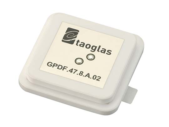
    The GPDF.47.8.A.02 is a ceramic GPS L1/L2 / Galileo low-profile, low-axial ratio, embedded stacked passive patch antenna. It is 47.5 x 47.5 millimeters wide and 8 millimeters thick. It is designed for the highest accuracy centimeter-level tracking in telematics applications for positioning technologies. Typical applicable industries are transportation, defense, marine, agriculture and navigation.

    Taoglas, taoglas.com

    Autonomy Platform

    For development of autonomous vehicles

    The Autonomy Development Platform provides automakers, truck makers and Tier 1 vehicle suppliers the hardware, software, engineering and integration services they need to accelerate development programs for on-road and off-road autonomous vehicles. By combining customized integration and engineering services with GNSS-inertial positioning technologies, the Autonomy Development Platform advances driverless vehicle development projects at every stage of development and commercialization. The platform delivers a navigation solution that is fully customizable and includes integration and engineering services, field-tested hardware and proprietary software for highly accurate positioning. The solution is capable of working with all sensors, including multiple cameras, lidar, radar and ultrasonic sensors, and with all vehicle types at all stages in the development and commercialization cycle. Also, the technology enables highly accurate assessments of the full 360-degree environment around a vehicle to produce a robust representation, including static and dynamic objects, which is critical for successful vehicle autonomy.

    Applanix, applanix.com

    Map delivery service

    Offers a customizable data stream

    TomTom AutoStream is a map delivery service for autonomous driving and advanced driver assistance systems. The service enables vehicles to build a horizon for the road ahead by streaming the latest map data from the TomTom cloud. TomTom AutoStream ensures that the TomTom map data used to power advanced driving functions is the latest, most accurate available, enabling a safer and more comfortable experience. The map-data stream can be customized based on criteria such as sensor configuration and horizon length. It can stream a wide variety of map data including advanced driver assistance systems (ADAS), attributes such as gradient and curvature, and the TomTom HD Map with RoadDNA. This flexibility allows customers to use AutoStream to power a wide range of driving automation functions.

    TomTom, tomtom.com

  • Expert Opinions: Challenges faced by multi-constellation GNSS receiver designers

    Expert Opinions: Challenges faced by multi-constellation GNSS receiver designers

    Javad Ashjaee
    President and CEO,
    Javad GNSS

    Q: What is the biggest challenge facing designers of multi-constellation GNSS receivers today?

    Javad Ashjaee, founder of Javad GNSS: The biggest challenge now is spoofing.

    Some years ago the issue was jamming —the hot issue of LightSquared — that would hurt GNSS. To solve that problem we created the J-Shield and showed that J-Shield technology could protect against LightSquared and similar signals. We manufactured dozens of units that were successfully tested by several independent laboratories.

    Now GNSS faces the spoofing issue. Reports of Black Sea spoofing and other examples show the urgency of paying attention to this problem. When a spoofer is successful, both position and time are spoofed.

    A Nov. 3 CNN video report on this subject gives an example of how little people know about spoofing and about the work that has been done on this subject. The report claims that GNSS technology companies have not done much or spent money on this subject. Obviously the reporter doesn’t know what we have done, as I will report here.

    I’ll review the spoofing methods and how we counter them.

    Source: Javad GNSS
    Source: Javad GNSS

    Spoofers use three methods: One simple way is to broadcast GNSS-like signals that provide the wrong ranging information which, when used, creates wrong position and time solutions. Most probably this is the method that Prof. Todd Humphreys used to spoof the GNSS receiver on the $80 million yacht [“GNSS Lies, GNSS Truth,” November 2014 GPS World.] This method fools the GNSS receiver into ignoring the correlation peak of the real satellite signal and using the correlation peak of the spoofer signal. To deal with this type of spoofer we take advantage of the 864 tracking channels and over 130,000 fast acquisition channels of our TRIUMPH chip. We assign more than one channel to each satellite signal and we track all their peaks: The real peak and the spoofer’s peaks. Then in Step 1, below, we exclude all signals with more than one correlation peak.

    Method Two is broadcasting spoofed signals for satellites that are below the horizon in the spoofed area or for satellites that do not exist. In this case only one correlation peak exists. Our equipment and OEM boards can download valid and certified almanac data from our website to know the status of satellites and their visibility ahead of their mission. Almanac data can be used for several weeks.

    Method Three is to cover the signal of a visible satellite with noise and on top of the noise add the spoofer signal with more power. We recognize such spoofers by their unreasonable signal power and the background noise.
    In the first counter-spoofing step we ignore these signals:

    1. Those with more than one peak;
    2. Those that according to our almanac should not be visible;
    3. Those with unreasonably high or inconsistent signal-to-noise ratio (SNR);
    4. Systems whose satellites all have similar SNR.
    5. Satellites that do not generate complete multi-frequency signals (spoofers usually generate only C/A code).

    After removing all questionable signals, we use the remaining signals to compute our approximate position. We need at least 4 signals from the many available signals of GPS L1, L2P, L2C, L5, GLONASS L1, L2, L3, and the many signals of BeiDou, QZSS and IRNSS.

    In the second step we validate all questionable signals against the approximate position that we have calculated and keep only those that pass our validation. We then re-compute the more precise position using all good signals. We consistently throw away the spoofer correlation peak and use the real satellite signal.

    If all signals of all satellites are spoofed, then we warn the user to ignore the GNSS signals and use some other sensors (like compass and gyro) to get out of the spoofed area. A spoofer that can spoof all signals of all satellites will be very expensive to build and deploy.

    In a very difficult situation, the user can enter their approximate position to quickly understand if spoofers exist, and then identify them.

    All the counter-spoofing methods that I have discussed here are the subject of patents for which we have applied.

    Since currently most of spoofers spoof the L1 C/A code, we can simply initially ignore the C/A signals to compute the initial approximate position and use it to identify the spoofed signals.

    It is vital that in areas that spoofing danger exists, users employ OEM boards that provide more satellite systems and more signals, rather than using a simple GPS C/A code, for example.

    Finally I would like to challenge Prof. Todd Humphreys [professor and director, Radionavigation Laboratory, University of Texas-Austin] to spoof any of our receivers that have this anti-spoofing option. We offer this as an option on all of our OEM boards.

  • Where is that spoofed signal coming from?

    An experiment in an anechoic chamber with a JAVAD GNSS TRIUMPH-LS shows the approximate orientation of the spoofer (at 283° azimuth.)

    Javad GNSS advises that with its equipment it is possible, when a spoofer is detected in the area, to identify the direction from which the spoofing signals are coming.

    Hold the receiver antenna horizontally and rotate it slowly (one rotation in 30 seconds) to determine the angle at which satellite energies become minimum.

    The spoofer’s direction lies behind the null point of the antenna reception pattern.

    An experiment in an anechoic chamber with a Javad GNSS Triumph-LS shows the approximate orientation of the spoofer (at 283 degree azimuth.)

  • NGS 2018 GPS on BMs program in support of NAPGD2022 — Part 5

    NGS 2018 GPS on BMs program in support of NAPGD2022 — Part 5

    My last column highlighted two components of the North American-Pacific Vertical Datum of 2022 (NAPGD2022) — the geoid undulation model of GEOID2022 and gravity model of GRAV2022. It expressed that these two models will be very important to future surveyors and mappers that are incorporating geodetic data into NAPGD2022. The last column also emphasized the significant differences between NAPGD2022 and the U.S. National Vertical Datums of NAVD 88 and NGVD 29. A year ago, my February 2017 column provided information on strategically occupying benchmarks to support NGS 2017 GPS on BM Program. The column focused on addressing the following questions: (1) Is the large GPS on BM residual due to an issue with the NAVD 88 orthometric height or the NAD 83 (2011) ellipsoid height? and (2) Should stations with large GMS on BM residuals be included in the development of NGS’ hybrid geoid models? The column provided suggestions on how users can assist NGS in determining the reason for the large difference between the modeled hybrid geoid value and computed GNSS/leveling geoid computed value. My October 2016 column demonstrated how to use the GPS on BMs dataset to identify potential issues in published NAVD 88 and NAD 83 (2011) heights. It focused on analyzing the NGS’ GPS on BM data set that was used to create NGS’ GEOID12B hybrid geoid model. It provided procedures that users could employ when analyzing the differences between the modeled geoid values and the computed geoid values using GNSS/Leveling data (GNSS-derived ellipsoid height minus leveling-derived orthometric height). The October 2016 column provided several examples of large relative differences in residuals between neighboring stations.

    It should be noted that many of these large GPS on BM residuals could be due to an invalid NAVD 88 published height because the bench mark moved since the last time the height of the bench mark was adjusted and published, and/or an undetected error in an ellipsoid height due to a weak GNSS project design. Either way, in my opinion, most of these stations with large GPS on BMs residuals don’t accurately represent a bench mark with a current NAVD 88 height (or what I call a valid NAVD 88 height). When performing a geodetic survey, these stations would be identified as bench marks with invalid heights when following the appropriate Federal geodetic survey guidelines, procedures, and specifications. These bench marks should not be used in the hybrid geoid model just like they would not be used in controlling geodetic surveys. NGS’ goal is to create a hybrid geoid model that is consistent with published valid NAVD 88 values. User participation in NGS’ GPS on BMs Program is critical to creating a hybrid geoid model consistent with a current NAVD 88.

    Recently, NGS performed a detailed analysis of the latest GPS on BMs data file using the published NAD83 (2011) ellipsoid heights, NAVD 88 orthometric heights, and the latest experimental geoid model height, xGeoid17b, to compute a new set of GPS on BMs residuals. At this time, the analysis has only included the 48 conterminous States, District of Columbia, Puerto Rico, and Virgin Islands. These data included NAD 83 (2011) ellipsoid heights from all submitted GNSS projects and OPUS Shared results. The goal of the detailed analysis was to create a statistical ranking of the marks based on a quantitative analysis of the leveling and GPS data. The following attributes were considered during the analysis:

    • Total number of GPS observations to and from the station
    • Date of last GPS observation to and from the station
    • Whether or not the GPS station has repeat baselines between closely spaced neighboring GPS on BMs stations
    • Total number of times the mark has been leveled to
    • Date of latest leveling
    • Quality of leveling (single run; double run; or single run, double simultaneous)

    The analysis of this data set was used to identify stations that should not be used in the creation of a hybrid geoid model or a NAPGD2022 Transformation tool. The stations identified as outliers and labeled as “Do Not Use” in a hybrid geoid model were based on issues associated with the NAVD 88 published orthometric height and/or the NAD83 (2011) ellipsoid height. I have described some of these issues in previous columns (August 2015 column, June 2016 column, October 2016 column and February 2017 column) so I won’t go into details in this column. NGS used the detailed analysis of the latest GPS on BMs dataset to: (1) generate a prototype hybrid geoid model to evaluate the residuals at stations not used in the hybrid geoid model, (2) confirm that the stations recommended for re-observations should be observed again, and (3) identify void areas that need additional observations.

    Since GEOID12B was created, users have been instrumental in providing OPUS results on bench marks in areas NGS said that they needed additional stations. Saying that, NGS realizes that everyone is busy and has limited resources to collect GNSS data on bench marks to support the next hybrid geoid model. NGS has used the detailed analysis to prepare material to assist users on strategically occupying stations to help support the GPS on Bench Marks Program, and create a hybrid geoid model that accurately represents a current NAVD 88. To eliminate confusion of where NGS would like new observations, NGS’ material contains a specific list of stations that they would like occupied with GNSS during the 2018 GPS on BMs program. This column provides a summary of the latest details of NGS’ 2018 GPS on BMs campaign which will be used to create the next hybrid geoid model in 2019 (see box titled “Personal Communication received from Galen Scott, Project Lead of NGS’ GPS in BM Program.”).


    Personal Communication received from Galen Scott, Project Lead of NGS’ GPS on BM Program

    In early 2019, NOAA’s National Geodetic Survey (NGS) will replace GEOID12B with GEOID18, a new hybrid geoid model to deliver improved GPS-derived NAVD 88-equivalent orthometric heights. This new model will serve as the official means for obtaining NAVD 88-equivalent heights via GPS. It will be the last hybrid geoid model that NGS will create before NAVD 88 is replaced by NAPGD2022.NGS will use available GPS on bench mark data to create the new model. Recent analysis of existing GPS on bench mark data and a prototype of the new hybrid geoid model created using that data has highlighted areas where additional data is needed to either confirm or update the local relationships between the ellipsoid, orthometric, and geoid heights.

    This email provides a prioritized list of bench marks for which additional GPS data is needed to improve the hybrid model. Data submitted on these marks will also support the development of the transformation tools that will be developed as part of the transition to the new datums.

    Data to support the hybrid geoid model will be accepted through August 31, 2018. NGS will continue to accept data to support the transformation tools through 2020. New prioritized lists of marks to support the transformation tools will be made available over the next few years as analysis of data requirements progresses.

    For the marks included in the attached document, NGS is requesting support in two ways:

    1. Attempt to locate the marks on the list and submit a mark recovery through DS World. Check this NGS page for more information on mark recovery.
    2. Collect 4 or more hours (more is better) of GNSS data on the mark following NGS guidelines, submit the data to OPUS and select the option to Share.

    More information, including training material, is available on the NGS GPS on Bench Marks (GPS on BM) website. Two matching, independent GPS observations are required for each mark. The list indicates how many observations we have so far on each mark (obs_cnt column). A tracking map showing the currently prioritized marks and the number of observations we have on each will be added to the GPS on BM website in the near future. To maximize efficiency, please check this map before observing a mark to ensure that the required data has not already been submitted.

    Please note: Marks on this list may be inaccessible, destroyed, or not GPS’able. If this is the case, please locate and observe another nearby NAVD 88 mark, within ~10 km.

    The mark list is provided in three file formats, but all contain the same information, so choose the format you are most comfortable with: excel spreadsheet, esri shapefile, and Google Earth kmz.

    The image below shows the changes between GEOID12B and the prototype hybrid geoid model. While data is needed on all the marks in the list, you may further focus your data collection efforts by looking for areas in this image that show large changes in your region.

    It is important for users to understand that NGS needs to have a high level of confidence that the OPUS Share results are accurate; therefore, they are requiring that “two matching, independent GPS observations are required for each mark.” The list of stations that they would like observed includes a count of the number of times that station has already been observed. NGS will be updating a website as stations are submitted so participants will not be wasting resources observing a station that has already been observed by someone else. It should be noted that if a station is only occupied once, it will still be useful for validating the hybrid geoid model; but stations occupied twice can be used in defining the hybrid geoid model.

    The attached file includes the list of stations that NGS would like observed to support the next geoid model. The information is provided in three different formats — excel spreadsheet, esri shapefile, and Google Earth kmz (See the box titled “List of Files for the 2018 GPS on BMs Program.”)


    List of Files for the 2018 GPS on BMs Program

    The data set also contains a folder titled “GEOID Model Changes by Region” which contains plots that depict changes between GEOID12B and the Prototype Hybrid Geoid Model (Note: at this time, NGS is denoting this prototype hybrid geoid model as GEOID18v2.2).


    List of Files from Folder Titled “GEOID Model Changes by Region”


    Figure 1 is a plot of the change between the prototype GEOID18v2.2 and GEOID12B in the Mid-Atlantic States. Looking at figure 1, the reader can see that there are some significant differences between the prototype hybrid geoid model values and the published GEOID12B values. On figure 1, all of the dark blue values are differences at the -10 cm level and the dark orange values are differences at the 10 cm level. There are several reasons for these changes including newly observed gravity data observations (especially in area with new GRAV-D data), improved data and models from satellites programs, new and improved algorithms for processing gravity data and estimating topographic effects, additional OPUS Share results in areas where GEOID12B didn’t have observations, and differences based on stations that were included in GEOID12B but rejected in the prototype model based on the latest detailed analysis.

    Figure 1 – Changes between Prototype GEOID18v2.2 and GEOID12B in the Mid-Atlantic States (units = meters).

    As previously mentioned, the list of stations that NGS would like observed with GNSS are provided in three formats: excel spreadsheet, esri shapefile, and Google Earth kmz. The box titled “Sample Data Elements Extracted from the Excel File Titled “gpsonbm_priority_list_20180205.xlsx” provides a sample of the data from the excel file. The box titled “Definition of Columns of GPS on BMs data file” provide the columns and a brief definition of the data field.

    Sample Data Elements Extracted from the Excel File Titled “gpsonbm_priority_list_20180205.xlsx”

    The priority column has two entries – A or B. Priority A is more important than priority B. In other words, if the user has to make a choice, NGS would like the priority A station observed first. The obs_cnt field will be updated as users submit their OPUS Shared results. Remember, NGS is requiring two matching, independent GPS observations for the station to be included in the development of the hybrid geoid and transformation tool.

    The near_pid provides the pid of the station that is near the original station. The selection of the near_pid was based on the original station’s position and a search of the NGS database for a station within 5 to 15 kilometers of the original station. NGS’ analysis indicated that the original GPS on BMs station may have moved so an additional observation on the same station will not help to generate a hybrid geoid model that represents the current NAVD 88. It would warp the geoid model to fit the published NAVD 88 height but if the station moved since it was last leveled to, then it does not have a valid NAVD 88 height. As previously stated, when performing a geodetic survey, these stations would be identified as bench marks with invalid heights when following the appropriate Federal geodetic survey guidelines, procedures, and specifications. The surveyor would then level to another bench mark until they met the survey’s specifications. These bench marks with invalid heights should not be used in the hybrid geoid model just like they would not be used in controlling geodetic surveys. If the near_pid column is “n-a” then NGS would like the original station observed.

    The box titled “Number of Priority Stations in Each State” provides the number of priority A and B stations for every State in the lower 48, the District of Columbia, Puerto Rico, and the Virgin Islands. Overall, there are 6082 stations in the list – 3544 Priority A stations and 2538 Priority B stations.

    Number of Priority Station in Each State

    As an example of a State in eastern United States, the box titled “List of PIDs of Priority “A” and “B” Stations in North Carolina” provides the list of priority A and B stations that need to be observed in North Carolina. The box titled “List of PIDs of Priority “A” Stations in North Carolina” provides the list of priority A stations in North Carolina. Figure 2, titled “NGS 2018 GPS on BMs Program, Priority A and B Stations in North Carolina,” depicts the locations of these stations. Figure 3 depicts the location and PID of the priority A stations in western North Carolina. Figure 4 depicts the same stations with their Obs_Cnt value.

    List of PIDs of Priority “A” and “B” Stations in North Carolina That Need to be Observed
    Information extracted from Excel File Titled “full_priority_list.csv”

    (Note: The stations in this table may not be the final list of priority A and B. The attached zip file contains the latest list of stations. The latest list was received too late to modify the table.)

    List of PIDs of Priority “A” Stations in North Carolina

    (Note: The stations in this table may not be the final list of priority A and B. The attached zip file contains the latest list of stations. The latest list was received too late to modify the table.)

    Figure 2 – NGS 2018 GPS on BMs Program – Priority A and B Stations in North Carolina.
    Figure 3 – NGS 2018 GPS on BMs Program – Priority A Stations in Western North Carolina With the PID of the Station.


    Figure 4 – NGS 2018 GPS on BMs Program – Priority A Stations in Western North Carolina With the Number of Observations.

    For completeness, I will provide an example of a region in the western United States – California and Nevada. They are larger States than North Carolina and have more Priority A stations that need to be observed. Figure 5 depicts the Priority A and B stations in California and Nevada, and figure 6 depicts the Priority A stations in California and Nevada. It is recognized by NGS that managing how these stations are observed and who does what is a monumental task. Some state agency may undertake observing all of the Priority A stations; for example, Gary Thompson, Chief of the North Carolina Geodetic Survey, has committed to observing all of the Priority A stations (personal communication). Other States have County and City surveyors that will help observe and manage the process. All of the information provided in the 2018 GPS on BMs allow individuals to sort the data in ways that meet their needs. For example, the box titled “List of Priority “A” Stations by County in California” provide the list of stations in California by county.

    Figure 5 – NGS 2018 GPS on BMs Program – Priority A and B Stations in California and Nevada.
    Figure 6 – NGS 2018 GPS on BMs Program – Priority A Stations in California and Nevada.

    It should be noted that NGS identified the priority stations based on hybrid geoid requirements. The NGS geoid team would desire a valid GPS on BMs observation every 30 km. Therefore, some of the priority A stations are in areas void of any GPS on BMs stations. There may be many reasons for this but, most likely, it’s because it’s located in an unpopulated or mountainous region of the county. Either way, it may be difficult to obtain observations at these stations. The new hybrid geoid model will be created using whatever data are available. In these void areas, the geoid will be controlled by the nearest GPS on BMs stations. There is nothing wrong with this approach. The only issue will be that it will not be possible to evaluate the relation of the hybrid geoid model and NAVD 88 in these void areas. Figure 7 depicts the priority A stations and the population of cities in Northwestern Nevada and Northeastern California. The figure indicates that these priority A stations are located in an unpopulated region of Nevada. It’s obvious why there’s no GPS on BMs in this region since nobody lives there but the geoid doesn’t depend on population. In any event, if the user can obtain an observation in these regions it will really help in creating an accurate hybrid geoid model.

    List of Priority “A” Stations by County in California

    (Note: The stations in this table may not be the final list of priority A and B. The attached zip file contains the latest list of stations. The latest list was received too late to modify the table.)


    NGS’ process for determining which stations were outliers and which stations should be re-observed involved analyzing both GNSS and leveling data from NGS’ database. The GPS on BMs residuals were computed using the procedure described in the box titled “Procedure for Computing the GPS on BMs Residuals.”

    Figure 7 – NGS 2018 GPS on BMs Program – Priority A Stations in California and Nevada. (Numbers are 2012 Population Values from Census – ESRI online)

    Figure 8 depicts the location of the GPS on BMs stations in Illinois. The box titled “Summary of Statistics for GPS on BMs Residuals in Illinois” provides a summary of the GPS on BMs residuals for the State of Illinois. The results indicate that there are 804 GPS on BMs in Illinois and the residuals range between -14.1 cm to 31.2 cm. They have a mean of 6.0 cm with a standard deviation of 4.6 cm. The table titled “Statistics for GPS on BMs Residuals in Illinois With Rejections Removed” indicates that most residuals fall between 2 and 10 cm. The box titled “Summary of Positive and Negative Statistics for GPS on BMs Residuals in Illinois” provides a summary of the statistics for the positive and negative set of residuals.

    Figure 8 – GPS on BMs Stations in the State of Illinois.

    Figure 9 depicts the GPS on BMs residuals in the Springfield, Illinois, Region. During the detailed analysis of the latest GPS on BMs dataset, the analysts identified outliers that appeared to be large relative to their neighbors. Figure 9 depicts these outliers with a “X.” Stations designated with a “X” are stations that were designated as DO NOT USE in the creation of the hybrid geoid model. Figure 9 also indicates were the analyst recommended that a station should be observed before the creation of the next hybrid geoid model. These stations are labeled as Priority A stations on figure 9. Figure 10 is an enlargement of the same area that depicts a station that was recommended to be rejected in the hybrid geoid model (PID KB0702). The stations surrounding PID KB0702 all seem to be consistent with each other (residuals in smaller blue squares) so the analyst recommended that station KB0702 be rejected. At the same time, by rejecting this station, this creates a void area that needs to be filled. Therefore, the analyst also recommended that a new station be observed here; hence, the two priority A station plotted near the rejected station. Figure 11 is a plot of another rejected station (KB1018) in the same region but, in this case, the analyst did not recommend an additional observation in the area because there was another nearby station (station in red triangle) that was consistent with its neighbors (residuals in smaller blue squares).

    Figure 9 – GPS on BMs Residuals Using xGeoid17b and Priority A Stations in Springfield, Illinois, Region (unit cm).
    Figure 10 – GPS on BMs Residuals Using xGeoid17b – An Example of a Rejection (PID KB0702) Resulting with a Recommendation of a Priority A Station (units cm).

    As previously mentioned, and provided in the box titled “Attributes Considered During Analysis,” several attributes were analyzed before making the recommendations but, typically, GPS on BMs residuals between +/- 5 cm were used to identify which stations needed to be investigated.

    Attributes Considered During Analysis

    ➢ Total number of GPS observations
    ➢ Date of last GPS observation
    ➢ Whether or not the GPS station has repeat baselines
    ➢ Total number of times the mark has been leveled to
    ➢ Date of latest leveling
    ➢ Quality of leveling

    Figure 11 – GPS on BMs Residuals Using xGeoid17b – An Example of a Rejection (PID KB1018) of an Outlier (units cm).

    This analysis is the first cut at identifying stations that should not be used in a hybrid geoid model and providing a list of specific stations that could help improve the hybrid geoid model. All new data received by the cut-off date of August 31, 2018, will be analyzed by NGS and, if appropriate, the results will be included in the next hybrid geoid model. This is a great opportunity to provide data that will help to improve the hybrid geoid model in your region. My next column will provide a status report on the 2018 GPS on BMs Program.

  • Delair offers advanced UAV for aerial surveying and mapping

    Delair offers advanced UAV for aerial surveying and mapping

    Delair, a supplier of drone solutions for commercial industries, has introduced the next-generation of its high-performance DT26X Lidar UAV.

    The DT26X is a long-range fixed-wing drone that combines highly accurate lidar sensing capabilities with an integrated high-resolution RGB (red, green, blue) camera, dramatically increasing the precision, efficiency and cost effectiveness of surveying and 3D mapping.

    The Delair DT26X lidar drone combines lidar sensing with RGB camera data to enable highly accurate and high-resolution 3D representation and measurement over large areas with minimal flights and in challenging environments. (Image: Delair)

    Details of the new model, which builds on Delair’s proven expertise in long distance, beyond visual line of sight UAV operations, were revealed at the International Lidar Mapping Forum in Denver.

    Aerial-based lidar allows for extremely detailed and accurate collection of elevation data of the ground, even in large and vegetated areas, but is typically performed with specialized, single function platforms or expensive manned aircraft surveys with long lead times.

    Camera-enabled drones offer a complementary solution for collecting imagery that can augment the lidar-based models. Most projects therefore require multiple mapping flights and separate UAVs, with initial missions using lidar sensors and subsequent flights equipped with RGB-cameras to enhance the digital rendering.

    The Delair DT26X lidar’s combined payload of a lightweight sensor and integrated camera allows the acquisition of lidar and photogrammetry data in a single flight, which drastically reduces cost and immediately provides an extremely detailed digital model of the inspected assets.

    The lidar sensor is specifically designed for UAV use, adding little weight or bulk to the Delair frame. The fully-integrated smart RGB camera enables real-time camera sensor control and in-flight photo review with automated quality checks.

    The new platform delivers increased accuracy in 3D mapping and modeling of terrain and corridors in challenging physical environments (e.g. mountainous, inaccessible by road or foot, dense vegetation) and with difficult visibility, lighting or weighting conditions.

    Its long range flying capabilities — allowing coverage of up to 2,400 square acres, communication range of 30 kilometers and 100 minutes of flight time — improve the efficiency of aerial mapping operations over large areas. As a result, the Delair DT26X lidar is well suited for uses such as environmental and land surveys, forestry monitoring, infrastructure surveillance, powerline and pipeline inspections, and road and rail construction.

    “The combination of a sophisticated lidar sensor and an industrial grade RGB camera removes the ‘either/or’ decision of choosing between lidar and imagery data acquisition for geospatial professionals,” said Chase Fly, geospatial product manager at Delair. “This is the most versatile and cost-effective UAV solution for large area, long range mapping and surveying where accuracy and detail are required. It provides the precision and visibility required by the most demanding use cases and allows data acquisition and advanced digitization not possible through terrain-based or satellite 3D mapping techniques, or with limited short-range UAVs. With this configuration, users can acquire all the data required for a colorized point cloud from a single flight, which eases the point cloud classification process back in the office, saving significant time and money.”

    New lidar sensor for more accurate mapping. The Delair DT26X lidar fixed-wing UAV incorporates the new RIEGL miniVUX-1DL lidar sensor, a specially designed device for the needs of UAV use.

    The small form factor sensor includes a downward looking and optimized field of view specifically geared for corridor mapping tasks. The wedge prism scanner construction produces a field of view of 46 degrees, and the circular scan pattern provides a very high point density and point distribution.

    It offers a high scan speed of up to 150 scans per second and a measurement rate of up to 100,000 measurements per second. It is effective in penetrating poor lighting conditions or dense foliage. The lidar sensor makes use of RIEGL’s Waveform-lidar technology, allowing echo digitization and online waveform processing. It supports multiple-target resolution of up to five target echoes per laser shot.

    “The new Delair UAV is typically the type of drone RIEGL had in mind when designing the RIEGL miniVUX-1DL, and represents another step toward completing our UAV lidar equipment product portfolio. The scanner’s specific wedge prism scanning mechanism generates a circular scan pattern, resulting in high point densities and therefore is especially well suited when deploying the scanner from fast moving acquisition platforms such as fixed-wing UAVs. The FOV (field of view) of the miniVUX-1DL is 46deg, resulting in optimized efficiency for downward-looking, linear acquisition set-ups like corridor mapping applications, for example. We are pleased to have such an innovative company like Delair as an esteemed OEM integration partner, bringing our sensing technology to key market sectors that require a flexible lidar solution,” commented Michael Mayer, managing director, RiCOPTER UAV GmbH.

    RiCOPTER UAV GmbH is a subsidiary of RIEGL Laser Measurement Systems GmbH, an international provider of technology in airborne, mobile, terrestrial, industrial and unmanned laser-scanning solutions. RiCOPTER UAV GmbH commercializes RIEGL’s turnkey lidar UAV solution and laser-scanning payloads dedicated for UAV integration.

  • Trimble acquires e-Builder to expand construction management solutions

    Trimble has acquired privately-held e-Builder, a software-as-a-service (SaaS)-based construction program management solution for capital program owners and program management firms.

    e-Builder extends Trimble’s ability to accelerate industry transformation by providing an integrated project delivery solution for owners, program managers and contractors across the design, construct and operate lifecycle, the company said.

    e-Builder manages more than $300 billion of construction project value and over 200,000 projects from some of the most influential owners in North America. Owners benefit from the e-Builder solution through improved transparency and accountability while contractors benefit from faster payments, increased productivity and improved competitive advantage.

    The e-Builder solution is uniquely designed to measure and manage every step of the capital project delivery process including planning, design, procurement, construction and operations.

    Trimble’s wide range of construction hardware and software solutions significantly improve project cost, schedule and effectiveness — beneficially impacting owners, architects, engineers and contractors. The Trimble presence in construction has two points of focus, one on civil engineering projects and the other on the construction of buildings and structures. Both will benefit from the e-Builder acquisition.

    Trimble solutions leverage constructible building information model (BIM) workflows to integrate processes, improve information fidelity, reduce rework, establish transparency and deliver higher productivity. By using Trimble technologies, contractors and owners are realizing substantial reductions in total project cost.

    The combination of Trimble and e-Builder accelerates value creation for both owners and contractors by combining e-Builder’s best practice solutions for owners with Trimble’s construction lifecycle solutions, access to contractors and global reach.

    The combined solution portfolio will accelerate the integration of field operations with enterprise needs, enabling additional productivity gains. The tangible benefits include more consistent on-time and within-budget project delivery that is enabled by improved visibility, clear accountability for outcomes and the ability to convert large volumes of disparate data into actionable workflows and measurable outcomes.

    “e-Builder has always recognized that owners play a key role in the construction lifecycle and that their influence will be key to the adoption of transformative construction technology,” said Steven Berglund, president and CEO of Trimble. “Trimble will extend its reach into the owner community by leveraging e-Builder’s presence. In turn, we intend to aggressively bring e-Builder solutions to civil and building contractors and the international market. We see a significant opportunity in leveraging data and intelligence gained through design-construct workflows across the full infrastructure lifecycle. e-Builder’s solutions and, more importantly, its organization provide a strong platform for significant growth.”

    “e-Builder’s mission is to improve project execution to make construction faster, less expensive and more reliable,” said Ron Antevy, president and CEO of e-Builder. “The addition of our solutions to Trimble’s broad portfolio extends our collective ability to best support owners and contractors with project delivery and management. e-Builder current and future customers will benefit from Trimble’s construction management expertise, culture of innovation and global reach to take e-Builder solutions to the next level.”

    The e-Builder business will be reported as part of the Buildings and Infrastructure Segment.

    Financial Terms

    The all cash purchase price of $500 million will be financed through a new $300 million credit facility and cash. The new facility has terms and conditions similar to the existing revolver with a 364 day term.

    e-Builder’s reported trailing twelve month revenue is approximately $53 million. In recent years, e-Builder’s revenue growth rate has exceeded 20 percent annually, with greater than 65 percent subscription revenue as a percentage of total revenue. The transaction is expected to be dilutive to Trimble’s first quarter non-GAAP net income per share by $0.01 per share and dilutive to full year 2018 non-GAAP net income per share by $0.02 to $0.03 per share, due to the impact of fair value accounting of e-Builder’s deferred revenue and interest expense. Trimble expects the acquisition to be accretive to 2019 non-GAAP net income per share.

    An overview of e-Builder and the strategic rationale for the acquisition is available on Trimble’s Investor Relations website. For a more detailed description of the acquisition and credit agreements see Trimble’s Form 8-K filed with the U.S. Securities and Exchange Commission (SEC) on Feb. 2, 2018.

    About e-Builder

    Founded in 1995, e-Builder is a provider of integrated, cloud-based construction program management software for top facility owners and the companies that act on their behalf.

    The company’s flagship product, e-Builder Enterprise, improves capital project execution, resulting in increased productivity and quality, reduced cost and faster project delivery.

    Since 1995, e-Builder’s technology leadership and construction industry focus have helped thousands of global companies, government agencies, and health care and educational institutions manage billions of dollars in capital programs with solutions to improve the plan, build and operate lifecycle.

    The company is based in Plantation, Florida.

  • NVIDIA Jetson takes to the sky to improve worksite visualization

    Komatsu plans to introduce NVIDIA graphics processing units (GPUs) to its SmartConstrution jobsites. The GPUs will communicate with drones from Skycatch, a Komatsu partner, which will collect 3D images, generate terrain data and “visualize” site conditions.

    Komatsu is deploying the artifical intelligence (AI) project as an extension of its SmartConstruction initiative in Japan; the drone-assisted, automated equipment service was launched to alleviate the burden of the country’s severe shortage of skilled workers.

    The company has deployed SmartConstruction at than 4,000 jobsites across the country, and the AI extension will be integrated into those sites.

    Working with NVIDIA, OPTiM Corp. — another Komatsu partner and an internet of things management software company — will provide an application to correlate terrain data to jobsite workers and construction machines for visualization.

    Enter Jetson. At the center of this collaboration is the NVIDIA Jetson artificial intelligence platform. When Jetson, which works with NVIDIA’s cloud technology, is installed in construction machines, it will be able to provide 360-degree images, enabling prompt recognition of workers and other machines nearby. The technology could potentially decrease fatalities that result from workers being struck by an object, piece of equipment or vehicle.

    Jetson will also be used with the stereo cameras installed in the cabs of construction equipment, and will recognize continuously changing jobsite conditions on a real-time basis, to better provide accurate instructions to machine operators.

    Future plans call for use not only for automatic control of devices, but also for high-resolution rendering and virtual simulation of construction and quarry jobsite operations.

  • Trimble introduces next-generation GNSS reference receiver

    Trimble has introduced its next-generation GNSS reference receiver for real-time network (RTN) applications: the Trimble Alloy GNSS reference receiver.

    With 672 channels, the continuously operating reference station (CORS) receiver provides users and operators with access to multiple constellations and signals, supplying robust and reliable reference data.

    With an IP68 rating for protection against dust and moisture, the Trimble Alloy performs even in the most rugged environments to meet the demands of professionals from the earth science, surveying, construction, mapping and agricultural industries.

    Delivering high-accuracy GNSS data to improve RTN performance and reliability, the Trimble Alloy GNSS receiver allows RTN owners and operators to:

    • Track and log all current and planned GNSS. Powered by the new Trimble Maxwell 7 GNSS dual chipsets, Trimble Alloy tracks and processes all of today’s current GNSS signals at data rates up to 100Hz, and is designed to be ready for planned signals and systems. The next generation receiver provides 672 channels for unrivaled GNSS constellation tracking including: GPS, GLONASS, BeiDou, Galileo, QZSS, IRNSS as well as the full range of SBAS.
    • Deliver absolute position monitoring. Leveraging Trimble RTX precise point positioning technology, the Trimble Alloy receiver is able to derive its position at centimeter-level accuracy in real-time. Combined with Trimble’s advanced Sentry monitoring technology, the receiver will automatically notify the operator of any status change including positional changes. The technology ensures users are receiving the most accurate correction data.
    • Realize new levels of user convenience. An all new intelligent receiver design brings an unprecedented level of usability to GNSS reference stations with the Trimble Alloy reference receiver. Featuring a tilted four-line OLED screen, Trimble Alloy displays key information without the need for scrolling through multiple menus. Dual hot swappable batteries, coupled with multiple power inputs, give users flexible installation options. Wi-Fi connectivity, multiple serial ports and remote access options allow users to configure the device easily, no matter how or where it’s installed.

    “Alloy provides a solution to address a variety of installation challenges faced by RTN owners and operators today,” said Mark Richter, marketing director of Trimble’s Advanced Positioning Division. “The receiver can track all satellite signals at the highest possible data rate while being easy to use, access and configure. All of these features make the receiver a compelling investment for owner/operators who are looking to modernize their networks or single station configurations. Trimble Alloy will carry them far into the future.”

    The Trimble Alloy GNSS reference station receiver is expected to be available in most of the world through Trimble’s Distribution Channel during the first quarter of 2018. For Asia and Latin America, the receiver is expected to be available in the second quarter of 2018.

  • ComNav’s new T300 Plus GNSS receiver provides tilt compensation

    ComNav Technology has introduced the T300 Plus GNSS receiver, an upgrade to its T300 receiver.

    Designed for demanding surveying tasks, the rugged T300 Plus GNSS features full-constellation tracking capability, tilt compensation, 4G/Wi-Fi connection, 8-GB internal memory and an easy survey workflow with Android-based Survey Master Software. It is designed to make collecting accurate data easy and fast, whether done by a beginner or experienced professional surveyor.

    As an upgrade of the T300, SinoGNSS T300 Plus combines a GNSS board, Bluetooth and adjustable TX/RX UHF, Wi-Fi and 4G modem into one rugged device. Its built-in 4G modem ensures the T300 Plus works with all kinds of CORS worldwide. Moreover, T300 Plus built-in tilt sensor supports maximum 30-degree pole tilt and keeps the compensation accuracy within 3 centimeters, and the user can check the electronic bubble on the controller for fast surveys in the field.

    With two hot-swappable batteries, the T300 Plus helps to extend working hours, the company said. The battery LEDs flash when the battery runs low; they can be replaced or charged directly while in the T300 Plus through an external power connection. Its consumer-grade battery design is compatible with the Canon LP-E6, which can be purchased in retail stores.

    https://youtu.be/HddhJXF8D3Y

    ComNav Technology also provides the T300 Plus GNSS surveying system with the Android-based R500 data collector and Survey Master software, providing for powerful and straightforward survey workflow in the field.

    The T300 Plus is now available through ComNav Technology authorized local distributors or directly through ComNav Technology.

  • 2G Robotics laser systems aid in Norwegian mine countermeasures

    The first of four ULS-500 PRO laser scanning systems from 2G Robotics has been shipped to Kongsberg Maritime for integration into the Norwegian Defence Materiel Agency’s (NDMA) newly purchased Hugin autonomous underwater vehicles (AUVs).

    The acquisition signifies the Royal Norwegian Navy’s transition to autonomous systems for mine countermeasures. During operations, Hugin AUVs will be used to complete surveys of subsea environments focused specifically on locating and identifying mines.

    The Hugin systems enable users to conduct fast and efficient operations with zero surface visibility while additionally improving safety conditions by allowing personnel to remain outside the minefield. In peacetime, the AUVs contribute to hydrographic operations.

    The ULS-500 PRO dynamic underwater laser scanner system will contribute to the detection, classification and assessment of mines. 2G’s system acquires data in real time and provides users with 3D models of targets and environments accurate to the sub-centimeter.

    The complete laser scanning system also includes the 2G Observer, an ultra-sensitive stills camera able to capture images at 12 fps, and the 2G Nova, an LED panel designed specifically for AUV integration providing almost 1,000,000 lumens.

  • Handheld launches Nautiz X9 rugged Android PDA

    Handheld launches Nautiz X9 rugged Android PDA

    Image: Handheld
    Image: Handheld

    Handheld Group has launched the Nautiz X9, an ultra-rugged enterprise handheld built for fieldwork in challenging outdoor or industrial environments. It can be used as a mobile computer, data collector or field controller, the company said.

    The Nautiz X9 offers:

    • A quad-core processor and easy-to-use Android 7 (Nougat) OS.
    • GPS/GLONASS capabilities standard.
    • Optional high-quality, high-speed 2D imager.
    • Dual cameras including 13-megapixel rear-facing with autofocus and flash, and 2-megapixel front-facing.
    • 4G/LTE Android phone functionality.
    • Google GMS for Google Maps navigation and Play Store app access.
    • A sunlight-readable 5-inch capacitive display with multi-touch sensitivity.
    • IP67 ruggedness rating for waterproof, dust-tight performance.

    The Nautiz 9 is MIL-STD 810G tested for drops, vibrations, humidity, extreme temperatures and varying altitudes.It has a fast 1.3-GHz processor with 2-GB RAM and 16-GB Flash. The 4800-mAh battery will run for a full shift, even with heavy use.

    “Adding the Nautiz X9 to our family of products reflects our commitment to bringing truly rugged field devices to market,” said Johan Hed, Handheld Group director of product management. “The Nautiz X9 also extends our wide Android offerings, which have been in increasingly high demand. GMS certification is an extra feature not always included in enterprise devices, but it has proved to be invaluable for our customers, giving them access to the full suite of Google applications. The reliability and toughness of the Nautiz X9 will bring great value to field users worldwide.”

  • Launchpad: Spoofer detection for surveyors

    OEM

    RF front-end board

    7-channel multi-GNSS multi-band for software-defined receiver

    The NT1065/66_USB3 multi-channel GNSS RF front-end board is based on NTLab’s RF ICs: NT1065 (four channels for GPS / GLONASS / Galileo / BeiDou / IRNSS / QZSS, L1/L2/L3/L5 bands) and new NT1066 (two channels for all previously mentioned GNSS signals, plus one extra-channel for IRNSS S-band). The board supports USB3 connection, allowing users to process captured satellite signals on a PC or DSP platform. The board is accompanied by comprehensive software and manuals. Features include six channels for L1/L2/L3/L5-band signals + one channel for S-band signals simultaneous reception; up to four coherent channels; IF bandwidth up to 32 MHz; acquisition of wideband signals up to 64 MHz (such as Galileo E5) by two coherent channels; USB3 interface (up to 800 Mbit/s); ability to connect four x CRPA. NTLab offers an academic discount program for universities, colleges and institutes, allowing them to purchase this powerful research tool with significant savings.

    NTLab, www.ntlab.com

    GNSS OEM RTK boards

    With rover radio for wireless applications

    Three new Tersus GNSS HRS kits feature high-precision BX305, BX306 and BX316 GNSS RTK boards. The kits consist of RTK receivers, GNSS antennas, RS05R radio station modems, radio station antennas, and related cables and converters. Embedded in the receivers are the Tersus RTK boards. They are compact-design, energy-efficient, centimeter-level accurate GNSS real-time kinematic (RTK) boards that bring high-precision positioning accuracy to the market. Different from the standard BX305/306/316 GNSS kits, the new HRS versions are equipped with the RS05R lightweight and robust UHF rover radio for wireless applications. It provides reliable data communication for demanding conditions that require a combination of stability, high performance and long-range operation. The kits can be used in a variety of applications, such as unmanned aerial vehicles (UAVs), surveying, mapping, precision agriculture, construction engineering and deformation monitoring.

    Tersus GNSS, www.tersus-gnss.com

    SURVEY & MAPPING

    Spoofer detection

    Spoofing alerts for surveyors

    Spoofer detection is now available on all JAVAD GNSS original equipment manufacturer (OEM) boards. When a receiver equipped with a JAVAD board detects more than one correlation peak for any PRN code, it warns the user of the presence of spoofing (false signals) and identifies the spoofed satellites. The receivers then switch to other signals and sensors that are not being spoofed to maintain accurate positioning. The user can also employ the receiver to try to identify the direction from which the spoofing signals are originating.

    JAVAD GNSS, www.javad.com

    Laser scanner

    Scanning range reaches 1 kilometer

    The ScanStation P50 combines all the features of the P40 plus a longer range scanning capability of more than 1 kilometer. The rugged, versatile laser scanner enables professionals to 3D capture at great distances with angular accuracy paired with low-range noise and survey-grade dual-axis compensation. The ScanStation P50 opens new business opportunities for reality-capture professionals, helping them to scan what was previously unreachable such as big mine pits, long bridges, dams and skyscrapers. With its range, the P50 enables users to scan any tall or wide infrastructure or dangerous sites from a remote and safe position. This newest member of the P-Series provides the highest quality 3D data and high-dynamic range (HDR) imaging at an extremely fast scan rate of up to 1 million points per second and ranges of more than 1 kilometer.

    Leica Geosystems, leica-geosystems.com

    TRANSPORTATION

    Smartphone data analysis

    Integrates gamification and real-time data

    Azuga FleetMobile: Standalone Smartphone Edition (SSE) is a smartphone-based solution for driver behavior monitoring, mobile timecard management and GPS tracking. Azuga FleetMobile SSE leverages data analysis components of the original Azuga FleetMobile application, including driver behavior monitoring, location-based timestamps for timecards, gamification and driver rewards, without requiring separate hardware installation via a vehicle’s OBD port. Azuga’s GPS fleet-tracking offerings feature a driver rewards program to help fleets reduce accidents by up to 70 percent. The standalone application, which works on both Android and iOS smartphones, integrates gamification and real-time data to encourage self-coaching and healthy competition. Azuga’s data science team can then leverage information about driving behaviors and combine them with route patterns, fleets’ vehicle health information and environmental factors to identify opportunities for performance improvements in fleet operations.

    Azuga, azuga.com

    Vehicle tracker

    Able to receive MobileEye ADAS alerts

    The RIFA series of full-featured GPS trackers have built-in gyro and G-sensors, and supports OBDII and J1939 protocols. In addition to 4G/3G communication, it provides options to use low-power wide-area networks (LPWAN) such as NB-IOT or LoRa, which can reduce communication costs significantly. The unique CAN-to-ADR (automotive dead reckoning) function provides accurate positioning in situations of weak GPS signals, such as driving in tunnels, indoor parking facilities, urban canyons or when GPS signal obstruction hinders positioning, without additional cabling for wheel speed input.

    Antzer Tech, www.antzer-tech.com

    UAV

    Thermal imaging payloads

    Ethernet/IP-Based connectivity

    The ThermalCapture IRnet provides an Ethernet interface for live data streaming to new and existing FLIR Tau 2 drone cores and FLIR Vue Pro/R cores. The market has increased its demand for connectivity by Ethernet, with professional drone manufacturers choosing Ethernet for communication on board UAVs. The ThermalCapture IRnet allows for real-time access via Ethernet while recording radiometric data to microSD, bringing real-time access in drone flight operations to thermal imaging data. It stores the full 14-bit radiometric thermal data on a microSD card. Real-time access remains available while radiometric data are being recorded; operators can also control the camera and settings via Ethernet. Using Ethernet also offers data privacy.

    TeAx, thermalcapture.com

    Airborne lidar mapping

    Centimeter-level accuracy for 3D mapping products

    The Think 3D Stormbee multicopter integrated with Trimble’s AP15 provides efficiency, accuracy and performance for lidar surveys from unmanned vehicles. The Stormbee is a directly georeferenced UAV lidar solution for 3D industrial mapping applications, designed to collect survey-grade spatial data more cost effectively and efficiently than static lidar. Stormbee’s 3D mapping technologies include Faro’s Focus 130 laser scanner, Trimble’s AP15 high-performance GNSS/inertial receiver, Applanix’s POSPac UAV GNSS/inertial post-processing software and Stormbee Beeflex software for lidar point-cloud generation. By using the high-performance Trimble AP15 with two antennas and the Applanix post-processing software (POSPac MMS) for georeferencing the lidar data, Stormbee provides an accurate real-time and post-mission solution for all motion variables.

    Think 3D, think3d.be

    Applanix, applanix.com