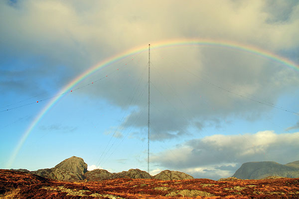
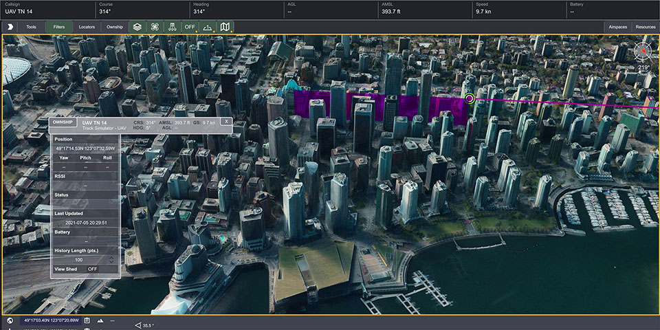
When I saw that there was a plan for a whole bunch of unmanned, semi-autonomous racecars to compete at the Indianapolis Motor Speedway (Indy, or IMS) racetrack, I initially thought we might be headed to one significant mess of broken-up machines and potentially a lot of damage. I tracked the various announcements of the competition as things progressed, especially when a prize of $1 million dollars was put up by the Lilly Endowment in Indianapolis, and the majority of the field appeared to be potentially staffed by undergrad university teams.
Photo: Indy Autonomous Challenge
However, this isn’t the first time we’ve had unmanned, autonomous road vehicles in competition — we’ve seen highly instrumented SUVs in desert settings in Nevada and California, initially with pretty poor results, which began to improve significantly for the second time round, then vehicles in some simulated street settings with some mixed and also some pretty good results.
So, as the competition date grew closer for the Indy Autonomous Challenge (IAC), the number of published progress reports began to increase, and we began to better understand how the initial 40 teams might take on this seemingly impossible task — how on Earth will they replicate a regular Indy (also a class of racecar) race? Surely many unmanned racecars on the same track at the same time doing more than 150 mph would be catastrophic!
When you take a look, however, at the advances we’ve seen, which have enabled unmanned cars, trucks, taxis and such – surely this tech could stretch to meet these major objectives? But Dallara AV-21 Indy Light racecars avoiding hurtling walls passing by, cornering, getting in and out of the pits, coping with vehicles behind, ahead and overtaking — even a superior-equipped unmanned racecar at >150 mph — well that’s something we would really need to see.
Then you have to take a look at the outfits involved, providing support to the IAC teams – companies including Cisco, and motor sport units such as ADLINK, Ansys, Aptiv, Bridgestone, Luminar, Microsoft and Valvoline and the non-profit Energy Systems Network. The University teams from around the world themselves appeared to also have significant heritage and skill-levels.
As the 40 University teams started the long trek to get over the hurdles that this challenge presented, members from 21 of those institutions were actually able to make it to Indy, grouped into nine “national” teams. By October 23 the nine teams, with only one car each, were ready to test their autonomous vehicles on the actual track.
Clemson University established the baseline Dallara AV-21 vehicle and technology to be used by each team for the race, with sensors monitoring chassis motion, suspension, tires and powertrain. Each team would install its own guidance and avoidance system, with each vehicle equipped with six cameras, four lidars, RTK GNSS, associated radios and bags of computing running each team’s customized control system software. The object being for cars to exit pit-lane, accelerate, brake, establish an optimum line for each corner and flat, avoid obstacles, evaluate the track conditions and establish tolerable limits.
The teams were required to complete several stages of selection, from submission of initial proposals through demonstration of existing vehicle automation capability, simulated race performance, qualification testing at the Indy track — all leading to an anticipated head-to head race against the other qualifiers.
Then 20 days of planned testing stretched to 50, and three months of preparation passed with students working intensely throughout, curing the glitches, experimenting with how to increase lap speed, and pushing the limits while still keeping the cars intact.
Energy Systems Network managed the rules of the final competition in a way that reflected Indy qualification days prior the main race — they judged that the technology was not yet at a stage where multiple cars on the track at the same time would have been such a good idea. So, each car was to individually run a number of practice/qualification laps and the quickest car would be the winner.
During the first stage of live competition, cars were required to exit the pits and run a warmup lap, followed by two laps that were timed and a slow-down lap that required navigating around inflatable barriers on the front-stretch, and then return successfully back around the track into their pit-stop locations. There were several spins in the corners and several crashes, but the four surviving cars/teams were able to optimistically post speeds of more than 130 mph.
Photo: Indy Autonomous Challenge
The final phase involved the four teams taking their cars around a number of warm-up/practice laps, followed by four timed laps. Only the car from Germany’s Technical University of Munich was able to complete all laps with an average speed of ~136 mph, so that team ultimately won the $1 million prize. Even so, all teams were able to successfully mature their systems’ performance through the many months leading up to the IAC and their progress through the various qualification stages. Even the other three final qualifiers had much to celebrate as a result of the competition.
The sponsors supporting the various teams as they progressed through the Challenge may have spent more than $120 million, so that high-pressure development work will be invested back into many vehicle automation opportunities. After all, that was the main objective for the whole undertaking. We should hopefully begin to see safer, more capable self-driving vehicles emerge in the months to come as the technology is applied to more production vehicle automation.
The Airbus A350 can now be equipped with the Collins Aerospace GLU-2100 multi-mode receiver. (Photo: pablorebo1984/iStock/Getty Images Plus/Getty Images)
The Collins Aerospace GLU-2100 multi-mode receiver (MMR) has received approval by Airbus, making it available as line-fit and retrofit on Airbus A320, A330 and A350 aircraft. This a major step toward Collins offering next-generation GNSS to the commercial aviation marketplace.
An MMR assists pilots in positioning, navigating and landing an aircraft. Building on the GNSS capabilities of previous MMRs, the GLU-2100 provides a satellite-based augmentation system (SBAS) and ground-based augmentation system (GBAS). This supports the integrity of the aircraft position, as well as the accuracy and availability of demanding aircraft operations such as landing in low visibility conditions.
The GLU-2100 MMR ensures that commercial aircraft can meet flight zone global mandates, while also proofing the technology by providing a solid foundation for future growth. It includes the flexible hardware baseline necessary to implement future GNSS capabilities, such as multi-frequency and multi-constellation (MFMC), and GBAS Category II/III via software-only update.
Acquisition of FlightAware tracking platform
In August, Collins Aerospace signed a definitive agreement to acquire privately held FlightAware, a digital aviation company providing global flight-tracking solutions, predictive technology, analytics and decision-making tools.
Closure of the acquisition is subject to the completion of customary conditions and regulatory approvals. Following closing, FlightAware will join Collins’ Information Management Services portfolio within the company’s Avionics strategic business unit. Financial terms of the agreement were not disclosed.
Based in Houston, Texas, with approximately 130 employees, FlightAware was founded in 2005 and is a provider of real-time and historical flight information and insights to the global aviation community. FlightAware serves all segments of the aviation marketplace through applications and data services that provide comprehensive information about the current and predicted movement of aircraft.
Through the collection, interpretation and enrichment of hundreds of sources of data, FlightAware transforms millions of raw flight data elements and delivers them as coherent, easy-to-consume flight stories. The company has a proprietary terrestrial ADS-B network with tens of thousands of receivers spanning seven continents in 200 countries and territories.
The PwrPak7-E1 from Hexagon | NovAtel is now supported on the Nvidia Drive Hyperion autonomous vehicle (AV) development platform. Selected for its robustness and precise position output, the PwrPak7-E1 will be offered with Nvidia’s autonomous driving test fleets worldwide.
Drive Hyperion is a fully operational, production-validated and open AV platform that reduces the time and cost required to outfit vehicles with autonomous driving and artificial intelligence (AI) features.
Powered by NovAtel’s OEM7 GNSS engine, the PwrPak7-E1 provides high-precision positioning used in the development of autonomous vehicles. The PwrPak7-E1 delivers NovAtel’s SPAN technology (GNSS + inertial navigation system, or INS) in an integrated, single enclosure.
Ground truth is the critical position reference for autonomous driving software behavior that can be validated. The PwrPak7-E1 provides ground truth in conjunction with Novatel’s Waypoint Inertial Explorer post-processing software. The device also has several connection options (serial, USB, CAN and Ethernet).
The GNSS and inertial measurement unit (IMU) output of the PwrPak7-E1, along with data from other onboard sensors, are recorded and fed into Nvidia’s sophisticated autonomous-driving development infrastructure and processing pipeline. There, data is synchronized, used for training AI models, and used in testing of various software components and autonomous driving behavior.
“Drive Hyperion is designed to give developers the ability to develop, evaluate, and validate AV technology more quickly,” explained Glenn Schuster, senior director of sensor ecosystems at Nvidia. “NovAtel’s compatibility on our platform provides developers the confidence to synchronize their sensor data with precision location information.”
By Brandon Weaver, Gianluca Zampieri and Okuary Osechas
Innovation Insights with Richard Langley
IT’S A FACT. GPS and its brethren global (and regional) navigation satellite systems are susceptible to outages caused by both natural and engineered events. Several reports issued in the past couple of decades have documented the vulnerability of GNSS. Twenty years ago this past August, the U.S. Department of Transportation’s John A. Volpe National Transportation Systems Center issued a report, commonly referred to as the Volpe Report, in which they found that “GPS service is susceptible to unintentional disruptions from ionospheric effects, blockage from buildings, and interference from narrow and wideband sources.” Although not explicitly mentioned in the report, besides emissions from communications systems, wideband interference can come from solar radio noise storms overpowering GPS signals. The report also highlighted that the “GPS signal is subject to degradation and loss through attacks by hostile interests. Potential attacks cover the range from jamming and spoofing of GPS signals to disruption of GPS ground stations and satellites.”
The Volpe Report recommended a number of actions to mitigate the vulnerabilities of the GPS signal to disruption or loss, including the need for backups for positioning, navigation and timing — particularly for GPS applications involving the potential for life-threatening situations such as the loss of GPS use for safety-of-life navigation, which would include, for example, aircraft navigation.
With the introduction of GPS (and subsequently the other GNSS and their augmentations) and its widespread adoption by the aviation industry, legacy navigation systems such as Omega, aviation radiobeacons, VHF Omnidirectional Range (VOR) and Distance Measuring Equipment (DME), were either shut down, reduced in their number of installations, or displaced as the primary method of navigation. These systems could not offer the same capabilities as GNSS, and that has led to the high reliance now on GNSS for getting aircraft safely from one airport to another.
But as the Volpe Report pointed out, GPS and (by inference) all other GNSS are susceptible to outages, and so a reliable alternative PNT system that can be readily used for aircraft navigation is needed. Deutsche Flugsicherung, the German air traffic control organization, has proposed such a system, called Mode N. It builds on some aspects of existing navigation systems and aviation-certified signals not originally intended for navigation, including some used for communications and surveillance.
In this month’s column, a team of researchers from the German Aerospace Center introduce us to Mode N, looking at its signal format, required ground infrastructure, aircraft avionics and the potential position accuracy this system could offer.
To accommodate the continued growth of air traffic, air navigation service providers (ANSPs) are planning and implementing programs to increase the capacity and efficiency of airspace. These programs, which include the Next Generation Air Transportation System (NextGen) led by the U.S. Federal Aviation Administration (FAA) and the Single European Sky ATM (Air Traffic Management) Research Programme (SESAR) commissioned by the European Union, heavily rely on GNSS to enable certain capabilities to reach program goals. While intended to serve as the primary source of positioning, navigation and timing (PNT) for aviation services going forward, GNSS is vulnerable to sources of interference. For this reason, efforts have been taken to identify and develop an alternative PNT (APNT) system that can maintain capabilities supported by GNSS when a GNSS outage occurs.
The ANSP for Germany, Deutsche Flugsicherung (DFS), has proposed a concept for such a system that they call Mode N. The proposed design leverages current navigation and surveillance technology to provide a completely new solution to navigation. As the current APNT environment is filled with a variety of proposed solutions spanning the entire field of communications, navigation and surveillance (CNS) technologies, it is useful to describe Mode N within the context of these other APNT systems. This contextual description serves to highlight the interaction of Mode N with current aviation systems — an important consideration for any system intended to serve aviation users. Additionally, as the Mode N design uses similar technological principles as other navigation and surveillance systems, the extensive research performed for APNT can be applied to the Mode N design to provide a preliminary assessment of its navigation performance over Germany.
Development of APNT
The current state of aviation navigation can be simplified by acknowledging that GNSS has replaced legacy navigation systems such as Distance Measuring Equipment (DME) and VHF Omnidirectional Range (VOR) beacons as the primary method of navigation for aircraft. GNSS PNT services enable many capabilities in the airspace that are relied upon by modernization efforts to accommodate the expected increase in air traffic in a safe and efficient manner. Because of GNSS vulnerabilities outlined in the 2001 Volpe Report, it was recognized that an alternative system that could enable the same capabilities as GNSS would be necessary to continue safe and efficient operation of airspace as envisioned if GNSS is unavailable.
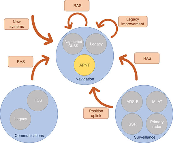
Proposed APNT solutions are generally sourced from the existing CNS environment. A common strategy is to use an aviation-certified signal not originally intended for navigation, which we have termed repurposed aviation signals (RAS). Other proposals include improving legacy systems, transmitting the ground-computed position to an aircraft, and creating new systems entirely. These sources of APNT are summarized in FIGURE 1 with explanations of the abbreviations to follow.
FIGURE 1. Sources of APNT for navigation. (Image: Weaver et al)
A natural candidate for APNT is the use of existing non-GNSS navigation infrastructure. Prior to GNSS, VOR beacons providing beacon-relative heading information and DME navaids supplying two-way range information were the primary navigation infrastructure. Improvement in DME avionics enabled tracking of multiple DME stations, providing a DME-only position solution referred to as DME/DME. Adding DME ground stations and upgrading existing hardware to increase accuracy and coverage of DME/DME positioning was therefore an attractive APNT option.
Another option sourced from the existing navigation infrastructure was to use RAS for positioning. One such RAS is that of the DME reply signal to a non-existent aircraft. By triggering DME responses in a desired fashion, aircraft can use the triggered responses for passive ranging without any change to the DME ground stations.
Communication systems for aviation are also undergoing modernization efforts. Future communication systems (FCS) are being developed to provide broadband communication capability between aircraft and controllers.
Surveillance is the domain of ground-based systems that determine the position of remote objects and is fundamental to allowing safe spacing of aircraft. Its origins reside in the development of primary radar, which was then complemented with secondary surveillance radar (SSR). Both primary radar and SSR use a rotating antenna to measure range and bearing to determine the location of the remote objects. Radar systems tend to be clustered around airports, limiting their area of coverage. To expand coverage in challenging terrain where radar is difficult to install, a technique known as multilateration is used, where a surveillance ground system can receive a signal from an aircraft and determine its position by comparing the time of arrival (TOA) of the signal between its ground stations. These systems were considered as a source of APNT by providing the aircraft position computed on the ground back to the aircraft via data uplink, but timely authentication and integrity concerns have stalled this approach in the United States.
Surveillance RAS for APNT. The other branch of surveillance-sourced APNT is by using RAS, and this is very relevant to the design of Mode N. The system providing many of the RAS for navigation is ADS-B. With this service, an aircraft broadcasts its GNSS-derived position (ADS-B Out) to ground-based stations and any aircraft capable of receiving ADS-B transmissions. ADS-B is an important part of airspace modernization strategies; it is mandated for aircraft operating in most U.S. airspace, with European mandates following suit. ADS-B ground stations, referred to as ground-based transceivers (GBT) or radio stations (ADS-B RS), collect ADS-B Out messages for use by air traffic operators. These ADS-B RS also provide their own transmissions for use by aircraft that can receive ADS-B broadcasts (ADS-B In capability) and include weather information, nearby air traffic and so on.
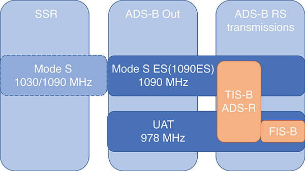
ADS-B can use different protocols to transmit its signals. The Mode S (S for selective) protocol was designed to allow SSR ground stations to selectively interrogate aircraft in their coverage area, reducing congestion on the reply frequency. The Mode S reply format consists of a four-pulse preamble and a data block containing either 56 or 112 information bits for the aircraft to provide information dependent on the interrogation received. Mode S is internationally standardized, and an extended format known as Mode S Extended Squitter was adopted for Automatic Dependent Surveillance Broadcast (ADS-B) services. Mode S Extended Squitter or 1090ES (as it’s transmitted exclusively on 1090 MHz) is also used by the ADS-B RS that rebroadcast ADS-B Out (ADS-R) and provide traffic information services (TIS-B) to nearby aircraft with ADS-B In capability.
Another protocol, used in the United States, is the Universal Access Transceiver (UAT) format. Like 1090ES, UAT is used by certain aircraft to transmit their ADS-B Out messages. Similarly, ADS-B RS transmits TIS-B and ADS-R messages with the UAT protocol; it also includes additional information that it transmits with the Flight Information Service – Broadcast (FIS-B). UAT signals are transmitted in the United States on an unused DME channel frequency of 978 MHz. FIGURE 2 summarizes the relationship between these surveillance signals and the services that use them.
FIGURE 2. Services using Mode S and UAT signal formats.(Image: Weaver et al)
Research investigating the ground-transmitted (ADS-B RS) 1090ES and UAT signals for ranging measurements greatly supports the assessment of Mode N presented here, as the Mode N system operates on a similar basis with a signal that blends characteristics of 1090ES and UAT.
Mode N Overview
Mode N (N for navigation) is a passive ranging system concept from DFS that seeks to provide APNT while reducing the spectrum congestion caused by existing aeronautical navigation and surveillance systems. The design includes the possibility for two-way and air-to-air ranging, but this overview focuses on the preferred passive mode of operation. It is designed around the Mode S format, which as mentioned, is used for SSR and ADS-B services. Despite early references to an SSR/N system, Mode N is not a new SSR mode but rather a new navigation system.
The basic concept is for Mode N ground stations to transmit on a single frequency signals that include ground station ID/coordinates, allowing aircraft with Mode N avionics to receive those signals and determine position in a similar manner to GNSS. As a single frequency is desired to minimize spectrum usage, the ground stations would space their transmissions apart to avoid intersystem interference. This scheme, known as time division multiple access (TDMA), would require information within the signal message on the scheduled time a ground station transmits, which the Mode N format allows.
Because Mode N shares many design aspects with Mode S, DME and other surveillance RAS, it is able to leverage previous APNT work for the benefit of its own analysis. Therefore, the overview of the design is described here relative to other APNT systems, as this is the basis of the preliminary performance assessment we present.
The Mode N Signal. The Mode N design proposes using the Mode S downlink signal format as the basis for its ranging signal to be used by the aircraft for passive position determination, with some key differences. The frequency channel on 1090 MHz is too congested to accommodate more signals; thus, the first difference is that Mode N intends to transmit on a different frequency. While the channel selection is still ongoing, unused DME channels have been identified as options for frequency allocation.
The second difference is the message content. As the Mode S downlink format transmits mainly aircraft-specific information, Mode N ground transmitters would instead populate their messages with information needed for passive ranging: ground station coordinates and time of transmission (TOT). The study of 1090ES messages (which also contain aircraft-specific information despite being transmitted by ground stations) as RAS required some special techniques to first identify which station was transmitting the message. The TOT is not present in 1090ES signals, but more importantly the time of transmission is not synchronized to any consistent reference. Aside from transmission frequency and message content, the Mode N signal design follows the Mode S downlink format (modulation, pulse shape and so on).
The Mode N signal also shares some aspects with the UAT signal, particularly the FIS-B segment. First, UAT is also transmitted in the United States on an unused DME channel. The FIS-B message, which provides weather information, transmits the ground station coordinates and information that can be used to estimate the TOT. Specifically, UAT messages are synced to UTC, and each ADS-B RS has a designated time slot within a one-second interval where it transmits its FIS-B message. This time slot is included in the message, and can be used to determine the TOT of the signal. Mode N is designed to work in this exact manner, minus the weather information. One crucial difference between UAT and the Mode N design is the type of modulation. Like Mode S, Mode N proposes using pulse-position-modulation (PPM) or on-off keying (OOK). The resulting wider bandwidth — estimated to be less than 4.6 MHz at –3dB — has better resistance to multipath, whereas UAT is frequency modulated to maintain a narrow bandwidth to avoid interference with DME and is more susceptible to multipath. Research on UAT signals for pseudoranging capability (also determined at a higher update rate than once per second) would be necessary for navigation, an important consideration for the final Mode N design.
Ground Infrastructure. The Mode N design, while based on RAS from the surveillance capability, requires new ground stations to transmit the Mode N signal. Requirements for the ground stations are that they provide adequate coverage to meet the requirements of an APNT system and that they are sufficiently synchronized in time. An initial time-synchronization scheme is the use of a radio frequency (RF) network consisting of the ground stations themselves, which requires radio line-of-sight of stations throughout the network. DFS performed a study and found that additional time-beacon stations would be necessary to maintain this RF time network, even though navigation coverage was provided using existing DME sites as hypothetical Mode N stations. Since these aspects of the design are still developing, the preliminary assessment we present assumes a network layout and time synchronization tolerance. As the Mode N design blends various CNS principles, a natural baseline design for the ground station locations consists of existing DME and surveillance sites in Germany. Using these locations for the ground stations enables computation of a horizontal dilution of precision (HDOP) at discrete locations throughout Germany. The assumed time synchronization is discussed further when developing a model of the Mode N ranging accuracy.
Avionics. An interesting aspect of the Mode N design is its proposed avionics unit. The Mode N avionics must be capable of receiving Mode N messages, which it can do with the existing DME antennas on aircraft. The Mode N avionics unit must then decode the messages for position determination. Its active mode for two-way and air-to-air ranging would require the Mode N avionics to transmit Mode N messages, again using the existing DME antenna.
Recognizing the continuing investment in the DME network by multiple countries, the Mode N avionics sensor is essentially built around a fully functional DME unit. This is intended to provide a seamless transition as Mode N stations are brought on line. The design of the avionics has little effect on the coverage assessment, aside from guaranteeing a minimum level of performance based on the current DME network, but is an important part of the implementation strategy. Furthermore, this blend of avionics has also been proposed for a unit compatible with DME and ADS-B (1090ES and UAT) signals.
Preliminary Coverage Assessment
Preliminary coverage assessments are a typical method to determine the feasibility of a proposed system to provide the required level of performance over a given area. A simple method of characterizing the position performance is in terms of the linear relationship between range error and DOP, where the range errors are assumed to be zero-mean, uncorrelated, and have identical distributions.
As the aircraft is assumed to have additional sensors for determining its altitude, HDOP is commonly used to characterize the expected horizontal position performance.
With range measurements, HDOP is a function of the transmitter geometry available to an aircraft at a given point. It is a straightforward computation to perform for a grid of points over the area of interest. The HDOP computation does depend on the type of range measurement, so passive (pseudo-) range, two-way range, and time difference of arrival (TDOA) measurements all have their corresponding DOP computation. Determining a model for the range error is less straightforward, and assessing the coverage potential of Mode N requires an estimation of the expected range error.
Modeling Mode N Range Accuracy. As Mode N is not an existing system, abundant quantities of real measurements are unavailable for empirically characterizing the range performance. However, since Mode N is heavily based on the Mode S signal format and functions similarly to the DME and UAT signals, which all exist and have been measured extensively, research investigating those signals can help derive the model for the Mode N range performance.
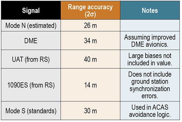
An alternate approach is to reference the standards for a specified performance level. For example, ICAO documentation specifies that the Airborne Collision Avoidance System (ACAS) logic use a zero-mean normal distribution range error model with a standard deviation of 50 feet, or about 15 meters. As ACAS also uses the Mode S signal format, this appears to be a reasonable source for the Mode N range error. However, since ACAS is an airborne two-way surveillance method, it does not exactly translate to a ground-based passive TDOA system such as Mode N. The 15-meter standard deviation is still useful, as it provides a check on the estimated Mode N accuracy. Other specifications suffer from similar drawbacks — Mode N does not directly apply to any single system. Thus, we apply the blended approach using previous APNT research.
The fundamental measurement for the passive ranging mode of Mode N is the TDOA between pairs of ground stations. This measurement is in seconds, and is translated to a range difference by using the speed of radio signal propagation in a vacuum. (See our conference paper for further details.)
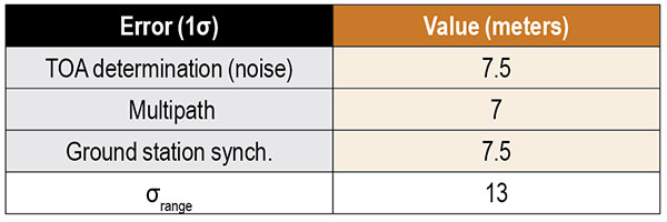
Errors can be present in the TOA measurement, synchronization of the nominal TOT of the signals, and parsing of the time slot data field. The TOA measurement can have errors by inaccurate determination of the actual TOA due to noise or multipath and by the actual TOA differing from the nominal arrival time of the signal due to atmospheric delay. For terrestrial systems, propagation errors are considered to be dominated by multipath, so we don’t consider atmospheric effects here. Time synchronization errors are very important to the ranging accuracy, but it is assumed the time slot data field is parsed accurately. Other sources of error, such as inaccurate ground station coordinates, can affect the position error but have no effect on the range error. Additionally, the error originating from the change in aircraft position between reception of signals at ground stations is not considered in this article. The model of range accuracy can then be expressed as the root-sum-square (RSS) of the dominant individual error components.
We studied each error component in isolation, selecting the applicable APNT research to leverage based on the Mode N design aspect that most corresponds with that error.
Since the Mode N design also uses a pulsed signal, the evaluation of DME (specifically, DME/N) ranging performance is the starting point for estimating the TOA noise error. Part of the APNT effort was evaluating current DME performance, as it was thought it exceeded the specified performance in standards. A study found that current DME performance allowed a budgeted TOA error of 15 meters, 2σ.
For the Mode N error model, a 7.5-meter error is an attractive option to choose as it is the average of two other sources and is the most recent. This value is a conservative estimate of the TOA accuracy for Mode N because the Mode N/S pulse shape is narrower than the DME pulse with a greater bandwidth, improving theoretical accuracy. For the preliminary coverage assessment, a conservative estimate is desired, because the actual TOA accuracy will vary over an area depending on transmitter distance — which impacts the level of signal noise. Note that the DME TOA errors are not divided by two as is done for the total DME error as they apply to a one-way TOA measurement.
After assessing the relevant studies, we modeled the multipath component of the error following that from Mode S as 7 meters, 1σ.
The final error component to estimate for Mode N is that of the synchronization of the ground stations. Based on the results from studies of the UAT signal and those from eLoran, we set a 15-meter maximum bias as a 2σ error component in the Mode N error model.
Our error analysis is summarized in TABLE 1.
TABLE 1. Predicted Mode N range accuracy. (Data: Weaver et al)
A total 2σ error for current DME performance of 92 meters has been established, which translates to 46 meters of range accuracy after dividing by two (since the DME signal is a two-way range). A substantial part of this error derives from the avionics bias, which is minimized for a “potential” DME error budget due to an assumed improved avionics performance. This results in a DME range 2σ error of 34 meters. We chose this value to compare as the effect of avionics has less of an impact in a passive ranging system such as Mode N.
Range performance for UAT signals was evaluated with measurements showing 20-meter (1σ) error when compared to GNSS truth, not including large biases attributed to ground station synchronization or processing errors. The 1090ES signals do not have an inherent ranging capability, so the TDOA measurement error of two ground station signals to one receiving station is difficult to measure. Instead, researchers have measured the differential TOA (DTOA) of one ground station signal received by two (GPS-synchronized) receiving stations to first identify which station transmitted the signal. When compared to the true DTOA based on ground station and receiving station coordinates, the measurements contained small biases around 10 meters with a standard deviation also less than 10 meters. Being DTOA measurements, these do not contain ground station synchronization errors, so the reported standard deviations correspond mostly with propagation and determining TOA. The 10-meter DTOA 1σ error can still be converted to a range error resulting in 14 meters (2σ). These results are summarized in TABLE 2.
TABLE 2. Comparison of Mode N with other APNT signals. (Data: Weaver et al)
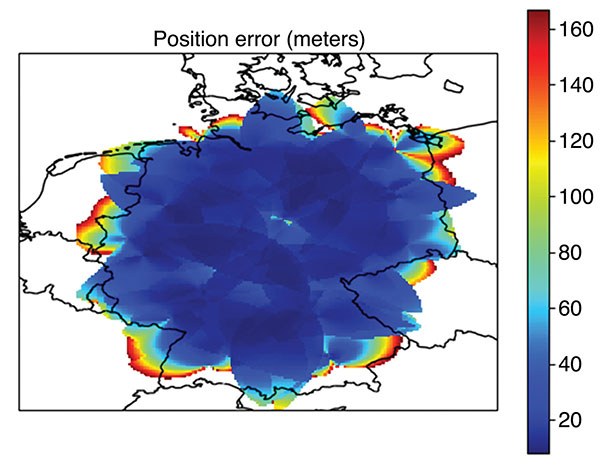
Coverage Assessment. With the estimated ranging accuracy, a preliminary coverage over Germany could now be assessed. Using the current 29 surveillance site locations in Germany and assuming that a minimum of three stations is necessary for positioning, the estimated position accuracy is shown in FIGURE 3.
FIGURE 3. Estimated position error (in meters) for aircraft within a 100 nautical mile coverage radius using existing surveillance sites as installation locations for Mode N ground stations. (Image: Weaver et al)
The coverage assessment used a “flat” Germany model with the estimated range accuracy from the preceding section (13 meters, 1σ). Atmospheric and terrain considerations were not applied in the assessment. It is important to note that this level of coverage would degrade at lower altitudes.
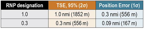
To determine whether this level of accuracy is sufficient for the airspace modernization efforts in Europe, the desired Required Navigation Performance (RNP) accuracy requirement must be examined. For RNP 1.0, where 1.0 refers to the required 95% or 2σ total system error (TSE) accuracy in nautical miles, the position error allocation is assumed to be 30% of the RNP/TSE value. The required position accuracy is shown in TABLE 3.
TABLE 3. RNP required horizontal position accuracy. (Data: Weaver et al)
From Figure 3, aircraft at altitudes within the service volume supported by a 100-nautical-mile coverage radius are capable of meeting the accuracy requirement for RNP 1.0 and 0.3 within most of Germany. Coverage along the border is unavailable as only German surveillance site locations were used.
Conclusions
Although our derivation of accuracy and the coverage assessment method we used made several simplifying assumptions, the results indicate that Mode N has the potential to be a feasible APNT system. To be a part of the modern airspace navigation infrastructure, additional accuracy requirements must also be met. The integrity requirement is harder to meet than accuracy, and requires either redundant information available to the aircraft for a receiver autonomous integrity monitoring-like algorithm or a ground-based monitoring/augmentation system. Perhaps the biggest challenge to implementing the Mode N infrastructure is maintaining an RF-based time synchronization network. Convincing aircraft operators to update their avionics is another challenge to Mode N implementation, although the inclusion of DME functionality in the Mode N avionics seeks to ease that transition.
DISCLAIMER
The views expressed herein are those of the authors and are not to be construed as official or reflecting the views of Deutsche Flugsicherung.
ACKNOWLEDGMENT
This article is based on the paper “An Overview of the Proposed Mode N System in the Context of Alternative Position, Navigation, and Timing (APNT) Development” presented at ION ITM 2021, the virtual 2021 International Technical Meeting of The Institute of Navigation, Jan. 25–28, 2021.
BRANDON WEAVER is a researcher at the German Aerospace Center (DLR) and works on alternative navigation systems.
GIANLUCA ZAMPIERI joined the Alternative Navigation Systems Group at DLR’s Institute for Communication and Navigation in 2019.
OKUARY OSECHAS leads the Alternative Navigation Systems Group in the Institute of Communications and Navigation at DLR.
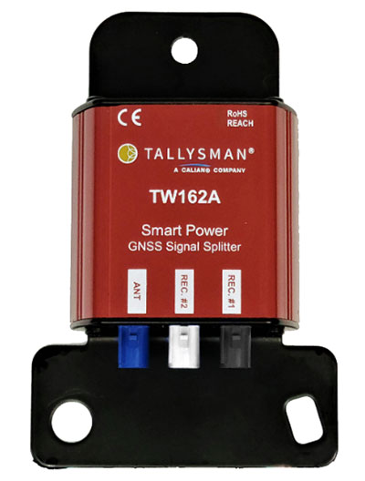
Tallysman Wireless Inc. has added the TW162A automotive-grade smart power GNSS signal splitter to its line of GNSS accessories.
The Tallysman TW162A signal splitter supports the full GNSS spectrum: GPS/QZSS-L1/L2/L5, QZSS-L6, GLONASS-G1/G2/G3, Galileo-E1/E5a/E5b/E6, BeiDou-B1/B2/B2a/B3, and L-band correction service frequency band.
Vehicle rooftop antenna space is often at a premium, and mission applications often require more than one GNSS receiver. The TW162A supports this use case where one GNSS antenna provides the signal to two GNSS receivers.
It also offers key fail-over and fault-identification features.
First, the splitter accepts power from all attached GNSS receivers; if one receiver fails, the next attached receiver automatically provides power to the splitter and antenna.
Second, if the antenna fails and does not draw current, all connected receivers will sense a current draw lower than 1 mA, indicating an antenna fault.
The TW162A offers high performance in terms of noise figure, isolation and linearity. TW162A is built with Automotive Electronics Council AEC-Q100 certified components, ensuring a wide operational temperature range and a long service life. It has been rigorously tested and is packaged in a durable, compact and lightweight aluminum housing.
The TW162A is available with three Z or A+B+C FAKRA connectors.
Though marvelous, GNSS are also highly vulnerable. eLoran, which has no common failure modes with GNSS, could provide continuity of essential timing and navigation services in a crisis.
GPS fits Arthur C. Clarke’s famous third law: “Any sufficiently advanced technology is indistinguishable from magic.” Yet, it also has several well-known vulnerabilities — including unintentional and intentional RF interference (the latter known as jamming), spoofing, solar flares, the accidental destruction of satellites by space debris and their intentional destruction in an act of war, system anomalies and failures, and problems with satellite launches and the ground segment.
Over the past two decades, many reports have been written on these vulnerabilities, and calls have been made to fund and develop complementary positioning, navigation and timing (PNT) systems. In recent years, as vast sectors of our economy and many of our daily activities have become dependent on GNSS, these calls have intensified.
A key component of any continent-wide complementary PNT would be a low-frequency, very high power, ground-based system, because it does not have any common failure modes with GNSS, which are high-frequency, very low power and space-based. Such a system already exists, in principle: it is Loran, which was the international PNT gold standard for almost 50 years prior to GPS becoming operational in 1995. At that point, Loran-C was scheduled for termination at the end of 2000.
However, beginning in 1997, Congress provided more than $160M to convert the U.S. portion of the North American Loran-C service to enhanced Loran (eLoran). In 2010, when the U.S. Loran-C service ended, its modernized and upgraded successor was almost completely built out in the continental United States and Alaska. During the following five years, Canada, Japan, and European countries followed the United States’ lead in terminating their Loran-C programs.
Today, however, eLoran is one of several PNT systems proposed as a backup for GPS.
The National Timing Resilience and Security Act of 2018 required the Secretary of the U.S. Department of Transportation (DOT) to “provide for the establishment, sustainment, and operation of a land-based, resilient, and reliable alternative timing system” as a backup to GPS. In January 2020, the DOT awarded contracts to 11 companies to demonstrate their technologies’ ability to act as a backup for GPS. Of these companies, two were working on eLoran projects.
Technical advisers to the federal PNT Executive Committee have been advocating and recommending that the government implement eLoran for the past 11 years. Yet, while the U.S. government announced in 2008, and again in 2015, its intention to build an eLoran system, it has not done so yet.
Not Your Grandfather’s Loran
In the 1980s, I used Loran-C to navigate on sailing trips off the U.S. East Coast. It had an accuracy of a few hundred feet and required interpreting blue, magenta, black and green lines that were overprinted on nautical charts. The system was a modernized version, launched in 1958, of a radio navigation system first deployed for U.S. ship convoys crossing the Atlantic during World War II. Its repeatability was greater than its accuracy: lobster trappers could rely on it to return to the same spots where they had been successful before, though they may have had some offset from the actual latitude and longitude.
By contrast, eLoran has an accuracy of better than 20 meters, and in many cases, better than 10 meters. It was developed by the U.S. and British governments, in collaboration with various industry and academic groups, to provide coverage over extremely wide areas using a part of the RF spectrum protected worldwide. Unlike GNSS, eLoran can penetrate to some degree indoors, under very thick canopy, underwater and underground, and it is exceptionally hard to disrupt, jam or spoof.
Unlike Loran-C, eLoran is synchronized to UTC and includes one or more data channels for low-rate data messaging, added integrity, differential corrections, navigation messages, and other communications. Additionally, modern Loran receivers allow users to mix and match signals from all eLoran transmitters and GNSS satellites in view.
Finally, eLoran can be used for integrity monitoring of GPS — and vice versa. “Think of a resiliency triad, consisting of GNSS (global), eLoran (continental), and an inertial measurement unit, a precise clock, or a fiber connection,” said Charles A. Schue, CEO of UrsaNav. “It is extremely difficult to jam or spoof all three sources at the same time, in the same direction, and to the same amount.”
For the eLoran system to cover the contiguous United States, between four and six transmission sites could provide overlapping timing coverage, and 18 transmission sites could provide overlapping positioning and navigation.
U.S. Developments
The INVEST in America Act authorizes $157 million for the Department of Homeland Security to conduct research in five separate areas, one of which is positioning, navigation and timing resiliency; however, none of this money is for eLoran per se. The regular DOT appropriation for next year has $17 million for PNT-related research, $10 million of which is for “GPS Backup/Complementary PNT Technologies Research.” However, neither of these bills has yet been finalized, let alone passed into law, so they may change.
“These are very complex systems, with five- to seven-year sales cycles,” pointed out Schue, “and the process is even slower now due to the pandemic. With adequate funding, eLoran signals could start becoming available in the contiguous United States within a year of a service contract being signed. We should recall that GPS — as, indeed all of the GNSS — was brought online gradually as satellites were developed and launched into space. There should be no expectation that any other nationwide system would be available at the flip of a switch instead of through gradual implementation.”
the former Loran-C transmission antenna at Værlandet, Norway. (Photo: UrsaNav)
International Developments
Loran-C and eLoran operate internationally. Saudi Arabia, China and Russia continue to operate Loran-C or Chayka systems. In October 2020, a Chinese paper described how the nation is expanding Loran to its west to cover the whole country to protect itself from disruptions of space-based services. A previously published report made it clear that they are upgrading or have upgraded from Loran-C to eLoran. South Korea has an ongoing project to upgrade its Loran-C to eLoran. It also seems the project will ensure that the South Korean system will be useable on its own, even if the Russian and Chinese systems with which it normally cooperates are not available for some reason, according to Dana Goward, president of the Resilient Navigation and Timing Foundation.
The United Kingdom is still committed to eLoran, and operates one station that has been used as an alternative time reference to GNSS. “However, as the sole station still transmitting in that area of Europe it’s of no use for positioning,” said Nunzio Gambale, CEO of Locata Corporation. “Unfortunately, the EU’s shutdown of their old Loran sites seems to have been completed, and no EU-based Loran sites remain operational. Their actions leave scant hope for Loran’s resurrection any time soon as an alternative to GNSS positioning in Europe. That’s a shame, because eLoran has beneficial PNT characteristics that other alternate technologies will struggle to replicate.”
A deck officer on a ship takes a relative bearing using a pelorus. Loran-C was developed in large part for maritime navigation. (Photo: aytugaskin/iStock/Getty Images Plus/Getty Images)
Advocacy
“There is fairly good agreement across the PNT community that there is no sole solution [to GPS vulnerabilities],” Schue said. “It needs to be a system of systems.”
The PNT community, he said, is working with Congress and the administration “to move ahead with actual RFPs to start the contracting process — instead of continuing to admire the problem.” UrsaNav, NextNav, OPNT and other companies and organizations “are working together as best as we can to tell the federal government that we all believe in a system-of-systems approach and that there ought to be some tangible forward motion.”
While DOT has the lead on providing PNT resiliency, it and the departments of Defense and Homeland Security need to cooperate on this, Schue argued. “Many, if not all, of the other departments — such as Commerce, Energy, State, Interior and Agriculture — also have a stake.”
GNSS will remain for a reason. “Unless a new national terrestrial PNT system moves the game forward for many markets, it’s just far too easy to remain with the GNSS system, which is fundamentally free,” Gambale said. “That’s a really difficult price point to compete with, unless you’re delivering significant new value to the market.”
The time to act is now. “This issue has been studied to death for more than 20 years,” Goward said. “There are technologies ready to deploy. It is time for action. A failure of national PNT will be catastrophic.”
A roundup of recent products in the GNSS and inertial positioning industry from the November 2021 issue of GPS World magazine.
OEM
Simulator
Designed for desktop convenience
Photo: Orolia
The BroadSim Solo has a compact form factor designed to fit comfortably at a typical desk or workstation. It shares the same Skydel simulation engine that runs on a standard BroadSim, BroadSim Anechoic and BroadSim Wavefront. It supports advanced scenario creation features and the benefits provided by a software-defined architecture such as high dynamics, a 1000-Hz iteration update rate and ultra-low latency of 5 ms. Nearly all civilian GNSS signals can be generated through the Solo’s single RF output (one frequency band at a time), along with jamming or spoofing signals, and GPS AES M-code.
Series offers GNSS, 5G NR, and wifi-6E combination
Photo: 2J Antennas
The Stellar series of antennas is designed for a large suite of devices with a focus on GNSS, sub-6 GHz, 5G NR, 4G LTE, 3G, 2G and WiFi-6E technologies. The series is suitable for law enforcement, medical transportation, fire rescue and other mission-critical applications. The series includes single or up to 9-in-1 configuration choices within the range of 617 MHz to 7125 MHz frequency bands. The patent-pending technology reduces the antenna footprint by 55% while implementing a new double trifilar design and longitudinal resonances for MIMO/ARRAY configurations that traditionally have more complex size restrictions (such as B71 band/600 MHz). Each antenna configuration uses symmetrical or asymmetrical resonators for negative sections of the antenna, resulting in maximum performance at low and mid frequencies.
The full-band GNSS HC990E embedded helical antenna is designed for precise positioning, covering the GPS/QZSS-L1/L2/L5, QZSS-L6, GLONASS-G1/G2/G3, Galileo-E1/E5a/E5b/E6, BeiDou-B1/B2/B2a/B3, and NavIC-L5 frequency bands, including the satellite-based augmentation system (SBAS) available in the region of operation [WAAS (North America), EGNOS (Europe), MSAS (Japan), or GAGAN (India)], as well as L-band correction services. The HC990E embedded helical antenna is designed and built for high-accuracy positioning. It is packaged in a very light and compact form factor, making it suitable for a wide variety of applications, especially lightweight UAV navigation. The HC990E is 60-mm wide and 25-mm tall, weighing 12 grams. It features a precision-tuned helical element that provides an excellent axial ratio and operates without the requirement of a ground plane. The HC990E also features a low-current, low-noise amplifier (LNA) and pre-filter to prevent harmonic interference from high-amplitude signals, such as 700 MHz band LTE and other nearby in-band cellular signals.
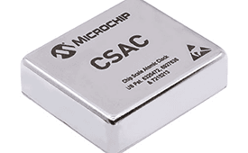
The SA65 chip-scale atomic clock (CSAC) provides precise timing accuracy and stability in extreme environments. Designed for military and industrial systems, it features ultra-high precision and low power consumption. The SA65 CSAC delivers higher performance than the previous SA.45s CSAC, including double the frequency stability over a wider temperature range and faster warm-up from cold temperatures. It has an operating temperature range of –40° C to 80° C and a storage temperature range of –55° C to 105° C. The warm-up time of two minutes at –40° C is 33% faster than that of the SA.45s. These performance improvements benefit designers of highly portable solutions for military applications such as assured positioning, navigation and timing (A-PNT) and C5ISR (command, control, communications, computers, cyber, intelligence, surveillance and reconnaissance).
Samsung Electronics is offering a new processor for wearables, the Exynos W920. The new processor integrates an LTE modem and is built with an advanced 5-nanometer (nm) extreme ultraviolet process node, offering powerful yet efficient performance demanded by next-generation wearable devices. The Exynos W920 is embedded with a GNSS L1 receiver (GPS, GLONASS, BeiDou, Galileo) for tracking speed, distance and elevation during outdoor activities. It also has a 4G LTE Cat. 4 modem. It has two Arm Cortex-A55 cores for high-performing, power-efficient processing and an Arm Mali-G68 GPU with CPU performance improved by 20% and 10 times better graphics performance than its predecessor. The Exynos W920 supports a new unified wearable platform that Samsung built jointly with Google, and will be first applied to the upcoming Galaxy Watch model.
The Arrow Gold+ and Arrow 100+ expand upon the features of the Arrow Gold and Arrow 100. The Arrow Gold+ has a battery life 3.5 hours longer, for a total of 11 hours of field autonomy. It supports concurrent use of BeiDou B3 and GPS L5 signals when using RTK corrections, and the upcoming Galileo E6 High-Accuracy Service (HAS). The Arrow 100+ has a battery life 6 hours longer than the Arrow 100, for a total of 18 hours of field autonomy. It also supports Atlas H50 (Basic) service subscriptions, which provide 30-50 cm positioning accuracy worldwide when no SBAS or RTK network is available. Both the Arrow Gold+ and Arrow 100+ use Eos Bridge to connect with external sensors — multiple mobile devices can connect to a single Arrow GNSS receiver via Bluetooth.
EagleView’s high-resolution ortho and oblique imagery now can be converted into 3D mesh layers with Skyline’s PhotoMesh and viewed, edited and analyzed on Skyline’s TerraExplorer platform. EagleView customers will be able to use Skyline’s TerraExplorer web-based GIS viewer and editor to see, analyze and share their imagery in an immersive environment. Accurately measuring distance, area and volume is now easier than ever, which is critical for planning and zoning to verify regulations or estimate the costs of flattening a site. With floodplain analysis, disaster management can identify flood risks before they happen, and with viewshed calculations E911 can pre-plan for high-profile events. Other key analytic features for customers include the ability to analyze shade, view contour and slope maps, and view in underground mode. The additional 3D Mesh capability is available as an add-on to any new Reveal Essentials+ Property or Neighborhood image capture.
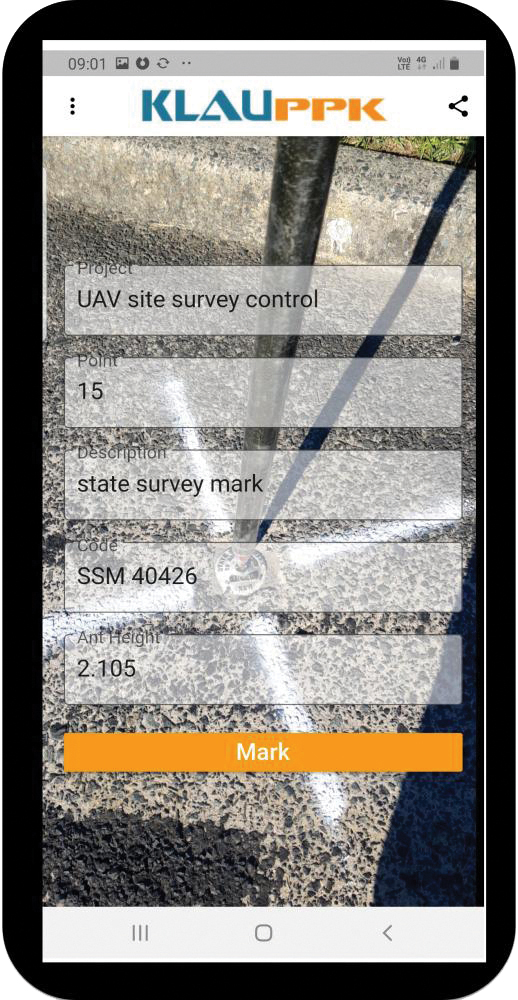
The KlauPPK Phone App, designed for use on drones with KlauPPK hardware and software, enables users to collect ground survey points with a name, description, feature code and antenna height like a traditional survey controller. The app sends the information to the operator’s computer for processing with the raw GNSS data logged in the KlauPPK unit on the pole. After post processing, the accurate survey data can be brought into CAD software to create points and line strings. The app takes a photo of the point being captured, and metadata is collected in the project. Users can place ground control points or check points, pick up as-built data like roads and utilities, and perform basic surveying. The system is compatible with the hybrid PPP/PPK MakeItAccurate post-processing service.
TerraLens 9.3 is a real-time software development toolkit for geospatial visualization. This release improves performance for 3D visualization for large viewports and multi-domain visualization features for command-and-control applications. It is significantly faster to enhance situational awareness. With increased multithreading in its map handling, TerraLens can load and display vector, raster and elevation formats smoothly without pre-processing, suitable for applications with disk size constraints or customers with a short turn-around time. A pre-processing option is still included. Improved data culling ensures only visible items will be rendered — especially noticeable when displaying large numbers of dynamic tracks and objects. New tools and features including support for OGC 3D Tiles for cityscapes, and a new API to control resolution of terrain mesh. Elevation warnings can now be displayed.
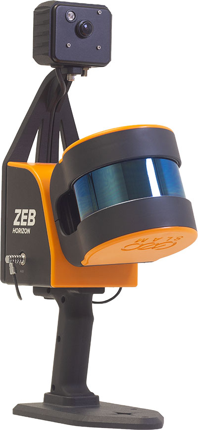
The ZEB Vision 16MP panoramic camera is now available for pre-order. Suitable for any ZEB Horizon, the new camera provides better colorization, image walkthroughs and point-cloud measurements using optional Draw software. Further updates mean GeoSLAM customers now can take a ZEB Horizon from handheld to UAV usage to get a more complete picture of projects. ZEB Horizon is compatible with the DJI Matrice 300 UAV.
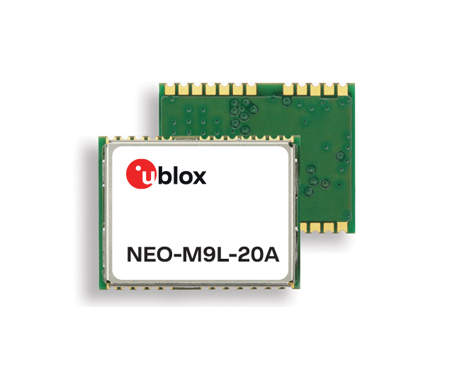
A new series of automotive-grade positioning modules are operational up to 105° C (221° F). The NEO-M9L modules and the M9140-KA-DR chip are built on the u-blox M9 GNSS platform and use dead-reckoning techniques to provide accurate position data when satellite signals are compromised or unavailable. The NEO-M9L-20A and NEO-M9L-01A modules, as well as the M9140-KA-DR chip, are specially designed for first-mount automotive solutions. The NEO-M9L-01A variant offers an extended operational temperature range up to 105° C, making it suitable for integration on the roof, behind the windscreen, or inside hot electronics control units. Applications include integrated navigation systems such as in-vehicle infotainment (IVI) and head units, integrated telematics control units and V2X.
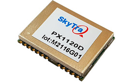
Provides positioning accuracy in tunnels, parking garages
Photo: SkyTraq
The PX1120D GNSS/inertial measurement unit (IMU) is suitable for both automotive pre-installation and aftermarket. The robust dead-reckoning module integrates a six-axis IMU and a concurrent quad-GNSS chipset. It receives signals from GPS, GLONASS, Galileo and BeiDou, as well as QZSS. The sensor-fusion module maximizes positioning accuracy in challenging environments, providing continuous navigation in tunnels and underground parking lots. For automotive pre-installation applications where vehicle wheel-tick signals are available, the PX1120D provides wheel-tick sensor fusion with automotive dead-reckoning. In aftermarket applications where wheel-tick signals are unavailable, the PX1120D provides an untethered dead-reckoning sensor-fusion solution. A single PX1120D module provides both automotive and untethered dead-reckoning functionality, simplifying logistics. It is suitable for infotainment systems, telematics control units, vehicle tracking, and advanced driver-assistance systems.
The Trooper Max 5G FR1 antenna platform is a 5G configurable and low-profile antenna platform for intelligent transportation and public safety applications. Configurable and optimized for multiband applications, the platform includes an option to add land mobile radio connectivity through an external whip port. With a slender shark-fin form factor, the Trooper Max is recommended for installation on public safety fleets. It is compatible with cellular routers supporting 600-MHz to 6-GHz frequencies. It also covers Wi-Fi 6 frequency ranges.
Version 7.9 of the CompassTrac fleet and asset management solution provides winter fleets with more detailed spreader controller information and greater insight through enhanced dashboard and reporting functions. Features include integration of numerous spreader controllers for granular, pre-wet and liquid materials; a snow-fighting dashboard consolidating key performance indicators; and a snow materials report that delivers historical reporting of granular, pre-wet and direct liquid material application rates and totals, including air and road temperature (where available). The fleet-management solution integrates GNSS, GIS and wireless networks, enabling end users to view the real-time locations and status of vehicles, people, and other high-value assets for full situational awareness.
New departure scheduling charts route, wind, tides
Photo: Savvy Navvy
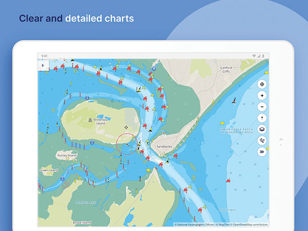
Smartphone app Savvy Navvy now allows boaters to plan better by visually showing the best time to depart given wind and tidal implications, leading to more informed and cost-saving decisions for journeys. By comparing passage times, as well as weather and tide information, boaters can immediately make crucial decisions based on safety, comfort, time and cost. Savvy Navvy is available on Android, iOS, PC and Mac and can be used on an unlimited number of devices simultaneously. It charts, weather, tide, marina details and passage planning with full tidal vectors. Active GPS tracking shows vessel position and enables boaters to instantly check course over ground (COG) and speed over ground (SOG). The app uses UKHO, NOAA and other official hydrographic charts from around the globe, as well as tide data from 8,000 tidal stations.
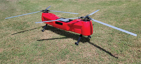
The Anzen EG-1250 provides a heavy lift, multi-drop, long endurance and flexible platform, expanding the services and operational support offerings from UAS Global Services. With an endurance of six hours, the EG-1250 can carry 75 pounds, cruise at 65 knots, in any weather day or night. The EG stands for an electric and gas dual-engine configuration, with the secondary engine able to power the aircraft or act as a power boost for the primary Skypower rotary SP-180 SRE engine. The Anzen EG-1250 is auto-rotation capable and offers an optional safety parachute system. The flexible platform can support industries such as maritime, agriculture, oil and gas, utility, cargo delivery and intelligence, surveillance and reconnaissance (ISR).
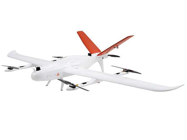
The P330 Pro is a high-performance vertical takeoff and landing (VTOL) fixed-wing UAS for aerial surveying and mapping. It provides high accuracy, long endurance and multiple payloads. It features a 100-Hz differential module, which allows aerial mapping operations at the centimeter level, and a flight endurance with payload reaching more than 150 minutes. The P330 Pro can be used to conduct small- and large-scale aerial surveys with extreme data quality, and is an alternative to manned aircraft for surveying and mapping, mining, construction and infrastructure, environmental monitoring and agriculture.
Capability expansion enables M300 for data capture
Photo: Skycatch
Flight1x software now provides data-capture capabilities for the DJI Matrice 300. The Skycatch High Precision Package provides mining operations with cloud or edge-based data processing that enables viewing terrain in 4D, automated RTK/PPK industrial drone management, and fast edge processing with data visibility in minutes. Built on technology adopted by large mining companies, Flight1x includes purpose-built flight automation software for the M300, leveraging DJI’s L1 and P1 sensors. Flight1x is part of the Skycatch High Precision Package, which provides mining operations with cloud or edge-based data processing that enables viewing terrain in 4D, automated RTK/PPK industrial drone management, and fast edge processing with data visibility in minutes.
Offers 5G and artificial intelligence capabilities
Photo: Qualcomm
The Flight RB5 5G platform is designed to accelerate development of commercial, enterprise and industrial drones. Powered by the Qualcomm QRB5165 processor, it condenses multiple complex technologies into a tightly integrated drone system. With 5G and Wi-Fi 6 connectivity, the platform enhances critical flying abilities beyond visual line-of-sight to support safer, more reliable flight. High-performance computing provides power efficiency for artificial intelligence and machine learning, enabling fully autonomous drones. A secure processing unit supports cybersecurity protections. New camera capabilities deliver premium image capabilities and performance. The Flight RB5 5G drone reference design is available through ModalAI. Use cases include mapping, inspection, film and entertainment, defense, security and emergency response, and delivery.
Spirent GNSS Foresight lets operators know where and when unmanned vehicles, air taxis and drones can operate safely and dependably beyond visual line of sight, especially in urban areas where buildings frequently obstruct GNSS signals. The cloud-based solution can produce forecasts using data from any of the world’s satellite constellations, and is of particular interest to the aviation, UAS and automotive industries. Spirent GNSS Foresight’s ability to accurately predict where and when autonomous systems will perform enables users to scale operations or services by expanding operational areas, reducing the number of system disengagements, and providing a greater level of safety and reliability assurance when reducing — or ultimately removing — human involvement in the driving or piloting task.
The General Lighthouse Authorities (GLA) of the United Kingdom and Ireland has named Alan Grant to the top post of its research and development team. Grant assumed his new role on Nov. 1.
As part of his duties, he heads the GLA’s research and development program, considering existing and future maritime requirements and operational strategy. GLA Research and Development (GRAD) is tasked with improving maritime safety by developing innovative and cost-effective maritime aids-to-navigation (AtoN).
GRAD projects have included all aspects of AtoN including human and machine interaction, operational life and environment. The team has deep technical expertise and experience with automatic identification systems (AIS) , the VHF Data Exchange System (VDES) , eLoran, e‑navigation, GNSS, SBAS and visual signaling.
The organization is well known for its expertise in electronic navigation aids and was an important contributor to the MarRINav project. The project effort was funded by the European Space Agency and examined what combination of electronic aids to navigation are needed to ensure uninterrupted UK shipping.
Grant joined the GLA in 2003 and has worked on a variety of systems during his time with GRAD. He led a series of successful GPS jamming trials and the development of the multi-system radionavigation receiver performance standards, from initial concept to international recognition at the IMO. He continues to support resilient positioning, navigation and timing in maritime navigation at both technical and strategic levels.
Grant is a Fellow of the Royal Institute of Navigation, where he is a member of the council and served as vice president, 2019-2021. He is also a member of the U.S. Institute of Navigation and served on the ION Council, 2013-2017.
Grant chairs the International Association of Marine Aids to Navigation and Lighthouse Authorities (IALA) radionavigation services working group and is a member of several international standards bodies. He is a chartered engineer, a chartered physicist, and author of more than 120 journal papers, magazine articles, and conference papers.
Martin Bransby, the prior GRAD leader, has taken a position with Telespazio in the UK.
Longstone Lighthouse is situated on the Outer Farne Islands on the Northumberland Coast in Northern England. (Photo: ad_foto/iStock/Getty Images Plus/Getty Images)
An Oculii sensor placed at the front corner of a vehicle. (Photo: Oculii)
Oculii’s patented adaptive AI software increases resolution of existing RF radar silicon up to 100X
Ambarella Inc. has entered into a definitive agreement to acquire Ohio-based Oculii Corp. Oculii’s adaptive artificial intelligence (AI) software algorithms are designed to enable radar perception using current production radar chips to achieve significantly higher (up to 100x) resolution, longer range and greater accuracy.
The fusion of Ambarella’s camera technology and Oculii’s radar software stack provides an all-weather, low-cost and scalable perception solution, enabling higher levels of autonomy for Tier 1 automakers and OEMs globally.
Oculii’s technology eliminates the need for specialized high-resolution radar chips, which have significantly higher power consumption and cost than conventional radar solutions. Oculii’s software can be deployed on Ambarella’s existing CVflow systems-on-chip (SoCs), operating in conjunction with radar RF solutions to increase safety and reliability.
The acquisition expands Ambarella’s addressable market into radar perception and fusion with its existing SoCs for automotive and other internet of things endpoint applications, including mobile robotics and security.
Oculii’s superior resolution and sensitivity can unlock the potential of everything from advanced driver-assistance systems (ADAS) and autonomous vehicles to robotics and security, by providing radar with a dynamic waveform that uses AI to learn from and adapt to the environment. The result is an extended operating range of up to 400 meters with a wide field of view.
To date, Oculii is engaged with 10 of the top 15 Tier 1s on software licensing, and has commercial development contracts with other OEM and AV companies. Oculii is generating pre-production revenue today, with production programs expected to commence in CY2023.
The boards of directors at both companies have approved the transaction, which is subject to customary closing conditions and expected to close during Ambarella’s Q4 FY2022 (ending January 31, 2022). Wilson Sonsini Goodrich & Rosati served as legal advisor to Ambarella, and Goodwin Procter served as legal advisor to Oculii. Greenhill & Co. served as financial advisor to Ambarella.
The Cowboy e-bike solution provides riders with high-performance, real-time GNSS accuracy, enabling them to map their own paths and those of the cities they live in.
The Cowboy e-bike uses smart road-companion applications to ensure riders get precise information, regardless of the route they travel. The positioning component uses Taoglas’ Accura GVLB258.A, a multi-band GNSS L1/L5, high-performance stacked patch antenna, in conjunction with u-blox’s SAM-M8Q GNSS positioning module. The combination allows for extremely low power and high accuracy.
The solutions works with “micromobility” services offered by Cowboy, such as Easy Rider for theft detection, bike insurance, and crash detection notifications.
Swift Navigation has been named Fleet Management Technology Company of the Year in the second annual AutoTech Breakthrough Awards conducted by AutoTech Breakthrough.
AutoTech Breakthrough is a market intelligence organization that recognizes the top companies, technologies and products in the global automotive and transportation technology markets.
Swift offers a highly-accurate, highly-reliable precise positioning solution that improves the operational efficiency of commercial transport, long-haul trucking and last-mile delivery, whether human-driven or autonomous. Swift’s fleet management precise positioning solution is comprised of the Skylark precise positioning service—delivering continent-wide, cloud-based corrections service — and the receiver-agnostic Starling positioning engine, which works with a variety of automotive-grade GNSS chipsets and inertial sensors, making centimeter-level GNSS accuracy a possibility without the cost of all new equipment.
Swift’s precise positioning solution delivers improved GNSS accuracy to make it easier to enable key fleet management capabilities such as lane-level analytics, route optimization and accurate traffic flow analytics to improve operational efficiency.
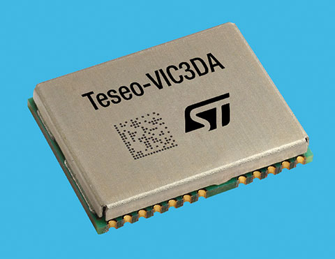
STMicroelectronics has introduced the Teseo-VIC3DA, the latest member of the Teseo module family, designed for vehicle positioning.
Teseo-VIC3DA combines ST’s high-performing Automotive Teseo III GNSS IC with the automotive 6-axis MEMS inertial measurement unit (IMU) and dead reckoning software to create a convenient, automotive-qualified navigation module. The module enables competitively priced in-car navigation, fleet-management, and insurance-monitoring applications.
The automotive Teseo III GNSS IC at the heart of the system is proven in high-end systems and is already highly regarded for its accuracy and efficiency. With multi-constellation awareness, Teseo III offers robust positioning capabilities by simultaneously receiving signals from GPS, Galileo, GLONASS, BeiDou and QZSS constellations.
The ST 6-axis automotive-grade MEMS IC introduces super-high-resolution motion tracking in advanced vehicle navigation and telematics applications.
With the combination of ST’s Teseo III, IMU and dead reckoning, the Teseo-VIC3DA ensures extremely accurate positioning performance in critical environments such as tunnels, beneath structures such as bridges or multi-level highways, in covered areas such as underground parking lots, and in urban canyons between tall buildings.
The Teseo-VIC3DA module operates from 3.3V, helping to simplify system integration, and has a standby mode that draws just 17 µA to minimize demand on the vehicle’s electrical supply. Containing a highly accurate integrated temperature compensated crystal oscillator, the module achieves excellent accuracy of 1.5 m circular error probability for typical automotive use cases. In addition, a dedicated real-time clock oscillator helps ensure fast time to first fix.
Coming with firmware pre-loaded onto built-in flash memory, the Teseo-VIC3DA can be updated with new firmware as necessary using the free Teseo-Suite software. Teseo-VIC3DA can provide up to 30Hz dead-reckoning fix-rate and has very low latency to reduce the UART-channel jitter. Teseo-VIC3DA can autonomously work with and without odometer information.
The Teseo-VIC3DA is tested and certified by ST according to the EU’s Radio Equipment Directive, applicable ETSI standards, and EN safety standards, helping customers achieve mandatory product-level approvals quickly and efficiently. A standalone, USB-powered evaluation platform, EVB-VIC3DA, is available to jump-start development.
The Teseo-VIC3DA is in production now and supplied in a 16 x 12.2 x 2.42 mm 24-pin LCC package.