By Nesreen I. Ziedan, Zagazig University, Egypt / Presented at ION GNSS+ 2017, September 2017
Above: The constructed 3D model for 26 buildings; below: illustration of the direction of recording of surfaces. (Images: Authors)
Multipath is a major source of positioning accuracy degradation in urban areas. Advances in 3D mapping and the availability of 3D city models have encouraged a set of new techniques for multipath mitigation.
This paper presents three algorithms to enhance the accuracy of urban positioning using all the available line-of-sight, multipath and non-line-of-sight signals:
An accelerated ray tracing technique that first eliminates the 3D surfaces that are invisible with respect to a position, and then analyzes the visible surfaces to predict the existence and path lengths of reflected signals. The ray tracing algorithm is applied on the possible range of positions.
A Markov Chain Monte Carlo-based algorithm that applies both the Gibbs sampler and the Metropolis-Hastings technique to analyze the received correlated signals to estimate the delays of reflected signals for all the received signals.
A Van Rossum-based technique that measures the discrepancy between the estimated delays and the predicted ones at a range of possible positions, where the position that generates the minimum discrepancy is taken as the estimated position. Test results indicate the ability of the algorithms to successfully utilize reflected signals to enhance urban positioning accuracy.
Velodyne Lidar Inc., maker of 3D vision systems for autonomous vehicles, is partnering with YellowScan to integrate its VLP-16 Puck and VLP-16 Puck LITE lidar sensors into YellowScan’s Surveyor.
The result is a turn-key and reliable lidar system for demanding UAV applications, the companies said.
Real-time lidar systems for UAVs are used around the world for industrial and scientific applications, including surveying, civil engineering, archeology and environmental science.
By combining its LiveStation app with the real-time 3D data capture capabilities of Velodyne’s VLP-16 Puck and VLP-16 Puck LITE sensors — both of which feature a 360-degree horizontal field-of-view, 100-meter range, and weigh 830 grams and 590 grams, respectively — YellowScan delivers a turn-key surveyor system that can be mounted to any drone for short-time data processing needs.
The result is a real-time in-flight lidar monitoring platform, with users able to see how the final map is being generated in real-time during the drone mission, and the basic map datasets available immediately after the mission.
“YellowScan is known for its commitment to providing reliable and easy to use sensing solutions for the UAV industry, which make the VLP-16 Puck sensors an easy choice for the Surveyor system,” said Erich Smidt, executive director, Europe, Velodyne Lidar. “The VLP-16 Pucks are some of our newest offerings, with significant effort put into reducing weight while maintaining the resolution and reliability expected of Velodyne’s industry-leading lidar sensors.”
“YellowScan Surveyor, the turn-key lidar solution integrating Velodyne’s advanced VLP-16 sensor, enables mapping professionals to do more in less time thanks to tremendously high density and accurate measurements acquired from UAVs,” said Tristan Allouis, CTO of YellowScan.
When it comes to renovating a building, unforeseen structural problems or lack of knowledge about the materials used can result in costly delays. Detailed site surveys help to highlight these issues before work begins — and digital technology is playing an increasingly important role in identifying them.
The GeoSLAM ZEB-REVO. (Image: GeoSLAM)
A project undertaken at a 112-year-old school highlights the advantages of using 3D mobile indoor mapping for rapid and simple site surveys.
“The beauty of scanning an historic building is that you find yourself delving into the stories behind its life,” said Stuart Cadge, sales and marketing coordinator at GeoSLAM. “As you peel back the layers you discover how the building has been used and altered over many decades of use.”
This was certainly the case at the Attucks school in Kansas City, Cadge said. The distinctive red-brick building was designed by local architect Charles A. Smith and built in 1905. It is known for its colonial revival influences and also played a key role in the educational history of the African-American community.
Two decades later, the school was suffering from over-crowding, and Smith was asked to extend it with a two-storey wing that connected to the east façade of the building. While the 1905 building had been symmetrical, the extension changed the floor plans considerably. Nevertheless, Smith delivered a sympathetic design that incorporated some of the original architectural details, ensuring the new wing was in keeping with the building’s aesthetic.
While details of the school’s building history are available on national and state registers, it would not have been possible to uncover problems in its structural condition without an accurate survey.
A Unique Challenge
Redeveloping and retrofitting a building like Attucks requires careful planning to uncover any existing conditions in its infrastructure. Civil engineering firm BHC RHODES was tasked with providing a 3D Revit building information model (BIM) of the building. The firm decided to use lidar 3D mobile mapping technology provided by GeoSLAM to achieve this.
The extremely rapid and efficient workflow of the GeoSLAM solution meant that possible setbacks in the project, caused by weakness in the structure, could be identified in advance, helping to speed up delivery time and reduce the overall project spend.
At Attucks, there were visible signs of deterioration to the wooden flooring, as well as concerns about ceiling collapses and air quality — specifically, asbestos.
The Value of Technology
“The process of mapping a historic building can expose site personnel to a number of risks, so BHC RHODES wanted to ensure they spent as little time on-site as possible,” Cadge explained.
As well as entering the Attucks building, personnel were required to move across the site safely, climb stairs and go into places that a trolley scanner could not.
On this basis, the firm chose the GeoSLAM ZEB-REVO, a handheld, lightweight, mobile mapping scanner, which employs 3D Simultaneous Localization And Mapping (SLAM) technology. In this case, it was seen as a much more time- and cost-effective alternative to terrestrial, static or trolley-based systems.
The complete 3D scan of the building comprises four separate scans and over 160 million data points. (Image: GeoSLAM)
“The ZEB-REVO is an incredibly useful tool for indoor mobile mapping, particularly in buildings with multiple storeys,” Cadge said. “It enables users to simply ‘walk and scan’ the building, in order to generate building footprints, 2D plans, area measurements for real estate and facility management, 3D BIM models — the list goes on.”
In the case of Attucks, just four-and-and-half hours were needed to scan the whole building, with the ZEB-REVO recording more than 43,000 measurement points per second. This was helped by the fact that operation of the device requires minimal staff training.
Results
Data from the ZEB-REVO and a trolley-based scanner were registered with Cyclone 9.1.4 to a common coordinate system before being exported to Autodesk ReCap as a .pts file format. From this, data was divided into 10-GB files to be used in ReCap and Revit 2014, where a level 200 BIM model was generated. The smooth and hassle-free workflow resulted in the entire building model being completed two weeks earlier than predicted.
The Jazz District Redevelopment Corporation (JDRC) in Kansas City has plans to transform Attucks into a new community performing arts facility, with office space, paying tribute to its African-American history. By supplying the JDRC with the geospatial data, the organization was better able to understand the structural condition of the building and consider how the space could be used.
The 3D point data was used to build a level 200 BIM model in Recap and Revit 2014. (Image: GeoSLAM)
The development will form an integral part of the 18th and Vine historic district in Kansas City, known as the Jazz District. The area is recognized as one of the cradles of jazz music in the 1920s and 1940s, and a historic hub of African-American businesses.
To secure approval on the plans for Attucks, JDRC must produce detailed drawings that show what materials will be used, as well as full dimension drawings, floor plans, site drawings and elevations. In addition, it must provide details, both graphically and in written form, on what parts of the building will remain and what renovation techniques will be used.
All this might present a number of challenges, but the scans produced by GeoSLAM’s ZEB-REVO show that the existing buildings are of exceptional quality. When the project does proceed, it will be able to do so quickly and efficiently thanks in part to the speed, simplicity and ease of use of the ZEB-REVO.
Blue Marble Geographics is offering a version 18.1 update to Global Mapper that includes numerous functional enhancements and introduces an new tools, upgrades to existing components, performance improvements and support for new formats and online data sources.
The release of version 18 of Global Mapper in September 2016 introduced a redesigned interface with significantly improved layer and workflow management as well as enhanced 3D display.
Building on this foundation, version 18.1 further improves the 3D experience with a new option to freeze the 3D View while working in the adjacent 2D view, speed improvements when rendering raster or 3D model formats, and improved functionality for creating 3D fly-though visualizations. For lidar module users, a new data quality-control tool is available for adjusting point cloud elevations to match surveyed ground control points.
Blue Marble’s GIS software is used by hundreds of thousands customers throughout the world who need affordable, user-friendly, powerful GIS solutions. Users are in industries including software, oil and gas, mining, civil engineering, surveying and technology companies, as well as government departments and academic institutions.
The release of version 18.1 offers numerous enhancements that are a testament to the ever-increasing importance of 3D data. Global Mapper’s 3D view, which introduced the ability to display an “infinite view” of all loaded 3D data in version 18, now offers the option to pause the 3D rendering when interacting with the 2D map. This streamlines workflow and significantly improves memory usage by eliminating the need to continually refresh the display.
The rendering speed for 3D raster layers as well as 3D models has also been drastically improved. When creating a 3D fly-through visualization or recording, the flight parameters now include bank angle, to more realistically simulate a pilot’s eye view, and variable velocity, allowing the flight speed to be adjusted between segments.
Other enhancements in version 18.1 include a new option to calculate a summary of the color statistics in a raster layer within a defined area; faster loading and display of large vector files such as shapefiles; support for many new formats, including exporting of LandXML and importing of RMaps/MBTiles and BPF lidar files; and expanded online data options including the General Bathymetric Chart of the Oceans (GEBCO).
Users of the optional Global Mapper Lidar Module, which provides advanced point cloud processing tools, can now perform precise quality control of their data against established ground control points. This allows the elevation values associated with each point to be adjusted to conform to the surveyed elevations at these locations.
“With more and more data having a height or elevation component, the importance of Global Mapper’s 3D viewing capability is underlined,” stated Blue Marble President Patrick Cunningham. “For several years, our development priority has been to optimize the user experience when interacting with lidar, DEMs or other 3D layers and with the release of version 18.1 we are seeing some of the results of that effort with more display control, improved 3D interaction, and stunning 3D visualization.”
Blue Marble application specialists will be conducting a live webinar on Tuesday, March 21, during which they will showcase the highlights of this release. This hour-long presentation is scheduled to begin at 2 p.m. (U.S. Eastern Time) and it will provide an opportunity to both see the latest tools and to ask questions about the new functionality. Space is limited and registration is required so be sure to sign up today.
For a complete list of new features and enhancements or to download a trial copy of Global Mapper 18.1, visit the website.
The Oregon Department of Transportation (ODOT) is embracing the growing trend in highway construction to go “stakeless” and push to full 3D design.
With more contractors using automated machine guidance applications, ODOT’s construction personnel are being asked to inspect projects with fewer stakes and visual indicators for line and grade. Employees are seeking to use the same data and information to determine line and grade when building or fixing stretches of road.
ODOT inspectors Jorge Jimenez and Mike Stennett at Multnomah Falls, preparing for a night-time paving operation. (Photo: Chris Pucci)
To address this need, rugged tablet maker DT Research worked closely with ODOT to design purpose-built Inspector Positioning Tablets that run GPS locating and 3D modeling applications, and take advantage of the Oregon Real-Time GNSS Network.
“MicroSurvey Field Genius surveying software is used to read XML files directly, allowing the inspector to work with the same files that the contractors received from the roadway designers,” said Chris Pucci, ODOT Construction Automation Surveyor.
The tablets enable ODOT to fully use its knowledge of the Oregon Real-Time GNSS Network and expertise in survey-grade RTK GNSS to achieve accuracies of +/0.05 feet.
The model DT391GS tablets have 9-inch touchscreens. The tablets can be used as handhelds or with an external antenna and pole. ODOT purchased one of four GNSS options offered by DT Research for the DT391GS tablets. The options enable inspectors and construction crews to employ a combination of GPS locating and 3D modeling to guide construction workers.
The goal is to allow the inspectors to make the same checks they would have made if there had been traditional construction staking on a project, not to make inspectors into surveyors, Pucci noted.
A one-day training is provided to train construction personnel before they are issued a tablet. “The tablets have been very well received by our construction inspection personnel,” he said.
The tablet project is now in the pilot phase with 20 tablets deployed to eight construction offices and more than 70 construction personnel having been trained. “We also just placed an order for 22 more tablets for the upcoming 2017 construction season,” Pucci said.
Size, weight and power designed for smaller unmanned platforms
MB-Two module by Trimble.
The MB-Two GNSS module delivers highly accurate GNSS-based heading plus pitch or roll in an advanced industry standard form-factor for system integrators. The module’s embedded Z-Blade GNSS technology uses all available dual-frequency GNSS signals equally, without any constellation preference, to deliver fast and stable centimeter-accurate position and heading information. The MB-Two is designed for a wide variety of applications such as unmanned, agriculture, automotive, marine and military systems. The MB-Two features an enhanced dual-core GNSS engine with 240 channels capable of tracking L1/L2 frequencies from the GPS, GLONASS, Galileo and BeiDou constellations. The GNSS engine supports Trimble RTX correction services, including CenterPoint RTX and RangePoint RTX, delivered worldwide via L-Band satellite. The MB-Two combined with CenterPoint RTX delivers centimeter-level positioning without requiring a local base station or VRS network.
High performance, uninterrupted positioning for vehicle applications
The S1722DR8 GNSS dead-reckoning receiver, compared to a U.S. penny.
The S1722DR8 GNSS dead-reckoning receiver integrates a three-axis gyroscope/accelerometer and barometric pressure sensor with a GNSS receiver. Using wheel speed data from a vehicle, the S1722DR8 achieves 100-percent coverage. It can be flexibly mounted in any orientation, and does not have to be placed horizontally as do conventional dead-reckoning solutions that use a single-axis gyroscope. Its auto-calibration feature simplifies installation, while the short calibration time upon first use improves the user experience. The barometric pressure sensor provides highly accurate altitude information, which is useful for differentiating floor levels of multi-story parking garages or stacked highways.The S1722DR8 measures 17 x 22 millimeters. It offers continuous navigation even in GPS-signal-denied environments such as tunnels or underground parking lots.
The HX-DU1603D rover radio is an advanced, high-speed, Bluetooth-enabled wireless data link designed for GNSS/RTK (real-time kinematic) surveying and precise positioning. It is a lightweight, ruggedized UHF receiver for digital radio communications between 410 and 470 MHz in either 12.5- kHz or 25-kHz channels, which can be widely used in GNSS/RTK surveying and GNSS precise positioning systems. The HX-DU1603D is equipped with a Bluetooth transceiver for cable-free communications with external devices. It features an internal, rechargeable battery for ease of use and portability that allows long operational hours. Its display screen and buttons can be used to configuration parameters such as frequency, protocols, power display, serial port baud rate and air baud rate. By deploying the technology, users can instantly communicate with GNSS precise positioning receivers that share the same protocols throughout the world. The rover radio HX-DU1603D joins the line of Harxon products that include 25W base radio HX-DU8602T with simplex and 35W base radio HX-DU8608D with Duplex.
EyesMap3D generates accurate 3D models and point clouds, measured directly from images. It allows users to create high-density points clouds with textures achieving a realistic 3D model appearance. It is able to measure accurately on the images to generate true orthophotos, and geo-reference and scale the results. eyesMap3D users can use their cameras, mobile phone or camera drone to capture images. The program is compatible with most popular software packages on the market. The goal of maker eCapture is to allow the user to easily generate and work with 3D models and photogrammetric tools, while maintaining data quality.
Scope of Project: The 3D mapping project encompasses all of Singapore — more than 700 square kilometers.
The Singapore Land Authority (SLA) is engaged in a 3D mapping initiative to create and maintain a high-resolution survey-accurate 3D national map. Denmark and Switzerland have national 3D maps, and Hong Kong has mapped its central business district.
3D virtual environments support city planning, decision-making and risk management. SLA’s project involves capturing vast amounts of data and creating 2D and 3D datasets in several formats. The project began in April 2014 with airborne data capture and modeling; the modeling of buildings is expected to be completed this month. Mobile data capturing and road modeling is expected to be completed by the end of 2016.
The 3D models of buildings and road infrastructure are being created from high-quality images and laser-scanning data. The 3D data is stored in the open information model CityGML, which allows for 3D spatial analysis, simulation and visualization.
The project has employed multiple rapid mapping technologies such as oblique imagery, airborne laser scanning, mobile laser scanning and terrestrial scanning, resulting in more than 500 terabytes of data in multiple formats.
Using Bentley Map software, the project team created, maintained and disseminated 3D information directly from the Oracle Spatial database platflorm. In November, Bentley Systems awarded the 3D mapping project the 2015 Be Inspired Award for Innovation in Government.
Building Level of Detail 2: The Singapore project will model up to LOD2.The five levels of detail (LOD) in CityGML are LoD0 (terrain model), LoD1 (block models with no roof structures), LoD2 (explicit roof structures), LoD3 (detailed architectural models) and LoD4 (interior modeling).
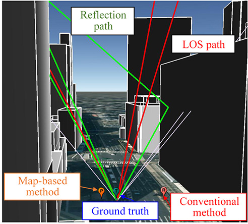
Figure 1. Example of the GNSS signal propagation using ray-tracing and a 3D building map.
A particle-filter-based positioning method using a 3D map to rectify the errors created by multipath and non-line-of-sight signals on the positioning result delivered by a low-cost single-frequency GPS receiver takes a multi-GNSS approach, using the combined signals of GPS, GLONASS and QZSS. The method outperforms conventional positioning in availability and positioning accuracy. It will likely be fused with other sensors in a future pedestrian navigation application.
By Li-Ta Hsu, Shunsuke Miura and Shunsuke Kamijo
GPS provides an accurate and reliable positioning/timing service for pedestrian application in open field environments. Unfortunately, its positioning performance in urban areas still has a lot of room for improvement, due to signal blockages and reflections caused by tall buildings. The signal reflections can be divided into multipath and non-line-of-sight (NLOS) effects. Recently, use of 3D building models as aiding information to mitigate or exclude multipath and NLOS effects has become a promising area of study.
At first, researchers used the 3D map model to simulate multipath effects to assess the single-reflection environment of a city. Subsequently, the metric of NLOS signal exclusion using an elevation-enhanced map, extracted from a 3D map, was developed and tested using real vehicular data. An extended idea of identifying NLOS signals using an infrared camera onboard a vehicle has been suggested. The potential of using a dynamic 3D map to design a multipath-exclusion filter for a vehicle-based tightly coupled GPS/INS integration system has also been studied. A forecast satellite visibility based on a 3D urban model to exclude NLOS signals in urban areas was developed.
The research approaches outlined above seek to exclude the NLOS signal; however, the exclusion is very likely to cause a horizontal dilution of precision distortion scenario, due to the blockage of buildings along the two sides of streets. In other words, the lateral (cross direction) positioning error would be much larger than that of the along-track direction.
Therefore, approaches applying multipath and NLOS signals as measurements become essential. One of the most common methods, the shadow-matching method, uses 3D building models to predict satellite visibility and compare it with measured satellite visibility to improve the cross street positioning accuracy. A multipath and NLOS delay estimation based on software-defined radio and a 3D surface model based on a particle filter was proposed and tested in a static experiment in the Shinjuku area of Tokyo.The research team of The University of Tokyo developed a particle-filter-based positioning method using a 3D map to rectify the positioning result of commercial GPS single-frequency receiver for pedestrian applications.
An evaluation of the QZSS L1-submeter-class augmentation with integrity function (L1-SAIF) correction to the proposed pedestrian positioning method was also discussed in an earlier paper by the authors of this article. However, satellite visibility in the urban canyon using only GPS and QZSS would not be enough for this proposed method. The use of emerging multi-GNSS, encompassing GLONASS, Galileo and BeiDou, could furnish a potential solution to the lack of visible satellites for this method. This article assess the performance of the proposed pedestrian positioning method using GPS, GLONASS and QZSS.
Building Models Construction
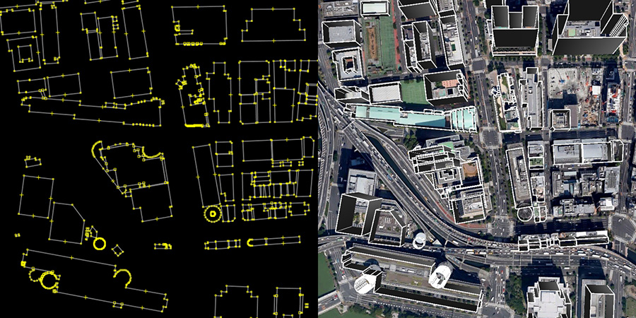
Our work established a 3D building model by a 2D map that contained building location and height information of buildings from 3D point-clouds data. The Fundamental Geospatial Data (FGD) of Japan, which provided by Japan geospatial information authority, is open to the Japanese public. This FGD data is employed as 2D geographic information system (GIS) data. Thus, the layouts and positions of every building on the map could be obtained from the 2D GIS data. In this article, the 3D digital surface model (DSM) data is provided by Aero Asahi Corporation. Figure 2 shows the process of constructing the 3D building model used here. This process first extracts the coordinates of every building corner from FGD as shown in the left of Figure 2. Then, the 2D map is integrated with the height data from DSM. The right of Figure 2 illustrates an example of a 3D building model established in this way. The 3D building map contains a very small amount of data for each building in comparison to that of the 3D graphic application. For our purposes, the file only contains the frame data of each building instead of the detail polygons data. This basic 3D building map is utilized in the simulation of ray-tracing.
Figure 2. The construction of the 3D building map from a 2D map and DSM.
Our version of the ray-tracing method does not consider diffractions or multiple reflections because these signals occurred under unfavorable conditions. Here, we utilize only the direct path and a single reflected path. The developed ray-tracing simulation can be used to distinguish reflected rays and to estimate the reflection delay distance. Our research work assumes that the surfaces of buildings are reflective smooth planes, that is, mirrors. Therefore, the rays in the simulation obey the laws of reflection. In the real world, the roughness and the absorption of the reflective surface might create a mismatch between the ray-tracing simulation and the real propagation. Here we ignore this effect, as the roughness of the building surface is much smaller than the propagation distance.
The opening figure (Figure 1) shows an example of the GNSS signal propagation using ray-tracing and a 3D building map. Red, green and white lines denote the LOS path, reflected paths and the NLOS paths, respectively. In this environment, a conventional positioning method such as weighted least squares (WLS) usually estimates the position on the wrong side of street as shown in the red balloon. With the aid of 3D building model and ray-tracing, the map-based positioning method is able to provide a result close to the ground truth.
Map-Based Pedestrian Positioning
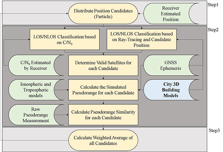
The flowchart of the 3D city building model-based particle filter is shown in Figure 3. This method first implements a particle filter to distribute position candidates (particles) around the ground-truth position. In Step 2, when a candidate position is given, the method can evaluate whether each satellite is in LOS, multipath or NLOS by applying the ray-tracing procedure with a 3D building model. According to the signal strength, namely carrier-to-noise ratio (C/N0), the satellite could be roughly classified into LOS, NLOS and multipath scenarios. If the type of signal is consistent between C/N0 and ray-tracing classification, the simulated pseudorange of the satellite for the candidate will be calculated. In the LOS case, simulated pseudoranges can be estimated as the distance of the direct path between the satellite and the assumed position. In the multipath and NLOS cases, simulated pseudoranges can be estimated as the distance of the reflected path between the satellite and the candidate position via the building surface.
Figure 3. Flowchart of the particle filter using 3D city building models.
Ideally, if the position of a candidate is located at the true position, the difference between the simulated and measured pseudoranges should be zero. In other words, the simulated and measured pseudoranges should be identical. Therefore, the likelihood of each valid candidate is evaluated based on the pseudorange difference between the pseudorange measurement and simulated pseudorange of the candidate, which is simulated by 3D building models and ray-tracing.
Finally, the expectation of all the candidates is the rectified positioning of the proposed map method. This method can therefore find the optimum position through a dedicated optimization algorithm of these assumptions and evaluations. The positioning principle of the proposed method is very different from the conventional GPS positioning method, that is, WLS. As a result, the calculation of the positioning accuracy of the 3D map method should be also different.
We define two positioning performance measures for the 3D map method: user range accuracy of the 3D map method (URA3Dmap) and positioning accuracy.
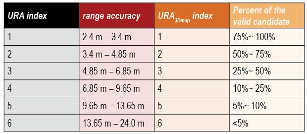
The value of URA3Dmap is to indicate its level of positioning service, which is similar to the user range accuracy (URA) of conventional GPS. The URA3Dmap is defined based on the percentage of the valid candidates from all candidates outside the building. The higher percentage of the valid candidate implies a higher confidence of the estimated position. Ideally, if the center of the candidate distribution is not far from the ground truth, the simulated pseudorange of the candidates located at the center of distribution would be very similar to the measurement pseudorange. We define the URA3Dmap as shown in Table 1.
Table 1. The definition of URA and URA3Dmap used in this article.
Experiments and Discussion
We selected the Hitotsubashi and Shinjuku areas in Tokyo to construct a 3D building model because of the density of the tall buildings. In this area, multipath and NLOS effect are frequently observed. We tested pedestrian navigation in a typical path that included walking both sides of street and passing through/waiting at a road intersection. The cut-off angle is 20 degrees. The data were collected in November and December 2014.
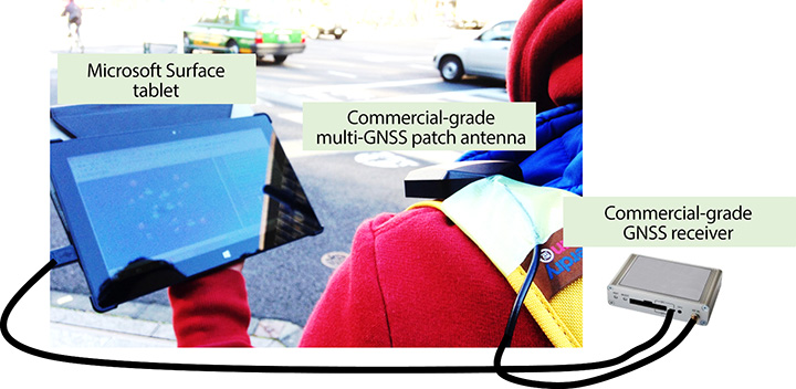
We compare here two single point positioning methods: single-point positioning solutions provided by open source RTKLIB software (RTKLIB SPP), and the proposed 3D map method. RAIM FDE of the RTKLIB SPP is used here as a conventional NLOS detection algorithm. The test used a geodetic-grade GNSS receiver and a commercial grade receiver. The geodetic receiver was only used to collect the QZSS L1-SAIF correction signal. The antenna of the commercial receiver was attached in the strap of the backpack as shown in Figure 4. The receiver is connected to a tablet to record the GNSS measurements and is set to output pseudorange measurements and positioning results every second.
Figure 4. Equipment set-up.
We generated a quasi-ground truth using a topographical method.Video cameras were set in the ninth and18th floors of a building near the Hitotsubashi and Shinjuku areas, respectively, to record the traveled path. The video data output by the cameras are used in combination with one purchased high-resolution aerial photo to get the ground truth data. The aerial photo is 25 cm/pixel and therefore the error distance for each estimate can be calculated. The synchronization between video camera and commercial GNSS receiver is difficult to get as accurate as in the topographical method. As a result, we used point to “points” positioning error to evaluate the performance of the dynamic experiment. The synchronization error is limited to 1 second. Hence, for each estimated position x(t), the ground truth points used to calculate the positioning error is xGT (t-1), xGT (t) and xGT (t+1). The point to “points” positioning error is calculated as:
Three performance metrics are used here: mean, standard deviation of the point to points error, and the availability of positioning solution. The availability defined here means the percentage of given solutions in a fixed period. For example, if a method outputs 80 epochs in 100 seconds, the availability of the method is 80 percent.
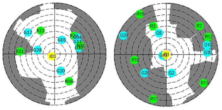
This research demonstrates two dynamic data. The skyplot of the data are shown in Figure 5. The satellites are tracked by the commercial receiver. The grey areas indicate the obstruction of the surrounding buildings. The two dynamic data are typical signal receptions at Hitotsubashi (middle urban canyon) and Shinjuku (deep urban canyon) areas.
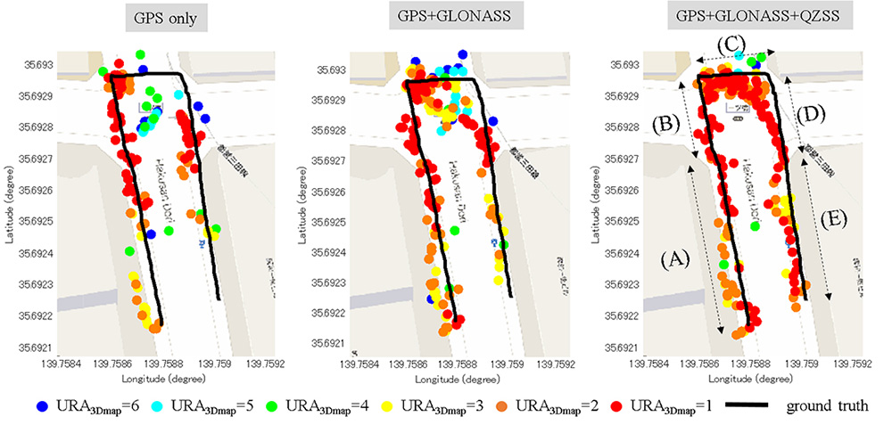
Hitotsubashi Mid-Canyon. To study the benefit of using different GNSS constellations in the 3D map method, Figure 6 shows the trajectory estimated by the proposed method under different satellite constellations. The different colors indicate different values of URA3Dmap of each point. This walking trajectory is divided into five sections (identified as A, B, C, D and E in the right-most of the three plots). In the GPS-only case (left), results in A and B sections have much better performance than sections D and E, because more than half of the GPS satellites are blocked at D and E, as shown in the left of Figure 5.
Figure 5. The left and right are the skyplot of the dynamic experiment at the Hitotsubashi and Shinjuku areas, respectively, in Tokyo.
The middle plot in Figure 6 shows the trajectory using GLONASS. It is obvious that the positioning results located at the right side of street are greatly increased, derived from the greater number of satellites in view. However, the quality of the GLONASS signal is not as good as GPS because multipath has a double effect on GLONASS.
Figure 6. Positioning results of the proposed 3D map method using different combinations of satellite constellations in a middle urban canyon.
In summary, the positioning error of applying GLONASS maintains a similar level, and availability increases about 12 percent compared to using GPS only. The right plot of Figure 6 shows the result after adding QZSS L1 C/A and L1-SAIF. This increases the results of C, D and E sections, because QZSS provides a high-elevation-angle satellite to the 3D map method. As a result, the number of valid candidate points in C, D and E sections increases dramatically. The reliability in C, D and E sections is also much higher than that of GPS+GLONASS. In addition, the trajectory became smoother than before.
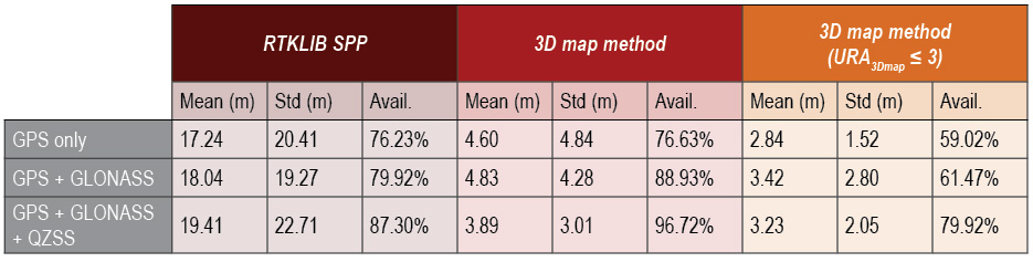
Table 2 compares the positioning results of both RTKLIB SPP and the 3D map method, showing the 3D map method using GPS, GLONASS and QZSS to have the best performance among three scenarios. The positioning error mean and availability are 3.89 meters and 96.72 percent, respectively. The positioning error mean could be further improved to 3.23 meters if selecting the position point with URA3Dmap ≤ 3 (yellow, orange and red points in Figure 6). This selection will lose about 17 percent of availability.
Table 2. Positioning results of the 3D map method using different combinations of satellite constellations in a middle urban canyon.
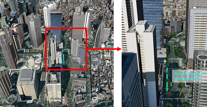
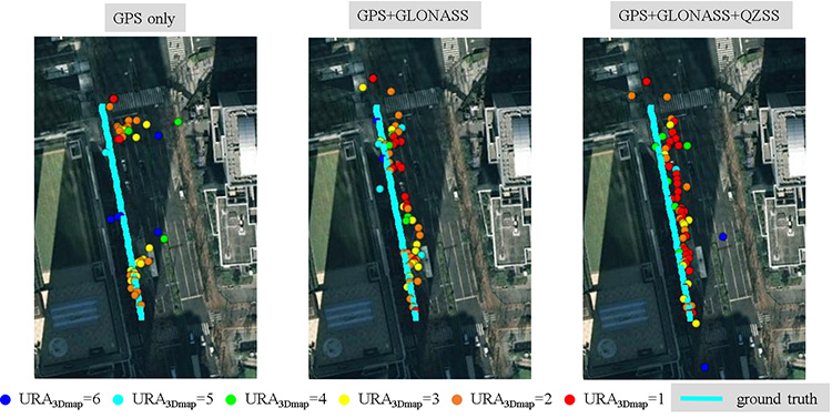
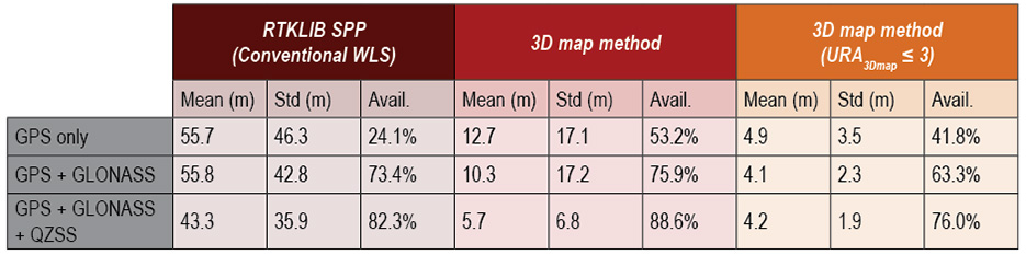
Shinjuku Deep Canyon. We conducted a similar experiment in the Shinjuku area of Tokyo, the most urbanized area in Japan (Figure 7). The positioning results and skyplot are shown in Figure 8 and the right of Figure 5, respectively. Table 3 compares the results of the two methods using the three constellation configurations.
Figure 7. Deep urban canyon environment, Shinjuku, Tokyo. (Courtesy Google Earth)Figure 8. Positioning results of the proposed 3D map method using different combinations of satellite constellations in a deep urban canyon.Table 3. Performance comparison of RTKLIB SPP and the proposed 3D map method using different combinations of satellite constellations in a deep urban canyon.
As shown in the left of Figure 8, only half of the GPS-only solutions are on the correct side of the street. A few points are incorrect due to the insufficient number of satellites. Adding GLONASS measurements greatly increases the availability, and most of the GPS-only outliers are corrected. The positioning error mean improves from 12.7 to 10.3 meters, and the availability improves from 53.2 to 75.9 percent. GLONASS measurements provide such a significant improvement because the distribution of GPS and GLONASS satellites are complementary.
After adding the QZSS measurements, availability further increases to 88.6 percent, and positioning error mean is reduced to 5.7 meters. The positioning error mean could be further improved to 4.2 meters if selecting the position points with URA3Dmap ≤ 3: the red, orange and yellow points in Figure 8. Although this selection will lose about 12 percent of availability, it could be easily compensated by a simple filtering technique.
Comparing Table 2 and Table 3, we find the positioning error of the proposed method in the middle urban canyon is about 1 meter worse than that in the deep urban canyon. This is because of the increase of multiple reflected signals.
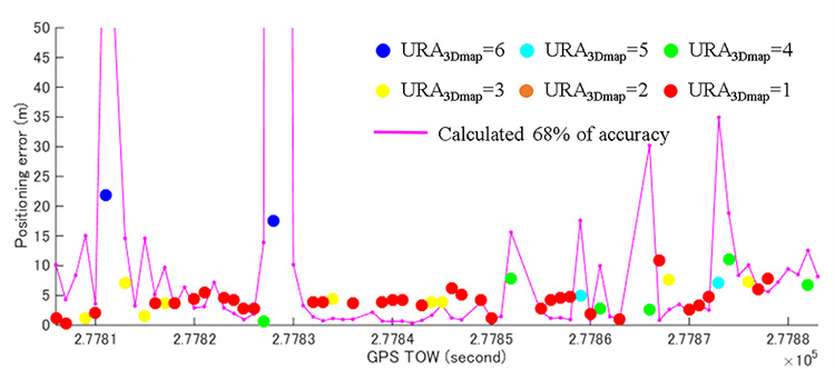
The target application of this 3D map method is consumer-based pedestrian navigation. Most of these applications benefit from an integrated system of multiple sensors. The 3D map method could serve as one sensor for such an integrated system. The calculation of positioning accuracy is required to indicate the quality of the point solution estimated by this method. Figure 9 shows the relationship between the calculated accuracy and positioning error. We can find that the calculated accuracy is able to describe the performance of the proposed method.
Figure 9. Positioning error of the 3D map method using GPS+GLONASS+QZSS. The purple line denotes the calculated 68 percent accuracy of the proposed method.
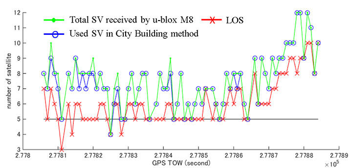
The performance of the conventional method is very inaccurate in this deep urban canyon. Its positioning error is larger than 40 meters. Figure 10 shows the number of satellites in this data. Note the number of LOS satellites is determined by the ray-tracing simulation according to the ground truth trajectory.
Figure 10. Number of LOS satellites, the number of satellites used in the 3D map method, and the total number of satellites tracked by the commercial-grade receiver.
The number of LOS satellites means the light-of-sight path of satellite is not blocked by buildings. Note that the LOS signal also contains the multipath effect. In this deep urban canyon, the number of LOS signals is much less than that of all received satellites. This implies a lot of NLOS is received, which deteriorates the performance of the conventional method. The map-based method is able to correct most of the NLOS signals.
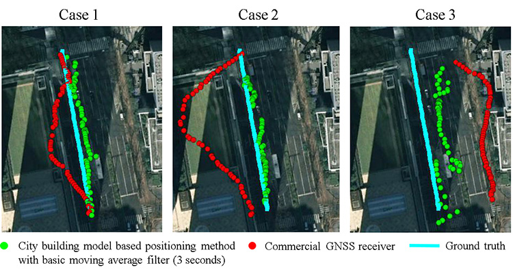
The number of satellites used in the map-based method is close to the number of all the satellites received. Therefore the map-based method can achieve better performance than the conventional method. Figure 11 demonstrates the comparison between the map-based method and the commercial GNSS receiver. The map-based method is simply smoothed by a moving average filter with 3 seconds data. It is difficult to understand the pedestrian trajectory by the commercial-grade receiver result. In some cases, the commercial receiver will estimate the pedestrian to be on the wrong side of the streets. The proposed method, instead, is capable of estimating the result at the correct side of the street.
Figure 11. Positioning results of the proposed 3D map method and commercial-grade receiver using GPS+GLONASS+QZSS in the deep urban canyon.
Li-Ta Hsu is a post-doctoral researcher at the Institute of Industrial Science of the University of Tokyo. He received his Ph.D. degree in aeronautics and astronautics from National Cheng Kung University, Taiwan.
Shunsuke Miura received an M.S. degree in information science from the University of Tokyo in 2013.
Shunsuke Kamijo received a Ph.D. in information engineering from the University of Tokyo, where he is now an associate professor.
This map depicts the proposed body of work for 3DEP in Fiscal Year 2015. The BAA awards will add more than 95,000 square miles of 3DEP quality LiDAR data to the national database.
The U.S. Geological Survey National Geospatial Program is developing the 3D Elevation Program (3DEP) to respond to growing needs for high-quality topographic data and for a wide range of other three-dimensional representations of the nation’s natural and constructed features.
To expand awareness of 3DEP status and plans, as well as provide an open forum for 3DEP stakeholders to communicate and coordinate potential Broad Agency Announcement (BAA) proposals, the USGS is offering numerous state and regional coordination workshops.
The primary goal of 3DEP is to systematically collect 3D elevation data in the form of light detection and ranging (LiDAR) data over the conterminous United States, Hawaii, and the U.S. territories, with data acquired over an eight-year period. Interferometric synthetic aperture radar (ifsar) data will be acquired for Alaska, where cloud cover and remote locations preclude the use of LiDAR in much of the state.
The 3DEP initiative is based on the results of the National Enhanced Elevation Assessment that documented more than 600 business uses across 34 federal agencies, all 50 states, selected local government and tribal offices, and private and nonprofit organizations. A fully funded and implemented 3DEP would provide more than $690 million annually in new benefits to government entities, the private sector and citizens.
3DEP is a “Call for Action” because no one entity can accomplish it independently. 3DEP presents an opportunity for collaboration between all levels of government to leverage the services and expertise of private-sector mapping firms that acquire the data, and to create jobs.
“When partners work together, they can achieve efficiencies and lower costs so that 3DEP can become a reality,” the USGS said in a press release. “When 3D elevation data are available to everyone, new innovations will occur in forest resource management, alternative energy, agriculture, and other industries for years to come,” the USGS said.
Esri has released ArcGIS 10.3.1, bringing new capabilities.
Smart Mapping is an innovative approach for creating maps that is available through ArcGIS Online. Users can quickly style the features of a map to create useful and visually stunning maps every time, Esri said.
3D Web Scenes allow users to view, create, and share 3D web scenes in a browser. Available in ArcGIS for Server and Portal for ArcGIS, users can share these scenes within their own infrastructure or make them public.
With the ArcGIS 10.3.1 release, ArcGIS for Server with Portal for ArcGIS can now host web scenes and layers that include multipatch–based 3D models and symbology, such as photo-realistic buildings, trees, and visibility domes.
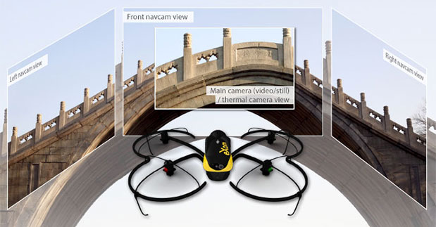
Swiss professional drone maker senseFly has launched the eXom, its new quadcopter UAS for mapping and inspection. The eXom is available to pre-order immediately and ships this summer.
The eXom is a sensor-rich system, sensefly said. Developed by experts working across numerous fields of robotics, this lightweight quadcopter offers professionals such as civil engineers and land surveyors the situational awareness, imaging flexibility and durability they need to complete challenging tasks safely, accurately and efficiently.
“We believe the eXom’s level of application-focused technology is unique in the civilian drone market,” said Antoine Beyeler, CTO and co-founder of senseFly. “This platform tightly integrates several one-of-a-kind features, such as TripleView imaging, advanced situational awareness and full flight mode flexibility — to provide inspection and mapping professionals with the functionality they desire from a rotary system.”
eXom is a future-ready platform with a quad-core computer onboard, senseFly said. Like senseFly’s fixed-wing drones, it offers users evolving performance through regular software updates, adding the latest drone tech innovations to keep the eXom at the cutting edge for years to come, the company said.
eXom’s low take-off weight of 1.7 kg (3.7 lb) ensures its users will, in many countries, have less flight authorization paperwork to deal with than those who use heavier systems.
The eXom’s advanced integrated sensors work together to provide the user with full situational awareness and support obstacle avoidance:
Five navcam vision sensors allow the operator to see in the direction the drone is moving, automatically via its flight control software, without needing to turn the system’s TripleView camera head. This technology is similar to the visual parking sensors in modern cars, but brought into a 3D flight environment.
Five ultrasonic proximity sensors work in harmony with eXom’s navcams to ensure the operator always knows the drone’s distance from nearby objects. (The drone’s shock-absorbent carbon fibre shrouding is also always on hand to protect its rotors in case of surface contact.)
Numerous other sensors, including inertial measurement units, barometers, magnetometers, GPS and magnetic encoders, maximize the drone’s stability and safety.
eXom’s autopilot-controlled TripleView camera head enables the user to view and record three different types of imagery during a single flight without needing to land to change cameras:
HD video
Ultra high-resolution stills
Thermal still/video
Because the TripleView head faces forwards, eXom can fly up close to target structures such as building walls and dams to achieve sub-millimeter data resolutions. Plus, with the head’s 270-degree vertical field of view, users can document objects positioned directly above and below the drone — crucial for tasks such as bridge and roof inspections.
eXom offers various flight modes:
Autonomous mode — for mapping projects. First, create a flight plan using eMotion X’s mission blocks. eXom then launches, flies, acquires geo-referenced imagery and lands itself.
Interactive ScreenFly mode — this streaming video mode is for live inspection tasks. Use the supplied joypad to navigate and orient the drone via computer screen. This mode includes flight assistance features such as cruise control and distance lock.
Create a flight plan, launch in autonomous mode, then go live on demand.
No matter which mode is activated, RC-based manual control always remains available as a backup function and for experienced pilots.
Visit senseFly at Unmanned Systems 2015: Hall B2, Booth 519. The eXom will be demonstrated in flight at the senseFly booth at at the show’s Air & Ground Demo Area (demo timings: May 6, 12:15 and 14:15, May 7, 11:45 and 14:15).
Topcon Positioning Group has announced the latest edition of its 3D mobile mapping system. The IP-S3 is on display at the SPAR International 3D Measurement and Imaging Conference, held March 30-April 2 in Houston, Texas. The system employs the integration of an inertial measurement unit (IMU) and GNSS receiver with a vehicle’s onboard electronics to offer high-density mobile digital imaging.
“The IP-S3 is more compact, lightweight, and scans at a rate of up to five times faster than previous models,” said Charles Rihner, vice president of the Topcon GeoPositioning Group. “Weighing in at 39 lbs. (18 kg), it’s light enough that a single person could mount it on a car, truck or SUV without any assistance from anyone else.”
Scanning at 700,000 points-per-second, the rotating LiDAR sensor captures the 360-degree environment with 32 internal lasers. The IP-S3’s six-lens digital camera is designed to provide data-rich results with its 30 MP panoramic imagery.
The system pairs with Topcon Mobile Master Field and Office software suite to perform all post-processing functions in a single application.
“The software suite offers a complete all-in-one processing workflow, turning raw sensor data collected by the IP-S3 system into rich and precise point clouds and images,” Rihner said.