Not just supporting players, alternative positioning, navigation and timing (PNT) systems strengthen, augment and — when needed — replace GNSS. We explore how companies are using alternative PNT, and talk with John Fischer of Orolia and Alexis Guinamard of SBG Systems about their companies’ latest developments.
Since the 1990s, GPS has provided the United States military with a substantial tactical edge. Civilian GPS applications are now deeply embedded in every aspect of our lives. The U.S. Department of Transportation recently reaffirmed that GPS’ positioning, navigation, and timing (PNT) services are critical to the safe and efficient use of the national transportation system, and a Feb. 12 presidential executive order declared that satellite-based PNT services “have become a largely invisible utility for technology and infrastructure.”
It has long been equally well known, however, that GPS is vulnerable to accidental and intentional interference (the latter known as jamming), spoofing, and degradation or denial of signals. Additionally, GPS satellites are increasingly vulnerable to damage or destruction by space debris or intentional attack. The executive order mentioned above declared it U.S. policy “to ensure that disruption or manipulation of PNT services does not undermine the reliable and efficient functioning of [the country’s] critical infrastructure.”
Protecting PNT requires not just strengthening GPS, but also developing alternative sources of PNT data and ways to integrate them into the myriad systems that currently rely on GPS.
The National Timing Resilience and Security Act of 2018 (passed by the U.S. Senate as part of that year’s Coast Guard authorization act), called for “a complement to and backup for” the GPS timing component “to ensure the availability of uncorrupted and non-degraded timing signals for military and civilian users in the event that GPS timing signals are corrupted, degraded, unreliable or otherwise unavailable.” It mandated the procurement of a wireless, terrestrial system that would provide wide-area coverage and be synchronized with UTC, resilient and extremely difficult to disrupt or degrade, able to penetrate underground and inside buildings, and capable of deployment to remote locations.
A report released on April 8 by the Department of Homeland Security (DHS), however, recommends “that responsibility for mitigating temporary GPS outages be the responsibility of the individual user and not the responsibility of the federal government.” It points out that research by one of DHS’ agencies “shows that users can mitigate short-term GPS disruptions (e.g., inability to read a GPS signal) with various strategies, ranging from using local backup capabilities to delaying operations until GPS is restored.” The report then focuses on “mitigation against long-term or permanent disruption or loss of GPS PNT capabilities.” It determines that the PNT functions in critical infrastructure “are so diverse that no single PNT system, including GPS, can fulfill all user requirements and applications” and notes that maximum resilience is found in diversity of solutions. Therefore, it recommends that the federal government “encourage adoption of multiple PNT sources [to expand] the availability of PNT services based on market drivers.”
In the interviews below, I discussed these challenges with John Fischer, vice president of Advanced R&D at Orolia, and Alexis Guinamard, chief technical officer of SBG Systems.
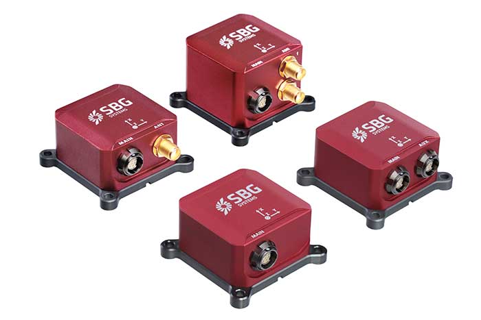
Third Generation of the Ellipse Series of IMUs. Clockwise from top: Models D, E, A and N. (Photo: SBG Systems)
Not just supporting players, alternative positioning, navigation and timing (PNT) systems strengthen, augment and — when needed — replace GNSS. GPS World explores how companies are using alternative PNT, and talks with Alexis Guinamard of SBG Systems about the company’s latest developments.
GPS World: What are the main challenges to GNSS that require developing alternatives?
Alexis Guinamard: GNSS technology can be easily disturbed by a wide variety of factors. Urban canyons or foliage environments can obstruct GNSS signals or cause multipath effects. Intentional and unintentional jamming and spoofing are also a big concern for PNT users.
Alternative technologies are developed to add robustness to GNSS positioning and useful features like orientation tracking (inertial + GNSS), or ultimately to work in pure GNSS-denied environments (SLAM).
GPS World: What is your range of products?
AG: We develop and produce GNSS-aided inertial navigation systems, but also provide a post-processing software (Qinertia). Our latest innovation is the third generation of the Ellipse series — our best-selling product — which is an industrial-grade INS. Based on the same inertial core, we integrated cutting-edge technologies, such as a multi-frequency GNSS receiver and RTK capability, within a miniature form factor.
A multi-constellation, multi-frequency receiver is much harder to jam or to spoof, which makes the Ellipse-N very robust and able to operate despite interference.
Finally, the new Ellipse-D, which provides dual-antenna heading capability, has been drastically improved in terms of size, weight and power.
Our post-processing software is compatible with all our INS products. So, we can post-process these data to obtain centimeter precision in a PPK mode. Qinertia is running a tightly coupled navigation filter to obtain the best navigation performance in post-processed applications.Thanks to the raw data output of the Ellipse’s sensors, it’s really straightforward to do post-processing with Qinertia PPK software and obtain the highest level of accuracy.
We worked hard to make the user experience as easy as possible. The latest version of Qinertia allows the customer to process either INS systems with GNSS or purely GNSS data.
GPS World: What are primary uses of your systems?
AG: We have many advanced robotics applications, including UAV, driverless cars, and agricultural robots. We divide them into mapping applications, remote-sensing applications and control applications.
Inertial sensors can help a lot for the control applications because we are able to reject false GNSS measurements in both loosely and tightly coupled schemes. We can also use them to provide a precise heading, which is required by many of these applications. So, I would say that advanced robotics is one of the major growth areas for us.
Not just supporting players, alternative positioning, navigation and timing (PNT) systems strengthen, augment and — when needed — replace GNSS. GPS World explores how companies are using alternative PNT, and talks with John Fischer of Orolia about the company’s latest developments.
GPS World: What are Orolia’s latest advances and products regarding alternative PNT?
John Fischer: Regarding timing, which we have been doing for decades, our big alternatives to GNSS are internal atomic clocks and network-based timing, such as precision time protocol (PTP). Regarding positioning and navigation, the two areas on which we focus are IMUs and getting updates from GNSS, so that, when you lose GNSS momentarily, you have something on which to coast. The breakthroughs in MEMS technologies are astounding —they are getting better and cheaper every day. That shows wonderful promise.
The other area is doing satellite navigation using low Earth orbit (LEO) satellites, which are much closer to the Earth than GNSS ones and give you 30 dB or more of signal strength. We are focused the most on the Satellite Time and Location (STL) signal because it is available today. Supplementing your navigation system with updates from LEO satellites provides you some great non-GNSS navigation capability.
GPS World: The positions of LEO satellites are not monitored as closely as those of GPS satellites. Is that an issue?
JF: That is correct. You are losing accuracy by using what is available today because you do not know the positions of those satellites as well as you know those of the GNSS satellites and maybe you do not have the best geometry. All the GNSS satellites are in medium Earth orbit (MEO) because they have much better geometries for a small constellation. With just 24 satellites in MEO orbit, you get great geometries. When you go lower, you need an increasingly greater number of satellites.
The first generation of LEO satellites, the Iridium STL, are a much larger constellation, with 66 satellites, but still not enough to give you the good geometries. Today, you are getting less accuracy, but there are all kinds of new satellites being launched and the capability to track them will improve. We expect to be able to use signals from hundreds, if not thousands, of LEO satellites, so the geometry problem will start to go away and there are other things we can do to improve the accuracy. Meanwhile, we can get rather good performance with what we have today.
GPS World: What are some of your most recent advances, releases or products?
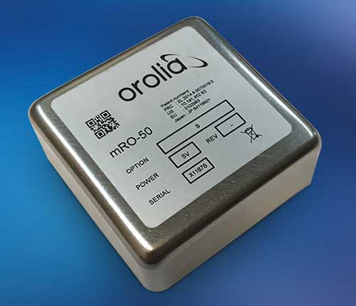
JF: On the timing side we have what we call a mini-Rubidium, the mRO-50, which we launched on June 4. Smaller, better, cheaper atomic clocks are coming out very soon.
GPS World: Do you have any comments on the recent executive order on resilient PNT?
JF: We coined the term “resilient PNT,” so we are glad to see it in use. We fully support those efforts.
GPS World: What about other alternative sources of PNT data, such as radar, lidar and signals of opportunity?
JF: Yes, they are that next level. Loran is ideal because it is so different from GNSS. When you are trying to design a reliable system, you want a lot of diversity, because if two systems have the same kinds of failure modes you have not gained in redundancy. Loran is literally at the other end of the spectrum from GNSS: It is a low-frequency microwave system. Instead of being space-based, it is land-based; instead of being low power, it is high power. However, there still are no stations up. It requires big equipment, so it will take some time.
When it comes to what you can do today, Loran does not contribute much. We support efforts to implement Loran very much, because we do need non-GNSS ways to make things resilient. Prior to GPS, we had to depend only on Loran. Today, with modern digital signal processing (DSP) techniques and receivers, I think we can expect the new Loran system to have much better accuracies than we had in the bad old days of the first generation of Loran.
The auto industry is doing a marvelous job of doing navigation using lidar or cameras. They are pretty much navigating driverless cars the way that humans drive, by just using visual cues. Those things have promise in certain unique areas.
Two F-16 Fighting Falcons fly over Edwards AFB during a 2009 air show. (Photo: U.S. Air Force/Chad Bellay)
The U.S. Air Force in September will begin testing on F-16’s an alternative position, navigation and timing (PNT) solution that uses the Earth’s magnetic anomalies.
The navigation technique, dubbed MAGNAV, is being researched at the Air Force Institute of Technology (AFIT), reports Forbes.
Air Force Major Aaron J. Canciani, an Assistant Professor of Electrical Engineering at AFIT, designed algorithms for MAGNAV flight testing on F-16s. Testing has already taken place using private survey aircraft.
MAGNAV sensors and software will be flown on Air Force Test Pilot School (AFTPS) F-16s over a special test range adjacent to Edwards Air Force Base in Nevada.
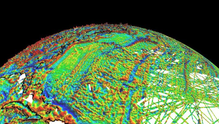
Magnetic anomaly navigation uses scalar magnetometer sensors that measure differences in the magnitude of magnetic fields when traveling past them. These variations can be compared with known features in magnetic field maps and be interpreted to determine position.
The four pillars of MAGNAV are magnetic maps, sensors, algorithms and calibration. The magnetic maps already exist within industry, the military and government agencies including NOAA, NASA, NGA and more.
NOAA’s EMAG2 (v3) World Digital Magnetic Anomaly Map. (Image: NOAA National Geophysical Data Center)
In 2018 the first-ever European Radionavigation Plan said “It is recognized that [..] GNSS should not be the sole source of PNT information. Alternative PNT systems, not necessarily using radio frequencies, should thus be put in place where the criticality of the application requires it.”
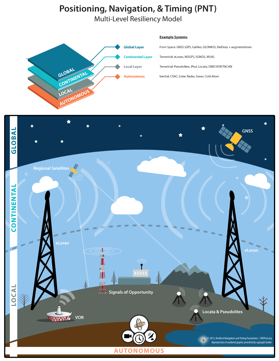
Graphic from MarRINav report showing system of systems approach to PNT resilience and reliability. (Image: Resilient Navigation and Timing Foundation)
In 2019 the European Space Agency (ESA) published a permanent open call for proposals for positioning, navigation, and timing studies and systems, including those that had nothing to do with space.
“Maritime navigation and port operations are critical for almost every nation,” said Jonathan Turner, one of the MarRINav project team. “As an island nation with a strong maritime heritage, we in the United Kingdom perhaps have an even greater appreciation of this.” Turner is co-founder of the blue economy solutions company NLA International, which led a team of eight organizations cooperating on the project.
While MarRINav focused its analysis on the United Kingdom, the intent was to provide information, and an analysis framework, that could also be used by other nations.
Maritime is one of sectors most dependent upon GNSS, according to the project reports, and a sector with great awareness of GNSS vulnerabilities and their consequences. MarRINav concludes that integrity and resilience are two of the most important parameters for maritime navigation.
Maritime is also one of the sectors most ready to integrate space and terrestrial navigation systems, according to the report’s authors. The International Maritime Organization has already introduced a performance standard for a multi-system receiver, or MSR, that will incorporate a wide variety of navigation signals.
Despite the distractions of Brexit over the last four years, the United Kingdom has been particularly focused on its vulnerability to GNSS outages.
In February of this year the UK government announced it was establishing a virtual National Timing Centre to protect the nation from the risk of GNSS failure, and in March the final MarRINav report was published.
Among the project’s findings are that:
The United Kingdom needs a comprehensive maritime PNT architecture with multiple, diverse sources to ensure continuity of maritime operations
Such a “hybrid solution” could benefit other sectors, especially if non-maritime needs were considered early in the design
New PNT systems should be terrestrial and sovereign
Establishing such a system for the UK has a very positive benefit to cost ratio
Important aspects of the new architecture are E-GNSS (Galileo and EGNOS), Enhanced Loran (eLoran) and the Ranging Mode (R-Mode) of the VHF Data Exchange System (VDES), and complemented by the development of a specific Maritime Receiver Autonomous Integrity Monitoring (M-RAIM) algorithm.
LOCATA or a similar local positioning system should be implemented at UK ports to provide a backup for container operations.
Satelles Satellite Time and Location may have potential, but its utility has yet to be demonstrated for maritime.
Now the company has released from new tests using configurations with a differential source and with a more accurate OCXO clock, producing timing accuracy of 160 nanoseconds.
Gregory Gutt, president and chief technical officer of Satelles, made the presentation at the recent Institute of Navigation International Technical Meeting.
The 66-satellite Iridium LEO constellation transmits overlapping spot beams, which provide location-specific data that changes every few seconds. The featured image on this article (above) shows spot beam pattern for 2 of 66 satellites.
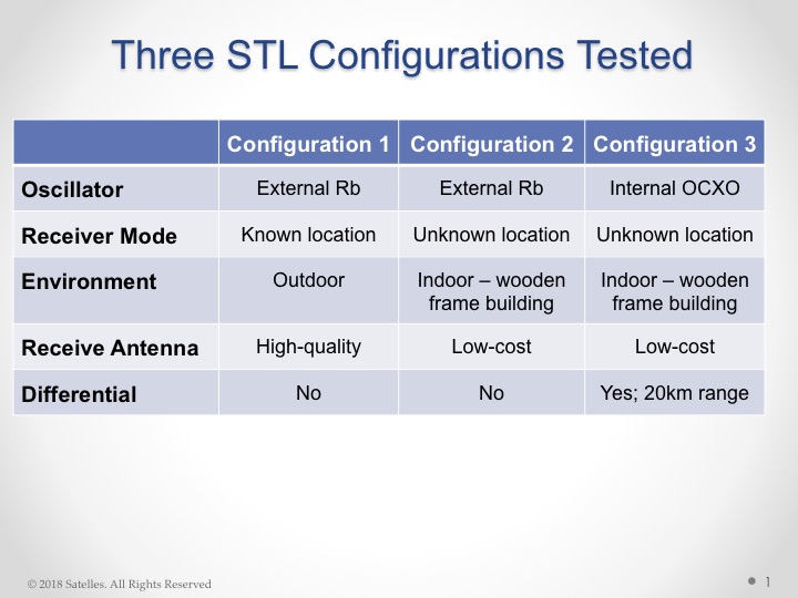
Overview of Satelles test configurations. (Chart: Satelles)
The testing employed three different configurations of equipment, services, and environment, as shown in the adjacent figure. Equipment employed in the tests included a Stanford Research Systems (SRS) rubidium vapor frequency reference, based on the PRS10 module, and a Satelles Evaluation Kit (EVK2) STL receiver, comprising a Maxim RF chip, Xylinx Spartan-3 FPGA , TI dual core DSP chip, and internal OCXO or external clock.
Parameters and equipment for the three test configurations:
Configuration #1 – Optimal. Outdoor antenna, Rubidium clock powered on for months prior to data collection, receiver configured in static mode with a known location, and high-quality antenna
Configuration #2 – Sub-optimal. Indoor antenna, Rubidium clock powered on 6 hours prior to data collection, receiver configured in static mode with an unknown location, and low quality antenna
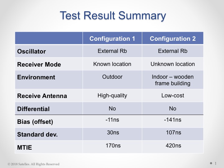
Results from the first two tests are shown here:
Test results, configurations 1 and 2. (Chart: Satelles)
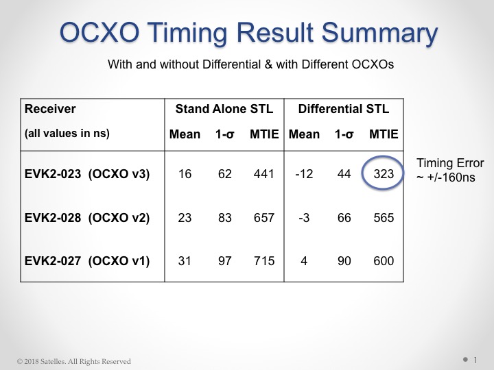
Configuration #3. Three independent receivers collecting data, receiver on-board OCXO, indoor antenna, receiver configured in static mode with an unknown location, low-quality antenna. Tests performed:
10 days with no local reference station running
10 days with local reference station, 20km away from test receivers, providing timing corrections to STL ground segment.
Results from these tests shown here:
Results from OCXO tests. (Table: Satelles)
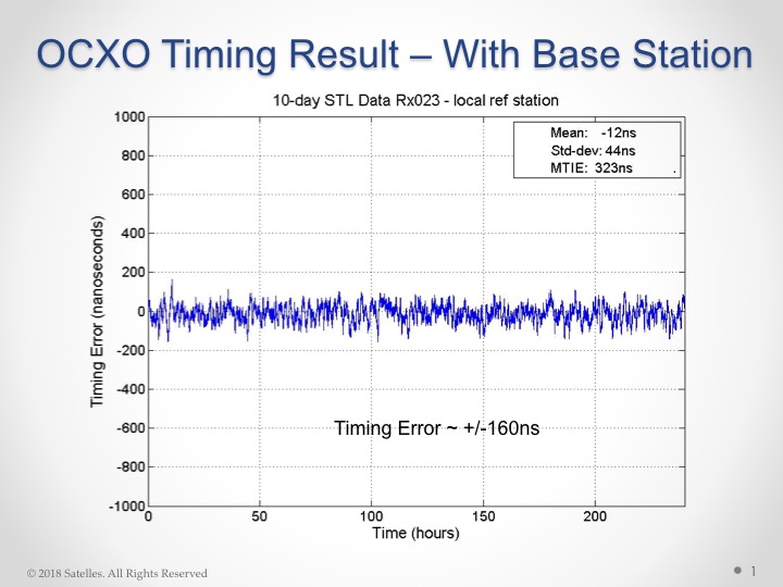
With this individual test result:
OCXO timing result with base station. (Chart: Satelles)
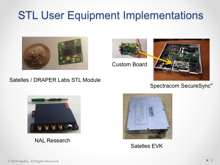
Some of the commercially available products and evaluation kits that incorporate the STL service are shown here:
STL user equipment implementations. (Image: Satelles)
Editor’s Note: This online preview presents brief highlights from the upcoming July cover story in GPS World, “Navigation from LEO: Current Capability and Future Promise.” The article is by David Lawrence, H. Stewart Cobb, Greg Gutt, and Michael O’Connor of Satelles, Tyler G. R. Reid and Todd F. Walter of Stanford University, and David Whelan.
Robust position, navigation, and timing services from low Earth orbit (LEO) are here today, providing augmentation to GPS where GPS isn’t available. The addition of navigation signals from LEO provides a number of benefits. The proximity of LEO satellites has the potential to provide much stronger signals than the distant GNSS core-constellations like GPS in medium-Earth orbit (MEO).
Today, the only LEO system with global coverage is the Iridium constellation used primarily for communications.
Figure 1 shows the 31-satellite GPS constellation in contrast with the 66-satellite Iridium network. The scale of the difference in distance (several Earth radii) is extraordinary. The result is that Iridium signals are 300 to 2400 times stronger than GNSS signals on the ground, making them attractive for use in position, navigation, and timing (PNT) applications where GNSS signals are obstructed.
Figure 1. The 66 satellite Iridium constellation in low Earth orbit and 31 satellite GPS constellation in medium Earth orbit.
LEO-based PNT is now mainstream, in the form of real-time signals that have been delivered over the Iridium satellite network since May 2016. This service is made possible by Satelles in partnership with Iridium Communications Inc. in a service called the Satellite Time and Location (STL), a non-GNSS solution for assured time and location that is highly resilient and physically secure. Consumers, businesses, and governments are already using these LEO-based signals in environments with high GNSS interference or occlusion.
The security features of these signals are also used to reliably validate GNSS position, navigation and time (PNT) solutions in real time to help mitigate potential spoofing. Furthermore, the fast LEO orbits of Iridium generate Doppler-frequency signatures significantly stronger than GPS, increasing the utility of the STL signal for positioning applications.
STL field tests demonstrate a positioning accuracy of 20 meters and timekeeping to within 1 microsecond, all in deep attenuation environments indoors. This adds substantial robustness in augmenting the GNSS core-constellations like GPS and also allows for a standalone backup in many applications.
Along with its strong signals compared to the GNSS core-constellations in MEO, Iridium’s global coverage makes it ideal for use in PNT applications where GNSS is obstructed. Figure 1 shows the scale of the difference in altitude with Iridium at 780 kilometers and GPS at 20,200 kilometers. This has substantial implications not only for signal strength but also for coverage.
Though Iridium has twice as many satellites as GPS, at the equator users can often only see one satellite whereas they can see ten from GPS. This was one of the fundamental trades considered in the design of the GPS constellation. The higher the altitude, the more each launch cost; the lower, the more satellites had to be built to provide coverage. To put this in perspective, global coverage for one satellite in view at all times requires fewer than ten satellites in MEO but requires closer to one hundred in LEO.
Future LEO Constellations
The hundreds of LEO satellites needed to match the coverage of GPS may be coming. In late 2014 and early 2015, the International Telecommunication Union (ITU) reported a half dozen filings for spectrum allocation for large constellations of LEO satellites.
In January 2015, OneWeb announced a partnership with Virgin and Qualcomm to produce a constellation of 648 LEO satellites to deliver broadband Internet globally. This represents the next order of magnitude, with tenfold more satellites than Iridium. Within days of this announcement, SpaceX, with support from Google, announced a similar ambition for a constellation of more than 4,000 LEO satellites.
In August 2015, Samsung expressed interest in a proposal for a LEO constellation of 4,600. Boeing joined the race in June 2016 announcing plans for a LEO constellation of nearly 3,000 satellites. These LEO constellations are being proposed to keep up with the rising demand for broadband, not to replace ground infrastructure.
LEO versus MEO
Low- and medium-Earth orbit each have their individual strengths and weaknesses in the context of navigation. Closer to Earth, LEO offers less spreading loss and improved signal strength on the ground. On the other hand, being closer to Earth means that satellites have much smaller footprints. The GPS footprint is threefold larger than Iridium, corresponding to nine times more area covered. Hence, to achieve the same coverage as GPS with Iridium’s altitude, the LEO constellation requires an order of magnitude more satellites.
Another major difference between LEO and MEO is speed. A GPS satellite completes one Earth revolution every 12 hours while an Iridium one does so in only 100 minutes. The shorter the orbital period, the faster the angular rate (also called mean motion) and the more quickly satellites pass overhead.
The swift motion whitens multipath (making it more random–like white noise) as reflections are no longer effectively static over short averaging times. Geometric diversity also leads to effective Doppler positioning and is also desirable for carrier-phase differential GNSS, allowing for much more rapid resolution of integer cycle ambiguities.
Iridium-Satelles Satellite Time and Location (STL)
The STL service has been in operation since May 2016. Many from industry and government are already using this service to achieve a more robust PNT solution. This service will only continue to improve with the Iridium NEXT satellites under deployment; the first ten satellites of this generation were successfully launched in January 2017.
STL is a non-GNSS solution for assured time and location that is highly resilient and physically secure. STL utilizes the Iridium constellation to transmit specially structured time and location broadcasts. Due to their high RF power and signal-coding gain, the STL broadcasts are able to penetrate into difficult attenuation environments, including deep indoors.
Like GNSS signals, these broadcasts are specifically designed to allow an STL receiver to obtain precise time and frequency measurements to derive its PNT solutions. STL is able to augment or serve as a backup to existing GNSS PNT solutions by providing secure measurements in the presence of high attenuation (deep indoors), active jamming, and/or malicious spoofing.
Unlike the MEO GNSS satellites, Iridium uses 48 spot beams to focus its transmissions on a relatively small geographic area. The complex overlapping spot beams of Iridium combined with randomized broadcasts give a unique mechanism to provide location-based authentication that is extremely difficult to spoof.
The July cover story in GPS World magazine will explore all the above topics in more technical detail, and go further into the areas of signal strength in challenging environments, indoor time-transfer capability, and a section on looking forward.
The PNT service using Iridium is perhaps a sign of things to come. On the horizon are constellations like OneWeb which promise the next order of magnitude with 648+ satellites, slated for the 2020s. This most recent scale gives rise to better satellite geometry than GPS today with the added benefits of LEO.
The STL signal using Iridium sets a precedent that could lead to unparalleled navigation services that are robust due to the improved signal strength and precise due to the huge number of LEO satellites coming, each moving quickly and giving the geometric diversity needed to enable fast carrier-phase differential GNSS.
The need for such a service is already present. This would be enabling for the safety-critical autonomous vehicles under development that must operate in challenging urban environments and to a diversity of other future technologies and applications as well.
It has been a good year for all global navigation satellite systems (GNSS), as the chief executives of each system testify here. Alternative positioning, navigation and timing (PNT) also thrives. In this roundup of the latest highlights from the past year and forecasts for the future, 2017 augurs very well indeed! Let’s look at the newest alternative-PNT offerings first, followed by forecasts from the chief executive officers (CEOs) of each of the conventional GNSS.
Alternative PNT grows and expands
Two new entrants to the positioning, navigation and timing (PNT) marketplace offer key capabilities to fill in the gaps left by GNSS. A new satellite timing and location (STL) service from low-Earth orbit satellites, provided by Satelles and Orolia, gives a strong signal capable of penetrating buildings.
Satellite Time and Location (STL) Service. Pursuant to a recent announcement of new PNT solutions independent of GPS/GNSS signals, provided via the Iridium constellation, GPS World talked with Jean-Yves Courtois, CEO of Orolia. Orolia has partnered with Satelles to bring new PNT products and services to the global market, with a focus on military, and defense, government and commercial customers worldwide.
Jean-Yves Courtois, CEO of Orolia.
“We are a manufacturer and integrator of timing equipment,” Courtois said. Orolia is the parent company of GPS/GNSS product and service providers Spectracom, McMurdo and Spectratime. “This new STL service is not fully commercialized yet, but it’s operational and it can be tested. Receivers are available and can be integrated into our equipment.
“The timing signal is very accurate and close enough to GPS for most timing applications, although the positioning accuracy is lower than what GPS users are used to. It is an augmentation for timing primarily, and secondarily for positioning.
“In terms of timing accuracy, it provides on the order of tenths of microseconds in accuracy, and this covers a lot of timing applications, very familiar to us and to our customers. This is an ideal timing backup or augmentation of GPS. As number 2 worldwide in high-precision timing, we know this market and its applications very well.”
Correlator beamforming. The Locata Corporation announced a patented correlator beamforming technology to stem multipath mitigation. The new technique’s performance under rigorous testing by the U.S. Air Force Institute of Technology will be detailed in the January 2017 issue. Look for it! Here are a series of snippets as a preview of that lengthy technical article appearing in Richard Langley’s Innovation column.
“Unlike conventional or traditional beamsteering technology, the new correlator beamforming approach combines RF signals received by any number of individual antenna elements into a single switched-RF signal. This time-multiplexed signal is then downconverted and digitized by a single RF front-end. The correlator beamforming design will should offer cost savings because the resulting data stream is processed using a single correlator channel per beam. This markedly reduces the complexity when compared to the traditional beamsteering methodology.
“The correlator beamforming technique performs antenna array signal processing to form beams as part of a receiver’s correlation process. The complete explanation of this technology can quickly get complex, even for the seasoned RF engineer. To describe this process more simply, we will assume noiseless signals and no multipath (except as noted), as well as equal noise figures for all front-end processing chains. To further simplify our explanation, modulation on the carrier and switching losses will be ignored.”
“To evaluate the performance of correlator beamforming as fairly as possible compared to traditional beamsteering and single-element processing, AFIT set up its data collection such that all three approaches could be implemented in a software receiver. Additionally, a seven-element Naval Air Systems Command GPS Antenna System 1 (GAS-1) antenna was used for this experiment. The antenna was mounted on a 51-inch (130-centimeter) diameter rolled-edge ground plane provided to the ANT Center by the MITRE Corporation.”
“The testing focused on demonstrating an easily modified GNSS receiver to potentially deliver a low-cost solution for mitigating multipath — specifically targeting short delay and carrier multipath. The results presented here show that the multipath rejection performance nearly equals that of a traditional beamsteering GNSS receiver. Applications that can significantly benefit from this technology include stationary GNSS monitoring installations such as those used in satellite-based and ground-based augmentation systems and GNSS receivers for autonomous vehicles and UAVs in high multipath areas such as urban canyons.”
GPS III ready, steady
Col. Steve Whitney, Director, U.S. Air Force GPS Directorate
“The [GPS III] program is working to solve several technical challenges as we progress to completion,” Col. Steve Whitney, director of the U.S. Air Force GPS Directorate, wrote in GPS World’s December issue. “SV-01 testing uncovered electro-magnetic interference between a payload component and a hosted payload. Testing also uncovered electron impact issues on the L-band antenna elements. In partnership with Lockheed Martin, the program developed corrective action and design mitigations for both of these issues and is implementing these steps within our production flow for all the SVs.”
“In the coming year, SV-02, the second GPS III satellite, will also be progressing towards completing production. Currently, all of the SV-02 sub-assemblies have been received by Lockheed Martin and are being integrated into the spacecraft. The next major step in the production flow for SV-02 will be to mate it with its propulsion core.
“Recently, we completed negotiations with Lockheed Martin to extend the production line with purchases of SV-09 and SV-10. These satellites will be technically equivalent to SV-01 through SV-08. This $395 million purchase of two satellites marks a significant affordability milestone for the procurement of GPS III satellites.
“Looking ahead, we are analyzing how to acquire satellites beyond SV-10. We are executing a phased strategy which starts first with determining the viability of a GPS III production design existing beyond the current contractor. We awarded an initial phase of contracts to the Boeing Company, Lockheed Martin Space Systems Company, and Northrop Grumman Aerospace Systems in May 2016 to provide a feasibility assessment of the readiness of their satellites designs. In this phase, the contractors will provide a GPS III production design, manufacturing plans and a navigation payload brassboard test report, along with manufacturing/production processes and facilities maturity.”
Galileo coming on strong
Director of the Galileo Programme Paul Verhoef of the European Commission wrote in that same issue of the magazine, “The production of the satellites continues to maintain a steady rhythm, with a production line stretching from suppliers across Europe to OHB and SSTL and then to ESA’s ESTEC Test Centre in the Netherlands for acceptance testing, based on a wide range of simulated space tests.”
Paul Verhoef, director of the Galileo Programme and Navigation-related Activities, European Space Agency.
“The acceptance of the next satellites to launch is scheduled for this year’s end,” continued Verhoef. “Along with the two more Ariane 5 launches to come — one in the second half of 2017 and another in 2018 — the current plan is to commission further launch services as well as additional satellites in order to have Galileo fully operational by 2020. For these launches, Galileo may be the first customer of the new Ariane-6 launch vehicle.
“2017 will see the upgrade of various elements of the Galileo Ground Segment to reinforce its robustness, including updated releases to the Galileo Control Segment overseeing the satellites and the Galileo Mission Segment, overseeing the navigation signals. A new release of elements of the Galileo Security Facility, for security monitoring of the system, as well as the secure Public Regulated Service, will be deployed at the two Galileo Security Monitoring Centres.
“The Galileo Ground Segment will gain a sixth tracking telemetry and control facility, for monitoring the satellite platforms in Papeete, Tahiti, and additional processing chains for increased redundancy will be deployed across the Uplink Stations in Kourou, Reunion and Noumea used to update the navigation message information. Similar redundant chains will be finalized for all 15 current Galileo Sensor Stations, which perform continuous collection of Galileo signals to identify the tiniest clock error or satellite drift.”
EGNOS. “Along with the progress of Galileo, contracts are planned to cater for the further development of the ESA-designed European Geostationary Navigation Overlay Service, Europe’s first navigation system. EGNOS was certified for safety-of-life aviation use in 2011, and is managed by the European Commission through a contract with operator the European Satellite Services Provider, based in France. ESA will support the technical evolution of EGNOS version 3, intended as multi-constellation in nature, again through the Horizon 2020 framework.”
GLONASS looks forward to a new signal: CDMA!
Sergey Karutin, GLONASS Chief Designer, wrote “On the threshold of the first GLONASS-K2 launch, new GLONASS reference documents were published in October 2016, describing the family of code-division multiple-access (CDMA) radionavigation signals. The draft GLONASS Open Service Performance Standard has been developed. The GLONASS User Information Support System continues to evolve.”
From left: Sergey Karutin, GLONASS designer general; Nicolay Testoedov, director general, SC Information Satellite Systems; and Andrey Tulin, director general, SC Russian Space Systems.
“The system transmitting CDMA navigation signals is referred to in four interrelated interface control documents containing general information on signals and the detailed description of signal structures and digital message data. The new signals make it possible to include 63 satellites in the constellation, not only in circular medium-Earth orbit but also on geostationary and high-Earth orbits.
“The transition to the flexible string-type structure of the message data produces 2-second periodicity of integrity information delivery to users. The increased number of digits occupied by the ephemeris and clock parameters contributes to a better orbit and clock broadcast accuracy. The ephemeris broadcast precision improves from 0.4 to 0.001 meters. Time-stamp length in CDMA signal has increased to 30 bits, compared to 12 bits of frequency-division multiple-access signals.”
BeiDou approaches full regional services
Li Wang
“In 2017, three to four launches of BeiDou satellites will occur,” wrote Li Wang, Director of the International Cooperation Center in China’s Satellite Navigation Office. “BDS will provide basic services to the countries along the Belt and Road region by 2018, and possess global service capability by 2020.”
“BDS will keep improving its nationwide reference station network and steadily enhance its service performance. The dense reference stations for the nationwide frame network will be constructed by 2018, providing meter and decimeter level real-time location services for users in China, even centimeter level service in some areas.
“BDS will carry out the design, validation and construction of SBAS in accordance with international civil aviation standards. The first GEO satellite of BDSBAS will be launched in around 2018. The satellite-based augmentation services covering China and surrounding regions will be provided from 2020, to provide CAT-I services to civil aviation users.
“China will promote construction of a national comprehensive positioning, navigation and timing (PNT) system based on BDS, and strive to establish such a national PNT system with a united benchmark, no-gap coverage, security and effectiveness by 2030, as well as to upgrade capabilities to provide time and space information.”
Pursuant to a recent announcement of new PNT solutions independent of GPS/GNSS signals, provided via the Iridium constellation, GPS World talked with Jean-Yves Courtois, CEO of Orolia. Orolia has partnered with Satelles to bring new PNT products and services to the global market, with a focus on military, and defense, government and commercial customers worldwide.
Jean-Yves Courtois, CEO of Orolia.
“We are a manufacturer and integrator of timing equipment,” Courtois said. Orolia is the parent company of GPS/GNSS product and service providers Spectracom, McMurdo and Spectratime. “This new STL service is not fully commercialized yet, but it’s operational and it can be tested. Receivers are available and can be integrated into our equipment.
“The timing signal is very accurate and close enough to GPS for most timing applications, although the positioning accuracy is lower than what GPS users are used to. It is an augmentation for timing primarily, and secondarily for positioning.
“In terms of timing accuracy, it provides on the order of tenths of microseconds in accuracy, and this covers a lot of timing applications, very familiar to us and to our customers. This is an ideal timing backup or augmentation of GPS. As number 2 worldwide in high-precision timing, we know this market and its applications very well.”
The STL signal strength is much greater than GNSS because the LEO satellites are much closer. (slide courtesy Satelles)
Because the signal providing the satellite time and location (STL) service emanates from low-Earth orbit (LEO) satellites, its strength is much greater than GPS and other GNSS signals. Among its key characteristics: it gets good reception inside buildings and beneath other obstructions.
“The STL signal works very well,” Courtois continued. “We were surprised. Satelles is very conservative in their statements, and we got better results than they promised in our tests. They under-promised and over-delivered. It penetrates buildings well, it has unique features and it performs at a high level. So we decided to invest in it. All our engineers are excited about it!
“In positioning it’s closer to fifty meters or more. Much better for fixed objects than for mobile objects. The more mobile, the faster the vehicle, then the lower the positioning accuracy. It’s not directly usable for GPS applications that require a few meters accuracy, but it can be associated with inertial navigation for much better results.
“The signal is encrypted, so you have to subscribe to a service to receive a key, allowing access to the signal.
“Applications are developing based on equipment that will be STL-enabled. For the user it will be transparent. The user will have a different antenna.
“We are also active in tracking and emergency location devices, where this is also of interest. It has some authentication capability, to guarantee that the person who accesses the signal is in the location that he pretends to be.”
“For customers to be able to use this service, there is some integration work to be done, some dedicated STL receivers to integrate into our current hardware set up, and software modifications. Our engineers are ready, we are all ready to work with government and defense organizations and other new clients.”
“Our basic interest is to add some robustness to our equipment for our current customers, and then of course to develop new customers worldwide.”
Exploiting terrestrial signals of opportunity (SOPs) can significantly reduce the vertical dilution of precision (VDOP) of a GNSS navigation solution. Simulation and experimental results show that adding cellular SOP observables is more effective in reducing VDOP than adding GNSS space vehicle (SV) observables.
By Joshua J. Morales, Joe J. Khalife and Zaher M. Kassas
GNSS position solutions can in many cases suffer from a high vertical dilution of precision (VDOP) due to lack of space vehicle (SV) angle diversity. Signals of opportunity (SOPs) have been recently considered to enable navigation whenever GNSS signals become inaccessible or untrustworthy. Terrestrial SOPs are abundant and are available at varying geometric configurations, making them an attractive supplement to GNSS for reducing VDOP.
Common metrics used to assess the quality of the spatial geometry of GNSS SVs are the parameters of the geometric dilution of precision (GDOP); namely, horizontal dilution of precision (HDOP), time dilution of precision (TDOP), and VDOP. Several methods have been investigated for selecting the best GNSS SV configuration to improve the navigation solution by minimizing the GDOP. While the navigation solution is always improved by additional observables from GNSS SVs, the solution’s VDOP generally remains of lesser quality than the HDOP. GPS augmentation with terrestrial transmitters that transmit GPS-like signals have been shown to reduce VDOP. However, this requires installation of additional proprietary infrastructure.
This article studies VDOP reduction by exploiting terrestrial SOPs, particularly cellular code division multiple access (CDMA) signals, which have inherently low elevation angles and are free to use.
In GNSS-based navigation, the states of the SVs are readily available. For SOPs, however, even though the position states may be known a priori, the clock-error states are dynamic; hence, they must be continuously estimated. The states of SOPs can be made available through one or more receivers in the navigating receiver’s vicinity. Here, the estimates of such SOPs are exploited and the VDOP reduction is evaluated.
PROBLEM FORMULATION
Consider an environment comprising a receiver, M GNSS SVs, and N terrestrial SOPs. Each SOP will be assumed to emanate from a spatially stationary transmitter, and its state vector, xsop(n), will consist of its three-dimensional (3-D) position rsop(n) and clock bias cδtsop(n), where n=1,…,N and c is the speed of light. The receiver draws pseudorange observations from the GNSS SVs and from the SOPs. The observations are fused through an estimator whose role is to estimate the state vector of the receiver xr=[rrT, cδtr] T, where rr and cδtr are the 3D position and clock bias of the receiver, respectively. To simplify the discussion, assume that the pseudorange observation noise is independent and identically distributed across all channels with variance σ2. The estimator produces an estimate of the receiver’s state vector and associated estimation error covariance P =σ2(HTH)-1.
Without loss of generality, assume an East-North-Up (ENU) coordinate frame to be centered at . In this frame, the dilution of precision matrix G≡(HTH)-1 is completely determined by the azimuth and elevation angles from the receiver to each SV, denoted azsv(m) and elsv(m), respectively, and the receiver to each SOP, denoted azsop(n) and elsop(n), respectively, where m=1,…,M. Hence, the quality of the estimate depends on these angles and the pseudorange observation noise variance σ2. The diagonal elements of G, denoted gii, are the parameters of the dilution of precision (DOP) factors:
Therefore, the DOP values are directly related to the estimation error covariance; hence, the more favorable the azimuth and elevation angles, the lower the DOP values. If the observation noise was not independent and identically distributed, the weighted DOP factors must be used.
VDOP REDUCTION VIA SOPs
With the exception of GNSS receivers mounted on high-flying and space vehicles, all GNSS SVs are typically above the receiver, that is, the receiver-to-SV elevation angles are theoretically limited between 0°≤elsv(m)≤90°. GNSS receivers typically restrict the lowest elevation angle to some elevation mask, elsv,min, so to ignore GNSS SV signals that are heavily degraded due to the ionosphere, troposphere and multipath.
As a consequence, GNSS SV observables lack elevation angle diversity, and the VDOP of a GNSS-based navigation solution is degraded. For ground vehicles, elsv,min is typically between 5° and 20°. These elevation angle masks also apply to low-flying aircraft, such as small unmanned aerial vehicles (UAVs), whose flight altitudes are limited to 500 feet (approximately 152 meters) by the Federal Aviation Administration (FAA).
In GNSS + SOP-based navigation, the elevation angle span may effectively double, specifically –90°≤elsop(n)≤90°. For ground vehicles, useful observations can be made on terrestrial SOPs that reside at elevation angles of elsop(n)=0°. For aerial vehicles, terrestrial SOPs can reside at elevation angles as low as elsop(n)=–90°, for example, if the vehicle is flying directly above the SOP transmitter.
To illustrate the VDOP reduction by incorporating additional GNSS SV observations versus additional SOP observations, an additional observation at elnew is introduced, and the resulting VDOP(elnew) is evaluated. To this end, M SV azimuth and elevation angles were computed using GPS ephemeris files accessed from the Yucaipa, California, station from Garner GPS Archive, which are tabulated in Table 1.
Table 1. SV azimuth and elevation angle (degrees).
For each set of GPS SVs, the azimuth angle of an additional observation was chosen as a random sample from a uniform distribution between 0° and 360°, that is, aznew~U(0°,360°). The corresponding VDOP for introducing an additional measurement at a sweeping elevation angle –90°≤elnew≤90° are plotted in Figure 1 (a)–(d) for M=4,…,7, respectively.
Figure 1. A receiver has access to M GPS SVs from Table 1. Plots (a)- (d) show the VDOP for each GPS SV configuration before adding an additional measurement (red dotted line) and the resulting VDOP(elnew) for adding an additional measurement (blue curve) at an elevation angle –90°≤elnew≤90° for M=4,…,7, respectively.
The following can be concluded from these plots. First, while the VDOP is always improved by introducing an additional measurement, the improvement of adding an SOP measurement is much more significant than adding an additional GPS SV measurement. Second, for elevation angles inherent only to terrestrial SOPs, that is, –90°≤elsop(n)≤0°, the VDOP is monotonically decreasing for decreasing elevation angles.
SIMULATION RESULTS
To compare the VDOP of a GNSS-only navigation solution with a GNSS + SOP navigation solution, simulations were conducted using receivers mounted on ground and aerial vehicles.
Ground Receiver. The position of a receiver mounted on a ground vehicle was set to rr ≡(106 )•[– 2.431171,– 4.696750, 3.553778]T expressed in an Earth-Centered-Earth-Fixed (ECEF) coordinate frame. The elevation and azimuth angles of the GPS SV constellation above the receiver over a 24-hour period was computed using GPS SV ephemeris files from the Garner GPS Archive. The elevation mask was set to elsv,min≡20°. The azimuth and elevation angles of three SOPs, which were calculated from surveyed terrestrial cellular CDMA tower positions in the navigating receiver’s vicinity, were set to azsop≡[42.4°,113.4°,230.3° ]T and elsop ≡[3.53°,1.98°,0.95°]T, respectively. The resulting VDOP, HDOP, GDOP and associated number of available GPS SVs for a 24-hour period starting from midnight, Sept. 1, 2015, are plotted in Figure 2.
Figure 2. Fig. (a) represents the number of SVs with an elevation angle >20° as a function of time. Fig. (b)-(d) correspond to the resulting VDOP, HDOP, and GDOP, respectively, of the navigation solution using GPS only, GPS + 1 SOP, GPS + 2 SOPs, and GPS + 3 SOPs.
The following can be concluded from these plots. First, the resulting VDOP using GPS + N SOPs for N≥1 is always less than the resulting VDOP using GPS alone. Second, using GPS + N SOPs for N≥1 prevents large spikes in VDOP when the number of GPS SVs drops. Third, using GPS + N SOPs for N≥1 also reduces both HDOP and GDOP.
Unmanned Aerial Vehicle. The initial position of a receiver mounted on a UAV was set to rr ≡(106 )•[–2.504728, –4.65991, 3.551203]T. The receiver’s true trajectory evolved according to velocity random walk dynamics. Pseudorange observations on all available GPS SVs above an elevation mask set to elsv,min≡20° and three terrestrial SOPs were generated using a MATLAB-based simulator. The simulator used SV trajectories which were computed using GPS SV ephemeris files from Sept. 1, 2015, 10:00 to 10:03 a.m.
The positions of the SOPs were set to rsop(1)≡(106)•[– 2.504953,– 4.659550, 3.551292]T, rsop(2)≡(106)•[– 2.503655, –4.659645, 3.552050]T, and rsop(3)≡(106)•[– 2.504124,– 4.660430, 3.550646]T, which are the locations of surveyed cellular towers in the UAV’s vicinity. The UAV’s true trajectory, navigation solution from using only GPS SV pseudoranges, and navigation solution from using GPS and SOP pseudoranges are illustrated in Figure 3 (top). The corresponding 95th-percentile uncertainty ellipsoids for a sample set of navigation solutions are illustrated in Figure 3 (bottom).
Figure 3 . Simulation results for a UAV flying over downtown Los Angeles. Top: Illustration of the true trajectory (red curve), navigation solution from using pseudoranges from six GPS SVs (yellow curve), and navigation solution from using pseudoranges from six GPS SVs and three cellular CDMA SOPs (blue curve). Bottom: Illustration of uncertainty ellipsoid (yellow) of GPS only navigation solution and uncertainty ellipsoid (blue) of GPS + SOP navigation solution.
The following can be noted from these plots. First, the accuracy of the vertical component of the GPS-only navigation solution is worse than that of the GPS + SOP navigation solution. Second, the uncertainty in the vertical component of the GPS-only navigation solution is larger than that of the GPS + SOP navigation solution, which is captured by the yellow and blue uncertainty ellipsoids, respectively. Third, the accuracy of the horizontal component of the navigation solution is also improved by incorporating cellular SOP pseudorange observations alongside GPS SV pseudorange observations.
EXPERIMENTAL RESULTS
A field experiment was conducted using software-defined receivers (SDRs) to demonstrate the reduction of VDOP obtained from including SOP pseudoranges alongside GPS pseudoranges for estimating the states of a receiver. To this end, two antennas were mounted on a vehicle to acquire and track multiple GPS signals and three cellular base transceiver stations (BTSs) whose signals were modulated through CDMA. The GPS and cellular signals were simultaneously downmixed and synchronously sampled via two universal software radio peripherals (USRPs). These front-ends fed their data to the Multichannel Adaptive TRansceiver Information eXtractor (MATRIX) SDR, developed at the Autonomous Systems Perception, Intelligence and Navigation (ASPIN) Laboratory at the University of California, Riverside. The LabVIEW-based MATRIX SDR produced pseudorange observables from five GPS L1 C/A signals in view and the three cellular BTSs.
Figure 4 depicts the experimental hardware setup.
Figure 4. Experiment hardware setup.
The pseudoranges were drawn from a receiver located at rr≡(106)•[– 2.430701,– 4.697498, 3.553099]T, expressed in an ECEF frame, which was surveyed using a carrier-phase differential GPS receiver. The corresponding SOP state estimates were collaboratively estimated by receivers in the navigating receiver’s vicinity. The pseudoranges and SOP estimates were fed to a least-squares estimator, producing x^r and associated P from which the VDOP, HDOP, and GDOP were calculated and tabulated in Table 2 for M GPS SVs and N cellular CDMA SOPs. A sky plot of the GPS SVs used is shown in Figure 5.
Figure 5. Left: Sky plot of GPS SVs: 14, 21, 22, and 27 used for the four SV scenarios. Right: Sky plot of GPS SVs: 14, 18, 21, 22, and 27 used for the five SV scenarios. The elevation mask, elsv,min, was set to 20° (dashed circle).
The tower locations, receiver location and a comparison of the resulting 95th-percentile estimation uncertainty ellipsoids of for {M,N}={5,0} and {5,3} are illustrated in Figure 6.
Figure 6. Top: Cellular CDMA SOP tower locations and receiver location. Bottom: Uncertainty ellipsoid (yellow) of navigation solution from using pseudoranges from five GPS SVs and uncertainty ellipsoid (blue) of navigation solution from using pseudoranges from five GPS SVs and three cellular CDMA SOPs.
The corresponding vertical error was 1.82 meters and 0.65 meters respectively. Hence, adding three SOPs to the navigation solution that used five GPS SVs reduced the vertical error by 64.3 percent. Although this is a significant improvement over using GPS observables alone, improvements for aerial vehicles are expected to be even more significant, since they can exploit a full span of observable elevation angles as demonstrated in the simulation section.
Table 2. DOP values for M SVs + N SOPs.
CONCLUSION
This article studied the VDOP reduction of a GNSS-based navigation solution by exploiting terrestrial SOPs. It was demonstrated that the VDOP of a GNSS solution can be reduced by exploiting the inherently small elevation angles of terrestrial SOPs. Experimental results using ground vehicles equipped with SDRs demonstrated VDOP reduction of a GNSS navigation solution by exploiting a varying number of cellular CDMA SOPs. Incorporating terrestrial SOP observables alongside GNSS SV observables for VDOP reduction is particularly attractive for aerial systems, since a full span of observable elevation angles becomes available.
MANUFACTURERS
Two National Instruments universal software radio peripherals were used in the experiment. A Trimble 5700 receiver surveyed the experimental receiver location.
JOSHUA J. MORALES is pursuing a Ph.D. in electrical and computer engineering at the University of California, Riverside.
JOE J. KHALIFEH is a Ph.D. student at the University of California, Riverside.
ZAHER (ZAK) M. KASSAS is an assistant professor at the University of California, Riverside. He received a Ph.D. in electrical and computer engineering from the University of Texas at Austin. Previously, he was a research and development engineer with the LabVIEW Control Design and Dynamical Systems Simulation Group at National Instruments Corp.
This article is based on a technical paper presented at the 2016 ION ITM conference in Monterey, California.
According to UrsaNav Inc., the Wildwood, NJ eLoran transmitter will be continuously broadcasting from 0900 (EST) on 21 October 2016 through 1200 (EST) on 22 November 2016. Wildwood will be broadcasting as 8970 Master and Secondary most of the time but occasionally may operate at other rates.
The team will evaluate eLoran as a potential complementary system to GPS. The capabilities and potential utilization methods of eLoran will be explored in depth to identify all strengths, capacities, and potential vulnerabilities of the technology.
The sites are the legacy ground-based radio navigation infrastructure of the decommissioned Loran-C service that could be retained and upgraded to provide eLoran low frequency service.
Under the CRADA, Exelis will use the former Loran-C assets to put eLoran signals in space for research, test and demonstration of the ability of eLoran to meet precise positioning, navigation and timing (PNT) requirements of government and privately-owned critical infrastructure.
The first station Exelis is broadcasting from is in Wildwood, N.J. The broadcasts will provide a usable signal at a range up to 1,000 miles.