Tag: augmentation

  • Australia’s SouthPAN early Open Services now live

    Australia’s SouthPAN early Open Services now live

    Early Open Services delivered by the Southern Positioning Augmentation Network (SouthPAN) are now live in Australia and New Zealand, improving location-based capabilities for the Australasia region.

    SouthPAN provides accurate, reliable and instant positioning services across all of Australia and New Zealand’s land and maritime zones without the need for mobile phone or internet coverage. It will improve positioning from 5-10 meters, to as little as 10 centimeters — a 50-fold increase in accuracy.

    The SouthPAN satellite-based augmentation system (SBAS) test-bed project took place between 2017 and 2019, demonstrating the value of SouthPAN to Australian and New Zealand economies and communities. Economic analysis indicates that it is more than $6.2 billion for Australia alone.

    In February 2020, Geoscience Australia and Toitū Te Whenua Land Information New Zealand (LINZ) began a joint collaboration on SouthPAN under the Australia New Zealand Science, Research and Innovation Cooperation Agreement (ANZSRICA). A comprehensive procurement process followed, awarding an AUD$1.18 billion, 19-year contract on Sept. 16 to Lockheed Martin Australia.

    “The SouthPAN project team will work with Lockheed Martin Australia to establish a network of Global Navigation Satellite System reference stations, a corrections processing facility and satellite uplink facilities that will enable accurate and reliable positioning signals to be transmitted from satellites to users,” said Madeleine King, Minister for Resources and Northern Australia. “The SouthPAN services will be fully operational across the two countries with safety-of-life certification from 2028.”

    Benefits from SouthPAN

    With early Open Services, Geoscience Australia and Toitū Te Whenua Land Information New Zealand enable industry access to SouthPAN. Early Open Services can immediately integrate with existing equipment or products, to create or enhance positioning service offerings to end-users.

    Early Open Services will bring widespread benefits across agriculture, construction, resources and many other industries, paving the way for technological advancements in automation, including:

    • heavy vehicle automation, such as truck platooning, where vehicles can connect to each other as a group to transport goods
    • precision agriculture applications such as yield mapping, controlled traffic farming, inter-row seeding, precision spraying and livestock management
    • personnel safety on mine and construction sites, through smart geofencing technologies that accurately identify the locations of workers with key equipment, such as vehicles and heavy machinery.

    SouthPAN is estimated to generate more than AUD$6 billion in benefits to the Australian economy over the next 30 years.

    King said the new network will allow

    • mining companies to install more accurate collision avoidance systems on automated mining haul trucks
    • visually impaired citizens to navigate cities with pinpoint assistive technologies
    • light aircraft to land more safely in remote rural areas in all weather conditions, including essential services such as The Royal Flying Doctor Service.

    The joint Australia-New Zealand initiative will be a game-changer for the economies of both nations, said Damien O’Connor, New Zealand minister for land information.

    “This technology was originally developed to support aviation safety, but as technology has advanced, the applications have expanded,” O’Connor said. “It now has potential uses as varied as enabling accurate vehicle guidance for efficiencies in agriculture and horticulture management, tracking maritime shipments, and enabling navigation for drones and other unmanned vehicles.”
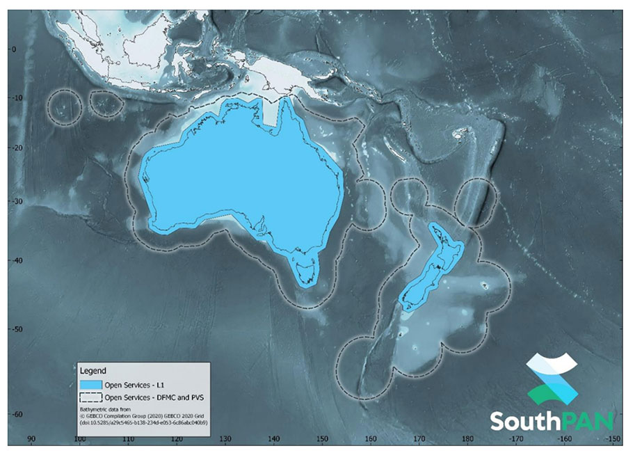
    Early Open Services

    SouthPAN will provide three early Open Services.

    L1 SBAS Open Service. The L1 SBAS early Open Service will provide navigation messages on the L1 frequency (1,575.42 MHz), and allow users with a receiver that tracks GPS L1 C/A signals to improve their position accuracy to better than ≤3m in the horizontal and ≤4 m in the vertical (95% confidence interval).

    DFMC SBAS Open Service. The Dual-Frequency Multi-Constellation SBAS early Open Service will provide navigation messages on the L5 frequency (1,176.45 MHz), and allow users — with a receiver that tracks GPS L1 C/A and L5 signals, and Galileo E1 and E5a signals — to improve their position accuracy to better than ≤1.5m in the horizontal and ≤2.5 m in the vertical (95% confidence interval).

    PVS Open Service. The Precise Point Positioning (PPP) via SouthPAN (PVS) early Open Service will share the L5 frequency with the DFMC SBAS Open Service in the near future, before transitioning to a new navigation signal. PVS will allow users — with a receiver that tracks GPS L1 C/A and L5 signals and Galileo E1 and E5a signals, and is capable of processing the PVS messages — to improve their position accuracy better than ≤0.40 m in the horizontal and ≤0.55 m in the vertical (95% confidence interval) after convergence. Convergence will be better than 80 minutes during PVS early Open Services, and the user does not need to remain stationary during the convergence period.

    SouthPAN early Open Services coverage. OS-L1 covers mainland Australia and New Zealand. OS-DFMC and OS-PVS cover Exclusive Economic Zones in both countries. (Image: Geosciences Australia)
    SouthPAN early Open Services coverage. OS-L1 covers mainland Australia and New Zealand. OS-DFMC and OS-PVS cover Exclusive Economic Zones in both countries. (Image: Geosciences Australia)

    More information is available in the SouthPAN Open Services factsheet for end-users and in the SouthPAN Service Definition Document (SDD) and Disclaimer.
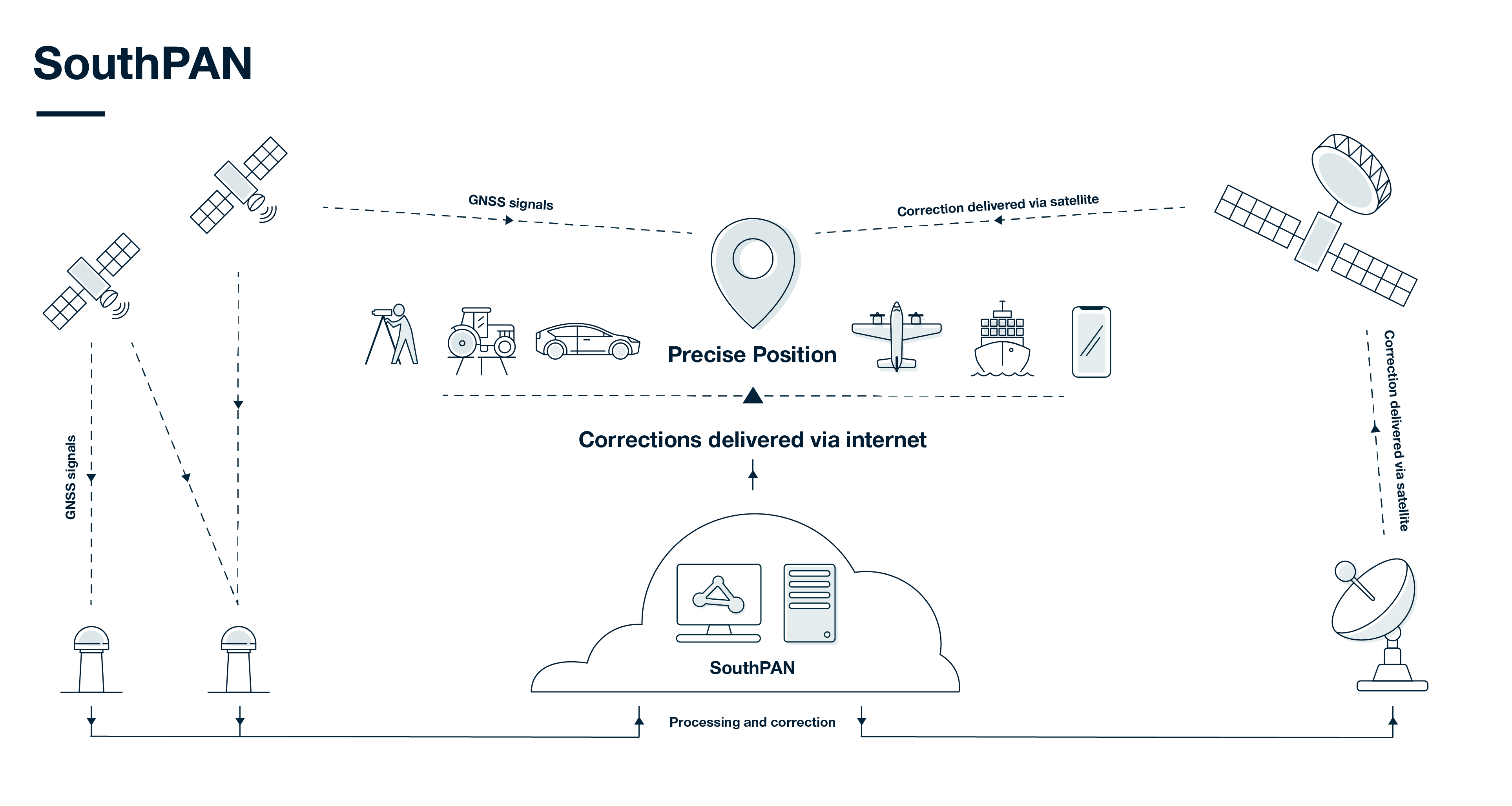
    How SouthPAN works

    SouthPAN uses several distributed ground stations to monitor signals broadcast by GNSS satellites, and compares each station’s known location with position data from the satellites.

    The GNSS signal data and measurement information is sent to correction processing facilities. The facilities aggregate the data from all ground stations, produce error corrections and status information about the GNSS satellites, and format the data in a standardized series of messages. These messages are sent to an uplink station, which transmits the data to a satellite in geostationary earth orbit. The data is broadcast to all precise positioning users, who combine SouthPAN’s data with their own observations of GNSS satellites.

    Image: Geosciences Australia
    Image: Geosciences Australia
  • U-blox and Geespace partner to extend positioning solutions to US, Europe

    U-blox and Geespace partner to extend positioning solutions to US, Europe

    U-blox and Geespace have signed a memorandum of understanding to expand their respective augmentation services for high-precision applications. Both partners will be able to extend their service offering to the U.S., European and Chinese markets, primarily in the automotive sector.

    Geespace is provider of aerospace information and communications (AICT) infrastructure and application solutions.

    The agreement between u-blox and Geespace seeks to create a combined offering that will enable both companies to offer full-stack high-precision positioning software and hardware solutions to customers across the United States, Europe and China. It will enable Geespace, which provides automotive GNSS augmentation services to its parent company Geely Group, to use the u-blox PointPerfect GNSS augmentation service to grow its coverage to serve Geely’s automotive brands.

    Meanwhile, it will enable u-blox to expand the coverage of the PointPerfect service to offer customers a comprehensive high-precision solution for products sold in China, and benefit from simplified development and logistics efforts.

    The rise of reliable and cost-effective high-precision positioning has improved the accuracy of GNSS solutions to the order of tens of centimeters, enabling new applications in the automotive, industrial and robotics industries. Global adoption has, however, been hampered by a fragmentation of the augmentation services landscape, the companies stated in a press release.

    For global adoption to become a reality, worldwide coverage is required, as is unified pricing and business models designed to serve mass-market high-precision solutions for automotive and industrial customers operating on a global scale, the companies said.

    Image: adamkaz/E+/Getty Images
    Image: adamkaz/E+/Getty Images
  • Next-generation EGNOS satellite orbited for GSA

    Next-generation EGNOS satellite orbited for GSA

    Image: GSA
    Image: GSA

    A Eutelsat communications satellite launched Oct. 9 carried a payload for the European GNSS Agency (GSA) called GEO-3. GEO-3 is a geostationary satellite designed to augment GNSS signals.

    The EGNOS payload, manufactured by Airbus Defence and Space, will hone the accuracy of satellite navigation signals over Europe for use in aviation, maritime and other industries as part of the European Geostationary Navigation Overlay System (EGNOS).

    The Eutelsat-5 West B satellite also hosts a payload that will enable service continuity for television broadcasting in Europe and North Africa.

    The GSA signed a contract in March 2017 with Eutelsat Communications for the development, integration and operation of the next-generation GEO-3 EGNOS payload.

    EGNOS operational messages are broadcast via navigation payloads on-board two GEO satellites, including an Inmarsat-3F2 satellite that is fast approaching end-of-life. The GEO-3 services replenish the EGNOS SBAS payloads, guaranteeing EGNOS availability and supporting the transition to the dual-frequency multi-constellation-capable EGNOS V3.

    Eutelsat will also develop two redundant RF ground stations to uplink the EGNOS message to the payload. It will also host EGNOS’ Navigation Land Earth Stations (NLES) in Rambouillet, France, and Cagliari, Italy, both of which will be co-located and connected to the RF ground stations.

    Proton-powered launch

    The satellite was carried aloft on a Proton rocket along with a second satellite, the Mission Extension Vehicle-1 for Northrop Grumman subsidiary SpaceLogistics, designed to service satellites. Both spacecraft were built by  Northrop Grumman.

    The Proton rocket lifted off at 6:18 a.m. Eastern Time from Russia’s Baikonur Cosmodrome in Kazakhstan. Its two passengers separated from the rocket 16 hours later in a supersynchronous transfer orbit.

    Eutelsat-5 West B is a replacement for the 17-year-old Eutelsat-5 West A satellite.

    artist's depiction, ILS/Loral
    SES-5 GEO satellite (Artist’s depiction: ESA).
  • Research Online: Navigation augmentation based on LEO communication satellite constellations

    Presented at ION International Technical Meeting 2018

    The main objective of this work is to investigation the feasibility and performances of LEO communication satellite constellations as potential navigation augmentation platforms. The further examination of the existing and upcoming LEO communication satellite constellations has been conducted, such as Iridium, Globalstar, Teledesic, One Web, Boeing, SpaceX, Samsung, etc. The comprehensive performances of LEOs for navigation augmentation are evaluated and analyzed in terms of constellation characteristics, footprint, coverage, signal strength, dilution of precision (DOP, including GDOP, PDOP, VDOP, HDOP), and number of in-view satellites, with comparison of these to the current GPS, Galileo and BeiDou systems. The results showed that LEOs present superior performances compared with GNSS systems, and demonstrate promises as navigation augmentation platforms for challenging environments.

    Moreover, the real-time signal-aided navigation method is explored, from user geometry and signal ranging errors to position errors. Then, we proposed a navigation system based on signals of opportunity from LEO platform. The proposed system relay on a terrestrial benchmark network consists of several monitoring stations with time synchronization. It would acquire the downlink communication signal from LEO platforms, and then estimate the time difference of arrival (TDOA) between stations with a correlation-based blind detection algorithm. The TDOA estimations and geographical position information are utilized to develop the time-delay-based spatio-temporal distribution model, which can determine the user’s position by matching the model with its estimated TDOA values. The proposed navigation system can operate stand-alone and facilitates the integration of communication and navigation system.

  • QZS-2 signal analysis, QZS-3 launched

    QZS-2 signal analysis, QZS-3 launched

    This month we bring you a guest column by Steffen Thoelert, André Hauschild, Peter Steigenberger and Oliver Montenbruck of the German Aerospace Center (DLR) and Richard B. Langley of the University of New Brunswick.


    UPDATE: Since Sept. 10, continuously operating DLR receivers in Sydney, Australia, and Chofu, Japan, have been reporting measurements from QZSS satellite J07, which, according to the QZSS Interface Control Document, is the geostationary satellite QZS-3.


    The second satellite of Japan’s Quasi-Zenith Satellite System (QZSS) has started transmitting navigation signals. QZS-2, or Michibiki-2, was launched on June 1, 2017, and joins its predecessor QZS-1 (Michibiki-1), which has been in orbit since September 2010.

    Both satellites have been placed into inclined geosynchronous, elliptical orbits, which enable extended satellite visibility periods over Japan and are characteristic features for this regional navigation system.

    The third satellite, QZS-3, was launched on Aug. 19, 2017, into a geostationary orbit. If all goes according to plan, a fourth satellite in an eccentric orbit will follow by the end of this year and complete the constellation.

    QZS-2 Signal Tracking

    It is not straightforward to tell when QZS-2 started signal transmission exactly. About four weeks after launch, on June 27 between 10:17 and 12:37 UTC, several Septentrio PolaRx GNSS receivers in the Asia-Pacific region recorded continuous L5 observations. About one week later, on July 4 shortly after 03:02 UTC, Javad and Trimble receivers picked up L1 C/A and L5 signals from QZS-2 for a few seconds. Then again, between 23:03 UTC on July 6, and 01:36 UTC on July 7, several receivers intermittently tracked the L1 C/A, L2C and L5 signals. Finally, on July 10, starting at approximately 01:03 UTC, these three signals were continuously tracked until approximately 04:00 UTC on July 12. Up until Aug. 1, signal tracking had remained intermittent, but has been stable since. This was presumably the result of interruptions in the signal transmission due to test activities.

    Figure 1. QZS-2 signals tracked by GNSS receivers in Chofu, Japan, (top plot) and Sydney, Australia, (bottom plot). The plots depict the measured C/N0 for L1 C/A (black), L2C (red) and L5 (green) together with the observed pseudorange (grey). The frequent discontinuities in the pseudorange are due to the receiver clock adjustments. Both receivers exhibited a short tracking outage at approximately 06:00 UTC. The interruption in tracking at Chofu around 08:00 UTC is due to the low elevation angle of the satellite.

    The plots in FIGURE 1 show QZS-2 signals as tracked by GNSS receivers in Japan and Australia on July 10. The two first sets of broadcast messages were transmitted on July 16 at 6:00 and 7:00 UTC. Regular transmission of broadcast ephemerides started on July 27 at 22:00 UTC, but deviations from the hourly update rate still occur from time to time.

    Identical or Fraternal Twins?

    At first glance, QZS-2 seems like a look-alike of QZS-1, but there are many differences between the two spacecraft. Most apparent is the presence of an additional auxiliary antenna. Like QZS-1, QZS-2 transmits its navigation signals on the L1, L2, L5 and L-band Experiment (LEX) frequencies through the main antenna, while the augmentation signal L1S (formally known as Submeter-class Augmentation with Integrity Function or SAIF) is transmitted from a separate antenna. However, the new L5S signal, which is introduced with QZS-2, is transmitted with yet another antenna.

    The new satellite also has a shorter “wingspan” of only 19 meters, since it is equipped with two solar panel segments on each side, compared to three segments for QZS-1 with a width of 25.3 meters. The second QZSS satellite also follows a different attitude model: Unlike QZS-1, which switches between yaw-steering mode and orbit-normal mode depending on the sun’s elevation angle with respect to the orbit plane, QZS-2 always remains yaw-steering except for short periods of time when orbit maneuvers are performed. Further differences will become apparent in the analysis of the signal spectra in the subsequent sections.

    The Cabinet Office of the Government of Japan, which oversees QZSS as a national undertaking, has published QZSS satellite metadata information on its official website. At the time of writing, only one document for QZS-2 is available, which contains information about the satellite’s properties such as mass, dimension, attitude law and reference frame, but also antenna and laser retroreflector positions, antenna phase-center offsets and variations as well as signal group delays.

    Additional documents containing metadata for QZS-1, -3 and -4 and further information about QZS-2 are in preparation.

    Rubidium Clock

    FIGURE 2 illustrates the stability of the QZS-2 rubidium atomic frequency standard (RAFS) by means of the Allan deviation (ADEV). Data from a global network of 150 GNSS stations was processed to estimate GPS and QZSS satellite orbit and clock parameters.

    Figure 2. Allan deviation of the rubidium atomic frequency standards of GPS Block IIF satellite G32, QZS-1 (J01) and QZS-2 (J02).

    However, whereas about 60 of these stations provide QZS-1 observations, QZS-2 is only tracked by 13 stations. ADEV values for QZS-1, QZS-2 and a GPS Block IIF satellite were computed from a daily solution for Aug. 3 with 30-second clock sampling.

    At an integration time of 100 seconds, the QZS RAFS reaches an ADEV of better than 3 × 10-13.

    At longer integration times, the QZS-2 clock almost reaches the stability of the GPS Block IIF RAFS.

    Based on this preliminary analysis for only one day, the QZS-2 clock seems to perform as expected. The larger ADEV values compared to QZS-1 for integration times up to 1,000 seconds might be attributed to the significantly smaller number of tracking stations contributing to the QZS-2 clock solution. The quality of the clock solution will improve as soon as more stations are able to track QZS-2.

    Signals with High-Gain Antenna

    Complementary to the receiver measurements and analysis, the German Aerospace Center (DLR) has also recorded raw spectral and in-phase and quadrature (IQ) data of QZS-2 to get further insights into the transmitted signal structure and initial signal quality. FIGURE 3 shows a spectral measurement of the complete GNSS L-band frequency range, which shows the signal transmissions of QZS-2 in the L1, L2, L5 and L6 bands. The signal was captured with DLR’s 30-meter high-gain antenna at Weilheim, southwest of Munich, operated by DLR’s German Space Operations Center.

    Figure 3. QSZ-2 L-band normalized power spectra recorded at Weilheim, Germany, on July 18, 2017 at 20:43 UTC.

    This first view of the signal transmission shows a good spectral shape, appropriate band filtering and no out-of-band unwanted spurious emissions of the satellite. For further analysis, we looked closer at each signal-band spectrum and performed IQ-sample recording.

    Comparing the QZS-2 spectra to that of QZS-1, we see differences in the signal structure for the L1 frequency band.

    Figure 4. QZS-1 and QZS-2 L1 spectral flux density.

    FIGURE 4 shows the L1 spectra of both satellites. The additional signal component can be seen at an offset of 6 x 1.023 MHz and 18 x 1.023 MHz from the L1 center frequency of 1575.42 MHz. This is the result of the new L1C-pilot modulation, which is based on the time-multiplexed binary offset carrier (TMBOC) modulation technique using a mixture of BOC(1,1) and BOC(6,1). See here for detailed information.

    Another difference is present in the L6 band and can be seen within the signal time domain or the IQ domain. The new satellite transmits two components (one each for the I- and Q-channels) while QZS-1 transmits only one I-component. This observation is fully in line with the QZSS Interface Specification. On QSZ-2, an additional L6 signal component (Centimeter-Level Augmentation Message for Experiments, L6E) is implemented. FIGURE 5 shows the IQ constellation plots of QZS-1 and QZS-2 for the L6 band.

    Furthermore, the L5 band IQ plot of QZS-2 exhibits significant differences compared to QZS-1. These differences, which are illustrated in the plots of FIGURE 6, are due to an additional L5S signal transmitted by QZS-2.

    The QZS-2 L5 IQ diagram is fairly easy to understand as a coherent superposition of two distinct quadrature signals from two antennas. One signal is the GPS-like L5 signal transmitted from the main L-band antenna, while the other (L5S) signal originates from a new L5S antenna. This is illustrated in FIGURE 7.

    Figure 7. QZS-2 L5 IQ constellation plot including demarcation of the L5 and L5S signals.

    For illustration purposes, the dashed orange square in Figure 7 relates to the 10 MHz L5 signal, while the smaller red squares are the 10 MHz L5S signal.

    A code generator has been setup according the QZSS L5 and L5S interface control document (ICD). An analysis of the correlations of possible pseudorandom noise (PRN) codes resulted in the detection of PRN 194 and PRN 196. Based on the information in the ICDs, PRN 194 is used for L5 and PRN 196 is used for L5S.

    The performed code correlation analysis also yields the finding that the L5 signal is approximately 3.5 dB stronger than the L5S signal. Note, however, that both signals have a specified minimum receive power of -157 dBW. Due to the limited visibility of QZSS satellites from the Weilheim ground station, it is not possible to verify this value.

    Conclusion

    With the launch and activation of QZS–2, the deployment of Japan’s regional navigation system is moving forward again. The launch of a geostationary satellite, QZS-3, took place on Aug. 18. A fourth Japanese navigation satellite is scheduled to launch later this year. With this rapid  sequence, the target date of 2018 for the completion of an operational constellation with four satellites is quite realistic.


    Steffen Thoelert, André Hauschild, Peter Steigenberger and Oliver Montenbruck are from the German Aerospace Center (DLR).

    Richard B. Langley is from the University of New Brunswick and authors the monthly Innovation column for GPS World magazine.

  • Thales signs contract to upgrade Europe’s EGNOS

    Thales signs contract to upgrade Europe’s EGNOS

    The European Space Agency (ESA) has signed a contract with Thales Alenia Space for an upgrade to Europe’s EGNOS satellite navigation augmentation system, which underpins the safety-critical use of satnav across Europe, according to ESA.

    Designed by ESA and being exploited by Europe’s GNSS Agency (GSA), the European Geostationary Navigation Overlay Service (EGNOS) improves the precision of GPS signals over most European territory, while also providing continuous and reliable updates on the “integrity” of these GPS signals.

    A network of ground monitoring stations throughout Europe performs an independent measurement of GPS signals, so that corrections can be calculated, and then passed to users immediately via a trio of geostationary satellites.

    The result is that the EGNOS-augmented signals are guaranteed to meet the extremely high performance standards set out by the International Civil Aviation Organisation standard, adapted for Europe by Eurocontrol, the European Organisation for the Safety of Air Navigation.

    Paul Verhoef, ESA director of the Galileo Program, and Philippe Blatt, VP Thales Alenia Space France, sign on June 6 a contract for an upgrade of EGNOS.

    Paul Verhoef, ESA’s director of the Galileo programme and navigation-related activities, signed the contract at ESA Headquarters in Paris with Philippe Blatt, vice president of Thales Alenia Space France.

    ESA is performing the procurement of EGNOS Version 2.4.2 under the overall program authority of the GSA, which oversees both EGNOS and Europe’s Galileo satellite navigation system.

    Two upgraded EGNOS releases will be provided over the course of the development: EGNOS V2.4.2I and EGNOS V2.4.2A.

    The releases will resolve various obsolescence issues related to EGNOS’s central processing facility, based in Toulouse, France — which generates the corrections and integrity information to be broadcast across the European continent — to ensure continuity of EGNOS services into the future, including safety-of-life services, to an ever-expanding community of users.

    The new contract includes:

    • a refreshment and enhancement of the Central Processing Facility design without algorithm modification
    • an optimized qualification process
    • a guarantee of full compliance to safety-critical software development requirements
    • the performance of end-to-end verification activities extending to the three geostationary satellites used by the system
    • ensuring compliance to a new set of technical requirements and international standards.

    Below is a video about EGNOS.

  • Upgrades to monitoring stations support EGNOS

    Upgrades to monitoring stations support EGNOS

    Upgrades to the monitoring stations underpinning Europe’s EGNOS satnav augmentation system will support its evolution, said the European Space Agency.

    The current 40 Ranging and Integrity Monitoring Stations (RIMS) sites across Europe and beyond are the bedrock of the European Geostationary Navigation Overlay Service (EGNOS), supplying highly accurate and robust satnav information that can be relied on for safety-critical purposes.

    Thales EGNOS V3 RIMS rack.

    Once a second, these stations gather raw satnav data to transmit information on signal quality and range measurements to the GPS satellites, allowing EGNOS to identify and remove any error in the signals.

    The resulting corrections are then passed to users via a trio of geostationary satellites, delivering a several-fold increase in precision plus “integrity” — a guarantee of navigation service — for safety-of-life applications.

    The result is that the EGNOS-augmented signals are guaranteed to meet the extremely high performance standards set out by the International Civil Aviation Organisation standard, adapted for Europe by Eurocontrol, the European Organisation for the Safety of Air Navigation.

    The signals from space can therefore be relied on routinely for safety-critical tasks, such as vertically guiding aircraft during landing approaches.

    “These current RIMS V2 stations have some inherent limitations, which we’ve sought to tackle in this upgraded V3 design,” said Didier Flament, ESA’s EGNOS programme manager.

    Airbus EGNOS V3 RIMS rack.

    “For instance, our current stations work only with GPS frequencies L1/L2 P(Y), while the future post-2020 EGNOS system will be operating on a multi-constellation basis, additionally employing modernized GPS signals, notably on both the L2 (L2C) and L5 frequency bands, as well as other signals from Galileo, on the similar E1 and E5 frequency bands.

    “Our experience working with RIMS has emphasized the significance on performance of factors such as signal scintillation — caused by the ever-changing ionosphere, the electrically active layer of the upper atmosphere — as well as other environmental threats such as interference and multipath signal reflection.

    “So this upgraded design increased robustness to these factors, based on more stringent development and operating standards, along with innovative radio-frequency environment monitoring.

    “It also includes upgraded receiver technology to accurately monitor potential GPS and Galileo signal distortion — ‘evil waveform’ signal anomalies — in full compliance with international standards.”

    The RIMS V3 stations will be based in the same or similar secure location as today’s stations — typically airports or space-based telecommunication sites.

    Dual tracking antenna concept incorporated in EGNOS V3 RIMS design.

    The individual RIMS antennas themselves can be relatively compact, about 50 cm high, with links to receiver and computing equipment.

    Most of the RIMS V2 station antennas are currently surrounded by dedicated protection structures that limit the impact of interference and multipath local effects.

  • Satnav Augmentation Systems Settle on Common Channels Post-2020

    Satnav Augmentation Systems Settle on Common Channels Post-2020

    EGNOS is Europe’s first venture into satellite navigation. EGNOS broadcasts augmented information through a trio of geostationary satellites linked to a network of monitoring ground stations, to sharpen the accuracy and reliability of GPS signals across the continent.
    EGNOS is Europe’s first venture into satellite navigation. EGNOS broadcasts augmented information through a trio of geostationary satellites linked to a network of monitoring ground stations, to sharpen the accuracy and reliability of GPS signals across the continent. (artist’s concept: ESA)

    News from the European Space Agency

    The next decade’s aircraft pilots will be able to rely on enhanced, reliable satellite navigation signals on a seamless basis across much of the world, thanks to decisions made at the latest gathering of worldwide satnav augmentation system providers and experts.

    The U.S. Wide Area Augmentation System (WAAS) and European Geostationary Navigation Overlay Service (EGNOS) are leading examples of satellite-based augmentation systems (SBAS) that apply additional ground stations and satellite transponders to sharpen the accuracy and reliability of existing satnav services across given geographical regions.

    These performance enhancements permit satnav to be employed for safety-of-life services, especially aviation. Such systems are based on the U.S. GPS for now, but plans are being laid to move to a multi-constellation design employing Europe’s Galileo, China’s Beidou and Russia’s GLONASS satnav systems beyond 2020.

    The 28th Satellite-based Augmentation Systems Interoperability Working Group (IWG), planning standardization of SBAS systems to come, was hosted at ESA’s ESTEC technical centre at Noordwijk, the Netherlands, on April 1-3.

    The ESTEC facility in Noordwijk, The Netherlands.
    The ESTEC facility in Noordwijk, The Netherlands. (Photo: ESA)

    All participants unanimously endorsed the “message definition” for a new secondary SBAS channel — to be known as L5, along with the current L1 — for the planned second-generation SBAS systems, which will utilize dual-frequency multi-constellation signals.

    Using dual frequencies greatly increases the accuracy of navigation systems, by allowing interference from the ionosphere — an electrically active outer layer of Earth’s atmosphere — to be largely subtracted from the final result.

    “This definition is presented in what is called the Dual Frequency Multi-Constellation Definition document,” explained Didier Flament, representing ESA. “It represents the outcome of a four-year activity, which started at IWG 19 in Japan, back in 2010, coordinated between all IWG members under the technical leadership of ESA and French space agency CNES on the European side, and the Federal Aviation Authority (FAA) and Stanford University on the U.S. side.

    “The formal IWG review loop for the document took six months to conclude, with this IWG 28 then allowing endorsements to be gathered by SBAS project managers, culminating in formal signatures to the document,” Flament said.

    Planned_SBAS_coverage_for_2020-W
    SBAS coverage for 2020: Comparing current worldwide SBAS coverage — based on WAAS, EGNOS and MSAS — to the situation envisaged for 2020–25: near-global coverage based on WAAS, EGNOS, MAAS, SDCM and GAGAN, with an expanded network of stations in the southern hemisphere, all based on a common dual-frequency/dual satnav standard being finalized by the SBAS Interoperability Working Group. (Image: ESA)

    IWG members now intend to have this document accepted by the official international SBAS standardization bodies: the International Civil Aviation Organisation, the U.S. Radio Technical Commission for Aeronautics (RTCA) and the European Organisation for Civil Aviation Equipment.

    “This next step is very important,” added Didier. “Not only for the coming 2016-22 implementation of the European EGNOS v3 but for implementation of other second generation SBAS in other regions of the world.”

    The meeting also reported on the state of development of the other global SBAS systems. Along with the four operational systems — the U.S. WAAS, European EGNOS, Japan’s Multi-functional Satellite Augmentation System (MSAS) and India’s GPS-aided geo-augmented navigation or GPS and geo-augmented navigation system (GAGAN) — these comprise South Korea’s KASS, China’s Beidou SBAS, Russia’s System for Differential Corrections and Monitoring (SDCM) and the West African Agency for Aerial Navigation Safety in Africa and Madagascar (ASECNA) SBAS.

    The follow-up IWG meeting will take place in October, hosted by the FAA in Washington, D.C., in conjunction with the next RTCA meeting.

  • IRNSS-1D Reaches Orbital Slot

    IRNSS-1D Reaches Orbital Slot

    Photo: IRNSS-1D

    News courtesy of CANSPACE Listserv.

    The fourth satellite in the Indian Regional Navigation Satellite System, launched on March 28, has arrived at its designated orbital slot.

    Based on data supplied by the U.S. Joint Space Operations Center, IRNSS-1D is in an inclined geosynchronous orbit with an inclination of 30.5 degrees and a nodal longitude of 111.7 degrees east, within the allowed limits of the assigned longitude of 111.5 degrees east.

  • UK Space Agency Awards SBAS Africa Contract to Avanti

    Avanti Communications has been appointed by the UK Space Agency to deliver a crucial air navigation project in Africa, SBAS-AFRICA. The satellite operator has been awarded the contract under the agency’s International Partnership Space Programme (IPSP), which exists to open up opportunities for the UK space sector to share expertise in real-world satellite technology and services overseas.

    Africa has just 3 percent of global air traffic, and yet air accidents in Africa account for roughly 20 percent of the worldwide total. By demonstrating potential improvements in flight safety via SBAS technologies, the project can provide socio-economic benefits to the continent, according to a news release from Avanti.

    Based on prior cost-benefit modeling which identified a €1.7 billion potential economic benefit to the African aviation sector from the deployment of SBAS services, SBAS-AFRICA will help accelerate the adoption of GNSS-based flight operations, positively influence the evolution of aviation safety in Africa and encourage development in the wider African economy.

    SBAS-AFRICA will deliver a satellite-based augmentation system for GNSS-based operations in the aviation sector, serving significant parts of Africa in partnership with a number of local stakeholders. The project will use a unique asset, Avanti’s ARTEMIS L1 Navigation transponder, to provide a navigation data broadcast service.

    SBAS-AFRICA brings an innovative and pragmatic approach to deploying SBAS services in Africa,” said Matthew O’Connor, Chief Operating Officer at Avanti Communications. “It establishes crucial collaboration between the UK and a number of African countries, including South Africa and Ghana. Participating countries will benefit hugely from expertise gained, placing them at the forefront of navigation services across the continent and, crucially, helping to improve aviation safety for a major generator of economic benefit in Africa.”

    He continued, “The Artemis satellite will play an integral role in this project. We expect that such a showcase for its performance, accuracy and quality will provide further evidence of what can be achieved with this technology and lead to significant commercial opportunities.”

    “The UK Space Agency is delighted to play a role in fostering new international partnerships that not only enable innovative UK space companies like Avanti to provide more high-tech exports that can boost our space sector but also allow the UK to widely share the considerable social and economic benefits that space technology and infrastructure can provide,” said David Parker, chief executive of the UK Space Agency.

  • India’s IRNSS-1D Launched into Orbit

    India’s IRNSS-1D Launched into Orbit

    IRNSS-1D-1-launch
    Photo credit: ISRO

    The fourth satellite of IRNSS satellite navigation constellation, IRNSS-1D, was launched onboard PSLV-C27 on Saturday, March 28, according to the Indian Space Research Organization (ISRO). The Polar Satellite Launch Vehicle blasted off at 11:49 GMT (7:49 a.m. EST), or 5:19 p.m. local time, at the Satish Dhawan Space Center on India’s east coast.

    This is the fourth successful launch of a navigation satellite in less than a week, following GPS IIF-9 on Wednesday and Galileo 7 and 8 on Friday. A fifth navigation satellite, for the BeiDou constellation, is expected to launch tomorrow.

    This is the 28th consecutively successful mission of the PSLV, the ISRO said. The “XL” configuration of PSLV was used for this mission. Previously, the same configuration of the vehicle was successfully used seven times.

    After the PSLV-C27 lift-off with the ignition of the first stage, the subsequent important flight events took place as planned. After a flight of about 19 minutes, 25 seconds, the IRNSS-1D satellite was injected to an elliptical orbit of  282.52 km X 20,644 km, very close to the intended orbit, and successfully separated  from the PSLV fourth stage.

    After injection, the solar panels of IRNSS-1D were deployed automatically. ISRO’s Master Control Facility (at Hassan, Karnataka) took over the control of the satellite. In the coming days, four orbit maneuvers will be conducted from the Master Control Facility to position the satellite in geosynchronous orbit at 111.75 degrees East longitude with 30.5 degrees inclination.

    IRNSS-D is the fourth of seven IRNSS satellites to be launched to provide navigational services to the region, according to the ISRO. The satellite was placed in geosynchronous orbit. Predecessors IRNSS-1A, 1B and 1C were launched by PSLV-C22, PSLV-C24 and PSLV-C26 in July 2013, April 2014 and October 2014 respectively. All the satellites are functioning satisfactorily from their designated orbital positions.

    The IRNSS navigational system is regional, and targeted towards South Asia. The satellite will enable navigation, tracking and mapping services.

    The next satellite, IRNSS-1E, is scheduled to be launched by PSLV. The entire IRNSS constellation of seven satellites is planned to be completed by 2016.

    IRNSS-1D-2-launch
    Photo credit: ISRO
    IRNSS-1D-3-launch
    Photo credit: ISRO
  • Launch of IRNSS-1D Now Set for Saturday

    The launch of India’s fourth Navigation Satellite, IRNSS-1D, is now scheduled for 17:19 IST (11:49 UTC) on Saturday, March 28, from Satish Dhawan Space Centre, Sriharikota.

    The launch was previously scheduled for March 9, then postponed until March 29 to replace a faulty telemetry transmitter on the satellite, according to the Indian Space Research Organization.

    IRNSS-1D will be fourth in the seven-spacecraft Indian Regional Navigation Satellite System constellation. It will be flown into space in the Indian Polar Satellite Launch Vehicle-XL.

    The space segment of the IRNSS consists of seven satellites: three  in geostationary orbit and four in inclined geosynchronous orbit. The ground segment consists of infrastructure for controlling, tracking and other facilities. The entire IRNSS constellation of seven satellites is planned to be completed by 2015.

    Both IRNSS-1A and 1B are functioning satisfactorily from their designated geosynchronous orbital positions. The first three satellites in the IRNSS series were launched from Sriharikota on July 1, 2013, April 4, 2014, and October 16, 2014. IRNSS-1E and IRNSS-1F satellites are expected to be launched before year end.

    IRNSS is an independent regional navigation satellite system designed to provide position information in the Indian region and 1,500 kilometers around the Indian mainland. IRNSS will provide two types of service: Standard Positioning Services (SPS) — provided to all users — and Restricted Services (RS), provided to authorized users.