Common sense tells us not to hold a smartphone while driving. But a new game is so addicting, it’s causing people to forget that rule.
Released July 6 for both Android and iOS, Pokémon GO instantly became the top free app and the top grossing app on Apple’s App Store, shattering social media records and shooting Nintendo stock through the roof. And it hasn’t even been introduced in Europe and Asia yet. (Japan, of course, is the birthplace of Pokémon.)
The game uses augmented reality to place the coveted virtual monsters (Pokémon) into real-world locations, so users have to travel to add to their collections.
However, much like in the early days of GPS navigation, when people ended up driving down railroad tracks or into ponds, the Pokémon GO app has led to accidents. Some users are playing the location-based game from inside their vehicles, stopping suddenly, while pedestrians are staring at device screens as they walk through busy cities, sometimes onto private property.
In the first week:
A 28-year-old Auburn, New York, driver ran his vehicle off the road and crashed into a tree.
A Massachusetts man woke up to a garden full of wandering Pokémon players after his home — once a church — had been marked as a “gym” (multi-player battleground).
A group of Missouri teenagers were arrested for armed robbery after allegedly using the app to anticipate secluded locations for holdups.
Police departments around the country are warning that anyone caught using the app while driving or jaywalking could end up with a hefty fine.
But there’s an upside, too. Gamers are going outside, getting exercise and making new social connections.
And, apparently, helping police. One 19-year-old Wyoming woman, on a quest to catch a Pokémon from a natural water resource, instead discovered a dead body floating in the Big Wind River.
Nintendo has launched a beta test of a new Pokémon game that takes place in the real world. The beta testing began July 6.
Using Pokémon GO, gamers travel between the real world and the virtual world of Pokémon with iPhone and Android devices.
Pokémon GO is built on Niantic’s Real World Gaming Platform for augmented reality. It uses GPS to encourage players to search far and wide in the real world to discover Pokémon. The game allows players to find and catch more than a hundred species of Pokémon as they explore their surroundings.
Players are represented on an augmented reality map of the real world.
Moving around, the smartphone vibrates when near a Pokémon. When players encounter a Pokémon, they take aim on their smartphone’s touchscreen and throw a Poké Ball to catch it. the player is indicated on a map showing their actual location.
The game encourages users to explore the cities and towns where they live to capture as many Pokémon as they can. Also, PokéStops are located at interesting places, such as public art installations, historical markers and monuments, where players can collect more Poké Balls and other items.
Players can also join teams, and “battle” with their captured Pokémon at “gyms” that can be found at real-world locations.
The Pokémon GO Plus wearable can be removed from the band and worn on a shirt.
The Pokémon video game series has used real-world locations such as the Hokkaido and Kanto regions of Japan, New York, and Paris as inspiration for the fantasy settings in which its games take place. This is the first time the popular game franchise has used the real world as its setting.
While the game is free to play, Nintendo will be rolling out a $35 wearable that enables play without looking at a smartphone, such as for joggers on their morning run.
Bosch Sensortec is unveiling new generations of intelligent accelerometers and high-performance gyroscopes at the 2016 International CES in Las Vegas.
Aimed at smartphones, tablets and wearables, the new devices cover a wide range of requirements, from low-power consumption for always-on applications such as step counting, to high-performance optical image stabilization (OIS).
Intelligent three-axis accelerometers — BMA422 and BMA455
Today’s applications running on modern mobile devices place many demands on motion sensors. These sensors are required to continuously sense motion, such as for step counting operations, while at the same time delivering a high level of performance without compromising battery lifetime.
To meet these challenges, the new sensors from Bosch Sensortec integrate embedded intelligence functionality into standalone accelerometers. Adding intelligent features to an accelerometer enables innovative applications, while minimizing power consumption by eliminating the need to wake up an application processor or an additional discrete sensor hub. Overall system power management and user experience can be improved by the accelerometer detecting and processing motions such as glance, pick-up and tilt.
Current consumption of the new accelerometers is kept very low to extend battery life. The integrated Android 6.0 “Marshmallow” features minimize programming effort for customers. Each device delivers outstanding accelerometer performance for low offset, low temperature coefficient offset (TCO) and low noise levels, the company said.
Two new accelerometers are being launched: the BMA422 “all-rounder” is suitable for standard applications, and the BMA455 provides high performance for gaming and immersive activity tracking. In addition, the high level of performance enables demanding applications covering augmented reality, virtual reality, image stabilization and industrial measurement applications such as spirit leveling and inclination measurement.
High-performance gyroscopes — BMG250 and BMG280
Mobile devices require gyroscopes for many applications, including gaming, augmented reality, virtual reality and OIS. To provide the necessary performance, Bosch Sensortec’s new gyroscopes combine the most important parameters in a single device: low noise, low TCO and high bias stability.
Although delivering high performance, they do both feature the lowest power consumption of any standalone gyroscope in the market, thus helping to extend battery lifetime in mobile devices.
Today’s announcement includes two three-axis gyroscopes: the BMG250 provides low noise, low TCO and high bias stability, while the BMG280 delivers ultra-low noise optimized for OIS and includes a secondary interface for OIS, making it fit for use in camera modules. The BMG280’s secondary interface can be used in parallel with the primary user application interface, for example for simultaneous panorama creation and OIS.
Packages and availability
The new devices are provided in small packages. The BMA422 measures 2.0 x 2.0 x 0.95 mm³, while the BMA455 is 2.0 x 2.0 x 0.65 mm³. The BMG250 and BMG280 gyroscopes both measure 3.0 x 2.5 x 0.83 mm³.
Samples of the all sensors are available now, with mass production of the gyroscopes to commence in Q1 2016 and mass production of the accelerometers starting in mid-2016. For pricing, contact Bosch Sensortec.
Swiss startup WayRay has introduced an augmented reality navigation system that projects holographic GPS imagery and driver notifications onto the windshield of a car.
Navion, billed as the “first-ever holographic navigation system for cars,” is placed on a car’s dashboard and projects a virtual route into the regular focal range of the driver. The driver sees the navigation signs laid out directly on the road ahead of the moving vehicle, while the driver’s eyes are safely focused on the road at all times. “We call this concept natural navigation, and we believe it will change the way we drive,” WayRay said in a press release.
In contrast to other augmented reality devices currently on the market, no additional eyewear or headgear is needed to see the image. Navion’s interface provides the driver with clear route indicators even in bright sunlight, the company said.
Navion responds to simple hand gestures and voice control. Certain features are available for use only when the car is stopped or moving at a very low speed.
WayRay is a Swiss-based innovator working with augmented reality technology to develop holographic navigation systems and advance the connected car. The WayRay story goes back to 2012, when Founder and CEO Vitaly Ponomarev had an unexpected experience.
“I was living in Moscow at the time, and I was driving at a low speed while also trying to adjust my brand-new GPS,” Ponomarev said. “My attention got distracted just for an instant and I had my first-ever car accident. The accident had a profound effect on me and I began to think about how the windshield is the perfect place to start when it comes to improving car safety. That began this remarkable journey and inspired the creation of WayRay.”
In its two years of development, the company has emerged as a premier developer in connected cars by applying aerospace technology to land navigation — the principles behind its two key products.
The company first developed the WayRay Element, a smart car tracker that collects data from the car and transforms it into statistics about the driver. Element works in conjunction with the WayRay Navion. Both products are to be released in 2016.
“I think WayRay is the step between where we are now and the future self-driving car that is connected to a city’s infrastructure,” Ponomarev said.
WayRay is headquartered in Switzerland with offices in Moscow and San Francisco.
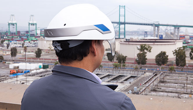
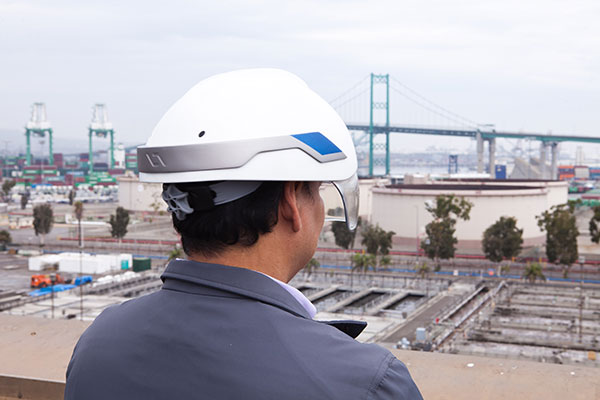
Topcon Positioning Group is collaborating with DAQRI, an augmented reality company, on wearable technology designed to change the way construction and survey professionals interface with the job site.
DAQRI is the creator of the DAQRI Smart Helmet, an industrial-grade wearable that seamlessly connects humans to their work environments by providing information about the world around them.
Topcon and DAQRI will work together to create a solution designed to make workers on the job safer and more productive through the use of augmented reality technologies. They plan to do this by integrating DAQRI’s hardware and software solutions with Topcon positioning solutions.
The DAQRI Smart Helmet was designed for the industrial workplace. It includes an advanced sensor package, an intuitive user interface that requires zero calibration, and a battery that lasts a full shift.
Powered by 4D Studio, DAQRI’s software platform for positioning, the partnership will allow construction workers to view information from their projects in the real-world work environment to make their workflows safer and more efficient.
The collaboration is designed to bring wearable technology to a wider AEC (architecture, engineering and construction) user base, empowering the wearer with a hands-free tool that can be used on the job, Topcon said in a news release.
“DAQRI is a leader in providing solutions in outdoor environments, which will meld well with our positioning and software innovations,” said Jason Hallett, Topcon vice president of product management. “It’s the first step in utilizing our mutual synergies to develop rugged, heads-up display technology for our marketplace.”
“We are committed to developing innovative solutions that power the future of work and Topcon is at the forefront of the industry with some of the most innovative products that are being used by millions of workers across a variety of environments,” said Matt Kammerait, vice president of product, DAQRI. “This makes them the perfect partner to integrate the Smart Helmet into existing workflows. We look forward to seeing how our partnership re-defines the nature of ‘work,’ by setting a new standard for wearables in the AEC space.”
The first Gen III F-35 Helmet Mounted Display System has been delivered. (Photo: Rockwell Collins)
Lockheed Martin and Rockwell Collins have delivered the first Gen III F-35 Helmet Mounted Display System (HMDS). The advanced technology for warfighters provides pilots with unprecedented levels of situational awareness and allows them to “look through” the airframe.
Company executives commemorated the delivery of the first HDMS on Aug. 11 with Sen. Joni Ernst in Cedar Rapids, Iowa. In addition to the HMDS, the Lockheed Martin F-35 Lightning II demonstrator was on site at the Cedar Rapids headquarters of Rockwell Collins for Sen. Ernst to get a first-hand experience of “flying” the military’s most advanced fighter jet following the delivery ceremony.
Rockwell Collins, through its joint venture, Rockwell Collins ESA Vision Systems LLC, is providing the most advanced technology for warfighters with the F-35 HMDS, which provides pilots with unprecedented levels of situational awareness and allows them to “look through” the airframe.
The Gen III helmet, which includes an improved night vision camera, improved liquid-crystal displays, automated alignment and software improvements is to be introduced to the fleet in low rate initial production Lot 7 in 2016. Rockwell Collins ESA Vision Systems LLC also developed the Gen II helmet that F-35 pilots currently use, which met the needs for the U.S. Marine Corps and will allow the service to declare Initial Operational Capability.
All the information that pilots need to complete their missions — through all weather, day or night — is projected on the helmet’s visor. Additionally, the F-35’s Distributed Aperture System (DAS), made by Northrop Grumman, streams real-time imagery from six infrared cameras mounted around the aircraft to the helmet, allowing pilots to “look through” the airframe.
“Today’s visit was an opportunity to place focus on Rockwell Collins, as manufacturing makes up such an important part of our economy here in Iowa,” said Senator Ernst. “Having served in the military for over 20 years, I appreciate the company’s efforts in support of our national defense, our armed forces and our veterans.”
“We’re pleased to be able to demonstrate the advanced capabilities of the F-35 Lightning II at Rockwell Collins today to Sen. Ernst and members of the Cedar Rapids community,” said Steve Callaghan, director, F-35 Program, Lockheed Martin Washington Operations. “The employees at Rockwell Collins are contributing to the F-35s flying today, and we’re pleased to have the opportunity to showcase the superior performance capabilities of this aircraft with them.”
Overall, Rockwell Collins has built and fit more than 200 helmets for F-35 pilots who are being trained for the program.
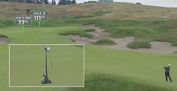
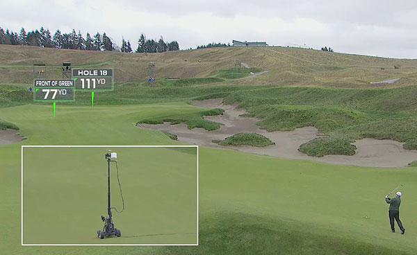
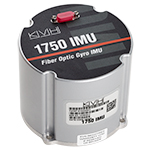
Golf fans who watched televised coverage of the U.S. Open golf tournament June 18-21 got a new outlook on what the professional golfer is facing, thanks to a camera and augmented-reality tracking system that includes a 1750 inertial measurement unit (IMU) from KVH Industries.
Called RangeFinder, the system was developed by Sportvision, Inc., creators of football’s Virtual Yellow 1st and Ten Line, in conjunction with FOX Sports, and it debuted during the broadcast of the 115th U.S. Open from Chambers Bay, in University Place, Wash.
The KVH 1750 IMU,
At the heart of Sportvision’s RangeFinder system is a broadcast-quality camera with a KVH 1750 IMU mounted in a box at the top of the camera; the IMU works in conjunction with a GPS mounted at the base of the camera. By combining data from the IMU and the GPS, the RangeFinder system enables the measurement of the precise location and attitude of the camera; with that information, Sportvision technicians create augmented-reality graphics that indicate how far away a green, sand trap, obstacle or any other feature is located.
“We selected KVH’s 1750 IMU due to its performance attributes, its size and weight, as well as its cost-effectiveness,” said Mike Jakob, Sportvision president and chief financial officer. “We know this IMU well for what it brings to some of our other products, and we appreciate the reliability and high quality.”
KVH’s 1750 IMU incorporates three axes of KVH’s DSP-1750, a tiny fiber optic gyro, with three axes of accelerometer technology to create an advanced six-degrees-of-freedom sensor. Designed to integrate easily into demanding stabilization, pointing and navigation applications, the 1750 IMU enhances performance at a lower cost than competing systems, KVH said.
“Our IMUs and other inertial sensors have been used in several of Sportvision’s innovative products, including the LiveLine system for America’s Cup yacht racing coverage, and we are thrilled to play a role in this new system for golf coverage,” said Martin Kits van Heyningen, KVH chief executive officer.
The RangeFinder system is designed to enhance the television viewer’s enjoyment of golf competitions by providing more insight into the setting. “The camera is mounted on a mobile tower that can go vertical 20 feet in the air, and that gives the viewer a really unique perspective of the course,” said Ken Milnes, project manager for Sportvision. “With the camera fully instrumented, we can put augmented-reality graphics on the TV screen. We virtually insert a rectangular placard that the TV viewer sees, with a pointer arrow and the yardage to the hole or obstacle.”
During the U.S. Open, the RangeFinder mobile camera towered were positioned on the fairway for a golfer’s second or third shot on a particular hole; the intent was to provide graphics on the approach shots to the green, rather than on a drive from the tee. Sportvision and FOX Sports worked together for more than a year to develop the new system.
“For the TV viewer, RangeFinder gives them an angle behind the golfer that they have never seen before,” said Zac Fields, vice president for graphics and technology at FOX Sports Media Group. “One of the advantages of any sports telecast is being able to utilize technologies so the viewer can see things that the athlete cannot. RangeFinder is a great example of being able to provide that kind of insight. We tested this technology at a smaller tournament last month and the initial feedback was extremely positive.”
KVH’s 1750 IMU marries the E•Core ThinFiber technology of KVH’s DSP-1750 FOG with very low noise, solid-state MEMS accelerometers to create a commercial-off-the-shelf IMU. The 1750 IMU offers exceptional precision in a very small form factor, designed for applications where space is limited such as unmanned and autonomous systems.
The 1750 IMU is one of a series of three IMUs that KVH has developed to address a wide range of demanding applications, including autonomous vehicles; unmanned aerial surveillance, surveying, and mapping; autonomous research and exploration; humanoid robots; and oil and gas pipeline inspection equipment.
zLense, a specialist provider of virtual production platforms to the film, production, broadcast and gaming industries, is offering a depth-mapping camera that captures 3D data and scenery in real-time and adds a 3D layer to the footage. The camera is optimized for broadcasters and film productions.
The technology processes space information, making new and real three-dimensional compositing methods possible, enabling production teams to create 3D effects and use state-of-the-art CGI in live TV or pre-recorded transmissions, with no special studio set up.
With the zLense Virtual Production platform, directors can produce simulated and augmented reality worlds, generating and combining dynamic virtual reality (VR) and augmented (AR) effects in live studio or outside broadcast transmissions. The depth-sensing technology allows for a full 360-degree freedom of camera movement and gives presenters and anchormen greater liberty of performance. Directors can combine dolly, jib arm and handheld shots as presenters move within, interact with and control the virtual environment and, in the near future, using only natural gestures and motions.
“We’re poised to shake up the Virtual Studio world by putting affordable high-quality real-time CGI into the hands of broadcasters,” said Bruno Gyorgy, President of zLense. “This unique world-leading technology changes the face of TV broadcasting as we know it, giving producers and program directors access to CGI tools and techniques that transform the audience viewing experience.”
Doing away with the need for expensive match-moving work, the zLense platform dramatically speeds up the 3D compositing process, making it possible for directors to mix CGI and live action shots in real-time pre-visualization and take the production values of their studio and OB live transmissions to a new level. The solution is quick to install, requires just a single operator, and is operable in almost any studio lighting.
“With minimal expense and no special studio modifications, local and regional TV channels can use this technology to enhance their news and weather graphics programs — unleashing live augmented reality, interactive simulations and visualizations that make the delivery of infographics exciting, enticing and totally immersive for viewers,” he continued.
The zLense Virtual Production platform combines depth-sensing technology and image-processing in a standalone camera rig that captures the 3D scene and camera movement. The matte box sensor unit, which can be mounted on almost any camera rig, removes the need for external tracking devices or markers, while the platform’s built-in rendering engine cuts the cost and complexity of using visual effects in live and pre-recorded TV productions. The zLense Virtual Production platform can be used alongside other, pre-existing, rendering engines, VR systems and tracking technologies.
The VFX real-time capabilities enabled by the platform include:
Volumetric effects
Additional motion and depth blur
Shadows and reflections to create convincing state-of-the-art visual appearances
Dynamic relighting
Realistic 3D distortions
Creation of a fully interactive virtual environment with interactive physical particle simulation
Wide shot and in-depth compositions with full body figures
ikeGPS, a maker of remote measurement and 3D modeling hardware and software solutions, has announced it has been shortlisted for the GE Australia & New Zealand Low Carbon Ecomagination Challenge. The challenge is an open call to businesses, entrepreneurs, innovators and students in Australia and New Zealand with breakthrough ideas for reducing our carbon footprint. Out of 191 entries, ikeGPS was selected to the shortlist of 35 finalists that will vie for five Innovation Awards of $100,000 and potential investment opportunities of up to $10 million from GE and its venture capital partners.
ikeGPS’s entry, ikeGPS Augmented Reality Network Management Solution, uses ikeGPS technology to make distribution network assets more efficient by enabling field crews to see network database information and models overlaid on the real-world assets, in real-time. ikeGPS has developed an end-to-end solution for electric utilities that combines the ikeGPS device (integrating laser rangefinder and camera technologies) with software for measuring and modeling pole infrastructure.
“We are delighted to have been chosen by GE for the Ecomagination Challenge shortlist,” said Glenn Milnes, CEO of ikeGPS, headquartered in Wellington. “As a company, ikeGPS is committed to making a difference to reduce carbon emissions locally and globally. We are excited to be part of GE’s very important initiative.”
A new report from Juniper Research has found that with brands and retailers increasingly keen to deploy augmented reality (AR) capabilities within their apps and marketing materials, AR applications will generate close to $300 million in revenues globally in 2013.
The report found that while the traditional pay-per-download payment model would continue to account for the largest share of revenues in the medium term, the scale of retailer engagement with AR suggested that ad spend had upscaled dramatically in 2012 and was poised for further strong growth next year.
Crucially, it also found that many retailers now perceived AR as a key means of increasing engagement with consumers, both as a means of providing additional product information or in the form of branded virtual games and activities.
Consumer Expectations Not Yet Met. The report cautioned that while lack of consumer awareness of AR remained a key hurdle which needed to be overcome, it was by no means the only barrier to growth. It argued that technological limitations of AR-enablers such as the phone camera, GPS, digital compasses and marker-less tracking meant that in many cases, the AR experience was failing to live up to consumer expectations.
The report claimed that even some higher-end smartphone cameras lacked sufficient sensitivity to trigger an AR experience unless light conditions were optimal. Furthermore, the need to recalibrate digital compasses — allied to poor in-building functionality of GPS – means that under certain circumstances the level of location accuracy would not be sufficient for many potential corporate applications. As a result, the report stated that enterprise adoption would be limited in the medium term.
Other key findings from the report include:
More than 2.5 billion AR apps to be downloaded to smartphones and tablets each year by 2017, with games accounting for the largest share of downloads.
AR is increasingly being deployed in prototype wearable devices, with Google Glass the most high-profile innovation.
Augmented reality delivers two important military capabilities to the warfighter: situational awareness and precision piloting capabilities, both key to survival on the battlefield. Look-ahead drive-to-position, based on accurate GPS positions, extends the importance of GPS to high-speed operation or very close maneuvering situations where humans cannot cycle through a chart or map display, then place themselves in the real world to make maneuvering decisions.
By Thomas Zysk, Jeffory Luce, and James Cunningham
Augmented reality (AR) is a concept in daily use in the modern technology vernacular. In one popular form, AR enhances football broadcasts with overlaid information such as the first down line. A much more robust capability for application in high-performance navigation systems uses accurate GPS and heading sensors to geographically register a virtual world accurately over a real-world, real-time view. In a military context, AR can provide critical context to situational awareness.
AR for military use was originally developed as a maritime equivalent to the aviator’s heads-up display. Evaluations using a task-load index function showed a 342 percent improvement in side-task operator performance when using AR. Operators do not have to make the mental conversion from 2D (map or chart view) to 3D real-world view. This translation is where errors can be made in high-stress scenarios and forms the root cause of many accidents. AR provides a game-changing capability to enhance warfighter performance when it matters and is invaluable during high-stress, dynamic operations.
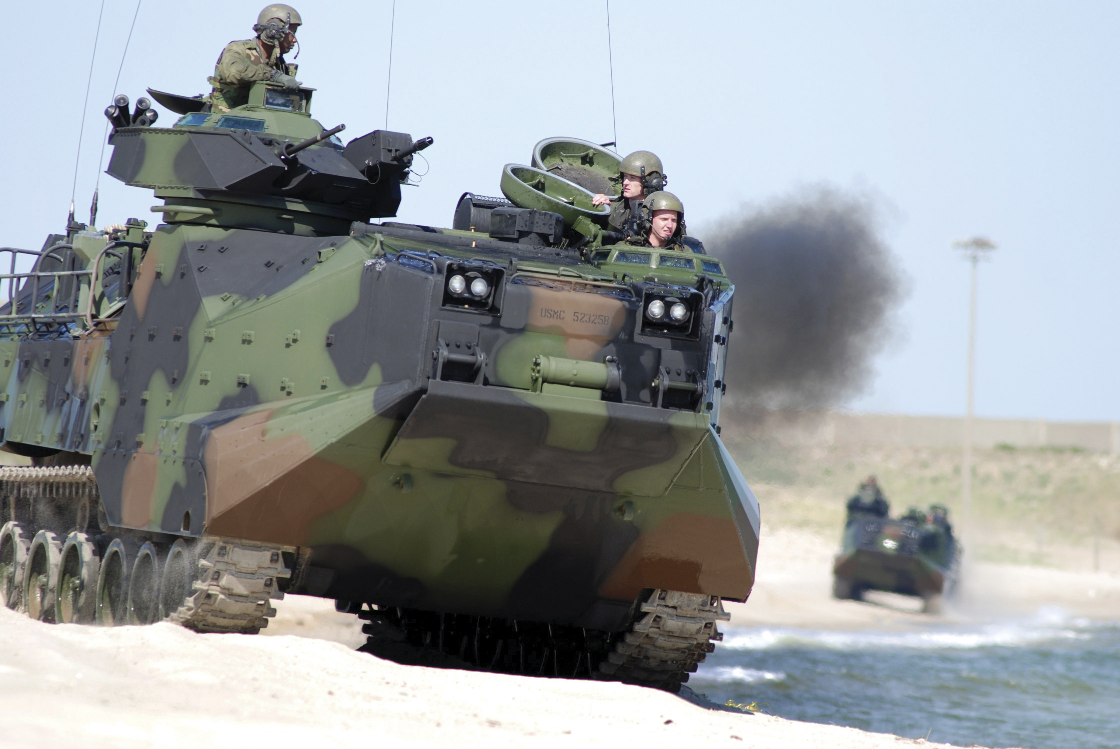
Amphibious assault vehicle (AAV), U.S. Marine Corps.
In this navigation context, AR was developed for use in low-visibility situations, such as navigating in dense fog or at night during lights-out missions. The technology can provide a visual depiction of critical points of interest, regardless of real-world visibilities. AR provides the means to integrate sensors and supporting geographic information system and related systems into a cohesive visual display that overcomes environment limitations or such things as closed-hatch operations on military vehicles.
AR delivers two important military capabilities to the warfighter: situational awareness and precision piloting capabilities, both key to survival on the battlefield.
Situational Awareness. Any information with a geographical registration component can be overlaid on the real-world view in a single composite display format. This can track data, threat locations, friendly-force locations, obstacles, and safe havens; the list grows each day. This information adds immensely to the operator’s understanding of the environment. This fused information, over a real-world, real-time view, is functionally an enhanced Common Operational Picture (COP). Operators can be more cognizant of the tactical situation day, night, or in any visibility condition.
Precision Piloting. The faster one drives in an automobile, the further down the road one must focus to stay on the highway. AR provides this look-ahead drive-to-position based on accurate GPS positions. This extends the importance of GPS to high-speed operation or very close maneuvering situations where humans cannot cycle through a chart or map display, then place themselves in the real world to make maneuvering decisions.
AR enables a rich suite of functions supporting the access and maintenance of a COP, and demonstrated maneuver accuracy. For the Augmented Reality Visualization for the Common Operational Picture (ARVCOP) system, any situational awareness information available can be overlaid on the real-world view in a clear and organized way. Operators do not have to go through the process of translating what they see on a map to what they see in front of them, a translation process that often incurs error. AR then delivers this to warfighters through a human-cognition friendly, integrated display of sensor data and geographically registered overlays, as Figure 1 illustrates. The AR view is shown along with a two-dimensional view on the right side of the display.
Figure 1. ARVCOP display example.
Developed by the Office of Naval Research with industry partner Technology Systems Inc., ARVCOP provides a human-machine interface that can magnify the effectiveness of precision positioning. In this article, we discuss how AR is utilized in this context and the results of testing AR precision-navigation systems aboard Marine Corps amphibious assault vehicles (AAVs, see photo) on the beaches of Marine Corps Base Camp Pendleton, California.
Precision piloting, or driving accuracy, is achieved by providing the operator a point toward which to drive that is in relation to the current position. Testing showed that looking ahead or driving to a point forced the operator to self-correct for the effects of wind, waves, and current.
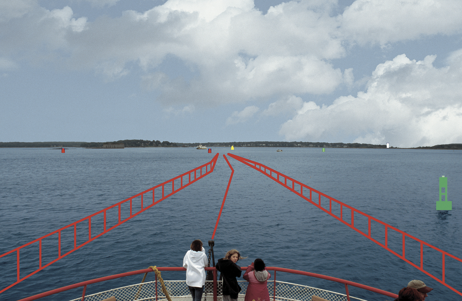
AR is exemplified by a software application that combines real-time video imagery with virtual images to provide a new dimension in navigation piloting accuracy. Figure 2 is an AR display on a ferry boat showing the navigational route marked by rails.
Figure 2. Real world with augmented reality.
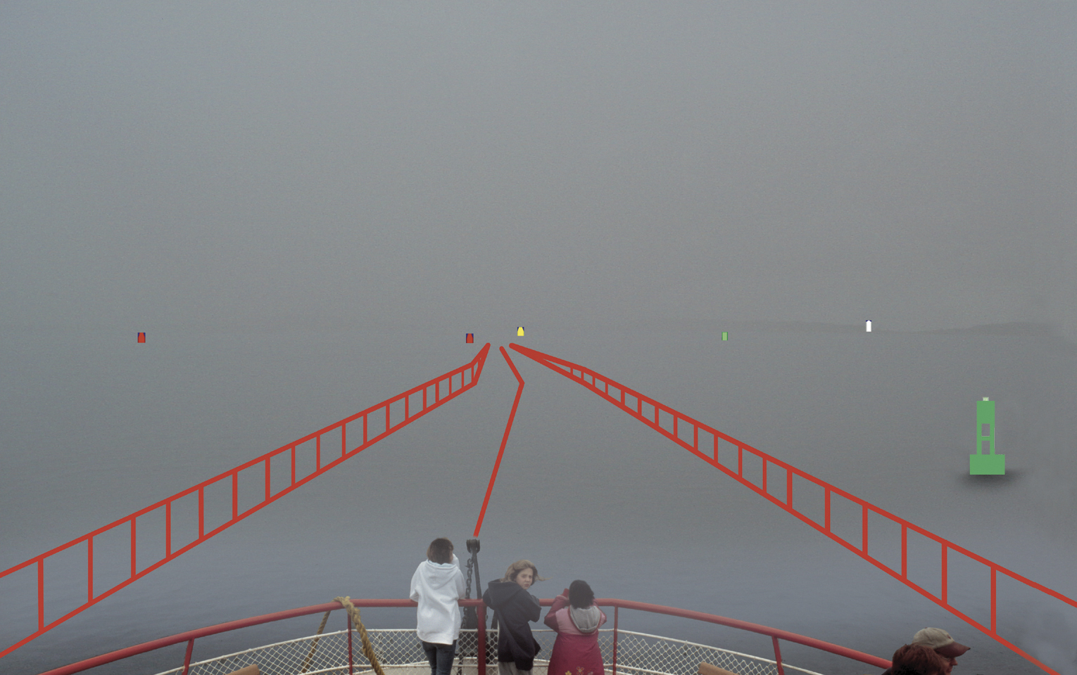
AR can overlay critical chart information such as buoys and channel markers, as well as radar or automated information system (AIS) contacts. In fact, any information that has a geo-registration component (geographic location attached) can be precisely overlaid on a real-time or infrared camera view. Operators have reported they are able to maneuver in unfamiliar waters at high speed with confidence, especially at night or in inclement weather (Figure 3).
Figure 3. Obscure visibility with augmented reality.
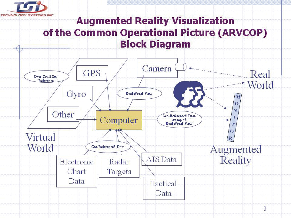
An operator using AR does not have to look down at a chart, radar, or AIS display, and then up at the real world to put the information into context. Charts, radar, and AIS output 2D information that must be made relevant to a 3D world. Analysis shows that converting 2D to 3D is a strenuous and error-prone task for the brain. Accidents can be caused by an initial mistake, which is then compounded by other decisions made with incorrect information. Figure 4 shows how AR automates the conversion process, allowing the human to focus on other relevant tasks.
Figure 4. Augmented Reality Visualization of the Common Operational Picture (ARVCOP) block diagram.
R & D Hardware
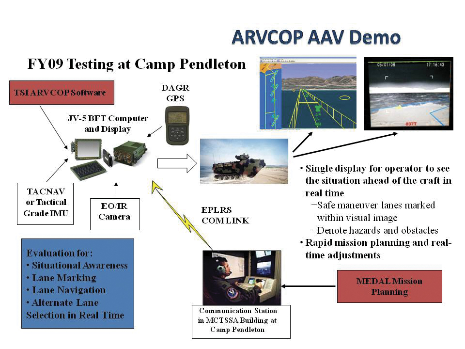
AR applications on AAVs have demonstrated the technology’s utility on land, in water, and through the hazardous surf zone, delivering precise routing through cleared transit lanes. The system is intuitive to operate. Operators with little or no training in AR systems executed precise maneuvers through lanes planned with bends and turns. The AR system used a military GPS and heading device. Electronic chart and tactical data brought positional context to the display. A virtual world was created and software algorithms draped the virtual world over a real-world camera view creating an AR display (Figure 5) for the AAV test.
Figure 5. AAV with research and development commercially available ARVCOP hardware.
Camp Pendleton Tests. In 2009, rigorous testing was completed for the ARVCOP system using AAVs in the surf at Marine Corps Base Camp Pendleton. Safe maneuver lanes were marked with mine-like objects and other hazards. Complex routes that included turns and zigzag patterns were planned toward the beach. Routes were delivered to vehicles using a radio circuit, and adjustments to the planned route were made on the fly to adapt to changing tactical situations.
The AAV is a 26-ton vehicle that is a challenge to operate when placed in a surface environment with wind, waves, and currents. Hardware employed ranged from legacy devices, including a magnetic heading device, to modern devices. With Research and Development (R&D) hardware, the results were dramatic compared to the traditional means of navigating assault lanes. The technology enabled new mission concepts, such as irregular routes ashore and avoidance of hazards sighted by other forces as the mission was in progress. The evaluation criteria for these tests were cross-track errors (CTEs), measured relative to a planned route. Separate, high-accuracy GPS was used for truth data to measure the accuracy of the route driven. Figure 6 shows the video camera and GPS antenna locations on the AAVs.
Figure 6. Video camera is located directly beneath the GPS antenna.
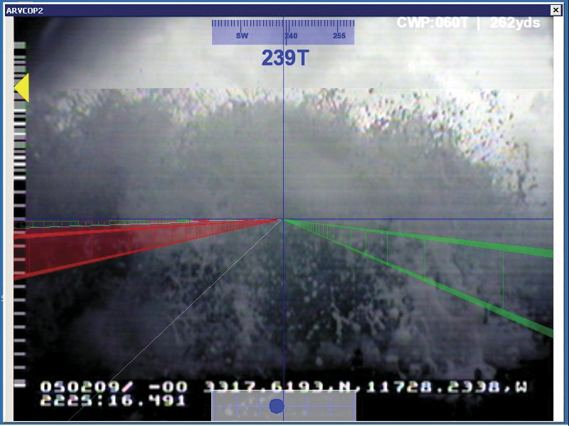
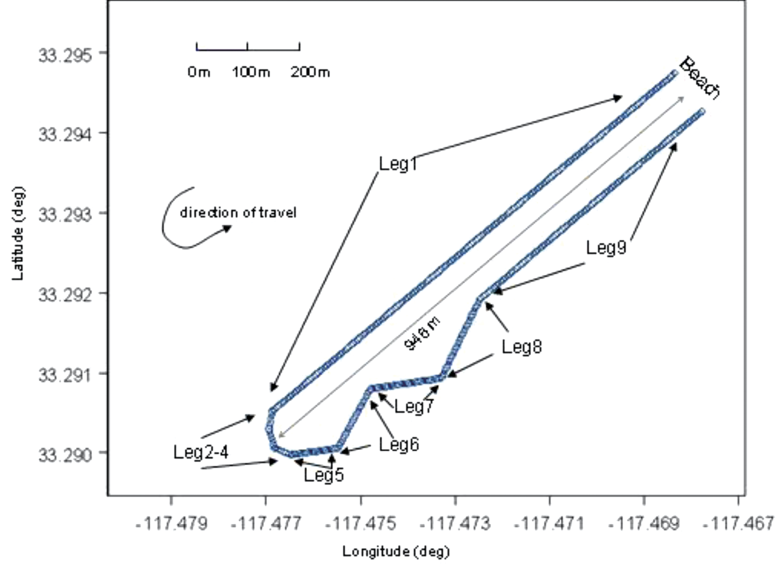
Figure 7 gives an example of the resultant AR video imagery for the R&D commercially available hardware on the AAVs. Figure 8 shows the planned routes for the R&D test evaluations. The distance offshore was 946 meters, and the planned total route length was 1,990 meters.
Figure 7. ARVCOP video using R&D hardware.Figure 8. Planned route for the R&D testing.
Video Augmentation Accuracy
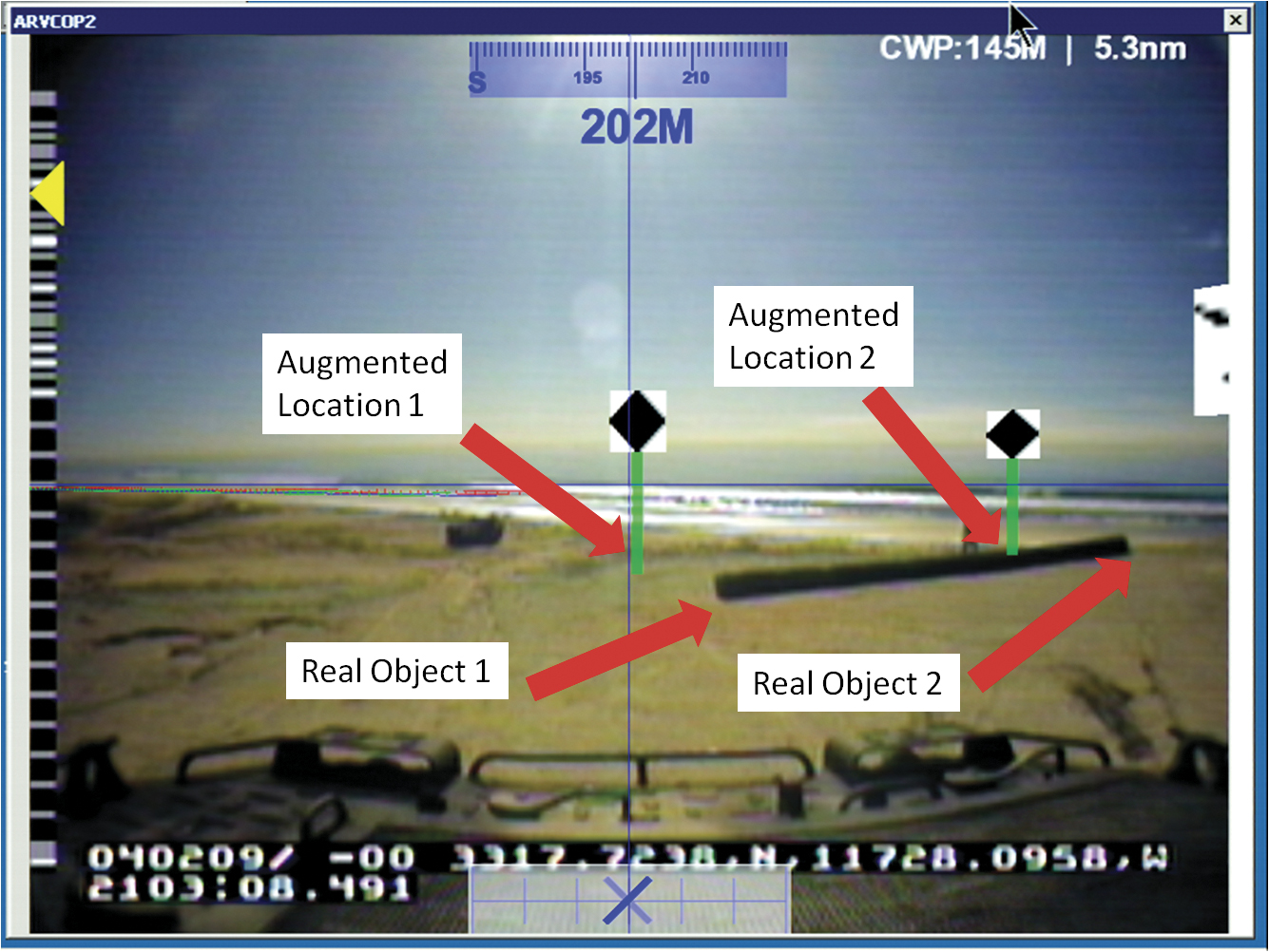
To determine position accuracy of the augmented figures drawn on the video images, time encoded images were captured. The augmented images were captured by ARVCOP using both the Civilian-Miniature Integrated GPS/INS Tactical System (C-MIGITS III) and the Tactical Navigation Digital Compass System (TACNAV) as input devices. Typically, multiple images are used to determine reference frame biases between the camera and the inertial measurement unit but, in this case, multiple image solutions lacked convergence. For this analysis, single-image solutions were generated. Figure 9, which shows locations of virtual and real objects, is an example of an image used in this analysis. The reference location of the virtual object is the bottom of the green post. The real-object coordinates input to ARVCOP were generated using a GPS survey and have centimeter-level accuracy. Figure 9 illustrates the inaccuracies in the system. During this calibration test, the augmentation showed errors of about 100 mrad (6 degrees) in the display of the virtual objects. (Authors’ note: This paragraph accurately reflects system performance on that day three years ago. Shortly after the test, system modifications were made that eliminated much of that error.)
Figure 9. ARVCOP image captured showing virtual and real objects.
Test Results
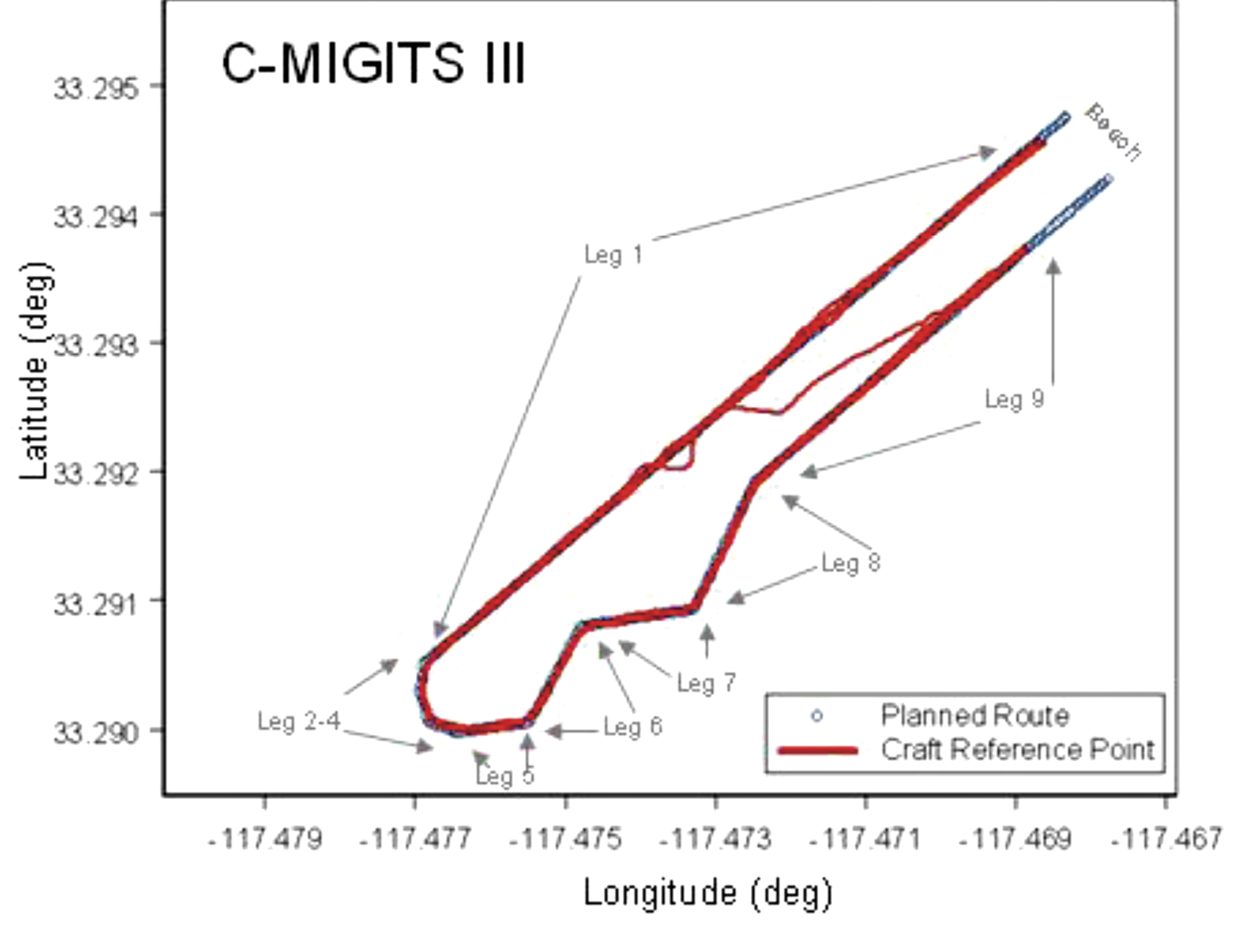
Evaluation of the AAV operation using ARVCOP as a driver’s aid was done by comparing the planned route with the actual route driven. The comparisons were made by finding the distance normal to the route, input to ARVCOP, and the vehicle’s estimated positions, generated using a GPS-relative positioning technique; no vehicle heading information was used and only horizontal components were compared. These differences between planned and executed routes are the CTEs. As mentioned earlier, both the C-MIGITS III and the TACNAV were used as input to ARVCOP for these tests. Figure 10 shows an example of the raw data, with the ARVCOP planned route (blue) overlaid with the GPS estimated positions (red). In this example, ARVCOP used C-MIGITS III heading input updated at a 10-Hz rate.
Figure 10 illustrates how the AAV stayed on the planned course, showing only small deviations. The blue line represents the planned route and the red points are the GPS-estimated positions.
Figure 10. AAV planned and actual route, Run 2.
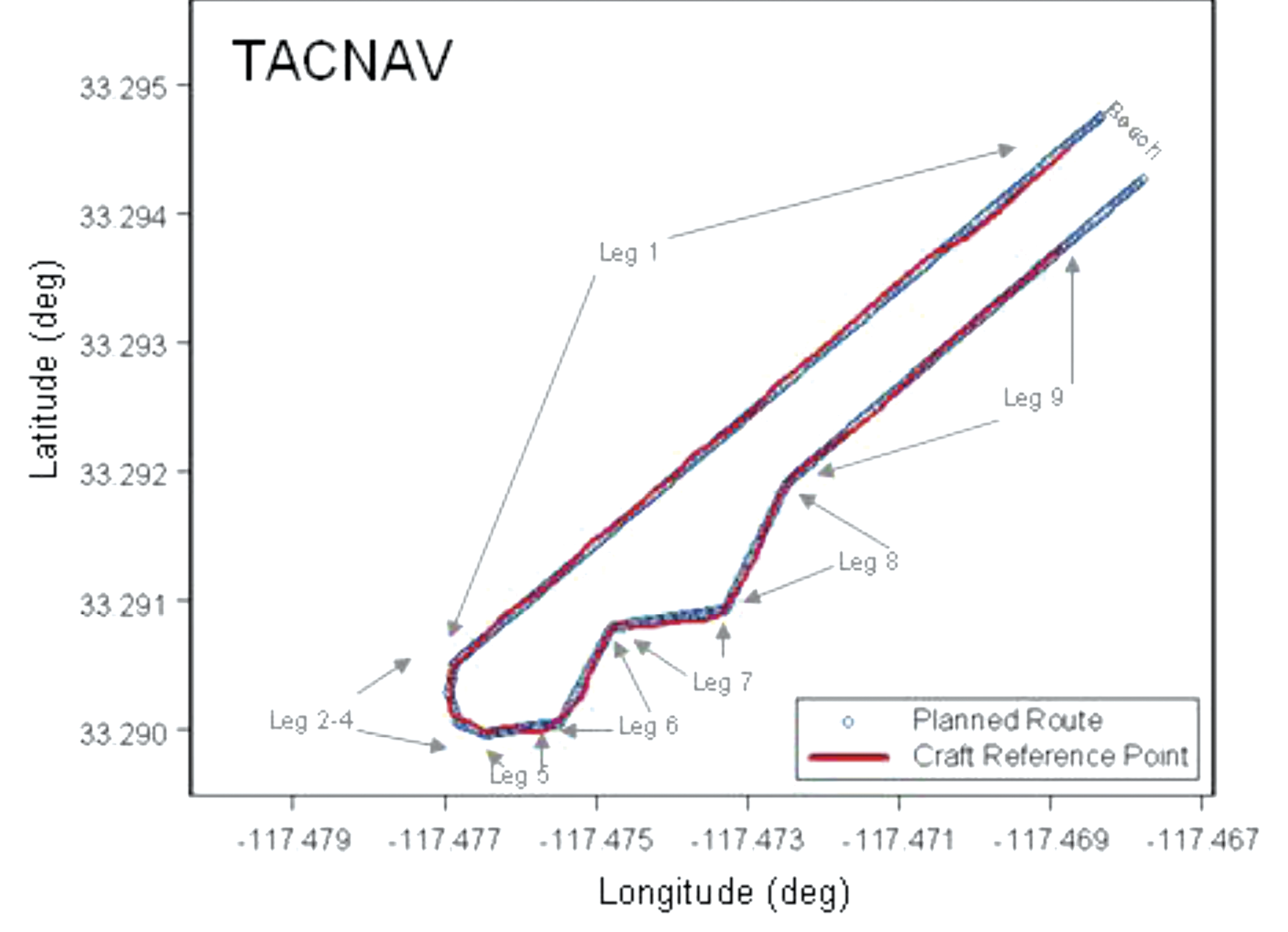
When TACNAV was employed to supply heading information, similar results were seen. Figure 11 shows the first run made with TACNAV heading estimates. The AAV stayed on planned route except for some minor deviations.
Figure 11. AAV planned and actual route, Run 5.
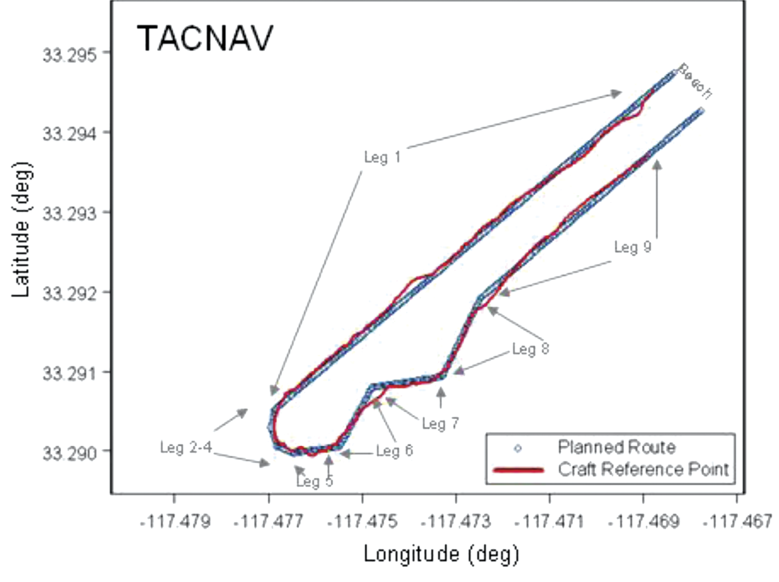
Figure 12 is of the second run using TACNAV heading information. In this instance, larger and more frequent excursions from the planned route are shown. The differences between Figures 11 and 12 are the result of the driver’s interpretation of the ARVCOP display. When the TACNAV was used as input to ARVCOP, the driver’s display showed greater instability than when the C-MIGITS III was used. The instability was a 1-Hz, few-degree shift in augmentation on the video corresponding to the TACNAV input rate. Figure 12 shows the result of the driver trying to follow all the augmentation shifts. When the driver ignored the sudden shifts in augmentation and drove a perceived average route, the resulting track was smoother, as Figure 11 shows. The 1-Hz input rate and the inherent TACNAV variations both contributed to the augmentation’s jumpy appearance.
Figure 12. AAV planned and actual route, Run 6.
Figure 13 shows the tracks of all the runs from the February 2009 tests that used the C-MIGITS III, except for runs 7 and 8. Run 7 was excluded because high surf caused its early termination when the vehicle was ordered to shore by the safety officer. The driver’s display was lost during Run 8 because of a loose cable and the test was aborted.
Figure 13. AAV planned and actual route, C-MIGITS-III heading data.Table 1 (left) shows the CTE statistics for the C-MIGITS–III runs. Table 2 (right) shows the CTE statistics for the TACNAV runs.
Table 1 shows the CTE statistics for the C-MIGITS–III runs. Table 2 shows the CTE statistics for the TACNAV runs. Average speed over the course varied from 4 to 5 knots. It took about 15 minutes to drive the entire route.
Discussion
Comparison of the heading estimates between the C-MIGITS III and the TACNAV estimates showed variations of about 3 to 5 degrees, after removal of a bias. Investigation of the relationship of the heading angle error with the heading angle showed that after TACNAV calibration, significant heading error correlations remained in its estimates. Using the TACNAV as a source of heading information showed that the slower 1-Hz update rate and inherent variations of the sensor degraded the augmentation software’s performance. For example, when using the TACNAV, the augmented lane boundaries occasionally jumped a few degrees corresponding to the receipt of heading estimate updates. This was particularly evident after vehicle turns. The C-MIGITS III 10-Hz update rate and higher accuracy estimates enabled ARVCOP augmentation without distracting artifacts and provided the driver with more accurate navigation information. The ARVCOP-augmented objects were drawn on the video with a heading accuracy of about 6 degrees.
During February 2009 R&D tests, the AAV made eight surf runs using ARVCOP with C-MIGITS III input and two runs using TACNAV input. CTE statistics for the ARVCOP C-MIGITS-III testing showed rms differences of about 2.9 meters. The ARVCOP TACNAV testing showed larger rms differences of about 4.9 meters. These statistics represent the rms error between the AAV’s planned and executed route.
Summary
AR technology provides a human-machine interface for a navigation system enabling precise maneuvering. ARVCOP presents navigation data so intuitively that operators are able to multitask as required in mission performance while still being able to precisely maneuver. ARVCOP proved the concept of AR-based precise navigation in rigorous operational scenarios with the U.S. Marine Corps (USMC).
Test results for the R&D commercially available civilian GPS/INS hardware provided CTE of mean 2.1 meters and standard deviation of 2.0 meters. Operational hardware was evaluated in July 2009 over four days of testing, including 47 runs, in conditions with sea states ranging between 1 and 2.5, and many drivers. In 2010, at NSWCDD and Naval Surface Warfare Center, Panama City Division (NSWCPC), land demonstrations were performed with similar hardware navigating cleared paths through simulated mine fields at night. Vehicles were able to transit cleared routes with no external markings. The Naval Sea Systems Command Program Manager, (PMS 495), Mine Warfare Office, is now installing ARVCOP on USMC AAVs.
Acknowledgments
This work was sponsored by Brian Almquist, program officer, Ocean Battlespace Sensing Science and Technology Department, Office of Naval Research. LtCol Brian Seiffert, USMC, acting director of the Amphibious Vehicle Test Branch (AVTB), Camp Pendleton, supported the demonstration. GySgt Chapa and SSgt Schaefer, USMC, coordinated the AVTB effort. Kennard Watson, NSWCPC, coordinated the Camp Pendleton test plan. William Chambers, Maritime Technology Consulting LLC, Udayan Bhapkar, Andrew Sutter, and Alan Evans, NSWCDD, supported the tests and evaluations. Ronald Paradis, KVH Industries, Inc., supported heading sensor calibration.
Manufacturers
The C-MIGITS III is made by Systron Donner Inertial Division (www.systron.com) and TACNAV by KVH Industries (www.kvh.com).
Tom Zysk (captain, U.S. Navy, retired) has more than 35 years of experience in the Department of Defense and industry. He held positions with Raytheon and General Dynamics before joining Technology Systems Inc.
Jeffory Luce is a senior program manager at Technology Systems, Inc. (TSI). As lead for the ARVCOP program, he successfully transitioned TSI’s first project to a Program of Record.
James Cunningham has worked in GPS research and development at the Naval Surface Warfare Center, Dahlgren Division, for more than 25 years
As the cost of GIS data collection devices (handheld, tablet) has plummeted in the past two years and smartphones have proliferated, the quest for inexpensive GIS data-collection software has intensified. It makes sense. When people were used to paying thousands of dollars for a GIS data-collection device, another US$800-$1,000 for GIS data collection software seemed reasonable. It might have added 15-25% to the total price of the system. With today’s inexpensive devices, sometimes data collection software ends up costing more than the device itself, thus pushing the demand for cheaper software. On top of that, as I discussed a couple of weeks ago, we are in the middle of a mobile device operating system war. Whereas it used to be a no-brainer that Windows Mobile (or some derivative of it) was going to be the dominant operating system and supported by software developers, that’s not the case any longer. Windows Embedded is going to be around, but it’s clearly not the dominant mobile device operating system it once was.
Interestingly enough, GIS data collection software for iOS and Andoird have followed the iOS and Android price trends. The mobile devices running iOS and Android are inexpensive, sometimes free. You don’t see any iOS or Android GIS data collection software packages costing thousands of dollars. On the other hand, many Windows Mobile-based geospatial softwares cost upwards of US$2,000. Of course, you can make the argument that the Windows Mobile-based softwares are mature and feature rich. That’s true, as most of the iOS and Android-based softwares have a fraction of the capability, but I’d venture to say that most users don’t need many of the features they are paying for. I also agree with one of the trends outlined in the UN document in that I think open source might be where things are headed.
Free and open source software will continue to grow as viable alternatives both in terms of software, and potentially in analysis and processing.
Ironically, open source GIS data collection software has been around for years. However, you probably don’t know about it because no organization is actively marketing it (if there’s no revenue, there’s no marketing budget). Software like gvSIG Mobile is a reasonably powerful GIS data collection product. A little quirky? Perhaps. But, if your budget is depleted and your requirements exceed the capabilities of the typical free or inexpensive software in the iTunes or Google Market, you might tolerate the quirkiness.
gvSIG Mobile Open Source GIS Data Collection Software.
The UN also predicts that geospatial data will trend toward open source.
Within five years the level of detail on transport systems within OpenStreetMap will exceed virtually all other data sources and will be respected and used by major organizations and governments across the globe.
Community-based mapping will continue to grow.
There is unlikely to be a market for datasets like those currently sold to power navigation and location-based services solutions in five years, as they will have been superseded by crowdsourced datasets from OpenStreetMaps or other comparable initiatives.|
While I agree that the trend towards open source data is gaining traction, five years is a really aggressive timeline for phasing out the likes of TeleAtlas (owned by TomTom) and Navteq (owned by Nokia). These are the two major map database suppliers for virtually all GPS navigation devices used in vehicles around the world. I think there will be, for the forseeable future, a quanitifiable and valued difference between open source data and commercial geospatial data. Commercial users will pay for perceived quality and accountability, especially if the price differential is minimal. Consumer GPS users (vehicle navigation) might be a different story. A $30 difference in retail price can sway a consumer from one brand to another.
More on UAVs for Mapping
One of the first trends in the UN listed are:
There will be an increased demand for applications to be used with high-resolution imagery.
The use of Unmanned Aerial Vehicles (UAVs) as a tool for rapid geospatial data collection will increase.
Cost-effective mapping UAVs are starting to emerge. In just this past week, Event 38 announced a small mapping UAV for under US$1,000.
Low-cost E382 Mapping UAV from Event 38.
Augmented Reality
As does the UN vision, I think augmented reality has a bright future for both commercial users and consumers.
Augmented reality applications will be pervasive, with the ability to view a whole range of data overlays on top of the real world.
For professional geospatial users, the situational awareness possibilities are tremendous. Imagine the backhoe operator being able to “see” the underground infrastructure in order to avoid it. Imagine the park superintendent being able to “see” all of the underground irrigation and drainage lines by simply positioning a tablet computer towards the area of interest.