Tag: aviation

  • GSA Releases First GNSS Market Monitoring Report

    The European GNSS Agency (GSA) has published a 2010 GNSS Market Monitoring report, providing key information in support of entrepreneurship in the satellite navigation sector.

    GNSS market forecasting is of great interest to private and public GNSS stakeholders, for business and strategic planning and policymaking, said the GSA. According to the new report, the market for GNSS will grow significantly over the next decade, at a compound annual growth rate (CAGR) of 11 percent, reaching €165 billion for the core GNSS market in 2020. Delivery of GNSS devices will exceed one billion per year by 2020.

    “This Report confirms that the market potential of GNSS is significant,” said Gian Gherardo Calini, head of the GSA Market Development Department. “The information should be useful to researchers, market players and decision makers who want to grasp the GNSS market opportunities today and tomorrow.”

    Report Highlights

    Road leads the way: The report shows that the road transport sector is still the leading GNSS segment, accounting for more than 50% of market share. The penetration of receivers in road vehicles, today at 30%, will exceed 80% over the next decade. However, after a period of fast growth, market saturation and competition in the form of ‘smartphones’, often equipped with free navigation capabilities, have resulted in a slowdown in the car-based navigation market.

    Price erosion has been high, driven by declining costs and strong competition. Vendors are using innovation as a differentiator resulting in ‘converged’ products with both communication and multimedia functionalities. Some Personal Navigation Device (PND) vendors are also tapping into new distribution channels, including car dealerships and smartphone application stores.

    GNSS for road transport: The road transport sector is facing major challenges, such as the demand for increasing safety and for reduced congestion and pollution. These problems are particularly acute in highly populated zones, including big cities and suburban areas. GNSS represents a powerful tool for improving road transport. Not only does it help get drivers where they want to go more quickly and efficiently, but it also promises fairer road-pricing schemes, for example, to automatically charge drivers for the use of road infrastructure.

    GNSS in your hands. Mobile location-based services (LBS) are taking off as progress is being made in different areas. More and more mobile phones now have GNSS capabilities, the result of both increasing consumer and developer awareness and an improvement in navigation services and performance.

    All major mobile phone operating system vendors now provide application programming interfaces (API) with location functions. In 2009, in the UK, France and Germany, 5 out of the 10 best-selling iPhone applications were related to navigation or location-based applications. Also, 30% of Android developers’ contest winners used location capabilities in their applications.

    A promising future for location-based services.
    The integration of accurate hand-held positioning signal receivers, within mobile telephones, personal digital assistants (PDAs), mp3 players, portable computers, even digital cameras and video devices, brings GNSS services directly to individuals, making possible a fundamental transformation of the way we work and play. The penetration of GNSS in mobile phones is therefore expected to increase very quickly, from some 20% today to above 50% within the next five years.

    The GSA says Galileo in the future and EGNOS today open up new and exciting prospects for economic growth, benefiting citizens, businesses and governments throughout the EU and beyond.

    Just the beginning. The GSA underlines that the GNSS Market Monitoring process is ongoing and future reports are planned to update information presented in this first report and to cover other sectors. The Agency welcomes stakeholder contributions.

    The 2010 GSA Market Monitoring Report can be downloaded free.


  • Where Time and Space Meet

    Where Time and Space Meet

    Sensor Modeling and Sensitivity Analysis for a Next-Generation Time-Space Position Information System

    By Mark Smearcheck and Michael Veth, Air Force Institute of Technology

    Increasing availability and performance of state-of-the-art navigation sensors motivates the need for a highly accurate reference system commonly referred to as a time-space position information (TSPI) device. The Advanced Navigation Center at the Air Force Institute of Technology is working with the Air Force Flight Test Center to develop a next generation time-space position information (TSPI) system to be used for test and evaluation of modern navigation devices.

    TSPI systems such as the GPS Aided Inertial Navigation Reference (GAINR) or Advanced Range Data System (ARDS) accompany navigation sensors during flight testing to collect the precise position, velocity, and attitude. Current GAINR TSPI performance levels include 1.0 m of position uncertainty, 0.1 m/s of velocity uncertainty, and 1.75 mrad of attitude uncertainty. Goal performance levels for next-generation TSPI call for an order of magnitude improvement over current systems.

    A more accurate test and evaluation device will likely require fusion of multiple sensors of varying modalities such as GPS, inertial, electro-optical and infrared cameras, laser range sensors, barometric altimeters, ground-based theodolites, and ground-based tracking radar. This research aims to identify an integrated sensing package and the sensing techniques required to achieve the next generation TSPI accuracy.

    In order to accomplish this task, a sensitivity analysis is performed that predicts the quality of the navigation solution attainable using various external sensor combinations. The sensitivity analysis requires sensor characterization and modeling in addition to development of a software simulated world (the flight test range) that the sensors are able to observe. Issues also investigated in this research include vision-aiding techniques, optical feature deployment, and testing in GPS-denied scenarios.

    PHOTODEVICE
    The GPS Aided Inertial Navigation Reference (GAINR) system consists of a Honeywell 764-G embedded GPS/INS with a custom control and recording unit. The data are post-processed using an optimal smoother and differential GPS measurements.

    Sensors and Simulated World

    The Air Force Flight Test Center currently obtains TSPI using the GAINR, which includes a navigation grade inertial measurement unit (IMU) and dual-frequency code-based differential GPS (DGPS). Carrier-phase GPS, if available, could be implemented to increase position accuracy.

    When integrated into a highly dynamic platform, such as tactical fighter, a kinematic solution may not always be obtainable due to difficulty resolving integer ambiguities and cycle slips experienced in the receiver’s tracking loops. The sensitivity of both code and carrier-phase differential GPS is included in this research due to the uncertain availability of a kinematic solution.

    Scenarios of GPS denial are always an area of concern for the warfighter, and thus GPS-independent test-platforms must be examined. Other positioning sensors, useful in GPS-denied testing, include ground-based theodolites and radars. These devices are installed at surveyed locations on the test range and are used to track the test aircraft. Theodolites are pivoting platforms that may contain various sensors and provide range, azimuth angle, and elevation angle measurements. Radars are also used to provide the same type of measurements, along with an additional velocity measurement (Figure 1).

    overview
    Figure 1. Overview of possible TSPI sensors. The sensors consist of both aircraft-based and ground-based devices.

    Onboard optical sensors including high-resolution digital cameras and laser range finders have also been investigated for TSPI use. This research proposes to install surveyed targets on the test range that are easily identifiable through feature extraction and tracking methods such as the scale-invariant feature transform (SIFT).

    Cameras are able to observe position and attitude through homogenous pixel location measurements of image features (FIGURE 2).

    FIG2
    Figure 2. Simulated test range at Edwards AFB that includes optical targets, ground sensors, and a flight test profile. Optical landmarks are randomly spread within the field of view of the optical sensor over the trajectory.

    An objective of this sensitivity analysis is to show the attitude performance achievable through feature tracking of surveyed targets. When image-aiding of an IMU is implemented in a navigation filter, such as the extended Kalman filter (EKF), next generation TSPI level attitude accuracy should be reached.

    The other optical sensor investigated, the laser range finder, is used to augment the navigation solution by measuring distance to the surveyed targets detected by the camera.

    For the sensitivity analysis a simulated world is generated for the sensors to make observations. The world simulation includes GPS ephemeris, a digital terrain elevation database (DTED), gravity models, natural terrain landmarks/targets, manmade targets, a ground sensor deployment map, simulated flight test profile, and vehicle sensor installation lever-arms.

    Sensitivity Analysis

    The goal of the sensitivity analysis is to determine the minimal set of sensors that will meet next generation TSPI performance requirements. Sensor models and world characteristics are used to calculate expected position, velocity, and attitude uncertainty given a particular trajectory, sensor package, and feature set. The aircraft’s state vector, x, as a function of the measurement, z, and uncertainty matrix, R, is represented as

    EQ1

    where H is the observation matrix. The observation matrix is a Jacobian made up of partial derivates of each sensor’s measurements with respect to position, velocity, and attitude. Example H matrix elements include the partial derivates describing the camera measurements with respect to position and attitude. The partial deviate of the pixel coordinate, zi, of an image feature with respect to position, pn, is

    EQ-2

    where Tcpix is the camera frame to pixel frame transformation matrix made up of calibration parameters, sc is the line of sight vector from the camera to the target expressed in the camera frame, Cnb and Cbc are direction cosine matrices, and the subscript z denotes the z dimension of the indicated navigation frame. The partial derivative of the pixel coordinate of an image feature with respect to attitude, α, is calculated as

    eq3

    The H matrix’s partial derivatives describing observations from other navigation sensors are derived in our previous
    work, “Sensor Modeling and Sensitivity Analysis for a Next Generation Time-Space Position Information (TSPI) System,” Proceedings of the ION International Technical Meeting, 2010. The a posteriori uncertainty of the state or sensitivity, P, at time k is calculated as

    eq4

    where P0 is the initial uncertainty.

    Results

    Results show the three sigma median uncertainty of position and attitude for various sensor combinations over a common flight profile through the test range (Figure 3).

    Smearcheck-Fig3
    Figure 3. Sensitivity analysis results of position and attitude with various sensor combinations. Scenarios of unobservable attitude are designed by the infinity symbol.

    Conclusions

    The sensitivity analysis indicates that the most practical sensor package that meets next-generation TSPI performance is the combination of carrier-phase GPS and a high-resolution camera tracking ten SIFT features per image.

    In this example, tracking only two SIFT features per image does not provide the necessary level attitude accuracy, although incorporating inertial measurements is expected to reduce the overall number of features required per image.

    In the absence of GPS, theodolites when coupled with a camera can function as a reasonable alternative. It should be noted that since the sensitivity analysis relies on a simulated world the feature tracking performance and target surveying accuracy may change during operational testing.

    The next phase of this research is to integrate the sensors with an IMU using an extended Kalman filter. Fusion with a navigation-grade INS is expected to improve position, velocity, and attitude accuracy.

    If simulated results are promising, the next phase of the effort will focus on collecting flight test data to validate the simulation and further increase the fidelity of the simulation.

    Acknowledgment

    The authors would like to thank the Air Force Flight Test Center for supporting this research.


    MARK SMEARCHECK is a research engineer with the Advanced Navigation Technology Center at the Air Force Institute of Technology (AFIT) at Wright Patterson Air Force Base in Dayton, Ohio. He received his B.S. in electrical engineering in 2006 and his M.S. in electrical engineering in 2008, both from Ohio University. His research topics include micro-air vehicles, indoor navigation, image-aided navigation, pseudolites, and test range instrumentation.

    LT. COl. MICHAEL VETH is an assistant professor of electrical engineering at AFIT and deputy director of the Advanced Navigation Technology Center. He received his Ph.D. and M.S. in electrical engineering from AFIT and his B.S. in electrical engineering from Purdue University. He is a graduate of Air Force Test Pilot School.

  • GNSS Vulnerability and Alternative PNT

    As NextGen air traffic management increasingly relies on GNSS for safety-critical functions, some form of backup is needed in the event of GNSS signal loss, whether due to intentional jamming or other causes.

    A group working under the auspices of the Federal Aviation Administration (FAA) Navigation Services Directorate recently prepared a study assessing non-GNSS navigation system architectures to provide alternate positioning, navigation, and timing (APNT) services for aviation users, to mitigate GNSS vulnerability to radio frequency interference (RFI). The APNT architecture would be based on selected elements of today’s terrestrial navigation network, possibly upgraded, plus new elements anticipated for the 2025 timeframe.

    This article summarizes the scope and initial results of the study; to download the full paper, visit env-gpsworld-integration.kinsta.cloud/alternativePNT. As a result of the 2001 Volpe Vulnerability Study and subsequent U.S. government policy on PNT services provided by GPS, the FAA has begun investigating APNT concepts by which the safety, security, and efficiency of the U.S. National Airspace System (NAS) can be maintained in the event of a loss of GPS-provided PNT services. The sought-after APNT network should be cost-effective based on likely aircraft equipage in the 2025 timeframe.

    The FAA recognizes that during migration from the current NAS to the Next Generation Air Transportation System (NextGen), reliance on PNT services will increase to support area navigation (RNAV), digital communications, and enhanced surveillance services. This paper, presented by the FAA to the International Civil Aviation Organization’s (ICAO’s) Navigation Services Panel in May, identifies three major areas of research and analysis. The APNT work represents a constructive response to concerns raised by the simultaneous 9/11 terrorist attacks and the Volpe Report on GPS vulnerability.

    The first area of research proposes to investigate current distance measuring equipment (DME) to see if better RNAV services can be provided to current and future users, and to mitigate the possible problem of over-interrogation as demand on the system grows. The second area will investigate multi-lateration to see how the services based on systems currently being planned and fielded could be expanded or enhanced by synergy with other ground-based navigation systems such as DMEs.

    The third area of interest will investigate the use of the current and future DME network, and potentially other ground-based equipment, to provide a robust RNAV pseudolite system broadcasting in the current DME L band. This third alternative receives the bulk of the attention of this two-page digest of the full paper.

    Background

    The United States is pursuing the NextGen air traffic modernization program to support a predicted increase in operations by a factor of 2–3 by 2025. Many of the new capabilities depend on PNT services provided by GNSS. Specifically, performance-based navigation (PBN) and automatic dependent surveillance broadcast (ADS-B) will be based on GPS with satellite-based augmentation systems (SBAS) and ground-based augmentation systems (GBAS). PBN and ADS-B will, in turn, support trajectory-based operations, area navigation (RNAV), required navigation performance (RNP), precision approach, closely spaced parallel operations, and other operational improvements.
    As NextGen modernization and implementation progresses, U.S. NAS dependence on GNSS services will increase. Appropriate mitigations for GNSS vulnerability to RFI also must be assessed and implemented where necessary.

    APNT Assumptions

    The study group established a set of assumptions to guide the analysis activity. Key among the 13 assumptions were:

    • In 2025, there will be “RNAV everywhere and RNP where beneficial.” There will likely be many different variants of RNAV and RNP that are yet to be defined.
    • APNT is a means to continue RNAV and RNP operations to a safe landing during periods when it is discovered that GNSS services are unavailable, due to interference.
    • Users equipped for APNT will be able to continue conducting RNAV and RNP operations (dispatch, departure, cruise, arrival) during the GNSS outage after the transition to APNT.
    • Users not equipped for APNT may not be able to continue RNAV and RNP operations in areas where GNSS is required during the GNSS outage.
    • APNT service performance may not be equivalent to GPS performance.
    • At least one instrument landing system will be retained at airports wherever required for safety or economically justified.

    Pseudolite Multi-Lateration

    This article passes over the paper’s discussion (see link cited earlier for full version) of DME network optimization and passive wide-area multi-lateration (WAM) to take a brief overview of the pseudolite-based multi-lateration.

    As shown in Figure 1, the pseudolite (PL) architecture allocates the position and integrity functions to the aircraft, similar to how GPS receiver-autonomous integrity monitoring works. The PL alternative would leverage all of the existing 1,100 DME facilities plus the planned ADS-B ground-based transceiver (GBT) facilities to provide a combined network of approximately 1,900 sites.

    As shown in Figure 2, the PL architecture requires the GBT and DME sites to be synchronized to a common time standard so each facility can generate and transmit a heartbeat message consisting of the station identification and an accurate time stamp. The ADS-B in avionics would host the position calculation and integrity monitoring functions and pass this information to the aircraft navigation over a new interface, if GPS becomes unavailable.

    Figure 2. Multi-lateration (MLAT) alternative block diagram.
    Figure 2. Multi-lateration (MLAT) alternative block diagram.

    The potential advantages of this alternative include a simpler architecture that does not require a ground system to compute the position of the aircraft. A common non-GNSS or robust GNSS time reference is required.

    Straw Man Signal Design

    The authors propose a straw man signal design for the broadcast of one-way ranging signals from existing DME transmitters. The goal is not to provide a final design for such a signal. They recognize that many modifications and improvements will be required to bring such a function to fruition. Rather, they offer the proposal as a catalyst for the community, and hope that it will serve as a starting point for a vigorous discussion on this critical topic.

    Signal design is directed at these goals:

    • The new signals should be added to the existing broadcast from operational DME beacons without significant degradation to the two-way ranging accuracy provided by the DME beacon to legacy users. The new signals would overlay the existing replies that complete the traditional two-way DME transactions. More specifically, they could be implemented by triggering existing beacon with requests from a pseudo-aircraft located near the operational DME beacon. Thus, they hope to avoid any changes to existing ground hardware and by so doing realize benefit from the entire set of DME beacons in operation today.
    • The new signals should provide one-way ranging to modified avionics. The authors do not wish to modify the ground equipment, but recognize that one-way ranging from a DME station will require new avionics.
    • In addition to one-way ranging, the new signals should also support a modest data capability. This data would include the DME location, DME identification, time information, and a parity field to ensure data integrity. The proposal targets a data capacity around 150 bits per second, because similar capacity has served well for other one-way ranging systems such as GNSS and SBAS.
    • Finally, the new signal should also enable source authentication. The authors feel that signal authentication is needed, becau
      se radio navigation may be subject to electromagnetic attack in the decades ahead.

    The authors then describe and illustrate in seven figures the definition of a DME chip, a do-no-harm criterion, synchronization sequence, data field, data erasures and errors caused by competing channel traffic, data content, and source authentication. They indicate that they are looking at other signal alternatives for the DME band as well. These alternatives would make more liberal use of spread-spectrum technology.


    Authors of the APNT study were Leo Eldredge (FAA), Per Enge (Stanford), Mike Harrison, Randy Kenagy, Robert Lilly (all with Aviation Management Associates), Sherman Lo (Stanford), Robert Loh (ISI), Mitch Narins (FAA), and Rick Niles (MITRE CAASD).

  • Expert Advice: Availability Gaps: Solutions for Aviation

    Directions 2010

    James L. Farrell
    James L. Farrell

    By James L. Farrell

    Recent attention given to aging GPS satellites and availability gaps from lagging constellation replenishment have provoked deep concern, particularly within the aviation community. Available remedies include exploitation of well known but unused methods plus new techniques; those discussed here have future relevance, with or without availability gaps.

    Even with far greater coverage from multiple GNSS, crises could emerge from severely stronger interference levels or other unforeseen events. Advance preparation for any such occurrence would avoid the waste, confusion, and blind alleys that generally arise with the sudden appearance of an emergency.

    GPS lives up to expectations, brilliantly performing as advertised. Even that best-ever performance must and does have tolerance for occasional error; examples, though rare, are well documented. To live with less than perfect performance, the industry relies on integrity testing: comparison checks using extra satellites to detect inconsistencies and exclude questionable data.

    Nevertheless, it is universally recognized that GNSS, even with existing fault detection and isolation or exclusion (FDI/FDE), is still not perfect. The ramifications of growing dependence on GPS have thus attracted more attention. The overall subject can be subdivided into general areas involving the likelihood of:

    • reduced availability and
    • reduced dependability (integrity, its verification, plus backup).

    Although I mainly address the first topic here, the second unavoidably intertwines itself, making it difficult to keep them separate. Despite wide acclaim for the excellent 2001 Volpe Report, commitment to a key means of backup for GPS remains unclear at this time. Possibility of a shortfall calls for a review of both existing methods and procedures, and possible means for closing the gap.

    Current Methods

    Today’s air traffic management  designs demand constant replenishment of instantaneous position by full fixes.

    Full Fix 1 RAIM. When each data vector must be a self-sufficient source of instantaneous position, a requirement arises for enough satellite sightline directions with geometric spread at all times. That interdependence is magnified when more satellites are added to provide FDI/FDE, requiring every subset of four within the enlarged group to support the requisite geometry. With this all-or-nothing posture, data lapses form a major stumbling block. A data gap that is only partial equates to a loss of GPS.

    Position-Oriented Approach. Especially at high speeds, as in flight, instantaneous position is highly perishable. With little or no emphasis placed on accurate dynamics (beginning with velocity), demand for continuously accurate instantaneous position is highly dependent on abundant data. That abundance includes sufficiently high data rates, since latency becomes a significant liability without usage of a dynamic file.

    Carrier Phase (Classical). Successful use of carrier-phase information is decades old. Although ambiguity resolution is not required in all carrier-phase applications, requirements for cycle-slip detection are quite common. More common yet — in fact, virtually ubiquitous — is the need to maintain phase continuity via a carrier-track loop. When those needs are satisfied, sub-wavelength instantaneous position is obtainable. Challenges involved, however, have produced among users a wide variation in perception of value. Some negative perceptions have arisen due to cutting corners in formation of carrier phase, or merely settling for delta range, by some receivers. Further, a cycle slip, even if only rarely overlooked, can be catastrophic in some operations.

    Imperfect Validation. As already noted, verification is not my main topic here, but the issue is inescapable. Shortcomings include hard evidence of certification improperly bestowed, and severe limitations of go/no-go criteria (as with an automobile’s dashboard warning lights, we can learn if a performance trait is unsatisfactory — but a trivial excess produces the same indication as an imminent danger).

    Necessary Changes

    Extremely powerful and versatile means to improve performance have been available for a very long time. Kalman’s original paper, half a century ago, formalized an optimal way to achieve such performance. While Kalman estimation is commonly used today, its effective reach is almost invariably limited to data resident within each proprietary box of equipment.

    The resources for providing centrally processed solutions for data from every source of information available, any combination of sources, any subset that may exclude any sensor or group, or any individual source in a federated configuration, are well known. Every conceivable choice from among these solutions can be made concurrently available; note the inherent backup.

    However, all this capability is forsaken or lost by continued use of:

    • interfaces chosen poorly or from outdated standards;
    • undue consolidation within isolated equipment packaging;
    • overextended proprietary rights; and
    • limited, demonstrably flawed validation methods.

    Drop Demands for Full Fix. An immediate explosion of benefits can follow from acceptance of partial information. Countless examples could be cited, but two obvious ones suffice:

    • Within GPS or GNSS, not all space vehicles (SVs) would be simultaneously affected by scintillation; ionospheric disturbance effects vary with both location and time. A similar case holds for multipath. Data from some SVs could be rejected, by decisions made external to a receiver, without forcing rejection of all.
    • Central processing — not within any one equipment box — has always offered potential for other sources (distance-measuring equipment or DME, and so on) to make up for incomplete sets of SV data.

    My broad goal here is to take advantage of information not currently used and to prescribe corrective strategies. That objective has not been widely pursued due to perceived lack of urgency. GPS availability has thus far been more than satisfactory to a multitude of users — but that could change.

    Availability Enhancements. For about two decades, the industry was effectively guided by a strong preference for the trait whereby every data refresh event was self-sufficient. A major reason for this was protection against gradual veering: a snapshot sequence is less sensitive than a continuously evolving path estimate. The cost, of course, is forfeit of benefits conferred by the sequence’s history. More recently, a middle ground was sought to mitigate the resulting loss; subfilters used as much new data as possible while making some use of knowledge from an estimator’s covariance matrix.

    I promptly endorsed that approach and sought to carry it to the limit. A single-measurement receiver-autnomous integrity monitoring (RAIM) resulted, offering an independent integrity test for each separate observation. Despite its rigorous derivation, the technique is quite simple in practice. Further, it bridges a gap that formerly separated integrity test from optimal estimation, while also having significant advantages over conventional RAIM:

    • separation translates to independence from other satellites, and therefore from geometry (effective DOP of unity)
    • ability to use different error variances for different observations (for example, with nonuniformity in signal strength and/or elevation).

    With this discussion, we have clearly left the realm of well-known subjects with self-evident prescriptions. Much of what follows likewise falls into the category of relatively obscure methods.

    Beyond Position-Oriented. A time history
    of GNSS observations, with or without an inertial measurement unit (IMU), inherently carries dynamic information. A file with observational history from multiple sources of course enables the aforementioned explosion of benefits. The obvious immediate offerings include:

    • closing of data lapses via information sharing;
    • intrinsic backup with automatic activation;
    • vast reduction of latency effects (for example, from 200 meters to less than 1 meter at 400 knots after 1 second, with easily obtainable velocity accuracy below 1 meter/second);
    • formation of 1-sigma projected future error (within reason).

    Beyond these lie, once again, some lesser known techniques, including a few that are virtually nonexistent in operation at the time of this writing. With GNSS, the full potential of dynamics calls for a revisit of carrier phase.

    Carrier-Phase Developments. Rather than pursuit of unnecessary sub-wavelength fixes for aircraft (for example, with 20-meter wing span moving at 400 knots), the true value of carrier phase in flight lies in enhanced dependability.  Sequential changes in carrier phase over 1 second provide excellent dynamics information, with or without an IMU.

    Recognition of this opportunity led to the concept of segmentation, whereby position is determined separately from dynamics. Carrier-phase sequential changes with ambiguities unresolved can provide precise (1-centimeter/second RMS with IMU; decimeter/second without) streaming velocity independent of position. Dead reckoning then provides a priori position correctible by pseudoranges.

    One advantage of this scheme is subtle: with 1-second phase change propagation effects generally at 1 centimeter or less, no mask is needed. The geometry benefit is obvious, and flight experience has verified it. This raises another segmentation characteristic: the single-measurement integrity testing is applicable to each carrier-phase sequential change and to each pseudorange, separately and independently.

    These capabilities are untapped in essentially all operational systems — air, land, and sea — and all stand to gain. Yet another opportunity can be added: ability to sustain operation even if every SV has repetitive data gaps. This advantage is best exploited with receivers described next.

    FFT-Based Processing. Correlators and track loops in GNSS receivers can be replaced. The theory is age-old: multiplication in the frequency domain corresponds to convolution in time (and vice-versa). Thus a term-by-term product of a digitized receiver input’s fast Fourier transform (FFT) with the reference pattern’s FFT can, after an inverse FFT, provide outputs equivalent to full sets of correlator responses. Today’s processing and analog-to-digital converter capabilities offer feasibility.

    In addition to reduced vulnerability to jamming (not covered here), advantages include:

    • access to all cells (not only a track loop’s subset)
    • guaranteed access (stability is not conditional)
    • linear phase-versus-frequency; no phase distortion.

    Features from the preceding section, combined with these traits, offer extreme robustness.

    Extension to Surveillance. The practice of transmitting responses to RF interrogations has, for many decades, been quite vulnerable to overload (garble; one user’s information is everyone else’s interference). One report described the unsurprisingly poor performance during the first Gulf War, and identified a remedy: squitters with separate assigned time slots, spontaneously firing the transponder transmitter without interrogation. Immediately, a sea change in capability offers every participant an opportunity to track every other participant. With no interrogations, garble would disappear.

    This dramatic increase in capacity has been successfully demonstrated with the use of an existing communication link and existing airborne equipment: GPS receivers and Mode S squitters. Subsequently I enthusiastically advocated adoption of the technique with one fundamental modification: replace the data bits of the transmitted messages with measurements instead of coordinates.
    Additional improvements include small shifts in time (reducing bits needed for time tags) and recomputation of measurements that would have occurred at the center of gravity (to mitigate rotation effects). Collectively, the full set of procedures offers a vast and compelling list of benefits.

    Conclusions

    Capability and dependability of navigation and surveillance can be enormously increased. The key lies not in new inventions nor provisions, but in use of newer methods, (among them, FFT-based receivers, segmented estimation, and 1-second carrier-phase changes) while abandoning habits such as:

    • dismissal of partial fix data
    • preoccupation with full fixes for instantaneous position irrespective of dynamics
    • preference for location pseudomeasurements rather than the measurements themselves
    • reliance on proprietary software in equipment boxes
    • RF interrogation/response sequences instead of squitters.

    The industry can either adopt changes or continue to settle for performance levels at a minor fraction of the intrinsic capabilities available from our present and future systems.


    James L. Farrell worked for 31 years at Westinghouse in design, simulation, and validation of navigation and tracking programs. He continues teaching and consulting for private industry, the Department of Defense, and university research through Vigil, Inc

  • The System: Glitches and Vulnerabilities

    A range of unrelated events in September show that GPS, the world’s preeminent GNSS, remains a work in progress.

    The first in a series of deviations from normal GPS signal broadcasts during September was noted by researches at the University of New Brunswick, among others around the globe, who found that normal signals from the L1 and L2 transmitters on the GPS satellite PRN01/SVN49 were unavailable for more than two hours on the morning of September 4.

    The satellite did not transmit useful signals on L1 and L2 from about 12:00 to 14:11 UTC, as reported by International GNSS Service stations in Europe. The L5 test signal continued to be tracked by some receivers but not others.

    One possible explanation for the inability to track PRN01 is that the satellite rejected an upload and automatically went into non-standard mode, resulting in GPS receivers being unable to track the L1 and L2 signals. In other words, the L1/L2 transmitters were still on but transmitting a non-standard signal.

    “It is not known for sure what actually happened with the satellite, but perhaps it is related to the ongoing issues with the signal reflections on the satellite and that the GPS Wing was conducting further tests,” said Richard Langley, GPS World’s Innovation editor and professor at the University of New Brunswick. “Luckily, the problem was short lived.” As to why some receivers continued to track the L5 signal but others did not, Langley speculates that some receivers may need to acquire and track the L1 signal before they can track the L5 test signal.

    HDOP Warning. On September 10, the U.S. Coast Guard Navigation Center (USCG NavCen) issued a high dilution of precision (DOP) warning for certain locations in the U.S., Asia, and Oceania, reporting that GPS users might experience a temporary degradation in GPS reception in parts of the southwest and central United States from 13:02 UTC to 13:23 UTC on September 11.

    “The warning is based on a best-four satellite scenario: what the DOPs would be if we only used the best four satellites (the combination providing the lowest DOP value) of all the satellites in view at a particular location,” said Langley.

    “However, most civil receivers these days track eight or 10 or all satellites in view. I contacted the Coast Guard about this, and they did another analysis and confirmed DOP spikes for all-in-view users too. Prompted by that, I did my own analyses and found that with PRN31 out of action for the delta-V and PRN01 not yet declared healthy, only five satellites above 5 degrees elevation angle (and almost colinear in the sky) will be visible at the stated locations and times, resulting in GDOP spikes approaching 100!

    “So, in this case, the warning is for all users in the affected areas, not just receivers with only four channels.”

    Although a window stretching from 00:30 to 15:00 UTC had been allocated for the PRN31 delta-V maneuver, prompting the high DOP alert, the GPS Wing avoided any problem to users by delaying the start of the operation until 01:27 UTC and completing it in little more than one hour. The satellite was back on line by 02:37 UTC.

    Sat Moves. After 22:00 UTC September 12, system operators began transitioning satellite SVN25 (PRN25) into the broadcast almanac for all satellites. Meanwhile, they moved satellite SVN24 (PRN24) out of the almanac.

    The current GPS operation control system (OCS), known as AEP, cannot handle 32 satellites. However, the recent move gave rise to speculation that the maximum number of operable satellites has now been reduced from 31 to 30, for some reason. Apparently, the military cannot allow more than 30 space vehicles to be in active service at any one time. So when a new SV is activated, one must be deactivated. SVN24 will be placed in caretaker status, ready to be brought back on line should the situation change or the 30 SV limit be overcome.

    Recent pronouncements by GPS Wing personnel on the benefits of the next operating system, OCX, have stated that it will be able to handle many more satellites, as many as 60. This figure now appears in doubt.

    Russian Vision. Grigory Stupak and Mark Shmulevich reported Russia’s plans to restore a full GLONASS constellation of 30 space vehicles, laying out a road map leading to full interoperability with GPS. They envisaged a world orbited by 117 navigation satellites, with GLONASS operating alongside GPS, Galileo, and China’s COMPASS, supported by a further 29 augmentation satellites. That would certainly mitigate many of the vulnerabilities of GNSS due to propagation effects — but not those from interference in the frequency bands they will all share.

    Solutions Sought to GNSS Vulnerabilities

    Baska conference report by David Last

    The second conference on GNSS Vulnerabilities and Solutions, September 2–5 in Baska, Croatia, focused on GNSS vulnerability to space weather, unintentional interference, jamming, and multipath propagation.

    The conference was a joint venture by the Royal Institute of Navigation, London, and Nottingham University’s Institute of Engineering Surveying and Space Geodesy. Sixty-four delegates, mostly European, came from 21 countries.

    Nearly half the papers focused on space weather and ionospheric and tropospheric propagation, taking in long-term and short-term solar effects, scintillation, signal attenuation, tropospheric delay variations, meteorological influences, and even gravity waves. The approach of the physicists was: Understand these things and maybe you can mitigate your vulnerability to them.

    GNSS vulnerability can threaten safety-critical and mission-critical systems, including navigation in the air, maritime automatic identification systems, and the transportation of nuclear waste and other dangerous materials on land. Mitigations include EGNOS (the European WAAS) and GBAS (ground-based augmentation systems.)

    Road Tolling. An unexpectedly hot topic was the enthusiasm of European governments to deploy road-user charging schemes based largely on GNSS technology. Some say road pricing is a rare and novel case of GNSS users who are hostile to the technology and seeking to exploit its vulnerability to the maximum. To enforce charges through the legal system may require levels of integrity approaching those of aircraft instrument-approach systems.

    Suggestions for jamming defenses came mostly from Germany: Ulrich Engel and Angelika Hirrle proposed exciting new mathematical techniques to help separate GNSS signals from noise and interference, while Michael Felux sought refuge in low-cost inertial systems.

    Hank Skalski of the U.S. Department of Transportation laid out U.S. government plans to detect and track down sources of GPS jamming. The SETS (Space Event Tracking System) will deploy aircraft, vans, fixed-base units, and trained technicians.

    See Last’s report on low-cost jammers in criminal employ in Expert Advice, October 2009.

    Smartpath Approved

    The U.S. Federal Aviation Administration (FAA) has certified Honeywell’s Smartpath precision-landing system for airport installations. As this magazine went to press, neither the FAA nor the Department of Transportation had issued an official release, but industry contacts were notified in mid-September.

    The ground-based augmentation system provides aircraft with precise navigation data for CAT I approaches and landings, enabling closely spaced parallel and curved path approaches to increase airport capacity. It asserts improved navigation accuracy over instrument landing systems (ILS), using differential GPS and broadcasting both pseudorange corrections for each satellite in view as well as approach path information in a digital broadcast.

    According to Honeywell, most current-production Airbus and Boeing aircraft now carry GBAS avionics or offer it as an option. Future Smarpath upgrades include the ability for CAT III approaches.

    Arctic Passage Traversed by Merchant Ships

    Two German merchant ships traversed the Northeast Passage from South Korea, leaving in late July, to Siberia, and plan to continue their journey to Rotterdam in the Netherlands.

    A sea lane traditionally blocked by heavy ice floes or solid sheet ice, this route has opened because of to global warming. In 2007, Arve Dimmen, director of maritime safety for Norway’s Coastal Administration, told the U.S. National Space-Based Positioning, Navigation, and Timing Advisory Board that disappearing ice across the Arctic poses potential threats: 25 percent of undiscovered oil resources lie in that region, and the route could now be used by supertankers and large container ships, as it is more economical and less time-consuming.

    Precision navigation faces more challenges north of the Artic Circle, from atmospheric affects in polar regions and the low elevation of SBAS satellites at those latitudes. A June 2009 study on GNSS use in the high Arctic by Richard Langley, however, found that conventional horizontal (marine) navigation works well north of the Arctic Circle. Still, others held that “this is another reason why eLoran is so important: someone at USCG/State/Commerce needs to use this as a wake-up call!”

     
    Created from nearly 200 Envisat scenes, this Arctic mosaic reveals that the most direct route of the Northwest Passage (the orange line) across northern Canada is fully navigable. The blue line traces the Northeast Passage along the Siberian coast, which is only partially obstructed by ice; see story, page 16. Envisat advanced synthetic aperture radar mosaic produced by the Danish National Space Center.
  • EGNOS Performs Well in Flight Trials

    The European Geostationary Navigation Overlay Service (EGNOS) recently passed flight trials in Limoges, France with flying colors, according to the European Space Agency (ESA).

    EGNOS, a venture between the ESA, the European Commission and Eurocontrol, is the first step in Europe’s satellite navigation plans, paving the way for Galileo. EGNOS supplements GPS data, offering more accurate vertical positioning data to pilots, similar to systems already in operation in the United States. The system can provide a precision of better than two meters, according to the ESA.

    In the most recent EGNOS flight trials, a French civil aviation authority test plane was specially equipped to make tests using EGNOS at an airfield in Limoges, France. It made a number of approaches and landings using the new procedures, in each case aligning itself with the runway’s axis and then following a descent path to touchdown.

    Inside the plane, which is normally used for calibration of airport systems in France, the method of analyzing the quality of the EGNOS signals was done by comparing the landing phases guided by satellite with landings using traditional means, such as the plane’s Instrument Landing System (ILS).

    The results of Limoges trials demonstrate again that EGNOS signals allow approaches and landings that meet the safety standards that govern international air traffic, the ESA says.

    One of the main advantages of EGNOS is that it is available everywhere without the need for ground infrastructure and it provides vertical guidance procedures for every runway, the ESA says. Furthermore, the cockpit data display is the same as that of ILS, so there are no familiarization problems for the pilots and no additional training costs.

    Currently in pre-operational service, EGNOS will be certified in 2008 for safety-of-life applications such as air traffic control. It will be comptible and interoperable with similar systems elswhere in the world, according to the ESA.

  • Troubleshoot Before Takeoff

    Modeling and simulation, two separate but related activities conducted prior to flight tests of high-performance military navigation systems, can reduce costs, shorten timelines, and remove some uncontrollable variables from the process, to deliver more accurate, verifiable results.

    Flight tests on an outdoor range provide engineers with an abundance of data to improve performance of weapon navigation systems. Whether the guidance package is hosted on a fighter jet, a cruise missile, an artillery shell, or a hypersonic kill vehicle, the navigation performance of a weapon during flight trials closely reflects its suitability for combat. The roar of jet engines, the percussion of a gun barrel, live video feeds, or a radio link to the cockpit can make live flight tests exciting — and sometimes unpredictable.

    While these activities are critical for weapon system qualification and validation, live tests nonetheless have significant limitations. Lengthy flight trials can be quite expensive. The rising price of aircraft fuel combined with test-range costs, travel expenses and data analysis can easily exceed millions of dollars for extended operational test and evaluation (OT&E). Also, test results can vary widely between trials due to a number of uncontrolled variables such as flight dynamics, RF interference, and atmospheric effects. Finally, the tests themselves often involve safety and technical risks and usually require careful planning and coordination, often months in advance.

    For these and other reasons, military navigation system flight tests are generally limited in number and are preceded by extensive modeling and simulation in the lab, where a methodical and disciplined test approach can produce substantial savings and more detailed insight. Successful completion of these activities provides system developers and integrators with the confidence required to proceed to the next stage of testing. This phased approach is useful for a broad range of weapon systems including GPS-guided ground-, sea- and air-launched munitions; high-performance aircraft; and long-range interceptors.

    Model, Then Simulate. Evaluating weapon navigation systems in the lab prior to outdoor testing usually consists of two sequential activities. First, performance of the GPS/inertial navigation system (INS) throughout the flight trajectory is modeled in software using representative data for the satellite constellation, RF signal environment, body masking, antenna pattern, receiver processing algorithms, and other parameters.

    Second, the GPS/INS flight hardware is exercised with controlled inputs to collect data relating to the operation of its code- and carrier-tracking loops, its susceptibility to interference, and the performance of the navigation filter under simulated highly dynamic conditions. Changes in vehicle velocity along its three axes are represented by inertial delta-V (ΔV) terms that are delivered to the INS navigation filter, while changes in attitude are delivered as delta-q (Δθ) terms. For normal flight operations, accelerometer and gyro sensors within the INS measure and report these forces, but in test mode the inertial simulator PC generates these terms based on translational and rotational motion described within the simulated trajectory. Computing these terms involves mathematical translation between the sensor frame and the vehicle body frame, and includes all errors due to sensor bias, drift, and misalignment. The inertial simulator PC delivers these terms to the INS via appropriate electrical interface.

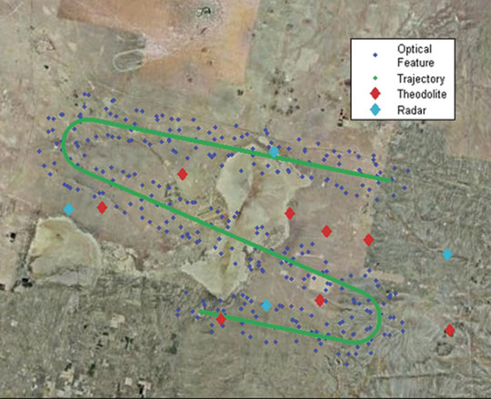
    The fighter aircraft flight discussed here is based on a flight model overlaid on a map of the Fort Worth, Texas, area (FIGURE 1).

    Figure 1 Simulated tactical fighter aircraft flight trajectory over north Texas
    Figure 1 Simulated tactical fighter aircraft flight trajectory over north Texas

    Mod/Sim Process


    Before discussing the simulation results, it’s important to understand modeling and data analysis in its proper context. Disciplined performance analysis is like the scientific method — it begins before the test is initiated and concludes by validating preliminary assumptions using results of the experiment.

    Analysis of military navigation system performance begins with software modeling as shown in FIGURE 2, first panel. In this example, software tools predicted, among other things, SV carrier-to-noise values; azimuth and elevation angles; constellation dilution of precision (DOP) values; and GPS receiver acquisition/tracking performance. If required, software may also predict jammer-to-signal (J/S) ratios at the weapon GPS antenna.

    Figure 2 Navigation system performance analysis
    Figure 2 Navigation system performance analysis

    The next step (second panel in Figure 2) enhances software models with hardware-in-the-loop (HWIL) simulations, replacing predictions with actual performance data. Conclusions from RF and computer simulation stage will often aid significantly in field-test set-up. Benefits of simulation include isolating design flaws, validating algorithm performance, and exercising the GPS/INS system with realistic and stressful inputs. These activities may reduce the number of flight trials required, which in turn reduces the potential for program cost and schedule slips.

    Modeling Results


    FIGURES 3 AND 4 show predicted results from the commercially available Navigation Tool Kit (NavTK) regarding the navigation performance of the unaided GPS receiver within the fighter aircraft during its highly dynamic flight. STK generated the 6-degree-of-freedom (6-DOF) trajectory used in this test. This trajectory is based on the dynamic limits of the aircraft; representative roll/pitch/yaw rates; typical climbing; cruising and descent speeds; takeoff and landing distances, and so on. This data was subsequently passed to NavTK. Figure 3 shows number of satellites tracked throughout the flight while Figure 4 predicts East-North-Up errors given actual GPS performance (clock data, ephemeris data, and system performance) for July 1, 2005. This detail is possible because NavTK can accept archived GPS constellation data from the GPS Operations Center (GPSOC) to fully represent the effects of geometry, satellite health, ephemeris errors, and clock variations for individual SV signals.

    rder=”0″ align=”left” class=”content_image” src=”/files/gpsworld/nodes/2006/6535/i4_t.jpg” alt=”Figure 3 Number of signals tracked” />
    Figure 3 Number of signals tracked

    Figure 3 highlights flight portions when loss of lock is expected due to platform orientation and accelerations. When the aircraft initiates a steep turn, the accelerations cause cycle slips that result in loss of lock. These results are useful for isolating discrete periods of time during which performance of the INS-only solution can be scrutinized during hardware simulation. At these times the INS navigation filter relies exclusively on ΔV and Δθ terms from the inertial simulator to compute a fix.

    Figure 4 Predicted navigation errors
    Figure 4 Predicted navigation errors

    When PRN 25 disappears below the horizon approximately 25 minutes into the flight, we see a noticeable shift in predicted accuracy. This suggests that DOP values may worsen noticeably at this point, or that clock/ephemeris errors for this satellite had a noticeable effect on the GPS-only solution. These results depend on inputs provided for the receiver models, constellation behavior and tracking loop algorithms, and provide a start point for pre-HWIL evaluation. Again, results from this modeling exercise highlight a unique moment in time in which the performance of the GPS/INS navigation filter can be tested with a hardware simulator.

    Software modeling tools can also provide valuable inputs to the simulation process with trajectory modeling. STK can create flight simulations for military applications including missiles, rockets, spacecraft, and airborne platforms. In this example, software created a 6-DOF fighter trajectory which was stored as a file on a SimGEN PC.

    GPS/INS Simulation


    HWIL GPS/INS simulation of many military flight trajectories consists of generating a composite GPS RF signal synchronized with inertial ΔV and Δθ terms. Precise synchronization is achieved via a 1 PPS interface between the RF signal generator and the inertial simulator PC. Latency of the IMU motion data is also specified in microseconds. Together, these RF and inertial inputs are delivered to the navigation system under test.

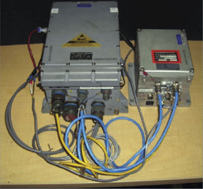
    FIGURE 5 illustrates the GPS/INS test equipment in more detail. Platform dynamic motion (in this case from STK), GPS constellation data, signal parameters, and GPS/INS error sources are defined within the simulation application (SimGEN). Signal control commands are issued continually from the simulator PC to the RF signal generator via IEEE-488 (GPIB). The RF signal is typically connected to the GPS receiver antenna port via coaxial cable. INS ΔV and Δθ terms are calculated to the vehicle trajectory on a separate PC (SimINERTIAL) and are delivered to the GPS/INS device in test mode via the appropriate interface. The SimINERTIAL PC and signal generator are synchronized via a 1 PPS signal. Barometric altimeter aiding and instrumentation are achieved via MIL-STD-1553B.

    Figure 5 GPS/INS simulation block diagram
    Figure 5 GPS/INS simulation block diagram

    Realistic simulation requires many unique components of the navigation solution to be carefully specified in advance. These include but are not limited to:

    • 1. Trajectory
    • 2. Antenna pattern
    • 3. Constellation geometry
    • 4. Codes and frequencies
    • 5. G-sensitivity
    • 6. Gyro and accelerometer errors
    • 7. Atmospheric effects
    • 8. Multipath
    • 9. Interference


    Trajectory. As mentioned earlier, a flight trajectory is usually expressed as a series of time-stamped translational and rotational motion terms. Rotational motion is typically described by Euler angles or quaternions. The GPS/INS simulator uses this trajectory as the basis for calculating SV pseudoranges, Doppler values, and inertial delta-V and delta-q terms. This flight trajectory can be delivered to the simulator remotely via a high-bandwidth interface such as IEEE-488, SCRAMnet or TCP/IP, or, as in this example, may reside as a file on the simulator PC hard drive. Flight times may range from a few minutes to several hours or even days.

    For this simulation, the 45-minute flight over Fort Worth includes take-off, landing, and several steeply banked high-g turns. The airspeed for the majority of the flight is approximately 500 mph.

    Antenna Pattern. If the simulator’s RF signal is injected directly into the antenna port of the GPS/INS system under test, the gain and phase characteristics of the receive antenna must be modeled. For best results, the effects of the body on which the antenna is mounted must be included. Gain and phase pattern measurements are typically collected in an anechoic chamber or outdoor range and are generally available to test engineers evaluating GPS/INS system performance.

    Constellation Geometry. A simulated flight can occur at any time or location to test the effects of constellation geometry on the navigation solution. Historical GPS almanac information is available from the GPSOC and can be loaded into the simulation scenario. This example used historical almanac parameters from July 1, 2005.

    Codes and Frequencies. Most U.S. military GPS/INS systems operate at both L1 and L2 frequencies and track the encrypted P(Y) and unencrypted C/A codes. Future military receivers will also track the M-code on L1 and L2. To fully evaluate unique features of the weapon navigation system including direct-Y acquisition, SAASM functions, and resistance to interference, the simulator must support all modes of classified and unclassified operation.

    G-Sensitivity. Acceleration force can alter the performance of a crystal oscillator. Specifically, changes to the local acceleration vector stemming from high-g maneuvers will change the output frequency of the oscillator. Airframe vibrations may cause frequency modulations of the oscillator output that affect the performance of the tracking loops. To a certain extent, the effects of these forces on the code- and carrier-signal offsets can be modeled. For this scenario, the oscillator G-sensitivity is specified as 2 × 10-11 sec/sec/G per axis, typical for a military-grade oven-controlled crystal oscillator (OCXO).

    Gyro and Accelerometer Errors. Note that GPS/INS simulation does not test the performance of the sensor elements themselves; this exercise is generally conducted with mechanical spin tables or centrifuges. Rather, military INS manufacturers typically include a test interface that allows simulated motion terms to be directly injected into the navigation system. This allows test engineers to evaluate the performance of the Kalman filter during high-dynamic or stressed conditions. For one manufacturer’s system, this in
    terface is proprietary to the Inertial Sensor/Recorder Simulator (ISRS-2); another’s systems accept these test inputs via RS-422. A non-proprietary inertial interface known as NATO Standard Agreement (STANAG) 4572 also accepts simulated ΔV and Δθ terms via RS-422.

    Embedded gyro and accelerometer sensors are imperfect and are subject to a variety of errors. Stochastic errors may be modeled by random walk or by a Gauss-Markov noise estimator, while deterministic errors such as biasing, axis misalignment, and scale- factor errors should also be specified. For this simulation, a second-order Gauss-Markov model is used as described in STANAG 4572 for gyros and accelerometers with unique values for the natural frequency, damping factor, and power spectral density.

    Atmospheric Effects. After Selective Availability was set to zero in May 2000, the primary contributor to GPS ranging error remains ionospheric delay. Dual-frequency receivers can effectively eliminate this effect by processing both carriers, but range measurements at L1 and L2 are still subject to multipath errors. Furthermore, ionospheric scintillation is a complex phenomenon that can affect the tracking performance of dual-frequency receivers. This simulation specifies the historical broadcast Klobuchar coefficients for July 1, 2005, and modifies the SV code and carrier offsets to approximate the effects of the ionosphere for the time, date, and location of the scenario.

    Tropospheric delay varies by latitude and elevation angle and is a function of temperature, humidity, and atmospheric pressure. For more realistic results, the effects of this ranging error can also be simulated. For this simulated flight over Texas the surface refractivity index is set to 324.8.

    Multipath. While the aerial environment is generally free of the same satellite obscuration effects more common on the ground, signals may still be reflected off wings, stabilizers, and flight control surfaces. These path delays affect the performance of the GPS receiver correlators and may introduce position and velocity errors into the navigation solution. GPS simulation allows the tester to specify reflective effects including fixed-delay multipath, Doppler multipath, and vertical plane multipath on a per-satellite basis.

    Interference. Over the last 10 years a variety of techniques have been developed to mitigate the effects of intentional interference on military navigation systems. Adaptive antenna arrays may steer nulls in the direction of jammers or beams in the direction of satellites. Spectral filtering divides the L1 and L2 bandwidths into discrete bins in which interference can be excised using fast Fourier transform (FFT) techniques. Polarization filters attempt to reject interference from sources that are not right-hand circularly polarized (RCHP). Regardless of the mitigation technique, the performance of antijam GPS systems is generally evaluated in the lab prior to conducting flight tests.

    Simulation allows the tester to specify a variety of interference waveforms including broadband Gaussian noise, continuous wave (CW) and swept-CW, AM, FM, and coherent jammers. The relative signal strength of these sources will vary as a function of the distance between the navigation system under test and the jammer.

    HWIL Simulation Results


    Military navigation engineers are usually interested in the following performance characteristics:

    • 1. Accuracy
    • 2. Availability
    • 3. Resistance to interference


    FIGURE 6 shows example results that can be obtained using this equipment to test INS devices under these simulated highly dynamic test conditions. The results presented here are for illustrative purposes only and show the type of data obtainable to fully characterize the performance of a specific INS under all possible conditions. In this example, latitude (black), longitude (green), and height (blue) errors are plotted separately. Discontinuities in the calculation of latitude and longitude may be observed when high-g turns are initiated. Errors in the height component may correspond to rapid climbs and descents. RMS error for this entire illustrative mission was slightly higher than 16 meters. Again, these results are based on the specific inputs for this simulation. Navigation engineers would need to determine whether similar inputs represent their own flight environment and whether these results will satisfy their operational objectives. In practice, results will vary as a function of simulated gyro/accelerometer errors, oscillator g-sensitivity, pre-flight calibration time, flight dynamics, barometric aiding, and SV visibility.

    Figure 6a INS simulation results: latitude upper left, longitude upper right, height lower left
    Figure 6a INS simulation results: latitude upper left, longitude upper right, height lower left

    As expected, availability of the navigation solution was 100 percent. In contrast to the GPS-only performance modeled in Figure 3, the INS solution used ΔV and Δθ inertial inputs to compute a solution whenever a GPS fix was temporarily unavailable.

    Figure 6B Close-up look at latitude (black), longitude (green) and height errors (blue) from lower right panel
    Figure 6B Close-up look at latitude (black), longitude (green) and height errors (blue) from lower right panel

    Intentional RF interference was not created for this HWIL simulation. However, adding this component to the RF signal is possible with additional equipment, and a similar chart could be created to illustrate the effects of jamming on the INS solution.

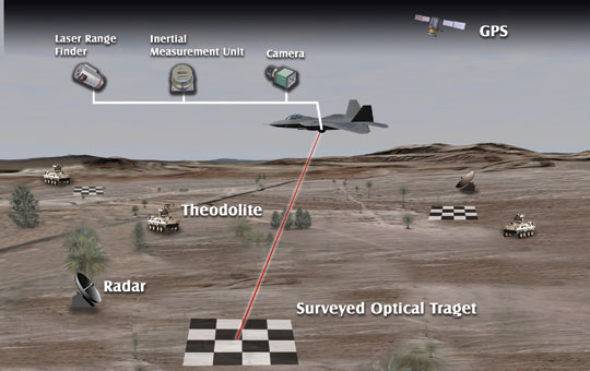
    In addition to this simple error plot, truth data from the GPS/INS SimINERTIAL simulator were also delivered in WGS-84 ECEF coordinates to STK for graphical performance analysis. Time-stamped latitude, longitude, and height data extracted from the military GPS/INS MIL-STD-1553B interface were also provided to STK. Several key performance parameters were then analyzed including carrier-to-noise levels (C/N0), tracking states, pseudorange error per channel, and instantaneous position/velocity errors. FIGURE 7 and the opening graphic compare truth location at a single moment in time as prescribed by the simulator (gray aircraft) versus the actual GPS/INS computed location (color-coded per figure of merit, or FOM). STK can be used to visualize these outputs in real time. Instantaneous position error is projected on the red vector between the aircraft centers of gravity. Vectors pointing toward each SV tracked may be color-coded to J/S, while line type may be selected based on tracking state. Instantaneous pseudorange error for each channel is also provided. Many other data items can also be displayed graphically or in text.
    =”articlecaption”>
    Figure 7 INS simulation results
    Figure 7 INS simulation results


    Conclusion


    Field tests generally provide the most indisputable evidence of military navigation system performance. When a GPS/INS-guided gravity weapon is released above a test range and impacts the ground near its target, we may physically measure the miss distance. We may also assume a similar weapon released at a future time under similar conditions will achieve approximately the same results. But how can we be sure? One approach would be to perform hundreds of trials, if costs and schedules were of no concern.

    However, this is rarely the case. GPS receiver performance models used with the HWIL SimINERTIAL simulator allow the test engineer to minimize flight tests while achieving the same level of confidence. As we have shown, modeling and simulation activities may be tailored for a specific objective — for example, highly dynamic aircraft motion with a fixed satellite constellation geometry while using inertial sensors with known bias and drift characteristics. This simulation may be valuable in conducting analysis of alternatives for different user equipment mixes (receivers, antennas, inertial sensors, platforms, and so on) or to ensure the system meets requirements for all missions.

    Other modeling and simulation objectives may differ from those described in this article. FIGURE 8 enhances our aircraft flight test model to include intentional jamming, an advanced digital antenna, and future modernized GPS space capabilities. Similar enhancements can be added to the RF simulation.

    Figure 8 Real-time 4D data display
    Figure 8 Real-time 4D data display

    Whatever the application, a variety of commercial products allow navigation engineers to prepare for live flight trials on the test range. GPS receiver performance analysis models can be used to create specific GPS/INS simulations that focus on key performance characteristics and environmental challenges. Graphical analysis software can simplify the task of combing through thousands of data records to isolate specific periods during which performance is most important. With careful planning and a disciplined test approach, military and defense industry engineers can use these tools to ensure their weapon systems will deliver at the most critical times on the battlefield.

    Manufacturers


    Analytical Graphics, Inc. developed the Navigation Tool Kit and STK commercial software products used for this simulation. GPS/INS test results were collected using the Spirent GSS7700 simulator with SimINERTIAL.

    CURTIS HAY is director of GPS business development for Spirent Federal Systems. He has master’s degrees in electrical engineering and business administration and served eight years as an officer in the United States Air Force in a variety of GPS-related assignments.

    COLIN FORD is a senior software engineer at Spirent Communications and is the lead architect for the SimINERTIAL navigation test suite.

    GREG GERTEN supports satellite navigation and electronic warfare programs for Analytical Graphics, Inc. He received a master’s degree in electrical engineering from the University of Dayton and has completed graduate courses in GPS at the Air Force Institute of Technology.

  • GPS and Aviation Safety


    U.S. federal agencies, aircraft and avionics manufacturers, airlines, and research centers are brainstorming ways to prevent a repeat of the tragic events of September 11, in which highjacked aircraft were used as missiles. Under these new circumstances, options previously dismissed out of hand suddenly are attracting renewed attention.

    One recurring proposal is to automate the landing of hijacked aircraft. In this scenario, a “dead-man switch” would allow the pilot to turn over navigational control to an on-board GPS-based autolanding system. The system would broadcast a mayday to air traffic control (ATC), search an on-board database for the nearest suitable airport, alert that airport, receive landing authorization, and land the aircraft there. During these operations, no one on board would be able to regain control of the aircraft. The pilot would be like an employee who, when confronted by a robber, does not have the combination to the company’s safe. No amount of violence on board would allow hijackers to use an aircraft as a missile against a target.

    Technologically feasible. The strong consensus of airline, industry, and academic experts interviewed for this article is that the above scenario is technologically feasible. In fact, the autolanding technique has been amply demonstrated and at least one major avionics manufacturer is actively working on producing an emergency landing system.

    The Federal Aviation Administration (FAA) is working on two GPS-based systems that could enable this sort of antihijacking capability: the Wide Area Augmentation System (WAAS) that will enable aircraft to reach the so-called Category 1 decision point in an approach to an airport, and the Local Area Augmentation System (LAAS) that would enable aircraft to reach the ground in zero visibility, known as a Category 3B landing. The agency plans for many airports to be equipped with LAAS transmitters eventually and will require WAAS/LAAS systems on commercial airliners.

    Although both systems still await final certification, testing, and installation at U.S. airports, commercial airliners and military aircraft have already demonstrated fully automatic instrument approach and landing under Category 3B conditions.

    Features

    Although technologically feasible, operational considerations pose obstacles for implementing an automated emergency landing system. The following scenarios address some of these issues as well as technical features of such a system:

    1. A “multiple key” arrangement could restore manual control with codes from the pilot, the co-pilot, and the ground-based ATC operators. Ground control would con- tribute its code only when absolute sure that the aircraft could not be used to attack a population center.
    2. To protect it from being disabled, the system would require a hardened compartment not accessible from the cabin and an autonomous power source not controlled from the cockpit circuit breaker panel.
    3. Prior to landing, the onboard system would notify ATC, which, in turn, would alert and re-route other aircraft as needed.
    4. If the highjackers jammed the GPS signal, the system would put the plane in a holding pattern until it reacquired a clear signal. By refusing to turn off the jammer, terrorists could force the aircraft to run out of fuel and crash – but could not guide it to a target.
    5. According to an industry source, the system should first put the aircraft in a holding pattern in any case, to give a chase plane time to reach it and visually monitor it. In the very unlikely case that the highjackers were able to regain control of the aircraft and aim it toward a target, the chase plane could challenge the aircraft, order it to land, and shoot it down if it did not comply.
    6. The airport database would need to include data on possible flight path obstructions – terrain or tall buildings – so that the system could select a clear approach path. Avionics systems coming onto the market that are designed to prevent controlled flight into terrain essentially have this capability now.
    7. The autolanding system would require permission from the ground to land on a particular runway. If permission were denied for any reason, the system would search its database for the next-best runway.

    Cockpit philosophy. An airline pilot who is now an aide for the operations chief of a major airline reacted very negatively to the idea of an emergency autolanding system that could not be disengaged by the pilot. Any system that restricts the crew’s options, he said, clashes with a key tenet of “cockpit philosophy”: to keep the pilot in charge and never relinquish control of an aircraft completely to automation.

    An emergency autoland system also conflicts with a basic principle of aeronautical engineering – namely, that an aircraft should have multiple, redundant ways to control it.

    However, in extreme emergencies, the alternative may warrant overriding such concerns, according to Bradford Parkinson, a professor emeritus at Stanford University’s School of Engineering who first proposed fully automated cargo planes years ago. He points out that, although an antihijacking system used routinely would have to be extremely reliable, when the alternative is a 100 percent probability of death for all aboard, “Boy, that sure changes the equation in a flash.”

    Further reading: “Soft Landings: Navy Proves Hands-Off Touchdown,” by Matteo Luccio and Glenn Colby, GPS World, August 2001.