Cobham make the anti-jam GPS for the Lynx Wildcat. (Photo: U.K. Ministry of Defense)
Research contract to protect satellite signals from interference
Cobham Aerospace Connectivity will research advanced GNSS anti-jam techniques for the United Kingdom Ministry of Defense (UK-MOD). The research contract was awarded by the Ministry of Defense’s Defence Equipment and Support (DE&S) office.
Under the contract, Cobham will develop means to provide assured and resilient position navigation and timing (PNT) information derived from GNSS. The company has extensive background in advanced antenna technology and sophisticated signal-processing capabilities.
Cobham makes the conformal GPS CRPA for the Eurofighter Typhoon. (Photo: Cobham)
The research is set against a backdrop of increasing reliance on GNSS navigation signals in the nation’s critical infrastructure and national security and the frequent interruptions of the signals either accidentally or intentionally. The more sophisticated interruptions involve the falsification of the navigation signal information for nefarious reasons such as piracy, civil disruption and military advantage.
Cobham’s goal is to take already-developed anti-jam capability and develop a miniaturized system that can provide an advanced means of protection of the navigation signals received from the GNSS multi-constellation network.
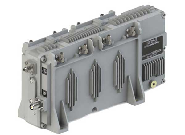
Cobham beam-forming anti-jam GNSS digital antenna control unit. (Photo: Cobham)
The anti-jam system will combine the use of advanced controlled radiation pattern array (CRPA) antenna technology with intelligent digital signal-processing techniques. It will be designed to ensure reliable and assured navigation information, as well as derive important signal intelligence and domain-awareness information regarding the source and nature of the interference and the best means of mitigation.
“This contract award recognises Cobham’s status as a major UK provider of anti-jam systems as well as our long history and deep experience in the areas of navigation antennas and satellite connectivity,” said Neil Tomlinson, vice president of Sales and Business Development at Cobham. “We look forward to working with DE&S in this initial phase and subsequent work on this exciting project.”
What are the key technical criteria in matching GNSS receivers and antennas from the same or different manufacturers? For what uses does it matter most?
John Fisher. (Photo: Orolia)
“For fixed-pattern antennas, it’s fairly simple: RF + DC to power the antenna. Most vendors are compatible. The challenge is more for controlled radiation pattern antennas (CRPA). Power requirements vary greatly, and performance can be improved with a two-way data exchange between the CRPA and receiver, but there is no industry standard yet for this interface. An example: tilt angles from the receiver’s IMU can greatly aid beam pointing.” John Fischer Orolia
Ellen Hall
“Antenna selection is exceptionally critical for our military and high-precision users. The platform and environment are the primary drivers of these antenna requirements. In general, SWaP (size, weight and power) is at the forefront of all criteria. As operational plans are developed, requirements for a single or multi-element array, element gain, and noise figure must be considered.” Ellen Hall Spirent Federal Systems
Members of the EAB
Tony Agresta Nearmap
Miguel Amor Hexagon Positioning Intelligence
Thibault Bonnevie SBG Systems
Alison Brown NAVSYS Corporation
Ismael Colomina GeoNumerics
Clem Driscoll C.J. Driscoll & Associates
John Fischer Orolia
Ellen Hall Spirent Federal Systems
Jules McNeff Overlook Systems Technologies, Inc.
Terry Moore University of Nottingham
Bradford W. Parkinson Stanford Center for Position, Navigation and Time
By Tony Murfin GPS World Professional OEM Contributing Editor
In today’s world where local conflicts can spill over into many other places, it’s become common to encounter GPS signal jamming. Even in locations that defense forces might have considered “backwater” in terms of technology, enemies can apparently launch attack drones, jam adjacent countries, and generally render GPS, if not GNSS, useless for navigation.
The U.S. military came up with anti-jam technology to counter foreseen jamming scenarios several decades ago, but the initial seven-element controlled radiation pattern antenna (CRPA) designs were bulky and required multiple RF antenna cable connections to large, remote receiver processor units. These units not only processed the signals to derive position, but also eliminated jammer and satellite signals in the direction from which the jamming signal was received (null processing). Most of these early units were large and power hungry, so their application was limited to larger aircraft and ships.
Anti-jam technology has gradually evolved over time. Component integration and miniaturization has enabled CRPA performance to be self-contained within the antenna enclosure. At least one design has now migrated the null-processing into the same enclosure as the CRPA antenna, and is sold on a commercial basis to several military forces around the world. The device outputs a single composite RF signal that has been cleaned of any detected jamming signals for use by both commercial and military remote receivers alike.
Now Quantum Reversal (QR) — a new company based in Calgary, Alberta, Canada — has come up with a novel design that processes the CRPA signal in the RF domain, eliminating the need for extensive null-processing electronics. Without these signal-processing electronics, power requirements are reduced from about 15–30 watts to around 1 watt, the size is smaller (4 inches in diameter versus the nominal 6–8 inches in diameter), and cost is significantly lower. These reductions might allow this new anti-jam technology to move into small unmanned aerial vehicle (UAV) applications, timing networks, and reference monitoring networks where continuous uninterrupted GPS/GNSS service is mandatory.
This antenna is designed to enable continuous navigation using GPS or GNSS signals in the presence of unintentional low- to medium-power interference signals. It should be able to reduce the power of an unintentional interference or jamming signal by 35–45 dB, depending on whether it contains three or four CRPA antenna elements.
Increasing the number of antenna elements of the QR design improves the null depth (on average 8–10 dB per antenna element) at the expense of increased circuit complexity, power consumption and antenna size. An average null depth of –70 dB may be possible with a seven-element CRPA antenna. (Image: Quantum Reversal)
This tongue-in-cheek photo, courtesy of Racelogic, underlines how simulators help GNSS engineers “road test” multiple positioning products in multiple scenarios. (Photo: Racelogic)
The number of GNSS signals, the frequency and sophistication of intentional and unintentional threats to those signals, and the need for integration between GNSS and other positioning, navigation and timing (PNT) sources — especially for indoor and autonomous navigation — are continuing to increase, as is the number of new applications for GNSS. In response, manufacturers of GNSS simulators are creating new and improved models able to simulate all these new signals and scenarios.
Additionally, as GNSS chipsets continue to be further commoditized, simulator manufacturers must address the needs of new entrants into the GNSS receiver market that have lower accuracy requirements and require less technical expertise and, therefore, require units that are smaller and cheaper and have simpler interfaces.
No single manufacturer can address the full spectrum of challenges that these trends present. So, while their products overlap in capabilities and SWaP-C (size, weight, power and cost), each one has chosen its market niche and preferred mix of features.
Even on the deceptively simple question of definition (“What is a GNSS simulator?”), the seven manufacturers featured here give different answers, covering the following capabilities:
Simulating GNSS signals as well as inertial navigation data.
Enabling users to test hardware, software and new solutions in the lab before deployment.
Enabling users to test systems under pristine or extreme conditions, including error conditions.
Enabling users to test systems during rare, transitional and prohibited events.
Helping to retrofit existing equipment to new and emerging standards.
Innovations being introduced or developed include:
an anechoic simulator to test continuous radiation pattern antennas (CRPAs).
simulation of a full M-code modernized signal.
software-defined simulators.
increased automation of repetitive tasks.
the capability to record and replay real-world signals.
the capability to record and synchronize data on the conditions faced by a test vehicle.
While the universe of GNSS satellites and receivers continues to grow and evolve, the universe of GNSS simulators is keeping pace — or even a step ahead.
Click on the company to be directed to that section.
John F. Clark, Vice President, Engineering. (Photo: CAST Navigation)
In the lab, simulators allow users to “drive” a piece of equipment through 3D space, performing flight testing or checking equipment integration. Simulators also validate operational flight programs (OFPs) for pilots before they are fielded, to ensure that the software is working correctly.
Innovation. CAST’s latest simulator is the CAST 5000 wavefront generator. It allows users to drive GNSS and interference signals that represent a continuous radiation pattern antenna (CRPA), which consists of multiple, smaller antennas all combined into one unit. In real life, each one of those antenna elements is in a different location; therefore, when they receive signals from a jammer or any of the GNSS satellites, each one will see that signal in a slightly different phase from the other elements. “Our simulator allows us to present signals to these antennas that model the same type of phase differentiation that you see in real life,” Clark said.
Photo: CAST Navigation
Coming Next. CAST Navigation is constantly improving its software based on user feedback. “We are in the process of enhancing our user interface to make it much more powerful but also much simpler to use,” Clark said. Hardware is also being improved, with implementation of the latest available GNSS always on the list.
Looking Ahead to 2022. Jamming and spoofing are becoming more prevalent, not just for the military but also for consumers. Consumers are starting to encounter more instances of jamming, denying their phone the ability to track a GPS satellite or transmitting incorrect GPS data so the solution that their device gives them is not correct. “Our focus is on products and capabilities that help our customers simulate those types of environments and mitigate those kinds of reactions,” Clark said.
Jackson Labs Technologies Inc.
Said Jackson, President and CTO. (Photo: Jackson Labs)
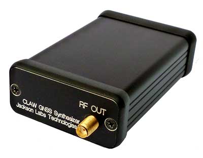
Jackson Labs’ simulators take a position, navigation or timing signal, re-encode it into an RF signal through a GPS simulation procedure, and output a real-time RF signal that encodes the position, navigation and timing (PNT) information, within milliseconds, into an RF signal that can be fed into existing equipment. “We came up with a general-purpose simulator that is basically a no-frills, low-cost, highly accurate, highly stable, highly reliable, extremely small GPS-only simulator,” explained Jackson. “We only provide GPS L1 simulation, to keep the cost of the product down, because GPS L1 C/A code is the only code required to generate an accurate and assured PNT fix, and because we are looking at simulating to embedded systems, where you only need an L1 C/A code simulator.”
Photo: Jackson Labs
Coming Next. Jackson Labs’ simulators don’t require an external computer for data processing or control. That makes it possible for companies like Toyota to plug the unit into a car on the assembly line, and generate RF output that is fed into their GPS-based navigation systems to pass final quality-assurance checks on the production line. Jackson Labs expects to further reduce SWaP-C (size, weight, power and cost) requirements and potentially add other signals. “We are also looking to potentially combine our simulators with other product lines that we have, such as our comprehensive atomic clock product line,” Jackson said.
Looking Ahead to 2022. Jackson predicts that the sector will split into two paths: an industrial sector with units for manufacturing and deployment, and companies that introduce emerging GNSS systems at much lower price points, smaller SWaP, and with more modular deployment. Inertial navigation systems (INS) are critical for autonomous driving and assured capabilities during spoofing and jamming events, Jackson said. “It is not possible today to very easily simulate INS units.There is a market for innovation in terms of integrating what the military calls ‘assured PNT,’ which includes things like dual navigation.”
Orolia
Stéphane Hamel, Director, Testing and Simulation. (Photo: Orolia)
According to Orolia’s Hamel, a simulator’s purpose is two-fold: first, it must reproduce threats and second, it must prove the solution is working.
Innovation. When Skydel Solutions joined Orolia in March, it brought a professional software-defined simulator that makes possible fast prototyping and development cycles. It integrates advanced interference simulation and can simulate hundreds of threats simultaneously. “When you want to do a repetitive step, automation is the key,” Hamel said. “Our simulator can teach you how to automate, just by clicking on a button and generating source code.” In 2018, Skydel introduced an anechoic simulator to test Controlled reception pattern antennas (CRPAs). Also new is a waveform simulator, so CRPA units can be tested in a conducted (rather than radiated) way.
Image: Orolia
Coming Next. In the next three years, Orolia is looking at adding Galileo PRS, GPS M-code, or the next-generation signal. “Being software-defined means that we are very flexible and we can allow our partners to develop their own plug-ins,” Hamel said. “They can build custom signals, restricted or modernized signals. Our simulator will take care of the dynamics of the signal and our partners can focus on the characteristics of the signal, or the things that are secret, classified, or if they simply want to protect their IP.”
Looking Ahead to 2022. Resilience to serious spoofing and jamming threats is high on Orolia’s list, as well as ensuring secure or valid positioning, navigation and timing (PNT) in GPS-denied environments. Alternative signals, sensors and increased complexity require a simulator to address all of these. Companies that develop complex proprietary hardware platforms will be challenged to keep up with the increasing complexity. and a software-defined approach will be an advantage.
Racelogic’s first LabSat was a recorder with player — the signals were recorded outside, and then replayed in the lab. Racelogic’s simulators now also provide simulation of the signals using software to generate the signals as though they are being sent by the satellites.
Innovation. In 2018, Racelogic introduced the LabSat wideband, which uses the company’s SatGen software. It records at 56 MHz and up to 6 bits of resolution and streams the data to an internal SSD hard drive. It can also replay real-world simulations or ones generated with SatGen. For the automotive world, it records and replays signals such as CAN, RS232, RS485, IMU and other data channels, synchronizing them at the same time. VBOX allows users to record and replay video with the perfectly synchronized recording made on the LabSat. “You see exactly the kinds of conditions of the test vehicle or person who has been subjected to the test,” Thomas said.
Photo: Spirent
Coming Next. Racelogic is providing wider bandwidth, greater bit depth, and multiple channels in a small battery-powered device that records even more signals, including lidar, EtherCAT (an automotive Ethernet format) and CAN-FD (a faster version of the CAN format). It will be able to synchronize with multiple video cameras instead of just one in high resolution. “It is basically the same as what we are selling, but on steroids, and at a very similar price point,” Thomas said.
Looking Ahead to 2022. With multi-GNSS going mainstream, both chip manufacturers and simulator manufacturers will be challenged by the cost of test equipment. Chip makers need to be able to test the new signals on their production lines, while simulator makers will need to provide devices at a price point and ease of use for customers with less stringent or slightly less technical requirements. “They need a simpler interface and a smaller, cheaper unit,” Thomas said.
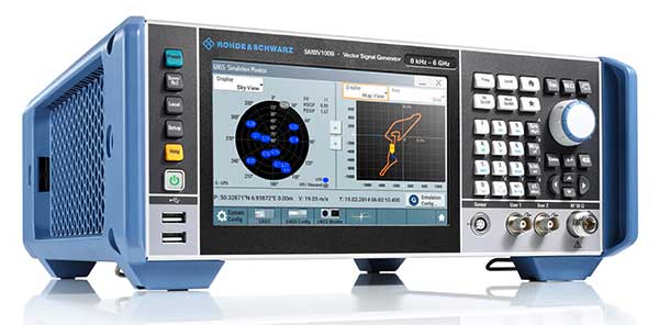
Rohde & Schwarz
Markus Irsigler, Product Manager, Signal Generators. (Photo: Rohde & Schwarz)
An increasing number of GNSS applications depend on multi-frequency GNSS.
Innovation. In response, Rohde & Schwarz added multi-frequency test capabilities to its entry-level and mid-range test solutions. “We have launched a new GNSS simulator based on the new mid-range vector signal generator R&S SMBV100B,” Irsigler said. A simple and flexible option concept allows users to turn the instrument into a full-featured and powerful GNSS signal source. It addresses a wide range of test applications, from single- and multi-frequency production testing to multi-frequency receiver characterization. The instrument can be equipped with an internal noise generator that allows users to simulate GNSS plus noise or CW interference without using additional external hardware.
Photo: Rohde & Schwarz
Coming Next. GNSS test solutions from R&S are based on general-purpose vector signal generators. With this approach, GNSS and other signals can be generated at the same time in the same instrument allowing coexistence and interference testing without additional external signal sources. As this results in test solutions that are compact and very flexible to use, R&S will continue to use this approach for upcoming product upgrades and enhancements as well as for its next generation of GNSS test solutions. The company’s upcoming activities will mainly focus on the high-end segment, where the R&S SMW200A with up to 4 RF outputs and up to 144 channels addresses multi-antenna and multi-vehicle GNSS test applications.
Looking Ahead to 2022. With the safety demands of autonomous driving or aircraft landing procedures, multi-frequency testing will become standard. Because such applications must be sufficiently robust against spoofing and jamming threats, there will be an increasing need to test navigation systems against such influences. “Simulating GNSS alone is not enough,” Irsigler said. “Test solutions for autonomous driving will require several other techniques and signals to be applied or simulated, such as RTK/PPP or outputs from other vehicle sensors to perform sensor fusion.”
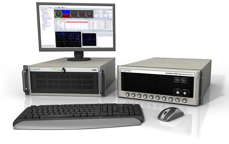
Spirent Federal Systems
Roger Hart, Director of Engineering. (Photo: Spirent)
Spirent’s simulators test with “real-world” signals as well as allowing tests under pristine conditions or under extreme conditions that may never occur in the real world, including error conditions.
Innovation. In December 2018, Spirent released the SimMNSA, which provides a full M-code modernized signal solution. Until now, the GPS Directorate limited M-code simulation to either pseudo-M-code, which provides the same spread-spectrum but uses a commercial encryption standard, or a system of playing back a canned set of M-code limited to certain satellites and dates and times. With the policy change, Spirent can now implement M-code based on the modernized Navstar security algorithm (MNSA), and now offers both an M-code solution with the SimMNSA and a full Y-code with the SimSAAS.
Jeff Martin, Director of Sales. (Photo: Spirent)
Coming Next. Spirent plans to provide customers an increased channel count to help test multi-constellation, multi-frequency receivers against multipath, jamming and spoofing. “We are in a period of intense development in terms of AVs, UAVs, and so forth, which don’t use GNSS exclusively,” Hart said, explaining that Spirent is working on testing of GNSS/sensor-fusion platforms.
Looking Ahead to 2022. “As new interface specifications are released, we are proactive in developing new signals,” Hart said. Spirent also is supporting efforts to achieve assured PNT solutions. It is investigating interference-mitigation techniques such as algorithms, directional antennas, and other anti-jam technologies. Signal authentication is another need. “As the systems are becoming more integrated and networked, we are conscious of cyber-security threats and are looking in that area,” Hart said.
Photo: Spirent
Syntony GNSS
Cyrille Gernot, GNSS Receiver Development and Product Manager. (Photo: Syntony GNSS)
GNSS receiver manufacturers use simulators to ensure that their products are robust in challenging situations that can’t be clearly assessed using real-world data. “That’s where the GNSS simulator comes into play,” Gernot said, “by offering controlled and repeatable scenarios.”
Innovation. Syntony’s new pseudo-random-noise code (PRN code) server allows the GNSS simulator user to dynamically send the pseudo-random sequence modulating a carrier. It is especially useful for testing encrypted signals such as the GPS military signal or the IRNSS RS signal. “Access to encryption keys is extremely difficult for a simulator manufacturer to obtain,” Gernot said. “However, the simulator does not actually need to have knowledge of those encryption keys; only the resulting pseudo-random sequence to modulate is required.” The Syntony PRN server allows users to dynamically input their own pseudo-random sequences to be modulated on the target carrier into the simulator.
Coming Next. Syntony’s next simulator will simulate spoofing and synchronous multi-antenna signals for CRPA and antenna network testing.
Photo: Syntony GNSS
Looking Ahead to 2022. As the threat of spoofing and jamming increases, the receiver industry will have to develop countermeasures and mitigation strategies. One of the best methods remains the use of antenna arrays, Gernot said. “Antenna arrays allow for spatial discrimination that is especially efficient to counter spoofing, jamming or unintentional interferences.To meet the industry’s future demands, Syntony is already working on accurate simulation of antenna arrays while accounting for inherent errors such as inter-antenna phase and amplitude offsets and overcoming obstacles, including phase coherency at the output of the simulator RF channels.”
Dean Kemp, defense segment manager for NovAtel, has joined the speakers’ panel for the June 27 complimentary webinar, Advanced Simulation Test Systems for Controlled Reception Pattern Antennas. He will present unique content alongside Lisa Perdue, simulation product manager for Orolia, and Stéphane Hamel, director of testing at Orolia.
Kemp has over 20 years of academic, industrial and business experience in engineering products and services. He spent a significant part of his career involved in antenna design and development, including controlled reception pattern antennas (CRPAs) for GPS anti-jam systems. As Defense Segment Manager, he is committed to precise, assured positioning and timing to address the needs of Navigation Warfare (NAVWAR) professionals and is dedicated to delivering high-quality products into the defense markets.
He holds a Ph.D. in antennas, radiowave propagation and computational electromagnetics from the University of Liverpool and an MBA from the University of Warwick. Prior to joining NovAtel, he worked at API Technologies, Cobham and Cobham Technical Services. His key technical skills include antenna/RF/microwave engineering, software development (Matlab, Fortran, VBA, Python), data analysis and processing, and test and measurement.
CRPAs are advanced, multi-element antenna solutions designed to protect a GNSS/GPS receiver from jamming sources. When combined with antenna electronics, they form an anti-jam antenna system (AJAS). These systems utilize several available technologies and vary in the number of elements.
This webinar will cover the basics of AJAS and CRPA, and the methods used to test them. Details on simulation system configurations, calibration techniques, and use case examples will also be presented. The webinar is sponsored by Orolia, a global provider of GPS/GNSS and resilient PNT solutions to support military and commercial applications.
Protection from jamming has emerged as the key concern of of both national and organizational/corporate infrastructures. The world abounds in bad actors, and systems based on GNSS signals are uniquely vulnerable. A basic component of any anti-jamming (AJ) strategy is a shielded antenna. An upcoming webinar, June 27, gives a primer and several advanced looks at developing such an antenna-based AJ campaign. Register here for the complimentary webinar.
Anti-jam antennas use techniques, such as nulling or beam-forming, to mitigate the effects of interfering signals. (Image: Orolia)
Controlled reception-pattern antennas (CRPAs) are advanced, multi-element antenna solutions that protect a GNSS/GPS receiver from jamming sources. When combined with antenna electronics, they form an anti-jam antenna system (AJAS). These systems utilize several available technologies and vary in the number of elements.
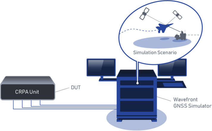
CRPAs will play an increasing role in the GPS/GNSS landscape. Initially developed in the military domain, they are now entering the civilian market and are poised to bring their benefits to the fields of aerospace, ground transportation, autonomous driving and others. Engineers working with GNSS systems that employ CRPAs and multi-element antennas need special test systems since they need to replicate very specific test conditions that are impossible with live signals.
These complex antenna systems require advanced GNSS simulation equipment in order to be designed and validated, as well as to test their performance. These test systems come in two forms — an anechoic chamber system used to test the CRPA antenna over the air, and a wavefront simulator used to test the antenna electronics with a direct cable connection.
Webinar speakers:
Perdue
Lisa Perdue, Product Manager, Orolia. Perdue is an expert in testing critical GPS and GNSS systems. She has trained hundreds of engineers and technicians who are responsible for high-reliability positioning, navigation and timing applications. She took a lead role in the development of the first GNSS Vulnerability Test System and speaks widely on the topic at many industry conferences.
Hamel
Stéphane Hamel, Director, Testing, Orolia. With a career spanning more than 20 years in engineering test and RF, Hamel has developed many innovative and large-scale products to test semiconductor devices, radios and GNSS receivers. In 2014, he founded Skydel, now part of Orolia. Hamel is one of the architects behind the Skydel SDX GNSS simulator.
BroadSim Wavefront Simulator at work. (Image: Talen-X)
Talen-X has added the BroadSim Wavefront Simulator to its software-defined platform.
The BroadSim Wavefront further extends the capabilities achieved by BroadSim Anechoic, incorporating support for controlled radiation pattern antenna (CRPA) and multi-element receiver testing.
BroadSim, powered by Skydel SDX, has brought new innovations to the forefront each year to meet the growing needs of Talen-X’s customers, and the new wavefront simulator is the latest advancement.
Its features include:
Phase-coherent simulation
Real-time automated phase calibration
Scalable from 4 to 16 elements
Advanced jamming and spoofing scenarios.
Talen-X engineers are approaching delivery of an operational demonstration unit, as well.
BroadSense Nano
The BroadSense Nano GPS jamming sensor is the newest addition to Talen-X’s BroadSense product line. It has the smallest size, weight and power of any BroadSense product.
The video below features shows a prototype of the Nano, as well as information about its features and a demonstration of the unit reacting to various jamming waveforms in real time.
In mid-2017, Talen-X and Skydel engineers began to conceptualize a GNSS simulation system emanating from their BroadSim platform for the purpose of fortifying anechoic chambers.
Over the next six months, Talen-X and Skydel designed, built, tested and delivered an anechoic chamber simulator capable of simultaneously generating multi-GNSS jamming and spoofing signals.
BroadSim Anechoic can be used to support a wide variety of operational tests.
“Our new Anechoic Chamber solution will radically change the way in which mission critical platforms and systems are tested because we are enabling our customers to create real-world threats,” said Talen-X Chief Technology Officer Tim Erbes said. “Not only will BroadSim Anechoic be able to emulate real-world threat scenarios, it will be easier than ever before to create and simulate these environments.”
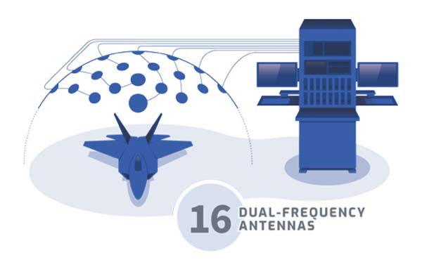
BroadSim Anechoic is used to test GNSS spoofing and jamming in an anechoic chamber. The BroadSim Controller is at the heart of the system running Skydel’s SDX software suite. Using SDX, users can create advanced scenarios that include both jamming and spoofing signals.
The 16 software-defined radios (SDRs) each with dual transmit ports (32 total outputs) can be configured to output GNSS or jamming signals, giving users flexibility to run test after test. The transmit chains include the hardware to power 16 dual-frequency antennas. The included GNSS receivers allow users to monitor the environment inside the chamber, providing confidence that tests are running correctly.
The BroadSim Anechoic can also be used in controlled radiation pattern antenna (CRPA) testing. Many ground-, airborne- and water-based platforms are transitioning to using CRPAs because of their added jamming resiliency and significant tracking advantages in degraded environments.
Validation and real-world testing is critical to understanding and characterizing the mitigation these antennas can add in highly degraded areas. By using BroadSim Anechoic, users have the ability to create representative jammers with real-world characteristics (modulations, frequencies, angles, power levels, etc).
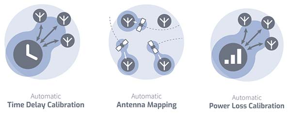
“Skydel developed an innovative approach for time offset calibration between multiple transmitting antenna using a COTS Software-Defined Radio (SDR),” said Skydel Solutions Chief Technology Officer, Iurie Ilie. “This approach allows for very precise measurements and adjustments (better than 100ps) to be done automatically before simulation start. At the same time, transmitting signal power is automatically adjusted to keep the power offset at receiving antenna better than 0.1dB.”
BroadSim Anechoic takes advantage of state-of-the-art software defined radios (SDR) for RF up-converting while signal IQ generation is done using high performance commercial-off-the-shelf (COTS) graphics-processing units (GPU). The ability to generate the IQ data in software (using the GPU) as opposed to hardware (FPGA) significantly reduces the cost while maximizing capability, value, and time to market.
BroadSim Anechoic has the capability of powering up to 16-dual frequency antennas requiring 32 RF transmit outputs. The architecture used for this system required the ability to receive signals in a manner such that precise processing could be done on the receive signal.
The SDR selected for this application has one receiver channel for every transmit channel giving BroadSim Anechoic 32 RF receive ports. Innovative software techniques have been developed enabling the accurate time and power calibration for each antenna transmit chain using the SDR receive ports.
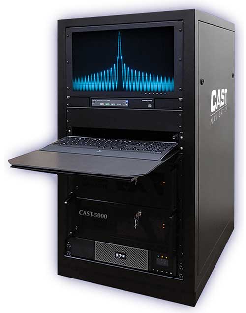
The CAST-5000 by CAST Navigation produces a single coherent wavefront of GPS RF signals to provide repeatable testing in the laboratory environment or anechoic chamber. The system generates up to seven independent, coherent simulations that reference a single point. With an intercard carrier-phase error of less than one centimeter, the CAST-5000 is extremely accurate, the company said.
The system generates a wavefront of GPS when its GPS RF generator cards are operated in a ganged configuration. Each generator card provides a set of GPS satellites coherent with the overall configuration. Several RF generator cards may be utilized together, ensuring phase coherence among the bank of signal generator cards.
The CAST-5000 is the only Controlled Reception Pattern Antenna (CRPA) tester that allows a full end-to-end test of the antenna system. The CRPA antenna, antenna electronics and the GPS receiver can be tested as a unit with or without radiating signals.
CAST-5000 Features
Generates single coherent wavefront of GPS
6 degrees of freedom (DOF) motion generation capability
We’ve heard a lot in the news recently about GPS spoofing, mostly centred on the story of ship spoofing in the Black Sea. Between June 22-24, a number of ships in the Black Sea reported anomalies with their GPS-derived position, and found themselves apparently located at an airport.
What happened is open to educated conjecture. In this column, I’ll briefly cover the history of spoofing, its basic techniques, some spoofing tests that we conducted, and then return to the infamous Black Sea incident.
As part of my day-to-day work in navigation warfare, I do a fair amount of work in defensive anti-spoofing. Naturally, in order to test anti-spoof technology, it is necessary to also perform spoofing. It’s a delicate subject and, as with any topic involving defense or national security or critical infrastructure, there’s a balance to strike between responsible disclosure, how much information is released into the public domain, and so on.
In this article, I will stick firmly to information available in the public domain, lest I be accused of proliferating the threat, but this still gives us enough material to tiptoe around the subject for the benefit of our readers. I could have included more details about the spoofing attacks, but was advised to hold some back — it makes governments nervous. You can read some of the background in an excellent article by Norwegian broadcaster NRK and a Resilient Navigation and Timing Foundation press release. Similar GPS anomalies still continue to occur at various locations.
Let’s start with basic spoofing background, and we’ll return to the Black Sea incident at the end of the article.
A brief history of spoofing
Spoofing isn’t a new threat — it’s been around for decades. But only in recent years has it received so much public attention. As with jamming and anti-jamming technology, and most other topics in the GPS domain, spoofing finds its roots back in the days of Cold War radar. In those times, it was often known as “deception jamming,” where you would transmit fake radar returns to paint an incorrect picture on your adversary’s radar screen.
When GPS came along, it was understood at the time that the C/A code would be vulnerable to spoofing. It’s an open code, so anyone is free to reproduce it. That is, after all, what a GPS simulator is: a GPS spoofer. We legitimately test our GPS receivers by fooling them with fake signals from a GPS simulator.
Of course, this is precisely why legacy GPS satellites also transmit the military P(Y)-code, and continue to do so. The P-code offers improved accuracy, and some other benefits, but more importantly, it is modulated with the W encryption sequence to give us the encrypted P(Y)-code. Ever since the anti-spoofing module was set to the “on” state, unless you have the key, you are unable to directly spoof the P(Y)-code. (You can still perform a meaconing attack, though, where you simply record the transmitted satellite signals and retransmit them again. Although this kind of attack can’t be used to impose a particular scenario on a GPS receiver, it might still cause havoc in unwary receivers).
So. in the early days it can be argued that the spoofing threat was solved. It wasn’t until GPS became ubiquitous in the commercial and civilian domain that spoofing really raised its head again. The fact that the vast majority of GPS receivers in the world relied solely on the unencrypted C/A code became a cause for concern — especially where those GPS receivers were essential to critical infrastructure.
The threat of GPS spoofing was discussed at many conferences and behind many closed doors and, although most people agreed that spoofing was a theoretical threat, some people argued that in reality it was “simply too hard” to conduct a realistic spoofing attack. And therefore we should not worry ourselves about it.
It wasn’t until a couple of high-profile demonstrations were carried out by the University of Texas Radionavigation Laboratory that spoofing became front-page news once again. In 2012, the lab staff carried out an exercise at White Sands Missile Range where a GPS-guided drone was spoofed from a distance. The drone was fooled into thinking its altitude was increasing, causing it to compensate by dropping straight down. Then in 2013, the same team demonstrated how an $80 million yacht could be steered off course by means of a spoofing attack.
These exercises publicly demonstrated that spoofing was indeed a real threat, and could be done. But many people still believed that it was very hard to build the complex equipment necessary to perform the attack, and thus spoofing was out of reach for most potential criminals or terrorists.
Fast forward another two or three years, to when a new mobile phone game appeared. Pokemon GO became the game craze of the moment, where players would travel around the country with their phones, getting points by collecting creatures in an augmented reality world. It didn’t take long for people to dream up new ways of earning points in the game, without having to go to the effort of traveling around the world.
What if you could make your phone think it was somewhere else, without ever having to leave your bedroom? And thus, bizarrely, it was a mobile phone game that brought GPS spoofing into the mainstream.
The rise of the low-cost software-defined radio (SDR) has enabled “spoofing for everyone.” Today, the tool of choice for the casual user is often the HackRF or bladeRF. Couple small SDRs that cost around $200 with open-source GPS simulation software, and you have a basic spoofer. Plenty of websites detail how to perform basic spoofing, and at hacker gatherings, people can present how they spoofed a drone. These may not be the most sophisticated setups, but it’s good enough to do the job in many cases. With a better setup, which I won’t describe here, it’s possible to achieve a much more realistic attack, which will fool even the most shrewd and wary GPS receivers.
Spoofing basics
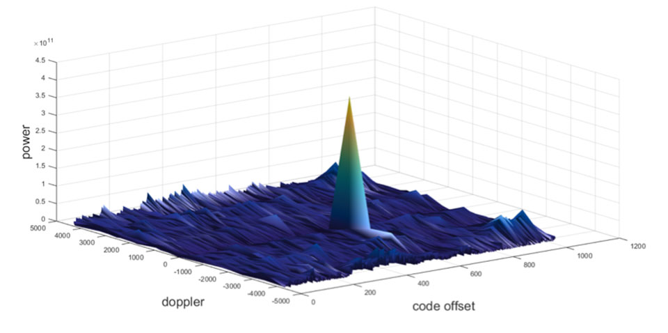
Let’s take a quick look at what it means to spoof GPS. A receiver searches for a satellite over a two-dimensional surface to find a correlation peak, and it must examine a range of Doppler frequencies and code offsets. An example is shown in Figure 1. Once the receiver finds the peak, the satellite is acquired, and it will then track the satellite as it moves and can demodulate the navigation data message.
When a spoofer comes along, it tries to recreate this peak. By doing so, and usually with little more power than the real satellites, the receiver will begin to track the spoofed signal. Once the spoofed signal is being tracked, the spoofer can begin to manipulate reality by slowly modifying the properties of the signal.
Figure 1. GPS correlation surface. (Image: Michael Jones)
A poor spoofer doesn’t always align itself very well with reality, which essentially creates a second peak on the correlation surface. But a gullible receiver can still be fooled by this, and may lock on to false peaks.
The reality of spoofing and anti-spoofing
To understand the reality of spoofing and anti-spoofing, we carried out outdoor experiments at one of the Roke Manor trials areas (thanks go to my colleague Mike Wells for letting me use some of his results here).
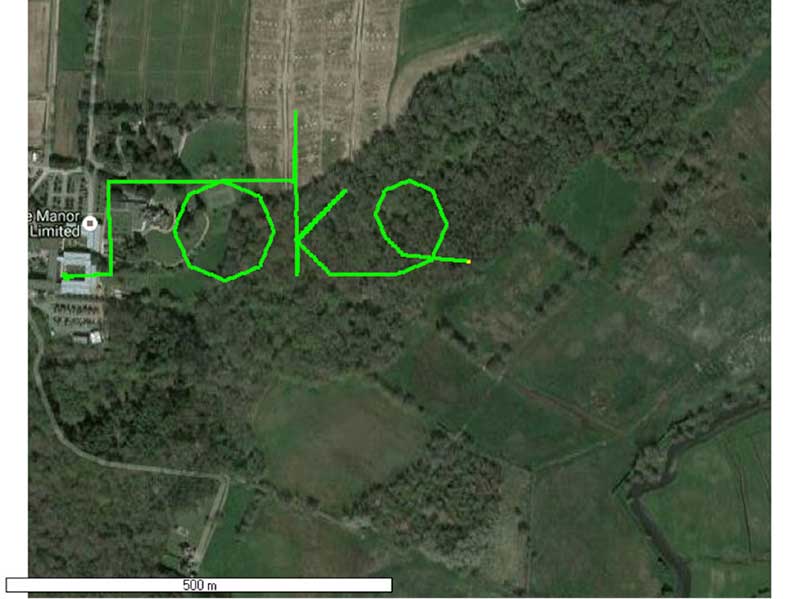
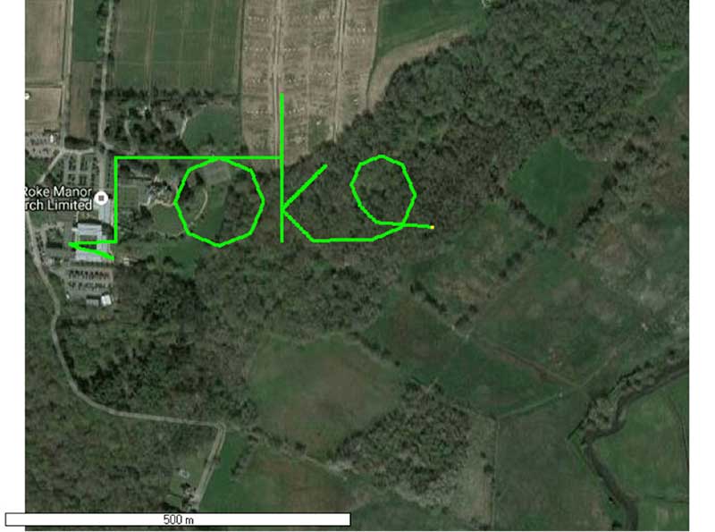
In the first experiment (Figure 2), we spoof a commercially available mass-market receiver. The receiver is outside, reporting its correct location at Roke Manor. When we commence the spoofing attack, we are able to take control of the receiver. Once captured, we can then make the receiver appear to follow an arbitrary course. Here we make it wander off into the forest, spelling the word “roke” as it goes.
Figure 2. Spoofed GPS receiver appears to follow a course, whilst in reality being stationary. (Image: Michael Jones)
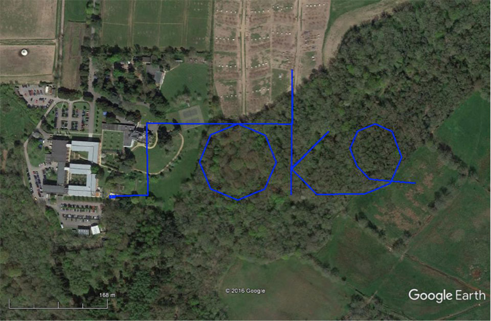
In the next experiment (Figure 3), we place a conventional anti-jam antenna (a CRPA) on the receiver. What we observe, as you might expect, is that the basic CRPA offers no protection against the spoofing attack.
Figure 3. A GPS receiver is still successfully spoofed when protected by a conventional CRPA. (Image: Michael Jones)
Now let’s make the experiment more interesting. We’ll move away from the basic commercial receiver, and replace it with a unit that contains not only a GPS receiver, but also a 3-axis accelerometer, 3-axis gyro, 3-axis magnetometer and a barometric sensor. An Extended Kalman Filter (EKF) performs an optimal fusion of the various sensors to yield the position solution.
The result, when we again try our spoofing attack, is shown in Figure 4. In short, the receiver is still successfully spoofed, despite the additional sensor inputs it offers.
Figure 4. A GPS receiver with integrated inertial sensors is still spoofed. (Image: Michael Jones)
Before everyone gets too depressed by the ease at which GNSS, and even GNSS fused with other sensors, can be spoofed, there are answers to this problem. Some decent, modern GNSS receivers contain a whole host of algorithms for detecting and ignoring spoof signals. The issue is that many legacy receivers are still in the field, and these can be extremely vulnerable indeed.
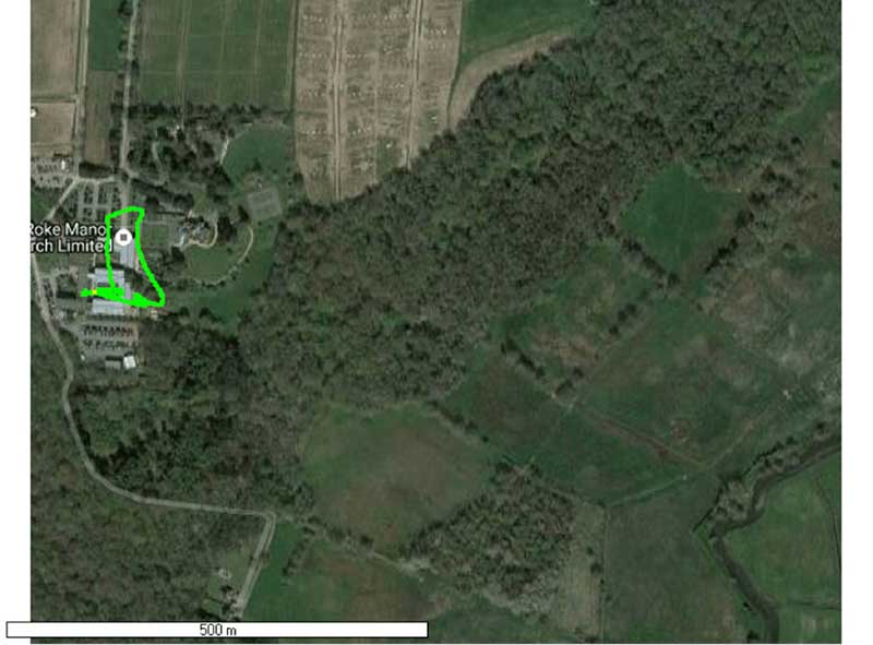
Another option is to use a more advanced CRPA, which offers anti-spoof capabilities. These adaptive antennas are able to correlate on the spoof signals, and then remove them based on direction of arrival. So, in our final experiment here, we use our commercial mass-market receiver again, and protect it with an anti-spoofing CRPA.
The result is shown in Figure 5. You can see that the receiver is briefly spoofed, and starts to wander off course. When the anti-spoof is enabled and kicks in, the position quickly drifts back to the true location and stays there. Good job.
Figure 5. With an anti-spoof CRPA, the GPS receiver detects the spoofer and quickly returns to its true location. (Image: Michael Jones)
Back to the Black Sea
Let’s finish by returning to the hot topic of the day. Did spoofing occur in the Black Sea back in June? Or was it a different form of interference? Could it have been a low-level jamming incident, causing the GPS receivers to report misleading information?
Without resorting to SIGINT (signals intelligence) data, and basing this discussion solely on public domain information and anecdotal evidence, I would say this was almost certainly a spoofing incident. A number of factors lead to this conclusion, and I’ll share some of them.
Firstly, it didn’t happen to one ship – it happened to over 20 separate vessels. So it wasn’t a malfunctioning GPS unit; it was an external incident of some kind.
Secondly, a large number of ships in the area reported identical or very close locations. This is a symptom of a large-scale spoofing attack. If it was a low-level jamming attack, then any misleading positions reported by vessels would typically have some randomness to them.
Thirdly, ships reported that their positions would periodically “jump” from the true location to the incorrect location. Again, this is very typical behavior in some spoofing experiments: For various reasons, GPS receivers may temporarily lose lock on a spoof set of satellites, and then reacquire the real ones, and vice versa. This causes the characteristic random flipping between two well-defined locations.
If we accept that a GPS spoofing attack did occur, it brings us to the million-dollar question.
Who did the spoofing, and why?
What I’ll do here is a bit of a lightweight analysis exercise using public information and basic physics, and you can formulate your own conclusions.
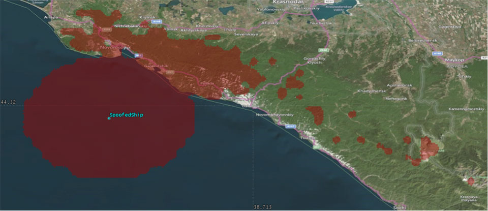
Let’s start by placing a ship, located in the Black Sea at 44°14.0’N 037°43.1E, which is the actual position of one of the reported spoofed vessels. For this example, I have placed a representative GPS antenna on the ship’s mast, with its antenna pattern shown.
Figure 6. Victim ship in the Black Sea, with GPS antenna pattern shown. (Image: Michael Jones)
To get a rough handle on the scenario, consider the possible propagation of the spoofing signal. As a first-order approximation, let’s assume a standard 4/3 Earth refraction model, with obstruction by terrain. That’s a reasonable assumption at this frequency: Any obscuration by terrain will block the spoof signal. Let’s also initially assume that our GPS antenna on the ship is mounted 38 meters above sea level, and our spoofing equipment is mounted on a mast 20 meters aboveground. From this information, we can plot a map of possible spoofer locations for this particular incident (Figure 7).
Figure 7. Possible spoofing source locations. (Image: Michael Jones)
The first thing we might conclude from this is that the spoofing indeed originates from Russian territory, close to the Black Sea coast. To spoof the ship from further afield would require a much higher antenna, or even an airborne antenna. Which, of course, is possible, but then we would also expect vessels over a much wider area to report interference.
To me, it’s fairly conclusive that spoof GPS signals are being transmitted from this area, to make GPS receivers in the area think they are at an airport. The final question is: “Why would someone do this?” To answer this question, we must resort to educated speculation. Why would you want to spoof GPS receivers into thinking they are at an airport?
There’s one explanation that fits very nicely: drone defense. Many drones, especially those operated by casual users, have geofencing rules that prevent flights over airports and other restricted areas. So, if you were trying to perform aerial surveillance of the Russian border, your drone may suddenly think it was over an airport, and take action accordingly. The action taken depends, of course, on how the drone is programmed, but often includes “land immediately” or “return to launch point.” Certainly some of the drones we operate will immediately attempt to land if they find themselves in restricted airspace.
So if your drones are falling into the sea, you now have one idea why.
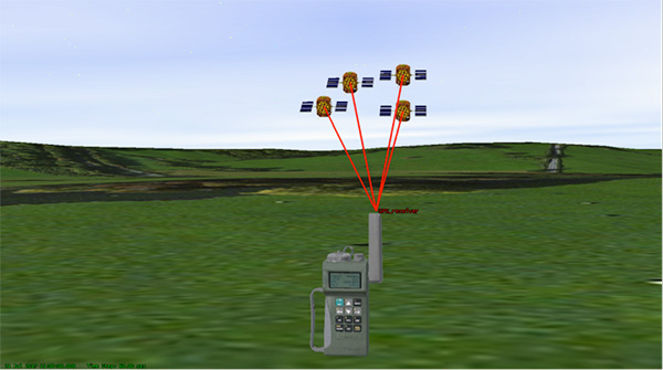
In the battle for reliable positioning and timing, the U.S. Army is engaged in a multitude of activities, including mounted and dismounted A-PNT (assured position, navigation and timing) systems, anti-jam technology and pseudolites.
The idea is simple: Take some GPS satellites, and put them on or near the ground. Now you have a navigation system where you have full control over the locations and power of the transmissions. You can ensure that the transmissions reach places that GPS normally struggles with, such as deep urban canyons, forests and valleys.
You can turn up the transmit power, so they are much harder to jam than spaceborne GPS signals. These pseudo-satellites, commonly referred to as pseudolites, have seen steady interest over the years for a variety of applications.
Now the U.S. Army is pursuing the use of pseudolites as part of its initiative to maintain operation in GPS-denied environments.
Pseudolite Basics
There are various types, and use-cases, of pseudolites. In this column we’ll consider the direct-ranging pseudolite, which can be simply considered as a ground-based GPS satellite. If we deploy several pseudolites on the ground, we can imagine that a normal GPS receiver would be able to receive the GPS-standard transmissions and derive a position, just as we would from the space-based satellite transmissions.
The fact that the pseudolites are ground-based introduces us to the first consideration: The locations of the transmitters are no longer described by orbital parameters. Instead of calculating the position of satellites, we need to describe the location of the pseudolites in geographical terms, perhaps with a fixed position described in Earth-centered, Earth-fixed (ECEF) coordinates.
The transmitted navigation data message, which would normally contain almanac and ephemeris information, may now need to contain the geographical position of the pseudolite. Not a problem, but our GPS receivers will need a software upgrade to be able to handle this situation.
The deployment of the pseudolites themselves poses an interesting problem. Imagine a military scenario, where the army is deployed to a region of interest. Navigation warfare is taking place, and GPS is frequently jammed in the region.
High-power pseudolites are deployed to allow the army to navigate despite the jamming, using the same standard-issue GPS receivers that soldiers are familiar with.
The first problem is, having placed your pseudolites in position, how do you know where they are?
You might choose to place your pseudolites at locations that have previously been surveyed, so you know where they are in advance. But this isn’t likely, particularly if you’ve just moved your troops into an unfamiliar area. You might also want to move the pseudolites regularly, as the army moves to new ground. So the pseudolites need to determine their own position, and the easiest way for at pseudolite to determine its own position is with GPS, of course.
Isn’t this a bit incestuous? If we’re using pseudolites because GPS is jammed, how does the pseudolite get its position? This is why military pseudolites will typically be fitted with some form of anti-jam technology, such as a controlled radiation pattern antenna. This allows the pseudolite to receive GPS satellite signals in the presence of jamming, determine its own position, and transmit that as part of its own navigation message.
So, now that we can get pseudolite locations, the next consideration is: Where should pseudolites be placed?
A-DOP-ting a Good Layout
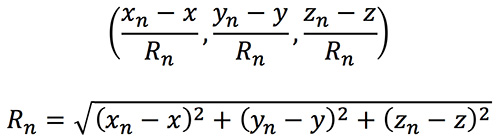
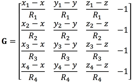
If you know about GNSS, you’ll be familiar with the concept of dilution of precision (DOP). This is essentially a measure of how accurate your position estimate is likely to be, due to the geometry of the satellites: a good wide spread of satellite positions gives us better accuracy.
Figure 1. Poor satellite geometry, resulting in high DOP. (Image: Michael Jones)Figure 2. Good satellite geometry, resulting in low DOP. (Image: Michael Jones)
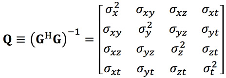
The DOP can be easily calculated by forming a covariance matrix of the geometry, expressed in an appropriate coordinate frame. If (xn, yn, zn) denotes the position of the nth pseudolite, and (x, y, z) the position of the receiver, we can express the unit vectors from the receiver location to the pseudolite location:
We then form a matrix of these unit vectors:
Finally, we form the covariance matrix from which we can extract the DOP values:
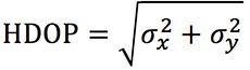
From the elements of this matrix we can determine the various DOP metrics. Let’s concentrate on horizontal DOP (HDOP), given by:
When positioning using GPS satellites, we are blessed with a Walker constellation that generally gives us a nice spread of satellite locations (unless we’re in an urban canyon). On the battlefield, using pseudolites, we do not have the same luxury.
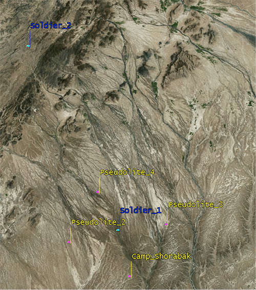
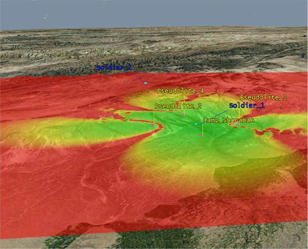
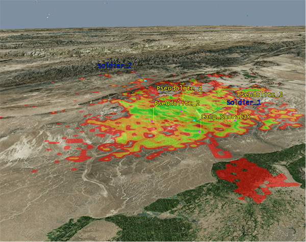
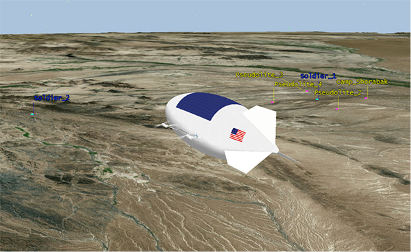
Let’s consider a scenario: a conflict in Helmand province, Afghanistan. An operating base is established at Camp Shorabak, where a pseudolite is operating, and three further pseudolites are deployed in the field. This is shown in figure Figure 3.
Figure 3. Scenario with four pseudolites. (Image: Michael Jones)
Taking a look at Figure 4, we can see what this means for HDOP. The regions shaded green represent locations where our HDOP is less than 2.5, and the red areas represent an HDOP greater than 50.
Soldier #1 is surrounded by the four pseudolites, which is a pretty nice arrangement: We get an HDOP of around 2.4. But if we now consider soldier #2, located a bit further out, we get a very different picture.
Here we have an HDOP of 64, which is fairly terrible. It’s not really that surprising looking at the geometry — to soldier #2 the pseudolites all appear in a similar direction. Soldier #2 cannot expect to achieve good positional accuracy in this arrangement.
Figure 4. HDOP for the Afghanistan scenario. (Image: Michael Jones)
So getting a good geometric spread of ground-based pseudolite locations could be a bit of a challenge, especially if the operating area is constantly moving and changing. The next thing to think about is getting enough height.
Getting the Height Right
When we perform positioning using GPS, we typically track several satellites, which have a range of elevations. Many GPS receivers will choose to ignore the satellites at low elevations, such as those within 5 degrees of horizontal, because those satellites are generally the least reliable. They may be partially obscured, and subject to more noise and fading.
Ground-based pseudolites all have very low elevations by definition. Unless the terrain is perfectly flat and smooth, pseudolites quickly become obscured. Even with flat ground, pseudolite signals will disappear behind the horizon after a few kilometers.
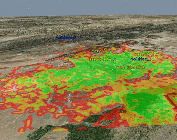
Let’s go back to our Afghanistan scenario again. This time, instead of looking at DOP, let’s look at the geographical coverage of our four pseudolites. Here we’ll assume that our user, the soldier, is 2 meters (m) high, and the pseudolite antennas are mounted at a height of 20m above the ground. That’s pretty high — the army will need to erect some masts.
Figure 5 shows what we get. The green areas are locations where our soldier can see all four pseudolites; yellow three, orange two, and red one. At all other locations, no pseudolite signals can be seen at all. You can quickly see that the range isn’t great — terrain, even small undulations in the ground, is a line-of-sight killer. Add some buildings and trees and the situation gets worse. Reduce the height of our pseudolites below 20m, and the situation gets worse. Soldier #1 can receive three pseudolite signals, but soldier #2 has no hope in this case.
Figure 5. Pseudolite visibility at 20m antenna height. (Image: Michael Jones)
Let’s raise the height of the antennas to a fairly crazy 100m above ground (Figure 6). As expected, we get much better coverage, but soldier #2 still has a problem. To get good signal coverage over any sizable area, you really do need to get those antennas as high as possible.
Figure 6. Pseudolite visibility at 100-m antenna height. (Image: Michael Jones)
Augmenting GPS
Often, we don’t want to rely on pseudolite signals alone. If GPS is available, we clearly want to make use of it, and so we want to use a mixture of both GPS satellites and pseudolites. Consider working in a region of sporadic GPS reception, such as an urban environment or forest. We can usually receive a couple of good GPS satellites, but we also need a couple of pseudolites to help us get a complete navigation solution.
Coming back to one of our original objectives, which is to avoid redesigning the GPS receiver hardware, we need to make sure that our receivers can receive and process both GPS satellite signals and pseudolite signals simultaneously. To achieve this, we can decide to make our pseudolites transmit GPS-standard signals, and make use of unassigned spreading codes to essentially create new satellites in the constellation.
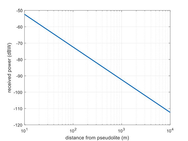
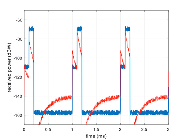
But we quickly run into a problem. GPS satellites are always a distance of around 20,000 kilometers away, and the received signal strength is also fairly constant: around –158.5 dBW. This is a very small signal, as we all know, sitting well below the noise floor. When we suddenly bring high-power pseudolites into the mix, we have quite a nasty problem to deal with.
Near, Far, Wherever You Are
Let’s say, for argument’s sake, we have a pseudolite transmitting with a power of 1 watt. Conducting a basic link budget analysis gives us the plot below and suggests that, at a distance of 10 km from the pseudolite, we can expect to receive the signal at around –112 dBW. This is way above our GPS satellite signal level, but might be manageable by a receiver. Now consider a receiver at a distance of 100 m from the transmitter: we receive a power of –72 dBW, which is huge.
In our quest to augment GPS and make it more robust, we have in fact created a GPS jammer, and achieved exactly the opposite. As with any radio communications link, the received power is extremely sensitive to the distance (varying with the square of distance). In pseudolite terminology, this is known as the near/far problem.
Figure 7. Theoretical received power for a 1-W pseudolite, under ideal conditions. (Figure: Michael Jones)
The near/far problem has given engineers headaches for quite some time. Essentially, the problem comes down to: How can our GPS receivers handle such a massive dynamic range of expected signals? Especially if our objective is to avoid modifying the GPS receiver hardware, if at all possible.
How can a receiver handle the high power of a close-up pseudolite, which is to all intents a jammer, whilst simultaneously receiving the tiny GPS satellite signals from space? Various solutions have been proposed over the years, but one of the current favorite techniques involves pulsing the pseudolite signal.
The idea, then, is to only turn on the pseudolite periodically, essentially applying a duty cycle to the transmission. If a pseudolite isn’t transmitting, it can’t interfere with the normal GPS signals. There are a couple of things to take into consideration here:
What should the pulse duty cycle be, to enable both satellites and pseudolites to be tracked?
How does the GPS receiver behave when presented with alternating large and small signals?
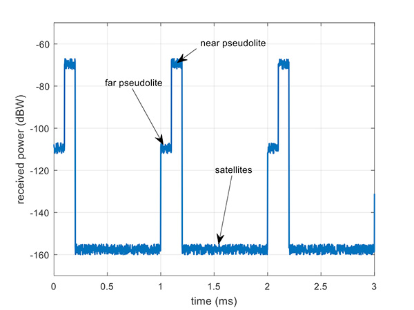
A mathematical analysis of duty cycle effects is beyond the scope of this column, but consider Figure 8 for a qualitative view. Here we have two pseudolites operating alongside GPS satellites. The duty cycle chosen here is for the pseudolite to be operational for 10% of a 1 millisecond integration period. This gives enough time, when the pseudolite is not transmitting, for the low-level GPS satellites to be tracked.
The second pseudolite, which is closer and therefore higher power, transmits for a further 10% slot after the first pseudolite. You can see that each additional pseudolite eats into the time available for tracking GPS satellites, and degrades the signal-to-noise ratio. There are some tricks you can play, such as transmitting multiple pseudolites at the same time if you know they will be similar power levels, but it can get complicated.
Figure 8. Received power versus time, for a pulsed pseudolite scenario. (Figure: Michael Jones)
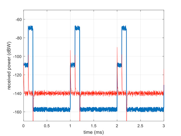
The Importance of Gain Control
How the receiver copes with the large differences in received power level depends largely on the design of the RF front-end in the receiver. Most GPS receivers will have a certain amount of automatic gain control (AGC), which is a feedback loop designed to keep power levels constant. Many GPS receivers, though, simply aren’t designed with enough AGC to handle pseudolite-level signals (think GPS jammers again).
Military receivers, though, tend to have greater RF handling capabilities, and more bits in the ADC, so are better-suited to the situation. It is then a question of making sure the AGC loop responds in an appropriate time, compared to the duty cycle of pulses.
Figure 9 illustrates a slow AGC response, which is not particularly suitable. Compare this with Figure 10, where we have a fast AGC response, quickly adapting to the switches in power level. A receiver with this characteristic will be better able to track both pseudolite and satellite signals.
Figure 9. Pulsed pseudolites with slow AGC response (in red). (Figure: Michael Jones)Figure 10. Pulsed pseudolites with fast AGC response (in red). (Figure: Michael Jones)
Airborne Pseudolites
If you’ve read this far, you’ll now know that the main problems with ground-based pseudolites are lack of good geometry, signal blocking by terrain, and the horrendous near/far issues. Wouldn’t it be nice if we could raise the pseudolites to a really high altitude, and all these problems would go away? Wait, that’s the GPS satellite constellation!
Ok, let’s not put them that far up. But how about carrying pseudolites on high-altitude airborne platforms instead? Great idea, and that’s why this is a current thread of defense activity in various countries. High-altitude long-endurance (HALE) or HAPS (high-altitude pseudo-satellite; the clue is in the name) unmanned platforms can be used to carry pseudolites at high altitude.
This solution can provide excellent coverage, the pseudolites can be repositioned as necessary, and the near/far problem is also far less pronounced.
I leave you once again with our Afghanistan scenario, from the point of view of a high-altitude airship at 18,000 meters.
Figure 11. High-altitude platform, potentially carrying a pseudolite at 18,000 m. (Image: Michael Jones)
The system provides significant immunity to jamming compared with a conventional GPS antenna, allowing the platform to operate over 100 times closer to the jammer whilst maintaining its GPS reception, the company said.
The system will be available to view on Cobham’s stand, hall 2b, stand E156, at the International Paris Air Show, which is taking place June 19-25.
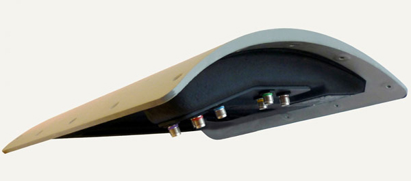
The compact size and modularity of the DACU and CRPA, as well as being receiver independent, means that the system can be installed in land and marine applications. (Photo: Cobham)
“Cobham has been a global leader in development of anti-jam technology for over 20 years, and we are delighted to be launching launch our next generation anti-jam GPS system at Paris Air Show,” said David Bulley, vice president of Cobham Antenna Systems. “The system provides significant immunity to intentional or unintentional jamming compared with a conventional GPS antenna, thereby protecting mission critical systems that require assured position, navigation and timing information from GPS.”
The system consists of a 7-6005 anti-jam GPS digital antenna control unit (DACU) and a four-channel 20-7009 anti-jam GPS controlled reception pattern array (CRPA) antenna. Both units meet stringent airborne requirements making them ideal for new installations and retrofitting to fixed-wing, rotary-wing and UAV platforms.
The compact size and modularity of the DACU and CRPA, as well as being receiver independent, means that the system can also be installed in land and marine applications so offering a single solution for all platforms.
The high-performance, four-channel antenna and electronic system, offers the optimum balance between size, weight, power and cost. Intelligent, dual-band protection is provided with processing optimized to combat the threat environment.