NovAtel’s SPAN GNSS/INS technology is now available on the company’s OEM625S dual-frequency SAASM GPS plus civil RTK receiver. The addition of SPAN offers system developers with SAASM requirements the benefit of continuously available 3D positioning, velocity and attitude (roll, pitch, yaw) for their U.S. Department of Defense (DOD) applications.
Authorized defense customers need access to the Precise Positioning Service (PPS) for DOD applications. When keyed, the existing OEM625S board level receiver provides an RTK PPS solution by taking the raw measurements from an L-3 XFACTOR SAASM and applying them to NovAtel’s industry leading RTK algorithm. SPAN technology couples NovAtel’s precision GNSS receivers with robust IMUs to provide a more reliable, stable solution, even during short periods of time when satellite signals are blocked or unavailable. The company offers a range of IMU options to meet the accuracy and size requirements for nearly any defense application.
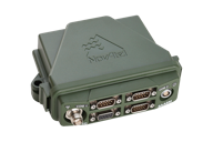
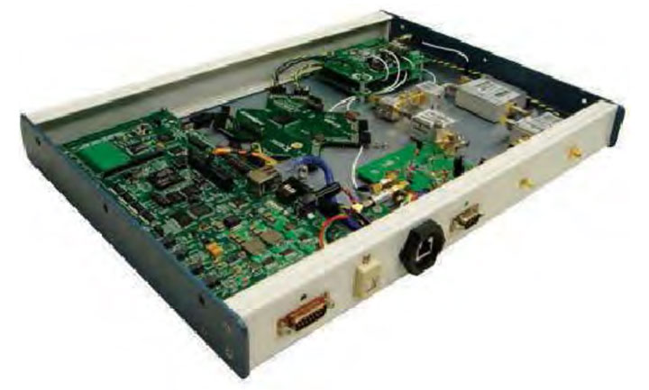
NovAtel’s FlexPak-S enclosure.
SPAN technology is also available on NovAtel’s FlexPak-S enclosure, with multiple RS-232/RS422 serial ports for ease of integration.
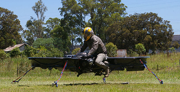
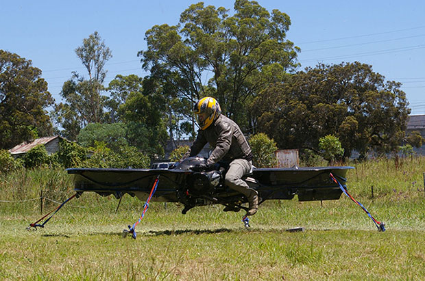
The hoverbike, shown tethered for safety reasons, supports nearly 600 pounds, enough for soldiers and their heavy gear. (Photo: Malloy Aeronautics)
Hover technology has long been depicted in movies like Star Wars and Back to the Future. Now the U.S. Army is teaming up with two companies to develop hoverbike technology — a cross between a motorcycle and a drone.
SURVICE Engineering Co., a Belcamp, Md.-based defense firm, and U.K.-based Malloy Aeronautics, an aeronautical engineering firm, are developing the Hoverbike technology for the U.S. Department of Defense as part of an ongoing research and development contract with the U.S. Army Research Laboratory. The Hoverbike is being developed to operate as a new class of Tactical Reconnaissance Vehicle (TRV).
The makers, Malloy Aeronautics, have a vision for the hoverbike beyond defense. “Its low cost and practical size lends itself to search and rescue, precision farming and cattle mustering, first-responder emergency services and cargo insertion of up to 120 kg (265 lbs) into confined spaces. We believe it would be ideal for ski and mountain rescue, airborne logistics and time-sensitive personnel insertion/extraction during major disasters,” the website says.
As part of this strategic alliance, UK-based Malloy Aeronautics has established a U.S. office in Belcamp adjacent to Aberdeen Proving Ground to complete work on the Hoverbike. A model of the Hoverbike is on display at the Paris Air Show, which runs through June 21.
Malloy’s Drone3, a prototype of the hoverbike, was funded through a kickstarter campaign and is now being sold. According to Malloy’s website, “A Californian customer of ours (Steve Mandel) received his Kickstarter Drone3 in February this year and emailed us yesterday with a photo of his new Drone3 in flight — with a new test pilot.” (Photo courtesy of Steve Mandel)
With about 400 employees, SURVICE is a specialty engineering firm that has been providing R&D support for the U.S. Department of Defense and other industry sectors for more than 30 years.
Formed in 2012, Malloy Aeronautics is an entrepreneurial aerospace company that develops, markets, and sells drones and Hoverbike technology to commercial and military markets.
The video below shows the second-generation Hoverbike in a unmanned static hover. While makers say it’s capable of lifting a person of at least 100 kg, for safety and legal reasons the vehicle is being tested as a drone.
“Establishing an office in Maryland was a clear business decision,” said Chris Malloy, managing director of Malloy Aeronautics. “The proximity to the Army Research Laboratory and U.S. defense decision makers, access to the world-class facilities through the laboratory’s Open Campus initiative, and the co-location with our strategic business partner, SURVICE Engineering, were all factors in favor of Maryland as the best choice for Malloy Aeronautics.”
“Maryland companies do a tremendous amount of research and development (R&D) for the U.S. military,” said Jeff Foulk, SURVICE chief executive officer. “If there is a new military technology being developed, there’s a good chance that some aspect was designed, built or tested in Maryland.”
The U.S. Army Research Laboratory is the nation’s premier laboratory for land forces and is part of the U.S. Army Research, Development and Engineering Command, which has the mission to develop technology and engineering solutions for America’s Soldiers. RDECOM is a major subordinate command of the U.S. Army Materiel Command.
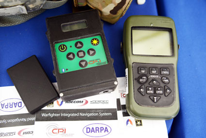
The Warfighter Integrated Navigation System, center, uses inertial systems to determine a Soldier’s location in the absence of a GPS signal. On the left, a smaller version of WINS. On the right, the Defense Advanced GPS Receiver, which soldiers use now for position, navigation, and timing. All three devices were on display at the DOD Lab Day, May 14, at the Pentagon. (Photo: U.S. Army/C. Todd Lopez)
When GPS satellites can’t be seen due to dense jungle canopy, or they are blocked due to enemy interference, soldiers will still be able to track their location digitally using the Warfighter Integrated Navigation System (WINS), a device now under development at the Communications Electronics Research Development and Engineering Center (CERDEC).
During the U.S. Department of Defense Lab Day held May 14 at the Pentagon, CERDEC researcher Osie A. David explained how the technology behind WINS will one day be transitioned to an Army program manager to bring assured navigational capability to soldiers.
The WINS is a device small enough to carry in a soldier’s cargo pocket, about half the size of a pack of cigarettes.
“It’s got a number of inertial sensors, such as a pedometer and an accelerometer, things you will find on your cell phone but of a higher quality,” he said. “Even if the enemy is denying you GPS or the terrain is, you can still get known location on here so it will show up on your Nett Warrior device or your command and control system.” The Nett Warrior is an integrated dismounted situational awareness and mission command system for use by leaders during combat operations, using advanced navigation and information sharing capabilities to allow for faster and more accurate decisions during the tactical fight.
The Nett Warrior
Those inertial sensors will calculate an offset from the last-known location using footsteps taken, speed, acceleration and time, for instance. The device even has way to measure altitude. “It’s got a pressure reader so it knows if you are on the third floor or first floor of a building,” David said.
The WINS isn’t perfect. As time goes by without a new GPS signal, its estimate of current location will degrade. But the device provides for the user an estimate of its own miscalculation. “After a time, it’ll show you a circle radius for the error range,” he said. “It’s still better than having no GPS at all.”
David said knowing location is everything in combat, and the WINS, or a follow-on system that uses technology from WINS, will make sure that soldiers have that no matter what happens to GPS.
“Say we go to Southeast Asia and I’m in the middle of the jungle. There are not a lot of good landmarks. I’m navigating around and I lose the GPS because with the triple-canopy jungle, the GPS can’t penetrate that. I don’t know where I am on the map, so I’m in a bad situation. If I want to know exactly where I am so I can call for reinforcements or resupply, WINS is going to give me my location on a map, no matter where I am.”
David said CERDEC is still working on issues like where soldiers should wear the device. He also said that he expects the engineering specifications for WINS to be transferred to Program Executive Office, Intelligence and Electronic Warfare & Sensors by 2017. It will be inside an Army program manager’s office, not an Army lab, that WINS or the technology it contains will be made available to soldiers.
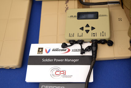
The Soldier Power Manager sits on top of a conformal battery. Allowing multiple devices to be connected to a battery, it reports battery usage, power remaining, and power usage by connected devices. (Photo: U.S. Army/C. Todd Lopez)
David also had with him a device he called the Soldier Power Manager. The power manager was connected to a “conformal battery,” which was also developed at CERDEC in conjunction with industry. The conformal battery is flexible and slips easily into a soldier’s tactical vest without being uncomfortable due to stiffness. It wraps around a soldier’s torso.
The power manager allows multiple devices to connect to a battery, and provides a display saying how much power is left in the battery, what devices are connected to the battery, and how much power each device is using.
“It lets you know how much energy is left and what is plugged in,” David said. He said one advancement the lab has made on the system is to transfer the user interface to a Nett Warrior device, so soldiers can see it on that screen.
“It lets you see the total power left on the device and how much energy each device is pulling, so you can make a decision about what device to pull — when energy gets low — to make sure you have enough power to meet mission needs. We have sort of integrated the energy component with the information to make better choices in the battlefield in terms of operational energy.”
Artist’s concept of the proposed Airborne Swarm Protection Shield over a GDELS armored vehicle (image courtesy of Sky-Watch).
General Dynamics European Land Systems (GDELS) has signed a Memorandum of Interest (MOI) with Danish UAV company Sky-Watch in Støvring, which allows the two companies to explore potential areas of cooperation within next-generation applications of UAV technology in the battlefield.
“Sky-Watch is constantly striving to be at the forefront of the rapidly developing UAV technology,” said Michael Messerschmidt, Sky-Watch chief business development officer. “We offer our vast accumulated know-how within sensor fusion to our partners, in the pursuit of finding new ways to solve tomorrow’s challenges. We constantly rethink and redefine the value proposition, of our own as well as our partners’ ideas and concepts and I believe that we can identify some very exiting avenues of cooperation with General Dynamics European Land Systems.”
Sky-Watch offers the Huginn X1 multi-purpose Quadrotor UAV deployed all over the world and is developing the Muninn X1, a next-generation fixed-Wing VTOL UAV. The future of UAVs in the battlefield will be explored by Sky-Watch Labs, the research and development arm of Sky-Watch, in cooperation with partners such as the Technical University of Denmark on a variety of projects.
With regard to the acquisition of new Armored Personnel Carriers (APC) for the Danish Army, General Dynamics European Land Systems is prepared to take its partnerships with Danish industry to the next level and explore business in adjacent markets like the one of Sky-Watch. GDELS has signed Industry Cooperation agreements with 40 Danish companies of all sizes across the country, and has already defined projects in excess of 3,7 billion kroner covering all of the technology areas defined in the Danish Government’s Defence industry strategy.
“Throughout the past 20 years, GDELS Industry Cooperation program has been one of the catalysts for the development of the Danish defence industry. We have executed projects of almost 1,7 billion kroner with the industry, which has helped to contribute to the development of new products and technologies in a variety of companies. By engaging with an innovative and creative company such as Sky-Watch, we help plant the seed for the future of the Danish defence industry,” said Jens Bauer, GDELS Senior Director International Business & Services, responsible for Industrial Participation.
GDELS’s Industry Cooperation plan for the APC program is based on 20 years of experience and partnership with Danish industry. The program expands relationships beyond production and sustainment contracts to also include research & development projects, which will lay the foundation for growth in the Danish Defence industry for decades to come.
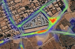
A new report by Visiongainexamines geospatial data analysis for defense and homeland security — a world market worth $9.7 billion in 2014. The report, “Governmental Geospatial Intelligence (GEOINT) Solutions Market 2014-2024: Digital Mapping, Geographic Information Systems (GIS), Cloud-Based Geo-Analytics & Geo-Data Exploitation for Defence & Homeland Security” is being offered by Reportbuyer.com.
Advances in technologies such as cloud and 3D modeling — together with increased availability of high-quality, high-accuracy geospatial data, especially from space-based remote sensing satellites — are propelling the market for governmental GEOINT solutions, Reportbuyer.com said.
“The coming decade will see governments around the world scrambling to acquire GEOINT capabilities on increasingly higher scales, to ensure they stay on top in the ‘information superiority’ race,” Reportbuyer.com said in a press release. “At the moment, outside the U.S. this is a relatively young market, at the very beginning of a period of large international expansion over the next ten years.”
According to Reportbuyer.com, geospatial information exploitation technology is one of the vital enablers and defining aspects of 21st century defense, intelligence and homeland security capabilities and operations. In a digital age where the vast majority of data has a location and time, GIS and GEOINT systems provide the means to reference it geographically.
“In this visual context, complex dynamics, patterns and relationships can be revealed, analyzed and understood in a completely new way,” Reportbuyer.com said. “This takes ‘situational awareness’ to an entirely different level, and enables an unprecedented and powerful new type of analysis: geospatial analysis. A key part of this overall capability is a new generation of tools for advanced digital mapping and modeling, which extend the applications of GIS beyond intelligence, C2 (command and control) and the achievement of information superiority into areas like resource management, mission simulation, and down to individual soldiers.”
The 300-page report provides market forecasts and analysis for GEOINT solutions, 2014-2024, and sales value projections of the market with essential information on the technologies, GEOINT organizations and competitors. The report is available at Reportbuyer.com.
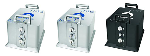
iXBlue unveiled its Marins M series inertial navigation system (INS) at EURONAVAL 2014, held October 27-31 in Paris, France. The series includes the Marins M3, M5 and M7 systems and is designed to address the needs of the world’s most advanced navies for surface-vessel and submarine operations close to shore and in open-sea environments.
Accurate and reliable navigation, including missile alignment, is critical to the success of submarine and surface-vessel missions. The Marins M series raises the bar in performance and scalability by addressing the needs of surface ship navigation under a GPS-denied environment. For submarines, Marins M7 enables three times longer autonomous stealth navigation compared with any available system by offering drifts of less than 1 Nm/72 h.
The Marins M series represents the state of the art in strap-down, fiber-optic gyroscope (FOG) technology, and is combat-ready against GNSS denial, iXBlue said. The military-specification units output position, heading, roll, pitch, depth and velocities, and are perfectly silent. The systems are compatible with a wide range of aiding sensors and can be up and running within minutes.
The extended iXBlue product range, including Quadrans, Octans, Phins and Marins M series systems, now represents even higher scalability of solutions, from attack craft to aircraft carriers and submarines.
More than 30 navies worldwide have selected the iXBlue product range, including previous generations of Marins systems. For example, the UK Royal Navy has adopted advanced iXBlue solutions for its Astute Class submarines.
Abstract submissions are now being accepted for the Institute of Navigation (ION) 2014 Joint Navigation Conference (JNC) to be held June 16-19, 2014.
For Official Use Only (FOUO) U.S.-only sessions will be held June 16-18 at the Renaissance Orlando at SeaWorld, Orlando, Florida; and the 4-EYES CLASSIFIED sessions will be held June 19 at Shades of Green Walt Disney World.
The conference, sponsored by the ION’s Military Division, is the largest U.S. military positioning, navigation and timing conference of the year with joint service and government participation. The event will focus on technical advances in guidance, navigation, and control (GN&C) with emphasis on joint development, test and support of affordable GN&C systems, logistics and integration.
The 2013 Joint Navigation Conference was canceled, so this will be the first time the conference has been held in two years.
From an operational perspective, the conference will also focus on advances in battlefield applications of GPS; critical strengths or weaknesses of fielded navigation devices; warfighter PNT requirements and solutions; and navigation warfare.
The ION JNC features more than 200 operational presentations on a diverse array of topics including:
Advanced Security Technologies/SAASM
Alternate Navigation Technologies: I, II & III
Atomic Clocks and Timing Applications
Autonomous Navigation
Aviation Applications
Battlefield Smart Phone Applications
Celestial Navigation and Star-Tracker Technology
Collaborative Navigation Techniques
GPS Constellation Performance
GPS in Military Applications/NAVWAR
GPS Modernization
Land Applications
Marine Applications
MEMS Inertial Measurement Unit
Micro Navigation Applications
Military GPS Receivers and Military GPS Receiver Technology
Military GPS Use and Experiences
Military GPS/Antenna Technologies and Interference Mitigation
Missile Applications
Modeling and Simulation
Multi-GNSS Receivers for Military Applications
Multi-Sensor Solutions for Guidance, Navigation, and Control
Navigating in Challenged Environments (e.g. Urban, Indoor and
Sub-Surface Navigation)
Precision Azimuth Sensing
Precision Navigation Capabilities for Test and Training
Technical Exhibit and Operational Product Demonstrations. JNC also features a technical exhibit and showcase of Guidance, Navigation and Control technology products and services and Operational Product Demonstrations. For more information on exhibiting and product demonstrations at the ION Joint Navigation Conference, call ION at 703-366-2723 or go to www.ion.org/jnc.
Attendance Restricted. FOUO U.S. ONLY. JNC conference attendance (June 16-19) will be controlled by the Joint Navigation Warfare Center and will be restricted to U.S. ONLY. The classified sessions will have 4-Eyes access (June 19) for citizens of U.S.A., Australia, Canada, and the United Kingdom. All participants must establish a need to know and be approved by the Joint Navigation Warfare Center security office.
Presentation to the 11th Meeting of the PNT Advisory Board
The following is an abbreviated transcript of Don Jewell’s briefing to the PNT Advisory Board at its meeting on Tuesday, May 7. The slides from Jewell’s briefing and the other briefings to the board are available at pnt.gov under the heading 11th PNTAB meeting.
First, a prefatory note from Don Jewell:
Author Sets the Scene
The old adage “A picture is worth a thousand words” certainly applies to the atmosphere of a PNT Advisory Board meeting. And in this case, so does the oft repeated and entirely inadequate phrase “You had to be there.”
The atmosphere of an Advisory Board meeting is extremely dynamic. You have a very distinguished board of PNT subject-matter experts who are very passionate about their areas of expertise. Some, like Drs. Parkinson and Schlesinger, the co-chairs, have been involved with PNT and GPS matters for 45 years or more. Therefore, the danger of an abbreviated transcript of an emotion-filled briefing is always unsatisfactory at best, because you miss the give and take, the repartee of experts that have invested much of their lives in this arena. So it is important that the reader understand the context of the questions and answers and sidebar conversations that took place before, during, and after the briefing, to put it in context.
It would be easy after reading this transcript and others during the meeting to put the blame for antiquated PNT equipment on the manufacturers. But nothing could be farther from the truth. The truth is, the culprits here are numerous but identifiable. They are:
1. Outdated government regulations, directives and procurement/acquisition procedures that seriously hamper equipment manufacturers from doing their best and updating equipment as necessary.
2. Timelines that totally ignore the dynamics of Murphy’s Law — a law of ever-shrinking timelines battling a glacial process of ever-increasing requirements bounded by antiquated procurement procedures and fiscal indecision.
In the case of military user equipment (MUE), the warfighters, first responders, and government users are the unfortunate recipients of this morass of near-pandemonium and downright confusion. Dynamic and critical user requirements are sacrificed upon the altar of “the program of record” and an agonizingly glacial government bureaucracy. Be assured that the “program of record” delivered exactly what was asked for by the original RFP and subsequent contract award.
Take Rockwell Collins for instance. Rockwell is a great company, building rugged, reliable, precision instruments. I have flown with Rockwell communications and aviation equipment in various aircraft cockpits for the last 40 years, and they are indeed the gold standard in that arena. Rockwell has been delivering GPS military user equipment since 1978 and the company has always delivered exactly what was asked for. The problem is that the operational and refresh cycle for government user equipment needs is inside the acquisition cycle, and unfortunately exceeds it by a factor of ten — hence Murphy’s Law.
The Defense Advanced GPS Receiver (DAGR) was an excellent device when conceived and was the only game in town as regards jamming and spoofing environments. I am confident that Rockwell would have continuously updated the DAGR and made it relevant today, given the opportunity, which they were not.
In my opinion, government regulations in the area of user equipment, especially electronics and highly dynamic technological areas, need to be drastically altered to follow the aircraft procurement cycle. For example, there are probably 50 or more different block versions of the F-16 aircraft, that in truth are radically different. In some respects the “Block 1” F-16 resembles the capabilities of the “Block 50” version only in that it is an airborne vehicle with wings, engine, and a fuselage. Electronically and technically, it is a totally different aircraft. But the contracts for General Dynamics and now Lockheed Martin were not recompeted every time the user requirements, and hence the capabilities of the F-16 changed. I hope you all agree that would be ludicrous — and yet that is exactly the situation with MUE. When the scope changes, the contracts are painfully and laboriously recompeted, with lag times that make the process laughable — if indeed it were not so sad.
Then there is the government’s serious lack of information and training concerning MUE devices. I have been around GPS user equipment for 35 years and yet I am sure I still do not understand all the capabilities of the Precision Lightweight GPS Receiver (PLGR) and DAGR. Imagine how befuddled a young warfighter becomes when given the devices and only a cursory amount of training, that is not only inadequate but sadly many times misleading or just flat wrong.
In our interviews we founds trainers — those that taught warfighters how to use the PLGR and DAGR — who were not aware the unit could be “keyed” or encrypted for greater accuracy. Of course we also found excellent trainers, but they were the exception to the rule. Who trains the trainers?
Although it sounds trite and seems to be a copout, don’t blame the equipment manufacturers for the current state of MUE. Blame the system and then get involved and help us change it to what it should be.
Good morning, everyone.
A special thanks to Jim Miller, Dr. James Schlesinger and Dr. Bradford Parkinson for inviting me to speak this morning on the future trends of PNT user equipment, particularly as it pertains to warfighters and first responders — certainly a subject I have been passionate about for only…oh, let’s say about 35 years.
Why GPS World?
Ever since the agenda for the PNT Advisory Board meeting appeared online, I have been receiving emails and phone calls asking why I was speaking not as one of the IDA (Institute for Defense Analyses) subject-matter experts on GPS but as the Contributing Editor for Defense for GPS World. Frankly, the answer is simple. Wearing the GPS World hat gives me the freedom to say what needs to be said today, whereas the IDA think tank attribution and publication rules, which are absolutely necessary for an FFRDC (Federally Funded Research and Development Center) to operate effectively and efficiently, would unduly restrict my comments.
Plus, for 21 years GPS World magazine has been the publisher of the definitive GPS user equipment survey for global users. It’s free for everyone to use, and it covers PNT receiver information from 55 global manufacturers with data on all aspects of 502 PNT receivers. And it is a great boon for me personally, as I only receive on average about 50+ emails or letters per month from users simply wanting to know what GPS/PNT receiver they should purchase. It is wonderful to be able to point them to the GPS World Receiver Survey.
Also wearing my GPS World hat, I can easily refer to the several thousand warfighter and first responder inputs we have received over the last 10 years — generally expressing what they would like to see in a GPS/PNT receiver or sometimes specifically the Perfect Handheld PNT Transceiver (PHPNTT), which I first wrote about six years ago (and most recently in December) in GPS World magazine.
Top 10 Warfighter – First Responder Requirements for the PHPNTT
Adhering strictly to the latest fad in government briefing formats, it is now time for me to BLUF, or give you the Bottom Line Up Front. However, being a journalist, I also have to hold something back for the end. So here are the top 10 PHPNTT requirements, in order of preference, as submitted over the last 10 years by thousands of warfighters and first responders:
Mil-Spec rugged – solid state drive – no moving parts
Friendly, intuitive, familiar interface – easy to use
Multi-GNSS – All signals available – space and terrestrial
SWAP friendly, long battery life, with solar charger
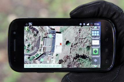
Real-time 3D map data, NGA, Google, satellite imagery
Not a stand-alone PNT device
Embedded in a computer with multiple communication capabilities – one must be secure
Must be able to download, store and utilize new applications
Software-defined and expandable
Act as a sensor with automatic reporting
All these “user requirements” are closely related to what our warfighters and first responders don’t like about the current GPS MUE or Global Positioning System Military User Equipment. I state that specifically because, make no mistake about it, the current MUE is strictly GPS-based. However, the current MUE only receives two of the many signals available today on the GPS SVs, and certainly not any of the other numerous PNT (position, navigation and timing) signals also available, which of course is the crux of the issue for user equipment of the future.
Most of the top 10 requirements, and there were more than 50 requirements identifiable in all, are self-explanatory, and time does not permit me to cover them all in detail. But bear with me for a couple of quick explanations. Certainly the rugged requirement is readily understandable, and there are numerous manufacturers around the globe today that make excellent Mil-Spec rugged devices. However, the one I am most familiar with and have been extremely happy with are the rugged units from Trimble Navigation produced in Corvallis, Oregon. Trimble also happen to be a certified SAASM (Selective Availability and Anti-Spoofing Module) supplier as well. More on those units later.
The second bullet concerns the human-machine interface on the current MUE, which is so poor that a Marine three-star wrote me a few years ago to say that in his opinion, “If anyone wants an example of how not to design an operational equipment interface then they should refer to the PLGR or DAGR. Both are consistently and sufficiently horrendous, in my opinion.” I could not have said it better. The PLGR and DAGR use the gold standard for PNT as a signal, but the human-machine interface (HMI) is, in my opinion and in the opinion of thousands of warfighters, so antiquated and non-user friendly as to be almost unuseable. However, the units do work well and provide outstanding signals when embedded with other equipment. They just do not work well as a handheld device. The other items on the list we will cover as we proceed through the briefing.
GPS MUE Historical Perspective
I have been involved with GPS user equipment for the last 35 years, and this behemoth of a receiver was my first unforgettable encounter.
Yes, this huge device is GPS user equipment. Can you imagine? It weighs more than 300 pounds, without the two operators, and was the very first workable GPS receiver produced for the U.S. military by Rockwell Collins, who has been producing GPS MUEs ever since. Which is an example of the prodigious acquisition issues that also need to be addressed, or corrected, if you will. Our antiquated acquisition practices are to blame for many of the failings in MUE equipment today. While I feel it is critical to mention this as a major contributing factor to the state of MUE today, it is also a story for another time.
Other than being the first GPS MUE, the significance of this huge receiver is that in my estimation it is the first and last time the U.S. military possessed a purpose-built military GPS receiver clearly superior to the products being produced by commercial and civil manufacturers for global users.
First Significant Usable and Transportable GPS Civilian Receiver
Fortunately, a good friend and colleague, both at IDA and ION (Institute of Navigation), Philip Ward, came to the rescue of all GPS users in 1981 when he delivered the TI 4100 NAVSTAR Navigator Multiplex Receiver.
The TI 4100 was indeed the first commercially viable receiver that could be considered a transportable by anything other than an aircraft. To be historically correct, there were some backpack models that were very short-lived and not as significant as the TI 4100. The main unit and two antennas weighed approximately 50 pounds and showed promise in station wagons and helicopters. I can see a few folks in the audience smiling, so I will reiterate that the TI 4100 was a significant milestone, both in SWAP (size, weight and power), accuracy and TTFF (time to first fix). TTFF was 15-20 minutes in search mode, however; after the four SVs were located and the unit was initialized, it could consistently present a fix location in just a couple of minutes. Plus, the TI 4100 was immune from most jamming signals of the day — an impressive receiver and accomplishment for 1981.
Evolution of Commercial GPS/PNT UE
Fast-forward several years and the following picture presents a view of how quickly GPS UE developed.
The first unit on the right in the above photo is a Trimble unit that was about the same size as the TI 4100, but considerably more capable. As you follow the units around counter clockwise, you will see that they decrease in size and weight, but what you can’t see is that they also increase incredibly where acquisition and processing speed (TTFF), accuracy and capability are concerned. Note also that you start to see stand-alone units that appear to be antennas with separate handheld display units. This is a feature the commercial manufacturers incorporated over 20 years ago, and in some respects a feature the MUE manufacturers and services are just now considering.
Note also the Garmin GPS wrist receiver (right), which until 2005 was the most prevalent civil receiver in both of the wartime AORs (Area of Responsibility). Compare this Garmin wrist unit to the 300-pound Rockwell Collins unit I first showed you and consider that where SWAP and performance are concerned, the wrist unit is hundreds of times more capable and portable.
Current MUE – Program of Record and the Future
The pictures below depict the current MUE – Program of Record equipment, again both manufactured by, you guessed it, Rockwell Collins. First is the PLGR or the Precision Lightweight GPS Receiver. Second is the DAGR or Defense Advanced GPS Receiver. The third unit, known simply as the “Puck,” is what the U.S. Army would like to field in the next couple of years along with that separate display unit I spoke of earlier. Starting to sound very commercial, right? By the way, the Puck measures only 2 x 2 x 1/2 inches and weighs just a few ounces.
Between the PLGR, which was decertified by the Marine Corps in 2010, and the DAGR, there are approximately 500,000 of these MUE devices fielded today, and yet almost none of them are utilized as handhelds. Our research shows that indeed only 1 in 40 is used as a true stand-alone handheld. Most DAGRs are primarily used to interface with legacy communications equipment, primarily U.S. Army, that calls for fire support, read ordnance, and all the others are either stored or embedded with other equipment, which means the “horrendous user interface,” a common warfighter description, is not a major issue. The bottom line is the DAGR is very good at what it does, it is just that what it does (warfighter quote) “…stopped being functional, when compared with other more capable PNT equipment, almost the day is was delivered to the AOR in 2005.”
While the Puck is certainly a major improvement in SWAP and concept, it essentially provides the same two GPS signals and SAASM capability as provided by the DAGR, just in a smaller form factor, and it does away with the continuously vilified user interface. The Puck technology totally ignores current-day PNT, multi-GNSS platforms and the other 160 PNT signals available today. Review the GPS World 2013 Receiver Survey and you will only find a handful of receivers that are so incredibly limited, and they are invariably produced, you guessed it, for the U.S. government as part of a GPS program or alternate program of record.
MUE: How Not to Build a PNT Device, or Why Warfighters Use Garmins and iPhones
The list you are looking at now is comprised of the first 15 minutes of conversation with thousands of warfighters interviewed over the last 10 years — they just had to tell us what was wrong with the current MUE before they finally got around to telling us what, if they were king or queen for a day, they wanted to see in the PHPNTT. This is not my opinion but the actual words of the warfighters. First of all, understand that the PLGR is a single-frequency GPS-only receiver with a security module (PPS-SM) to access encrypted P(Y)-code for anti-jam purposes. It was initially fielded 1990-2004, replaced by the DAGR in 2005. There are approximately 165,000 PLGRs and 450,000 DAGRs fielded at a cost of more than $1 billion. Now the warfighter comments:
Both the PLGR and DAGR have an antiquated, proprietary OS and “extremely unfriendly — non-intuitive” user interface.
PLGR and DAGR are not functional as handheld units but function well as embedded devices — although typically not networked, and we are not even sure they can be networked.
Example: One STRYKER vehicle variant has nine separate DAGRs incorporated, each with its own antenna and operating totally independently of the others.
PLGR was decertified by U.S. Marine Corps in 2010 due to friendly-fire incidents.
DAGR used today primarily as embedded device only with a “ horrible user interface”:
Monochrome screen, no active maps, navigation direct waypoint only. Provides user with PNT information as coordinates — requires paper map to be an effective tool.
For other than straight-line navigation — time, distance and ETA are incorrect.
Programming/mission planning require special cables, software and a laptop computer.
Additional cables, radios and hardware are required for PLGR or DAGR to communicate.
Proprietary OS — no capability for additional programs to be added or utilize.
SWAP issues — large, heavy, limited battery life (multiple batteries) for typical missions.
TTFF — warm, approximately 2 minutes; cold with almanac download, 30+ minutes.
Position accuracy expressed as PDOP (1-6) on separate screen from PNT data. Nominal accuracy of a coded DAGR is typically about 1 meter or more.
Advantages: Anti-jam and legacy interface capabilities.
So, the bottom line as far as the warfighters are concerned is that if you want to operate legacy equipment that requires a GPS input, such as calling in “fires” or artillery or if you are in a jamming environment, then you need the DAGR or its capability. Our survey shows, however, that only 1 in 40 use the DAGR as a handheld, and yet every single one of our respondents — that’s 100 percent, a rarity in statistics — stated they had a backup unit, primarily a Garmin, until 2005, and then popular backup units were more than likely an iPhone, iPad or Trimble unit.
One of the Most Popular PNT Devices in Theater Today – More than 365M Sold to Date
Today there is no question concerning the most prevalent PNT unit in both AORs. It is, you guessed it, the Apple iPhone and/or the Apple iPad. Let’s take a brief look at the capabilities of this non-ruggedized but still amazing device, which can easily be made Mil-Spec rugged with aftermarket cases and enclosures such as those produced by Otterbox, which I have personally tested and reviewed numerous times.
The attributes you see listed here are for the iPhone and iPad, and are those that assist in some aspect of PNT and/or integrity and accuracy.
Assisted GPS SBAS — WAAS (PNT)
Assisted GLONASS — (SBAS) (PNT)
Digital compass (PN)
Wi-Fi (Communications-Data + PNT)
Cellular (Communications-Data + PNT)
Bluetooth (Communications-Data + PNT)
Skyhook Wireless (PNT)
Three-axis gyro (PN)
Accelerometer (PN)
Pedometer (PN) – Application
Internet (Communications-Data) Skype application (PNT)
Real-time accuracy and integrity representation (PN)
361+ navigation applications in the App Store ready for instant download and designed for iPhone and iPad. The majority of these applications are available at no cost to the user.
All this capability available in just four ounces — truly a SWAP and capability revolution.
Apple logo
Of course, what really makes the list of iPhone and iPad capabilities revealing is that the first two attributes alone more than double the number of PNT signals received and utilized by the iPhone versus the DAGR, and that number does not account for the GPS L2C (second civilian signal) and L5 (DOT safety of life signal) with CNAV, which when activated will be the strongest GPS signal broadcast to date. The CNAV data is an upgraded version of the original NAV or navigation message. It contains higher precision representation and nominally more accurate data than the nominal NAV data. There are 26 more PNT satellite signals available today in the iPhone and iPad, and they are comprised of multi-GNSS signals and augmentations. The kicker for me is that in addition to all the additional space signals are terrestrial signals, and almost any map or grid system the user desires. Plus there are apps (software applications) that translate between grid systems. And if you don’t like the interface of the navigation program you are using, then there are literally 360+ other choices. I also find the pedometer function interesting, in that firefighters now use this capability along with the Blue Force Tracking app in buildings when they are momentarily without GPS, GLONASS (Russian GNSS), WAAS (U.S. Wide Area Augmentation System), EGNOS (European Geostationary Navigation Overlay Service) or other SBAS (Satellite Based Augmentation System) signals.
Realistically, to defeat the current unencrypted MUE today, an adversary only has to jam one GPS signal, but to defeat the iPhone or iPad an adversary has to jam all the GPS signals, all the GLONASS signals, all the Wi-Fi signals, all the mobile 3G and 4G CDMA and GSM (read as different mobile telephone systems) signals and still the iPhone or iPad will use the accelerometer, gyro, compass and pedometer functions to determine position. Indeed, it will continue to function as a PNT device. All this in just four ounces at a cost about one-sixth of the DAGR displayed on a screen that has 100 times greater resolution and is in color. Remember, the DAGR has a monochrome screen. No contest. Plus try saying, “Take me home, Siri” to a DAGR and see what happens.
Garmin
What about Garmin, you ask? At the beginning of the current conflicts, Garmins were the prevailing additional PNT device. There are still thousands of them in theater, and they have saved many lives, as we will see. However, just look at this sales chart for smart PNT devices.
ProductsTotal Units Sold (approximate)
iPhone (since 2005) 250,600,000 (M)
iPad (since 2010) 115,000,000 (M)
Garmin Sales ~100,000,000 (M)
iPhone/iPad App Store (since 2008)
Downloads of the 361+ navigation apps 2,200,000,000+ (B)
(Note: Total App Store downloads will exceed 50 billion by the time this is published.)
The Future
The future of PNT devices globally, especially for warfighters and first responders, is clearly with rugged mobile devices capable of downloading, storing, updating and utilizing applications. The Garmin cannot do that, although it can be updated, and just look at the numbers. Garmin started business as a GPS device provider in 1989. In that time, while branching out into marine and aviation devices, some of the best in the world for those purposes, they are still primarily GPS only (with SBAS). They have sold approximately 100M devices in 24 years compared to Apple’s iPhone and iPad numbers, which total more than 365M devices in less than eight years. The iPad alone outsold all Garmin products in just three years. I confess that I happily own several Garmins, think that are fantastic PNT devices, and it is really tough to beat the $99 wrist Garmin. When all is said and done, the Garmin gives you better information in a non-jamming environment than the DAGR. And Garmin units are still saving lives. Take this vignette from SSG Kyle Dorsch:
“My name is SSG Kyle Dorsch…a Reconnaissance team leader in the 2-30 Infantry Battalion, 10th Mountain Division, deployed to the Logar province, Afghanistan. I have used my Garmin eTrex Vista H throughout my deployment…it has been a lifesaver in more than a literal sense. In fact, there isn’t a leader in our establishment without a Garmin product…my Garmin guided me and my four-man team seamlessly through some of the toughest areas of Afghanistan…it also literally saved my life.”
SSG Dorsch goes on to explain that the eTREX, which was placed strategically on his combat vest, actually stopped an enemy bullet meant for him, and just like Timex the eTREX kept on ticking.
My Obligatory Caveat
Note that SSG Dorsch has always had a Garmin with him in theater and indicates that his leadership has as well. There is no doubt the eTrex saved his life, literally. However, I would never tell a warfighter to not use their government-issued MUE. In a severe jamming environment, it may prove to be a lifesaver, and it may be the only equipment that interfaces with legacy communications and fire support equipment. Take that advice for what it is worth today, because hopefully this will not be the case much longer.
DARPA and Smart COTS Devices on the Battlefield Now
DARPA (the Defense Advanced Research Projects Agency, the real inventors of the Arpanet and the Internet), a much-storied DoD research arm, launched an effort recently called “Transformative Apps.” It developed a few dozen smart applications that work on a number of mobile devices. In addition to mapping, navigation and smart routes, the apps identify explosives and various weapons, and help navigate and locate parachute drops.
A screenshot of the DARPA Smart Routes application. The green routes are safe routes and the red are routes that have been traveled too many times or indicate where problems may exist.
DARPA builds prototypes that are transferred to the Services and become official applications used by hundreds of thousands of warfighters. The challenge is to rapidly adapt COTS (commercial off-the-shelf) technology to the unique circumstances of the military, which often operates over large, hostile areas with little to no formal communications infrastructure.
DARPA reports that more than 1,000 war fighters in Afghanistan now use the DARPA Transformative Apps technology as it continues to be rolled out to the Services.
The most interesting aspect of DARPA’s participation in PNT software is that it will definitely accelerate the multi-GNSS and all-signals-available scenario, because it is not constrained by woefully out-of-date DoD regulations. DARPA does what is smart, what cutting-edge technology will support, what makes sense, and ultimately what saves lives.
The U.S. Department of Defense expects in coming weeks to grant two separate security approvals for Samsung’s Galaxy smartphones, along with iPhones and iPads running Apple’s latest operating system — moves that would boost the number of U.S. government agencies [ed. legally] allowed to use those devices.
In my humble opinion, this announcement is simply outstanding…albeit about 10 years late to need. Indeed, Ms. Teri Takai, the current DoD CIO (Chief Information Officer) gest it and is trying hard, but she can’t do all the heavy lifting alone.
Old Adages Die Hard
I remember an old GPS adage that portentously proclaimed, “If it is not supported on the GPS satellite, it cannot be supported in the user equipment.” Unfortunately, there are those still holding to this totally fallacious belief. Today in the current budget environment, amazing capabilities are being implemented with user equipment that multiply the capabilities of the PNT satellite, other satellites and space signals, terrestrial signals and synergistic augmentations. Indeed, the total price of the PLGR and DAGR program combined would barely pay for some NRE (non-recurring engineering) costs and two launches of the GPS III satellites that should be ready for launch in 2014. Today we need to look even harder at what is doable with user equipment, especially in the military, because it is all we can afford. As Winston Churchill was once quoted as saying, “Gentlemen, we have run out of money; now we have to think.” However, having said that, let’s not forget that the multi-GNSS environment has multiplied many fold the number and capabilities of PNT signals on orbit today.
PNT User Equipment TRENDS — Space SIGNALS available
Jim Doherty, USCG Captain retired, and I are friends and colleagues at the Institute for Defense Analyses (IDA). We are both old retired navigators as well. We both still have the skills to successfully navigate an aircraft or ship, for that matter, from San Francisco to Tokyo using only a sextant. While we are proud of that talent or ability, one that very few possess today, we would much rather accomplish the feat with an exceptional multi-GNSS device, and they exist today like never before. These next lists show all the signals that are available today compared to what the GPS MUE can receive and use for PNT purposes. Plus, Jim and I both share a firm belief in another old navigators’ adage: Receive Everything – Trust Nothing!
Civil-commercial multi-GNSS UE receives more space and terrestrial signals than U.S. GPS MUE.
GPS MUE “officially” utilizes L1(CA), L2 P(Y) with SAASM.
There are NO commercially viable M-code receivers available today and there will not be for several years to come.
PNT civil UE philosophy: Track and use all PNT signals available.
GPS L1-CA/L2-codeless and ready for L2C, L5, L1C (GPS III & QZSS)
SBAS (WAAS, EGNOS, MSAS, GAGAN, SDCM) + NDGPS & many other augmentations
GLONASS L1/L2/L5
Galileo E1/E5 (CBOC & Alt BOC)
Compass B1/B2/B3 (carrier signals only- no full signal specifications)
And do not be deceived: there are plenty of PNT receivers available today to receive all these signals and they have existed for some time. Equipment manufacturers have been ready to receive, process and utilize all the GPS and multi-GNSS signals for years. For example, Trimble built and shipped an L2C receiver in 2003, and that signal has still not been activated on any U.S. GPS payloads although, as we heard from Major General Marty Whelan (USAF – AFSPC/A5) earlier today, General Shelton (USAF), the four-star commander at AFSPC (Air Force Space Command) has announced a six-week test of the L2C signal and full CNAV message in June of this year. A great step forward.
One of these days we might even catch-up with the Japanese – more on that in a moment.
Trimble built and shipped receivers for GLONASS signals in 2006, even though GLONASS did not reach FOC or Full Operational Capability until late in 2010. A designation it is having serious problems maintaining. Trimble also ships L5 receivers as well as commercial SBAS receivers that result in extremely accurate and reliable positions. Lest you think all these signals have gone to waste, remember that Japan’s QZSS-1 broadcasts both L2C and L5 with a full CNAV message today, and the Trimble receivers and others with the multi-GNSS capability work well with those signals, as we shall see.
Global Virtual Reference Stations
Trimble (VRS) and John Deere (StarFire) PNT receivers have the capability Trimble has designated as Global Virtual Reference Stations, which — along with real-time kinematic (RTK) processing — provide users with an unprecedented number of signals and a real-time processed signal with corrections. This results in centimeter-level accuracy for any of their receivers that have the capability to receive and process the signals. For both manufacturers, that will soon be almost all of their receivers. Sure, there will probably be a small monthly fee involved, but the accuracy difference between 1 meter (~3 feet) and 3 centimeters can mean life and death if you are unlucky enough to be in the collateral damage zone or in the sights of a Hellfire missile during war time.
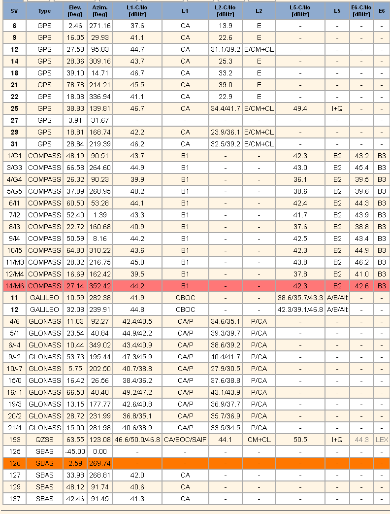
Multi-GNSS SVs and Signals in View
To highlight this point, just glance at the following graphical log file generated by software in the latest Trimble Multi-GNSS PNT receiver. The chart depicts a log file from a receiver located in Singapore. The location is significant only because in that location the receiver is in full view of the Japanese QZSS-1 PNT SV and all its extra U.S. originated PNT signals (L2C & L5) mentioned earlier. This particular Trimble receiver is networked and reports results automatically and continuously to a web page, while receiving GVRS updates and corrections plus other PNT information, such as an updated almanac, over the same network. The question becomes, is it a PNT device with a computer and embedded communications? Or is it a computer with communications and an embedded PNT function? You be the judge. Regardless of which you choose, this is the future of PNT and MUE.
This civil receiver reports 40+ SVs with 169 separate signals in view and usable. This does not count the number of Wi-Fi and/or GVRS signals it is capable of receiving. Meanwhile, a GPS MUE receiver in the same location only observes a total of 10 SVs it can process for a total signal count of 20. However, one of the key points on this log depiction has to do with integrity. Notice the orange and red lines. They indicate that the receiver has labeled these signals as “suspect” and has automatically dropped them from the solution for any of a host of reasons — a failed integrity check, jamming, spoofing, wrong way path, a runaway clock, etc. You name it, and if it is suspicious, the receiver will drop that SV and its signals from its PNT calculations. Built-in integrity.
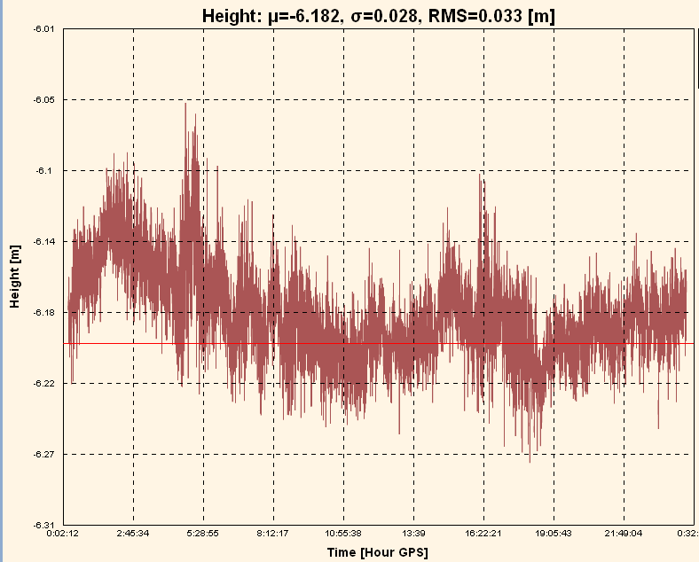
The obvious question becomes just how accurate is this Trimble receiver over a 24-hour period? The next graphical log file denotes that it is accurate within 3 centimeters.
Trimble multi-GNSS receiver web page log file denotes continuous availability of PNT signals with an average accuracy of 3 cms.
Assured PNT
When we asked warfighters what was more important to them in a combat zone — availability or accuracy of the PNT signals, the answer was, not surprisingly, both. But, of course, they need to receive the signal first, and then they can worry about accuracy.
So, if you were Ms. Teri Takai and you were worried about “assured PNT,” would you rather do that with 20 signals from 10 SVs or 169 signals from 49 SVs and some very strong, difficult to jam, terrestrial signals as well — adding up to, on average, 33 times more accuracy than the GPS-only signal? To me, the answer is obvious. And of course, all that is on the line with every mission the DoD performs, as is the safety of our critical national infrastructure as this next chart depicts.
Assured PNT or lack thereof impacts all missions, across all platforms and domains
Assured GPS MUE PNT today depends on:
L1(C/A), L2 P(Y), SAASM (Future M-Code)
Accuracy ~ 1m
Assured Multi-GNSS MUE PNT with all signals available depends on:
GPS L1/L2/L5/L1C/L2C/M-Code/SAASM
SBAS (WAAS, EGNOS, MSAS, GAGAN, SDCM+)
GLONASS L1/L2/L5
Galileo E1/E5 (CBOC & Alt BOC)
Compass B1/B2/B3
QZSS GEO – L1 CA/C/SAIF, L2C, L5, LEX Pilot
Two-way communications, Networking, PNT servers, each PNT device with unique IP address and each PNT device serves as a sensor
Software definable devices
Multiple software applications (Apps)
Accuracy ~ 3 cm
Army Making Strides
I spoke above about DARPA getting into the PNT business, and that is a good thing. But how about the largest military user of PNT, the United States Army? The U.S. Army is making some interesting changes as well. The Army announced a few months ago that there would be no more purchases of DAGRs, and that it was pursuing smartphones as a communications and small computing platform as well as an alternate PNT tool and display device. This is where the Puck comes into play.
While it is a wonderful idea I fully endorse, the problem with the Puck is that under the current design scheme it will still only transmit the current two GPS signals to a smartphone or other PNT display device. And warfighters lament that it is another device run by batteries for which our warfighters need to carry spares. Why not make the Puck a multi-GNSS device? we asked. The answer we received is that it would make it too power hungry and just require more batteries. So to misquote Shakespeare “…for want of a battery, the war was lost?” The Army is definitely on the right track, but they need to figure out how to make the Puck a multi-GNSS device. Can you say Lithium ION and solar charger – Hoorah!?
The Army Hub
The Puck is moving in the right direction. However, with the addition of another device, the Army is definitely on the right track. This device is designated the “Hub,” and while it is again GPS-oriented, it contains multiple terrestrial and internal signal augmentations and backups, as the image depicts.
With apologies to the U.S. Army, I unabashedly modified the chart, and I made it very obvious. The red text depicts my addition of a multi-GNSS card or module versus or in addition to the CGM (Common GPS Module) and GB-GRAM or Ground-Based GPS Receiver Application Module. The multi-GNSS card/module already exists today. Several PNT receiver manufacturers manufacture it with 28-nm technology versus the 95-nm technology — for the as-yet-unavailable for about four more years if the rumors are correct — GPS-only CGM. For me, the addition seems to be an easy fix, as there is lots of room in the Hub. But this fix or module (CGM) is years and millions of dollars down the road, versus a solution that exist today.
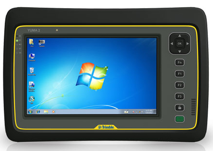
YUMA 2 or Hub or Both
The solution, frankly, is one of the smart tablets available today from numerous manufacturers — seven, actually, that have the wherewithal to produce a secure multi-GNSS device with a SAASM module.
The Trimble Yuma 2.
This is an example of the solution in the form of a Yuma 2 tablet computer from Trimble, which I am in the processing of reviewing for GPS World. The Yuma 2 has all the multi-GNSS features we have been discussing and more, plus it can in time accommodate all the modules scheduled to be incorporated into the Hub. Why build a whole new display device when the core already exists with many more capabilities than were imagined or real estate would ever allow for the Hub? Plus, it is available today as a rugged Mil-Spec device with a full color, high-resolution touch screen. And in the end it will provide a 3-cm solution versus a 1-meter solution. What more could you want? And it is available today with an outstanding and intuitive interface.
Conclusion – Services PNT UE Trends
I have been focusing on the Army today not simply because they are the biggest U.S. military user of PNT devices, but because they are moving in the right direction for the future of PNT and MUE devices. Of course, all the services and many agencies need a well-thought-out and secure PNT solution, and if we have learned anything it is that one size does not fit all. Indeed, our national security and our national infrastructure depend upon future PNT devices. For security purposes alone, they should have a certain degree of application and signal diversity.
Now let’s review:
Army has a way ahead with an assured PNT program.
Includes end of PLGR and DAGR and adding new networkable devices.
Plans for fourth-generation multi-GNSS and multi-function handheld devices and embedded PNT devices as sensors to include the Puck and Hub.
Marine Corps: Decertified PLGRs in 2009 and attempts to limit the use of DAGRs.
DAGRs used primarily as embedded devices.
Purchasing approved SAASM devices from commercial vendors.
USAF: Outfitted 70% of aircraft with modern, integrated, networkable and upgradeable PNT devices.
Navy: More than 60% of the fleet outfitted with modern PNT networked devices.
The Bottom Line is – One size does not fit all but one conclusion is clear – while GPS may and will always hopefully be the Gold Standard – multi-GNSS solutions are the future.
The Future of PNT Devices
This last list depicts the future of PNT as best as I can define it; indeed, as it has already been defined for us by our warfighters and first responders or, as Kirk Lewis would have me say, government users. The users are not waiting around, nor have they bothered to adhere to woefully out-of-date regulations. It is what they desire, and since their lives depend on it, it is what they should have.
Multi-GNSS — Utilize all PNT signals available.
Space and Terrestrial (GPS, GLONASS, eLORAN).
Traditional and non-traditional (Wi-Fi, GVRS, carrier signals).
Multi-function COTS devices with non-proprietary OS (operating System), intuitive interfaces and Mil-Spec ruggedized.
Multiple methods of communications: Wi-Fi, Skype, 4G, text, auto-text, satellite.
Software Downloads – Applications
COTS applications plus .mil apps store.
Networked devices for SA, updates and PNT,
Real-time satellite imagery and mission data injects.
Defense and intelligence LBS.
Each device will be a sensor on a network,
Automatically report jamming, interference and location data.
Utilize SAASM and anti-jam military signals only as required.
Thanks you for your time and kind attention today. And remember, Happy Navigating!
Alan Cameron, publisher and editor, and Don Jewell, contributing editor for defense, will be blogging live from the 2012 JSDE/ION Joint Navigation Conference. The conference will be held June 12-15 in Colorado Springs, Colorado. Cameron and Jewell will be blogging twice a day with all the news from the defense-oriented conference.
Among many other matters, we’ll be taking a close-up look at NovAtel’s and L-3’s new SAASM receiver. This is a classified piee of hardware, of course, but we should be able to glean some details on this and other new defense products and services being rolled out at the exhibit accompanying the conference.
In addition, we’ll have a top-level view of the Warfighters’ Panel on June 15. A similar session was the undisputed highlight of the GPS Partnership Council in late April, and we expect more of the same here. GPS World columnist Don Jewell is organizing this panel.
According to organizers, JNC 2012 will be the largest U.S. military navigation conference of the year with joint service and government participation. The event will focus on technical advances in positioning, navigation and timing (PNT) with emphasis on joint development, test and support of affordable PNT systems, logistics, and integration. From an operational perspective, the conference will also focus on advances in battlefield applications of GPS, critical strengths or weaknesses of fielded navigation devices, warfighter PNT requirements and solutions, and navigation warfare.
Watch the home page Top Story for the blogs, beginning Tuesday, June 12.
Several new rugged GPS-enabled devices were announced this week.
Juniper Systems has partnered with Pennsylvania-based SDG Systems to market the Mesa Rugged Notepad with Android (AOSP) 2.3 operating system, a rugged handheld computer known as the RAMPAGE 6 and distributed through SDG Systems. Availability of the RAMPAGE 6 is scheduled for the third quarter of 2012 and its first public presentation will be at the Esri International User Conference in San Diego, July 23–27, 2012.
The Android (AOSP) 2.3 operating system on the RAMPAGE 6 offers many advantages for data collection, including easy multi-tasking, a modern user interface, rich programming environment, multi-platform development, abundant application data storage, open source flexibility, and the opportunity for a custom Android interface developed by SDG Systems, according to Juniper Systems. Additionally, its optional kiosk mode allows only certain applications to be accessible by the user, creating a single-purpose device without distractions, Juniper Systems said.
The RAMPAGE 6 will have the same features as the Mesa Rugged Notepad, including a large 5.7-inch viewing display, IP67 ingress protection rating for water and dust, integrated 2–5 meter GPS receiver, optional integration of a 1D/2D barcode scanner, and optional Class I, Division 2 certification for use in hazardous locations.
Meanwhile, DRS Technologies, Inc., announced today that its Tactical Systems division has expanded its product portfolio with three new ARMOR rugged tablets. The ARMOR X7et and the ARMOR X7ad are thin, lightweight tablets based on customers requesting even more portable computers from ARMOR, the company said. “The 7-inch multi-touch tablets shatter the perception of bulky, rugged computing, and offer field service workforces the ability to choose between the fast-growing Android OS and the enterprise-friendly Microsoft Windows platform,” The company said. Additionally, DRS is now offering a new light convertible tablet, the ARMOR X12kb, that meets MIL-STD-810G. All three follow introduction of the ARMOR X7 compact rugged tablet launched in 2011.
The ARMOR X7et is a Windows-based tablet that weighs less than 1.5 pounds and provides six hours of battery life. It features an Intel Atom Z670 processor and runs Microsoft Windows 7 Professional. Its Android counterpart, the ARMOR X7ad, weighs 1.3 pounds and operates for up to eight hours. It features a NVIDIA Tegra 2, 1.0-Ghz dual-core processor, and operates on Android v3.2. Both lightweight tablets feature a 7-inch outdoor-readable multi-touch screen display. They are certified to MIL-STD 810G for extremes in temperature, vibration, shock, and four-foot drops and have an IP65 rating for ingress protection, which means they are fully protected against dust and can withstand low pressure jets of water from all directions.
Weighing 5.5 pounds, the ARMOR X12kb features a 12.1-inch sunlight-readable swivel touchscreen that incorporates polarized LCD glass and anti-reflective technology. The ARMOR X12kb offers the Intel Core i5-560UMCPU processor and runs Microsoft Windows 7 Professional. It has a long battery life, operating for up to eight hours, as well as a spill-proof keyboard and touchpad. Additionally, the one-click stealth mode operation disables all emitting light and sounds, a feature designed for the unique applications of covert operations.
The three new ARMOR mobile computers include connectivity options including Gobi Wireless Broadband, integrated GPS, 802.11 b/g/n Wi-Fi, and Bluetooth wireless. They are designed to make it easier for workers to use mobile computing in rugged environments, as this product video shows:
A portable spoofer implemented on a digital signal processor mounts a spoofing attack, characterizes spoofing effects, and suggests possible defense tactics. GNSS users and receiver manufacturers should explore and implement authentication methods against sophisticated spoofing attacks.
By Todd E. Humphreys, University of Texas, Brent A. Ledvina, Virginia Tech, Mark L. Psiaki, Brady W. O’Hanlon, and Paul M. Kitner, Jr., Cornell University
Seven years after the Volpe Report warned that “[a]s GPS further penetrates into the civil infrastructure, it becomes a tempting target that could be exploited by individuals, groups, or countries hostile to the U.S.,” civil GPS receivers remain as vulnerable as ever to this threat. Among other types of interference, the Volpe report considers civil GPS spoofing, a pernicious type of intentional interference whereby a GPS receiver is fooled into tracking counterfeit GPS signals. More sinister than intentional jamming, spoofing deceives the targeted receiver, which cannot detect a spoofing attack and so cannot warn users that its navigation solution is untrustworthy. The Volpe report noted the absence of any off-the-shelf defense against civilian spoofing and lamented that “[t]here also is no open information on . . . the expected capabilities of spoofing systems made from commercial components.” It recommended studies to characterize the spoofing threat: “Information on the capabilities, limitations, and operational procedures [of spoofers] would help identify vulnerable areas and detection strategies.”
We recently canvassed four manufacturers of high-quality GPS receivers. They revealed that they were aware of the spoofing vulnerability but had not taken steps to equip their receivers with even rudimentary spoofing countermeasures. The manufacturers expressed skepticism about the seriousness of the threat and noted that countermeasures, if required, had better not be too expensive. Such attitudes propel further examination of the threat and practical countermeasures.
Important research into spoofing countermeasures during the last decade begins with an internal memorandum from the MITRE Corporation recommending these techniques to counter spoofing:
Amplitude discrimination
Time-of-arrival discrimination
Consistency of navigation inertial measurement unit (IMU) cross-check
Polarization discrimination
Angle-of-arrival discrimination
Cryptographic authentication
The first two techniques could be implemented in software on GPS receivers, but would be effective against only the most simplistic attacks. The next three tactics would be effective against some — but not all — more sophisticated attacks. In particular, angle-of-arrival discrimination, which exploits differential carrier-phase measurements taken between multiple antennas, could only be spoofed by a sophisticated coordinated spoofing attack (discussed later). However, they require additional hardware: multiple antennas or a high-grade IMU, whose cost militates against widespread adoption.
Cryptographic authentication, the last technique on the list, has received detailed study since 2001. Logan Scott offered several levels of authentication in a 2003 ION GPS/GNSS paper and urged their prompt adoption in a GPS World op-ed column in July 2007. His methods are backward-compatible with non-compliant GPS receivers. Spreading-code authentication, the basis for his Level 2 and 3 authentication, entails embedding messages in the GPS ranging codes and periodically authenticating these messages. Because this method effectively binds a digital signature to the ranging codes, it would render a compliant receiver practically impervious to a spoofing attack except during the short interval between reception and authentication of the embedded messages.
These cryptographic techniques all require modification of the civil GPS signal structure. Such changes appear extremely unlikely in the short term because, as one experienced observer noted, “signal definition inertia is enormous.” A less effective but more practical approach over the United States would be to authenticate only the WAAS signal managed by the U.S. Department of Transportation and the Federal Aviation Administration. Since the WAAS signal is constructed on the ground and transmitted via bent-pipe communication spacecraft, it is more amenable to immediate modification. Even so, efforts to persuade WAAS officials to adopt spreading code authentication have so far proven fruitless.
The Homeland Security Institute, a research arm of the U.S. Department of Homeland Security, has also considered the threat of civil GPS spoofing. On its website it has posted a report listing seven spoofing countermeasures. The proposed countermeasures include the first three techniques from the list here. Some of the remaining four countermeasures would be trivial to spoof. None of the seven would adequately defend against a sophisticated attack. Nonetheless, the posting claims that its proposed techniques “should allow suspicious GPS signal activity to be detected.” We worry that such optimistic language in such a prominent posting will mislead many readers into believing that the spoofing threat has been adequately addressed.
Our goals here are to assess the spoofing threat and develop and test practical and effective countermeasures. To advance these goals we found it necessary to go through the exercise of building a civil GPS spoofer. The process of developing a complete portable spoofer allows one to explore the range of practical spoofing techniques. Thus one discovers which aspects of spoofing are hard and which are easy to implement in practice. With this information, we can more accurately assess the difficulty of mounting an attack, and receiver developers can prioritize their defenses by choosing countermeasures that are effective against easily implementable spoofing techniques.
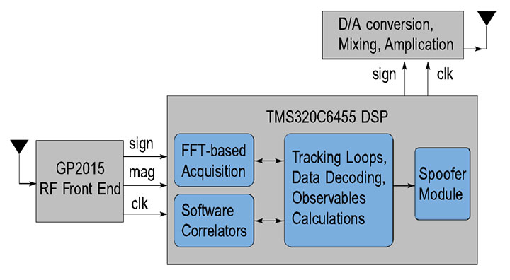
Software-defined GPS receivers furnish a natural platform for the study of civil spoofing and its effects. In a software receiver, real-time correlators, tracking loops, and navigation solver are all implemented in software on a programmable processor.
Initial Threat Assesment
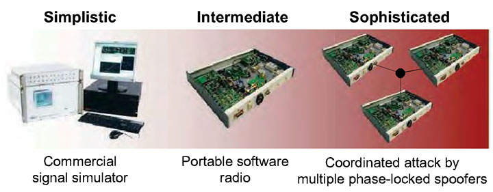
Consider the spoofing threat continuum in FIGURE 1, roughly divided into simplistic, intermediate, and sophisticated spoofing attacks for threat analysis.
FIGURE 1. The spoofing threat continuum: simplistic, intermediate, and sophisticated spoofing attacks.
Simplistic Attack via Simulator. As far as we know, all stand-alone commercial civilian GPS receivers available today are trivial to spoof. One simply attaches a power amplifier and an antenna to a GPS signal simulator and radiates the RF signal toward the target receiver. A successful attack along these lines was demonstrated by researchers at Argonne National Laboratories in 2002.
Despite the ease of such an attack, it has some drawbacks. One is cost: the price of modern simulators can reach $400,000. Simulators can be rented for less than $1,000 per week, making them accessible for short-term mischief, but long-term use remains costly. Size is another drawback. Most GPS signal simulators are heavy and cumbersome. If used in the simplest attack mode, situated close to a target receiver’s antenna, a signal simulator would be challenging to plant and visually conspicuous. Of course, if the custodian of the target receiver is complicit in the spoofing attack — as is the case, for example, with the fishing vessel skipper who spoofs the onboard monitoring unit to fish undetected in forbidden waters — the conspicuousness of the signal spoofer is irrelevant.
The menace posed by such an attack is diminished by the fact that it is likely easy to detect, because of the difficulty of synchronizing a simulator’s output with the GPS signals in its vicinity. An unsynchronized attack effectively acts like signal jamming, and may cause the victim receiver to lose lock and have to undergo a partial or complete reacquisition. Such a forced re-acquisition would raise suspicion of a spoofing attack. If the unsynchronized attack somehow avoids causing loss-of-lock, it will nonetheless cause an abrupt change in the victim receiver’s GPS time estimate. The victim receiver could flag jumps of more than 100 nanoseconds as evidence of possible spoofing. The spoofer can attempt to counter this defense by intentionally jamming first and then spoofing, but an extended jamming is itself telltale evidence of interference.
Of course, the fact that a simulator-type attack is easy to defend does not increase security. A gaping vulnerability will remain until civil GPS receivers at least are equipped with the rudimentary spoofing countermeasures required to detect a simulator-type attack.
Intermediate Attack. One of the challenges that must be overcome to carry out a successful spoofing attack is to gain accurate knowledge of the target receiver antenna’s position and velocity. This knowledge is required to precisely position the counterfeit signals relative to the genuine signals at the target antenna. Without such precise positioning, a spoofing attack is easily detected.
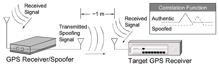
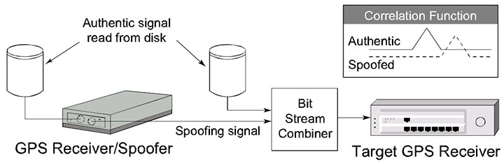
An attack via portable receiver-spoofer, portrayed in FIGURE 2, overcomes this difficulty by construction. The receiver-spoofer can be made small enough for inconspicuous placement near the target receiver’s antenna. The receiver component draws in genuine GPS signals to estimate its own position, velocity, and time. Due to proximity, these apply approximately to the target antenna. Based on these estimates, the receiver-spoofer then generates counterfeit signals and generally orchestrates the spoofing attack. The portable receiver-spoofer could even be placed somewhat distant from the target receiver if the target were static and its position relative to the receiver-spoofer had been pre-surveyed.
FIGURE 2. Illustration of a spoofing attack via portable receiver-spoofer.
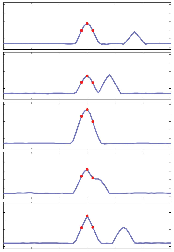
Each channel of the target receiver is brought under control of the receiver-spoofer as illustrated in the inset at the upper right of Figure 2. The counterfeit correlation peak is aligned with the peak corresponding to the genuine signal. The power of the counterfeit signal is then gradually increased. Eventually, the counterfeit signal gains control of the delay-lock loop tracking points that flank the correlation peak.
As one might imagine, there are no commercially available portable receiver-spoofer devices. This of course decreases the present likelihood of the receiver-spoofer attack mode. Nonetheless, the emergence of software-defined GPS receivers significantly erodes this barrier. As we demonstrate here, the hardware for a receiver-spoofer can be assembled from inexpensive off-the-shelf components. The software remains fairly sophisticated, but it would be unwise to assume it was beyond the capabilities of clever malefactors. The civil GPS signal structure is, after all, completely detailed in a publicly available interface control document, and entire books have been written on software-defined GPS receivers. In perhaps the most worrisome scenario, anticipated in Scott’s 2003 paper, the software definition of a receiver-spoofer may someday be available for download from the Internet. The expertise required to download and exercise the code would surely be within the reach of many potential malefactors.
An attack via portable receiver-spoofer could be difficult to detect. The receiver-spoofer can synchronize its signals to GPS time and, by virtue of its proximity to the target antenna, align the counterfeit and genuine signals. A receiver equipped with a stable reference oscillator and a low-drift inertial measurement unit (IMU, for receivers on dynamic platforms) could withstand an attack via receiver-spoofer for several hours. Eventually, however, a patient receiver-spoofer would gain undetected control by keeping its perturbations to time and position within the envelope allowed by the drift rates of the target receiver’s oscillator and IMU.
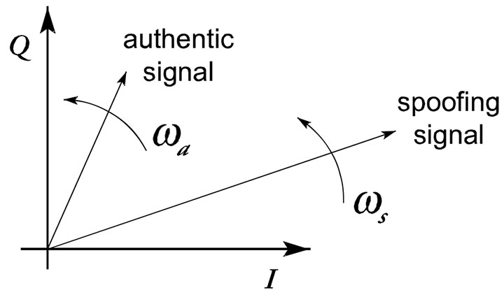
The only known user-equipment-based countermeasure that would be completely effective against an attack launched from a portable receiver-spoofer with a single transmitting antenna is angle-of-arrival discrimination. With a single transmitting antenna, it would be impossible to continuously replicate the relative carrier phase between two or more antennas of an appropriately equipped target receiver.
While an intermediate attack is not presently likely because the requisite device is not readily available, the emergence of software-defined GPS receivers increases its future likelihood. Furthermore, this mode of attack could defeat most known user-equipment-based spoofing countermeasures.
Sophisticated Attack. The angle-of-arrival defense against a portable receiver-spoofer can be thwarted by a coordinated attack with as many receiver-spoofers as antennas on the target receiver. Imagine a receiver-spoofer the size of a pack of cards, small enough to mount directly atop a target antenna. The receiver-spoofer’s receiving and transmitting antennas are situated respectively on the upper and lower faces of the device and are shielded to avoid self-spoofing. Now imagine several such devices sharing a common reference oscillator and communication link, with each device mounted to one of the target receiver’s antennas. The angle-of-arrival defense fails under this attack scenario.
Naturally, this attack inherits all of the challenges of mounting a single receiver-spoofer attack, with the additional expense of multiple receiver-spoofers and the additional complexity that the perturbations to the incoming signals must be phase-coordinated.
The only known defense against such an attack is cryptographic authentication.
Thus, an attack via multiple phase-locked portable receiver-spoofers is somewhat less likely than an attack via single portable receiver-spoofer, but may be impossible to detect with user-equipment-based spoofing defenses.
Target Spoofer Type. The foregoing discussion of the spoofing threat continuum suggests that a spoofing attack via GPS signal simulator poses the greatest near-term threat. However, there are known effective defenses against such an attack, and these can be implemented in software on commercial GPS receivers. In contrast, an attack launched from one or more portable receiver-spoofer(s) poses the greatest long-term threat. Known user-equipment-based defenses against such attacks are few and of limited effectiveness. Accordingly, we focus here on the portable receiver-spoofer attack mode. To better understand this mode, we built a software-defined portable receiver-spoofer as a research platform.
Architecture
We developed a software-defined receiver-spoofer as an extension of the Cornell GRID receiver, adding a spoofer software module and transmission hardware; see FIGURE 3.
FIGURE 3. Block diagram of the reciever-spoofer architecture.
Receiver Module. The hardware consists of an RF front end, a complex programable logic device (CPLD) for signal multiplexing (not shown), and a digital signal processor (DSP). The receiver software includes a full navigation solution engine. Software is entirely written in natural-language C++ to facilitate code development and maintenance.
The software correlation engine, based on a bit-wise parallel correlation technique, is crucial to meeting real-time deadlines in the receiver-spoofer under the simultaneous burdens of receiver processing and spoofing. Here is an overview.
FIGURE 4 depicts the standard correlation operation that occurs within any GPS receiver. The incoming signal x(t) is mixed by complex multiplication with a complex local signal replica, xl(t). The product is integrated over a short interval (typically 1–20 milliseconds) and sampled to produce the quadrature baseband components Ik and Qk , also known as baseband accumulations.
FIGURE 4. Standard correlation operation. The local signal replica xl(t) is complex and ⊗* denotes complex multiplication.
FIGURE 5 depicts a byte-wise software implementation of the standard correlation operation. In this implementation, the individual signal samples are stored in 8-bit bytes.
FIGURE 5. Byte-wise implementation of the correlation operation. Boxes in the signal trains represent bytes, each of which stores an 8-bit signed representation of the signal x or of the complex local replica xl. Grayed boxes represent the operands of one complex multiplication operation.
Because many DSPs and general-purpose CPUs are capable of performing several multiply-and-accumulate operations in parallel (for example, eight in high-performance fixed-point DSPs), the byte-wise implementation can be quite computationally efficient. However, storing the local carrier and code replica samples as bytes makes the tables in which they are packed for efficient table look-up prohibitively large for storage in on-chip (fast) memory. Furthermore, despite its computational efficiency, the byte-wise implementation is still only one-quarter to one-half as fast as the bit-wise parallel implementation when implemented on a high-performance fixed-point DSP.
FIGURE 6 depicts the bit-wise parallel correlation implementation. The operation assumes the incoming signal and the local signal replicas are quantized to two bits — one sign and one magnitude bit. The sign and magnitude bits are packed into 32-bit words. Explicit complex multiplication is replaced by a combination of the bit-wise logical operations AND, NOR, and XOR. In effect, the bitwise parallel method performs 32 multiply-and-accumulate operations in parallel. Importantly, storage of the local carrier replicas as bit-packed sign and magnitude words is also memory-efficient, which makes on-chip storage of the local signal replica look-up tables possible.
FIGURE 6. Bit-wise parallel implementation of the correlation operation. Boxes in the signal trains represent 8-bit bytes. Grayed boxes represent operands of one complex multiplication operation, implemented by bit-wise AND, NOR, and XOR operations. (Click to enlarge).
Spoofer Module. Beyond the hardware required for the GPS receiver, the receiver-spoofer requires only signal transmission hardware: a digital/analog converter, a frequency synthesizer and mixer for mixing to near the GPS L1 frequency, in-line attenuators, and a transmission antenna. For this article, we conducted no over-the-air tests to avoid possible FCC violations; hence, we do not further discuss the transmission hardware.
The heart of the spoofer is the spoofer software module, shown in FIGURE 7.
FIGURE 7. Block diagram of the spoofer module.
Control Module: The spoofer’s control module coordinates a spoofing attack by directing the frequency, code-phase offset, and signal amplitude applied in each of n spoofing channels. Some components of the control module described here remain under development.
The control module accepts the following inputs from the receiver module:
estimates {t (circumflex) k } 1 n of the start times of the kth C/A code period on receiver channels 1–n;
the estimates {θ (circumflex) k } 1 n of the beat carrier phase on receiver channels 1–n at times {t (circumflex) k } 1 n ;
the estimates {f (circumflex) D,k } 1 n of the Doppler frequency shift on receiver channels 1–n at times {t (circumflex) k } 1 n ;
the estimates {A (circumflex) k } 1 n of the signal amplitudes on receiver channels 1–n at times {t (circumflex) k } 1 n ;
the receiver-spoofer’s current 3-dimensional position P and velocity V.
The control module orchestrates a spoofing attack in the following way. It begins by commanding n spoofer channels to generate signals with Doppler frequency offsets equal to {f (circumflex)D,k } 1n and code phases whose relative alignment is equivalent to that dictated by {t (circumflex)k } 1n. It then applies a common-mode code phase advance to compensate for buffering delays within the receiver-spoofer. If this advance is chosen correctly, then each spoofing signal will be code-phase-aligned with its genuine-signal counterpart at the target receiver’s antenna. The control module then commands an increase in the signal amplitude of one or more spoofer channels to effect lift-off of the target receiver’s tracking points. This continues until all target receiver channels are presumed to be under control of the spoofer.
At this point the control module gradually leads the target receiver off its true position and time to an alternate position or time. Let ΔxD (tk ) = [Δvx (tk ), Δvy (tk ), Δvz (tk ), Δb•(tk )]T be the perturbation that the control module applies to the target receiver’s observed velocity and clock rate bias at receiver-spoofer time tk . The time rate of change of the perturbation Δb•(tk ) must be less than the expected drift rate of the target receiver’s reference oscillator. Likewise, the time rate of change of the velocity perturbations Δvx (tk ), Δvy (tk ), and Δvz (tk ) must be less than the accelerations that the target receiver expects, or, if the target receiver is equipped with an IMU, less than the expected uncertainty in the accelerometer bias.
To enforce ΔxD (tk ), the control module linearizes the standard Doppler frequency measurement model about the current receiver time, position, and velocity estimates and computes offsets to the quantities {f (circumflex)D,k } 1n that are commensurate with the perturbation ΔxD (tk ).
Similarly, let Δx(tk ) = [Δx(tk ), Δy(tk ), Δz(tk ), Δt(tk )]T be the perturbation that the control module applies to the target receiver’s observed position and time at receiverspoofer time tk . Δx(tk ) is calculated by integrating the time history of ΔxD (tk ) values from some initial condition, typically ΔxD (tk ) = 0 so that the target receiver’s observed velocity and clock rate bias is initially approximately equal to its true velocity and clock rate bias. To enforce Δx(tk ), the control module linearizes the standard pseudorange measurement model about the current receiver time and position estimates and computes offsets to the quantities {t (circumflex)k } 1n that are commensurate with the perturbation Δx(tk ).
Following this strategy, the control module can, as gradually as necessary, misdirect the target receiver’s observed position and time.
The spoofer control module currently makes no attempt to align the beat carrier phases of its output signals with those of the received GPS signals, and so the phase values {θ (circumflex)k } 1n are currently discarded. More sophisticated future versions of the receiver-spoofer will likely make use of these phase values.
Spoofer Channels: Each of the n spoofer channels is configured to correspond to one of the n authentic GPS signals that the receiver module tracks. The signal generated by the nth spoofer channel can be modeled as
(1)
(2)
where xn(τi) is the ith sample of the signal, τi is the time of the ith sample, An (τi ) is the control-module-commanded amplitude at τi , dn (τi ) is the data bit value that applies at τi , Cn (τi –tn,k ) is the C/A code chip value that applies at τi , tn,k is the control-module-commanded start time of the kth C/A code period, Q{•} is a 2-bit quantization function, fIF is the intermediate frequency, θn (τi ) is the beat carrier phase at τi , and fD,n,k is the control-module-commanded Doppler frequency shift at time tn,k . The C/A code function Cn(τ) can be further represented as
(3)
and the data bit function dn(τ) as
(4)
where {cn,1 , cn,2 , …, cn,1023 } and {dn,j , dn,j+1 , …} are the unique C/A code chip sequence and navigation data bit sequence corresponding to the GPS satellite whose signal is being emulated on the nth spoofer channel, Tc and Td are the duration of one C/A code chip and one navigation data bit, and ∏T(τ) is the usual rectangular support function equal to unity over 0 ≤ τ< T and zero otherwise.
To generate the C/A code samples {Cn (τi )}, i = 1,2, …, the spoofer channels make use of the same bit-packed C/A code replicas that are employed for signal correlation in the receiver module, which are stored in large look-up tables. However, to generate the samples of the quantized carrier replica
(5)
the spoofer channels cannot exploit the same bit-packed carrier replicas that are used for signal correlation in the receiver. This is because, to minimize on-chip memory requirements, the receiver’s carrier replicas all begin at the same phase value and have only a coarse 175-Hz frequency resolution. The receiver compensates for these factors by performing a rotational “fix-up” on the in-phase and quadrature accumulation values. Unfortunately, such a scheme is unworkable for generating the sampled carrier replicas in the spoofer channels because anything less than precise phase and frequency control over the carrier replicas would potentially alert a target receiver to a spoofing attack. Consequently, it was necessary to develop a carrier-replica generator more capable than that used in the receiver module.
Carrier-Replica Generator: Two requirements drove the carrier-replica generator design: precision and efficiency. Regarding precision, to evade detection the generator must be able to set the initial phase of a carrier replica segment to within approximately one degree and the Doppler frequency offset over the segment to within approximately 1 Hz. Regarding efficiency, to meet real-time deadlines the generator would have to be capable of generating a replica segment T S seconds long in less than T S /30 seconds. We developed a generator meeting these requirements.
A quantized sampled carrier replica can be represented in bit-wise parallel format as a block of 32-bit words. In the simplest case, the carrier replicas are one-bit quantized with 0 and 1 respectively representing the values –1 and 1. The carrier replica generator can be configured to generate 1- to 4-bit-quantized samples. Two-bit quantization was chosen for implementation within the spoofer, with one bit representing the sign and the other representing the magnitude of the signal. The choice of 2-bit quantization balanced a tradeoff between efficiency and the amount of quantization noise introduced into the final linear combination of the spoofer channel outputs.
The carrier replicas are sampled at a rate fS > 2fIF Hz as shown for the minimum and maximum Doppler frequency shifts in FIGURE 8. The key observation that makes real-time generation of the carrier replicas possible is the following: There is little diversity in the 32-bit words that result from packing 32 samples of quantized carrier replicas over a ±10-kHz range of Doppler frequency offsets and 2π radians of carrier phase. This is another way of saying that the information content of the quantized sampled carrier replicas is low, which is to be expected.
FIGURE 8. Two-bit quantization of the local carrier replica at the maximum and minimum Doppler frequency shifts.
Figure 8 illustrates this concept by showing a case with a sampling frequency fS = 5.714 MHz, an intermediate frequency fIF = 1.405 MHz, and a Doppler frequency range of ±10kHz. This Doppler frequency range covers the expected range of Doppler shifts seen by a terrestrial GPS receiver, with ~ 5 kHz of margin for receiver clock rate error. The sampling and intermediate frequencies are typical for civil GPS applications. Over the interval shown in Figure 8, the total number of cycles for the two signals, whose initial phases are aligned, differs by less than 1/8 of a cycle. When sampled and 2-bit quantized into the sign (s) and magnitude (m) bits that run along the bottom of each frame, the resultant carrier replicas have the same sign-bit history and only 10 different magnitude bits. This indicates that the sampled carrier replicas covering a reasonable Doppler shift frequency range are primarily a function of the initial phase offset for each 32-bit word. This observation remains true whenever fIF < fS and fD,mabs << fIF , where fD,mabs is the maximum absolute value of the Doppler frequency shift.
The low information content of the sampled carrier replicas makes them amenable to tabular storage and efficient retrieval. Two tables are required, one each for the sign and magnitude bits. Let if ∈ {0,1, …, Nf – 1} and iθ ∈ {0,1, …, Nθ – 1} represent the respective indices into the frequency and phase dimensions of the tables. For each carrier replica segment (typically 1-ms long), a single frequency index is calculated as
(6)
where fD is the exact desired frequency and fD,min and fD,max are the minimum and maximum Doppler frequency shifts. The phase index iθ is different for each of the 32-bit words that are strung together to compose the carrier replica segment. Let τk be the time offset of the midpoint of the kth word in the segment relative to the time of the first sample in the segment. The phase at the midpoint of the kth word is calculated as
(7)
where θ0 is the phase of the first sample in the segment, and the modulo operation is modulo 2π. Finally, the phase index of the kth word is calculated as
(8)
To meet precision requirements, the number of indices into the frequency and phase dimensions of the tables were set respectively to Nf = 32 and Nθ = 256. With this table size, the table-generated carrier replicas are not significantly different from carrier replicas generated by applying the exact phase and frequency values using double-precision computations. The sign and magnitude tables occupy a total of 64 kB in on-chip memory.
Data Bit Predictor: The GPS L1 navigation data bit sequence {d n,j , d n,j+1 , …} required by the nth spoofer channel is most easily generated in one of two ways. The simplest approach is to pass data bits to the spoofer channels as soon as they can be reliably read off the incoming GPS signals. Naturally, this approach produces a delay in the arrival time of the spoofing data bit as compared to that of the true data bit at the target receiver’s antenna. The delay is most conveniently made an integer number of 1-ms C/A code intervals. Clearly, such a delay is undesirable in a spoofer because a target receiver could be designed to watch for such a delay and thereby detect a spoofing attack.
The second approach is to predict the data bits based on knowledge of the bit structure and a recent bit observation interval. This is the function of the receiver-spoofer’s data bit predictor. This method relies on the fact that the GPS navigation message has a 12.5-minute period and remains nearly perfectly predictable for a period of two hours. In fact, the almanac component of the 12.5-minute data block is refreshed by the GPS Control Segment only once per day, and the remaining data — the individual satellite ephemeris data — can be observed in less than one minute. There are data bit segments within the TLM word of the navigation message that are unpredictable on a regular basis. However, these segments are also unpredictable for the target receiver (in the absence of external data bit aiding). Therefore, the spoofer can simply fill the unpredictable data bit segments with arbitrary data bits and adapt the parity bits and HOW word polarity accordingly.
Discrepancies have been observed between the almanac data of Block IIA and later satellites. For example, the least significant bits of particular ephemeris parameters can differ. This is believed to be a rounding error in early satellites. These discrepancies cause problems with data-bit prediction for Block IIA satellites. The GPS control segment has been alerted to this and is taking corrective measures. Meanwhile, the spoofer module’s data-bit predictor keeps two copies of almanac data: one for Block IIA and one for later satellites.
During a spoofing attack, rising GPS satellites pose a challenge for the data-bit predictor; indeed, for the entire receiver-spoofer. The receiver-spoofer must prevent the target receiver from acquiring bit lock on the new signal until the data-bit predictor has a chance to observe the new satellite’s ephemeris data. This could be done by transmitting a spoofing signal with arbitrary data bits whose boundaries change sporadically by an integer number of C/A code periods.
Sample-Wise Combiner: Summation of the bit-packed signals generated in each of the spoofer channels is performed sample by sample. The ith sample from the nth spoofer channel is weighted by A n (τ i ) and summed with the corresponding samples from the other spoofer channels, each weighted appropriately. While computationally expensive, sample-wise operations are necessary to generate a combined signal that represents a quantized superposition of the individual spoofing signals with correct relative amplitudes. The composite signal is then re-quantized to 1 or 2 bits before being loaded into the output circular buffer. Re-quantization of the composite signal introduces additional signal distortion, which decreases the carrier-to-noise ratio of each component signal. For 1-bit re-quantization, which is the current configuration, the signal distortion is tolerable until more than eight spoofing signals are combined. More precisely, 1-bit requantization can sustain no more than eight equal-amplitude component signals at a carrier-to-noise ratio of C/N 0 = 48 or higher.
Implementation
The software-defined receiver-spoofer has been implemented on the Cornell GRID receiver platform (FIGURE 9). Receiver and spoofer software modules run on the same processor.
FIGURE 9. The Cornell GRID receiver, hardware platform for the receiver-spoofer.
When tuned for efficiency, the receiver-spoofer meets real-time deadlines with computational resources to spare. At full capability, the receiver-spoofer tracks 12 GPS L1 C/A signals and simultaneously generates 12 spoofing signals, in addition to performing a 1-Hz navigation solution and continuous background acquisition. The 1-bit re-quantization of the composite spoofing signal limits the spoofer module practically to eight component signals. Future versions of the receiver-spoofer may trade computational resources for 2-bit re-quantization, permitting more than eight component spoofing signals.
The marginal computational demands of each tracking and spoofing channel are respectively 1.2 percent and 4 percent of the DSP, the latter value reflecting the high computational cost of carrier replica generation and sample-wise signal combination within the spoofer module.
The core Cornell GRID receiver software is the product of hundreds of developer-hours of work. Developing the spoofer module and extending the core GRID receiver software to include it required a team of three experienced developers working approximately 40 hours apiece, or approximately three developer-weeks. The hardware components of the receiver-spoofer platform shown in Figure 9 are all off-the-shelf components whose total cost is approximately $1,500.
Demonstration Attack
We devised a method for demonstrating a spoofing attack without actually transmitting RF signals at the GPS L1 frequency over the air, which would have violated FCC restrictions on transmitting in a protected band. An interval of digitized authentic GPS L1 C/A code data sampled at 5.7 MHz was stored to disk. The data were input to the receiver-spoofer, which tracked the six GPS signals present, generated corresponding spoofing signals, and combined these into a 1-bit quantized output bitstream. The output bitstream was then combined with the original data by interleaving, and the resulting bitstream was input to a Cornell GRID receiver acting as target receiver, as shown in FIGURE 10.
FIGURE 10. The “bit combination” framework for demonstrating a spoofing attack.
The receiver-spoofer accurately reproduced the code phase, frequency, data-bit values, and relative amplitude of all six GPS L1 signals present. The spoofing signals’ carrier phases, while not designed to match those of the genuine signals, were continuous across accumulation intervals as intended.
To enable observation of the spoofing attack, the target receiver was augmented with correlator taps at 81 different 0.2-chip offsets about the prompt tap, which is nominally aligned with the incoming signal. The amplitude time history from each correlator tap can be combined to produce “footage” of the spoofing attack from the perspective of the individual channels.
FIGURE 11 shows a sequence of frames depicting the attack on one of the channels. The attack lasts approximately 30 seconds. Each successive panel represents a snapshot of the 81 taps’ amplitudes at roughly 6-second intervals. The three red dots represent the delay-lock loop’s tracking points, which continuously attempt to align themselves so that the center point is maximized and the flanking points are equalized. The top frame shows the tracking points nicely aligned on the genuine signal’s correlation peak, while the counterfeit signal’s peak approaches furtively from the right. Of course, in a typical spoofing attack, the counterfeit peak would simply be initially aligned with the genuine peak and initially smaller than the counterfeit peak in the top panel; its approach from the right and large size in the present case is merely for clarity of presentation.
FIGURE 11. A sequence of frames (from top to bottom) showing a successful single-channel spoofing attack.
After the spoofed peak aligns with the genuine one, its signal power is gradually increased until it begins to control the tracking points. Eventually, the counterfeit peak drags the tracking points off to the left of the true peak. In the lower two panels of Figure 11, the true peak appears to drift off towards the right because the counterfeit peak has hijacked the 81 taps of the figure’s image zone, which are tied to the victim receiver’s tracking points, and it drags them all leftward relative to the true peak. A sophisticated spoofing attack will attempt right-to-left, or late-to-early, tracking lift-off wherever possible so as to disguise the attack as multipath.
FIGURE 12 illustrates the attack from the perspective of the baseband phasors in the complex plane. In the present version of the receiver-spoofer, no attempt is made to phase-align the authentic and spoofing signals. Consequently, a sign change in the data bit stream is possible as the spoofing phasor’s amplitude gradually increases and the target receiver’s phase-lock loop eventually transitions from tracking the authentic phasor to tracking the spoofing phasor. However, the rotational rates of the two phasors, ωa and ωs in Figure 12, should be nearly equivalent. From Figure 12 it should be apparent that if a receiver-spoofer were capable of phase-aligning with a genuine signal, it could, by transmitting the exact difference between a desired spoofing signal and the true signal at the target antenna, simultaneously produce a spoofing phasor and suppress the authentic phasor. When combined with data-bit prediction, such an attack could be impossible to detect relying solely on user-equipment-based defenses.
FIGURE 12. The authentic and spoofing baseband phasors with respective rotational rates of a and s on the complex I-Q plane.
Countermeasures
Three spoofing countermeasures have been suggested by work to date. Two of these, both software-defined user-equipment-based defenses, are presented here. These can be thought of as additions to the five user-equipment-based countermeasures presented earlier. The third method, a promising low-impact cryptographic technique, will be disclosed in a separate publication. Neither of the user-equipment-based defenses discussed below is spoofproof; however, each is straightforward to implement and increases the difficulty of mounting a successful spoofing attack.
Data-Bit Latency Defense. The data bit-latency defense is premised on the difficulty of re-transmitting the GPS data bits in real time. The alternative, data-bit prediction, is itself somewhat challenging and is vulnerable to detection at the 2-hour ephemeris update boundaries and when a GPS satellite rises above the horizon.
FIGURE 13 illustrates the latency between the spoofing and authentic data bit streams that would arise in the absence of data-bit prediction. To detect this condition, the target receiver has only to continuously monitor bit lock. In other words, the receiver looks for a data-bit sign change between consecutive accumulations at the C/A code-length interval. If a sign change is detected at other than an expected data-bit boundary, then the target receiver raises a flag. Except in unusual circumstances, such as low signal power or ionospheric scintillation, a raised flag betrays a spoofing attack. We have implemented and validated the data-bit latency defense on a modified Cornell GRID receiver.
FIGURE 13. Illustration of the likely latency of the spoofing data bit stream compared to the authentic data bit stream.
Besides by data-bit prediction, a spoofer can attempt to counter the data-bit latency defense by jamming until the target receiver loses bit lock and then spoofing during reacquisition. However, as with the time-discrepancy defense, an extended jamming period may be required to sufficiently widen the target receiver’s window of acceptance, and extended jamming is itself telltale evidence of interference.
Vestigial Signal Defense. This defense is premised on the difficulty of suppressing the authentic signal after successful lift-off of the delay-lock loop tracking points. To suppress the authentic signal, a spoofer must transmit the difference between a desired spoofing signal and the true signal at the target antenna. Construction of an effective suppressor signal requires knowledge to within roughly 1/8 of a cycle of each authentic signal’s carrier phase at the phase center of the target antenna. Such precise knowledge of carrier phase implies centimeter-level knowledge of the 3-dimensional vector between the target antenna and the transmitter phase centers. This would be challenging except in circumstances where the receiver-spoofer could be placed in the immediate proximity of the target antenna phase center.
Absent an effective suppressor signal, a vestige of the authentic GPS signal will remain in the input to the target receiver. Soon after lift-off of the delay-lock loop tracking points, the vestige may be well disguised as multipath, but its persistence and distance from the spoofed correlator peak will eventually distinguish the two effects.
To detect the vestigial authentic signal, the target receiver employs the following software-defined technique. First, the receiver copies the incoming digitized front-end data into a buffer used only for vestigial detection. Next, the receiver selects one of the GPS signals being tracked and removes this signal from the data in the buffer. This is the same technique used to remove strong signals in combating the near/far problem in spread-spectrum multiple-access systems, including GPS. Once the tracked signal has been removed, the receiver performs acquisition for the same signal (same PRN identifier) on the buffered data.
These steps are repeated for the same GPS signal and the results are summed non-coherently until a probability of detection threshold is met for some assumed C/N0 value and some desired probability of false alarm. If a significant vestigial signal is present in the data, this technique will reveal it.
Conclusions
The deepening dependence of the civil infrastructure on GPS and the potential for financial gain or high-profile mischief makes civil GPS spoofing a gathering threat. The software-defined receiver-spoofer described here demonstrates that it is straightforward to mount a spoofing attack that would defeat most known user-equipment-based spoofing countermeasures. Moreover, it appears that nothing short of cryptographic authentication can guard against a sophisticated spoofing attack.
With the addition of each modernized GNSS signal, the cost of mounting a spoofing attack rises markedly, and would quickly exceed the capabilities of the GPS L1 civil spoofer demonstrated here. Nonetheless, faster DSPs or FPGAs would make multi-signal attacks possible. Moreover, there will remain many single-frequency L1 C/A code receivers in critical applications for years to come.
It is imperative that more research and funds be devoted to developing and testing practical and effective user-equipment-based civil GPS spoofing countermeasures such as the data-bit latency defense and the vestigial signal defense introduced here. Further research into cryptographic authentication methods should also be pursued. Officials in the U.S. Department of Transportation, the Federal Aviation Administration, and the Department of Homeland Security should consider the perils of civil GPS spoofing and oversee development and adoption of effective countermeasures. Commercial manufacturers of GPS user equipment should adopt at least rudimentary spoofing countermeasures.
In conclusion, consider two security maxims advanced by the Vulnerability Assessment Team at Argonne National Laboratory. The first certainly applies to civil GPS spoofing. One can only hope that the second does not.
Yippee Maxim: There are effective, simple, and low-cost countermeasures (at least partial countermeasures) to many vulnerabilities.
Show Me Maxim: No serious security vulnerability, including blatantly obvious ones, will be dealt with until there is overwhelming evidence and widespread recognition that adversaries have already catastrophically exploited it. In other words, “significant psychological (or literal) damage is required before any significant security changes will be made.”
Acknowledgments
The Cornell GRID receiver development has been funded under ONR grant N00014-04-1-0105. A Reference/Further Reading section will be appended to the version of this article appearing online at env-gpsworld-integration.kinsta.cloud. An earlier version of this article was published in the Proceedings of the September 2008 Institute of Navigation GNSS Conference in Savanna, Georgia.
Manufacturers
The receiver-spoofer consists of a Zarlink/Plessey GP2015 RF front end, a CPLD for signal multiplexing, and a Texas Instruments TMS320C6455 DSP.
TODD E. HUMPHREYS is a research assistant professor in the department of Aerospace Engineering and Engineering Mechanics at the University of Texas at Austin. He received a Ph.D. in aerospace engineering from Cornell University; [email protected].
BRENT M. LEDVINA is an assistant professor in the Electrical and Computer Engineering Department at Virginia Tech. He received a Ph.D. in electrical and computer engineering from Cornell University.
MARK L. PSIAKI is a professor in the Sibley School of Mechanical and Aerospace Engineering at Cornell. He received a Ph.D. degree in mechanical and aerospace engineering from Princeton University.
BRADY W. O’HANLON received a B.S. in electrical and computer engineering from Cornell University,where he pursues a M.S./Ph.D degree.
PAUL M. KINTNER, JR. is a professor of electrical and computer engineering at Cornell. He received a Ph.D. in physics from the University of Minnesota.
References
“Vulnerability assessment of the transportation infrastructure relying on the Global Positioning System,” Tech. rep., John A. Volpe National Transportation Systems Center, 2001.
Key, E. L., Techniques to Counter GPS Spoofing,” Internal memorandum, MITRE Corporation, Feb. 1995.
Scott, L., “Anti-spoofing and authenticated signal architectures for civil navigation systems,” Proc. ION GPS/GNSS 2003,Institute of Navigation, Portland, Oregon, 2003, pp. 1542-1552.
Hein, G., Kneissi, F., Avila-Rodriguez, J.-A., and Wallner, S., “Authenticating GNSS: Proofs against spoofs, Part 1,” Inside GNSS, July/August 2007, pp. 58-63.
Hein, G., Kneissi, F., Avila-Rodriguez, J.-A., and Wallner, S., “Authenticating GNSS: Proofs against spoofs, Part 2,”Inside GNSS, September/October 2007, pp. 71-78.
Ledvina, B. M., Cerruti, A. P., Psiaki, M. L., Powell, S. P., and Kintner, Jr., P. M., “Performance Tests of a 12-Channel Real-Time GPS L1 Software Receiver,” Proceedings of ION GPS 2003, Institute of Navigation, Portland, OR, 2003.
Ledvina, B. M., Psiaki, M. L., Powell, S. P., and Kintner, Jr., P. M., “Real-Time Software Receiver Tracking of GPS L2 Civilian Signals using a Hardware Simulator,”Proceedings of ION GNSS 2005, Institute of Navigation, Long Beach, CA, Sept. 2005.
Ledvina, B. M., Psiaki, M. L., Powell, S. P., and Kintner, Jr., P. M., “Bit-Wise Parallel Algorithms for E±cient Software Correlation Applied to a GPS Software Receiver,”IEEE Transactions on Wireless Communications, Vol. 3, No. 5, Sept. 2004.
Humphreys, T. E., Ledvina, B. M., Psiaki, M. L., and Kintner, Jr., P. M., “GNSS Receiver Implementation on a DSP: Status, Challenges, and Prospects,”Proceedings of ION GNSS 2006, Institute of Navigation, Fort Worth, TX, 2006.
Warner, J. S. and Johnston, R. G., “A simple demonstration that the Global Positioning System (GPS) Is Vulnerable to Spoofing,”Journal of Security Administration, 2003.
Borre, K., Akos, D., Bertelsen, N., Rinder, P., and Jensen, S.,A Software-defined GPS and Galileo Receiver: A Single-frequency Approach, Birkhauser, 2007.
Ledvina, B. M.,”Real-Time Generation of Bit-Packed OverSampled Carrier Replicas,” 2008, in preparation.
Johannesson, R. J.,Cross-correlation mitigation in GPS signal acquisition for a real-time software receiver, Master’s thesis, Cornell University, 2007.
The United States Geospatial Intelligence Foundation (USGIF) is reminding colleagues in academia, industry, and the defense and intelligence communities that October 1 is the deadline to submit nominations for the 2007 USGIF Awards Program. Award nomination forms for the Academic Achievement Award, Research Achievement Award, Government Achievement Award, Industry Achievement Award, and Military Achievement Award are available to download on the USGIF Web site.
Influential and innovative members of the geospatial intelligence community, as well as customers that have experienced exceptional services and solutions within the geospatial intelligence community, are asked to nominate deserving peers for the 2007 USGIF Awards Program. Those who have made outstanding contributions to the geospatial field will be recognized at the GEOINT 2007 Symposium Hall of Fame Dinner & Awards Banquet, held on the last night of the symposium, Wednesday, Oct. 24.
“The USGIF Awards Program highlights the important contributions professionals, companies and government agencies are making in the geospatial intelligence discipline,” said Stu Shea, USGIF president and chairman. “We believe it is vital to celebrate the accomplishments of those who further advance and promote our tradecraft and hope to bring broad visibility to this impressive body of work.”
The USGIF Awards Program includes three categories recognizing members of the geospatial intelligence community who have produced or participated in exceptional geospatial intelligence tradecraft activities. The Lifetime Achievement Award is presented, upon selection by the USGIF Board, to an influential member of the geospatial intelligence community for his or her extended commitment and dedication to the geospatial intelligence tradecraft. The Geospatial Academic Achievement Award commends the achievements of the top graduate of a nationally recognized geospatial intelligence academic program, as well as the organization or individual that demonstrates the top geospatial intelligence research program or project. The Geospatial Intelligence Achievement Award recognizes outstanding achievement in the tradecraft by an individual or team each from government, industry, and military sectors.
Collectively, these programs recognize the substantive achievements of a variety of individuals and organizations, from promising students to high-achieving corporate, government and military teams, and individuals who have demonstrated a lifetime of leadership in the geospatial intelligence field.