Tag: defense

  • Chipmakers demonstrate European-only manufacture of security-critical GNSS chip

    Chipmakers demonstrate European-only manufacture of security-critical GNSS chip

    A sophisticated GNSS system-on-chip design for secure positioning, navigation and timing (PNT) applications is the first fully European-based, end-to-end semiconductor manufacturing flow.

    Its manufacture demonstrates that security-critical chips for aerospace, defense and critical infrastructure can be designed, manufactured and delivered entirely within Europe.

    The QLX3xx design targets sovereign GNSS-based PNT solutions for aerospace, defense and critical infrastructures — such as resilient timing and synchronization networks and highly integrated, ultra-low-power GNSS receivers at the connected edge.

    In a partnership co-funded by the European Chips Act, GlobalFoundries’ Dresden site is establishing its European sovereign manufacturing flow, consolidating every step of the production process — from design intake and mask services to wafer manufacturing — within the European Union. No sensitive design data or physical materials leave Europe, meeting the strict regulatory and security requirements of European governments, defense agencies, system integrators and critical infrastructure operators. Qualinx served as the launch customer.

    The tape‑out realized with Qualinx represents the first operational milestone on the path toward a fully automated, trusted European flow, which GlobalFoundries aims to establish in Dresden by the end of 2026.

    Starting in 2027, aerospace and defense, as well as critical infrastructure customers, will be able to use this automated flow as part of regular foundry engagements, including the integration of European IP partners, mask houses and OSAT service providers to ensure a consistent, European-anchored value chain.

    A number of European system and module manufacturers from aerospace and defense, as well as operators of critical infrastructure, are in discussions with GlobalFoundries to map upcoming product generations onto GlobalFoundries’s sovereign manufacturing flow. The successful start with Qualinx serves as a strong proof point and reduces both technical and regulatory risks for subsequent programs.

    GlobalFoundries is also working with European connectivity and cloud providers to secure data flows across the entire semiconductor value chain. In a joint project with Deutsche Telekom, GlobalFoundries is assessing how production-related data from design and tape-out through manufacturing, test and quality can be processed, transported and stored entirely within Europe on European networks, cloud infrastructures and data centers.

    The resulting practices in secure data routing, encryption and access management for highly sensitive A&D and critical infrastructure workloads will feed directly into the scaling of GlobalFoundries’ European sovereign manufacturing model.

  • Calian announces two new pole mount controlled reception pattern antennas

    Calian announces two new pole mount controlled reception pattern antennas

    Calian has introduced two pole mount variants of its controlled reception pattern antenna (CRPA) line. The new models support L1/E1 + L2/E5b (CR8894PXF+) and L1/E1 + L5/E5a (CR8854PXF+), giving customers expanded deployment and frequency support options for resilient GNSS applications.

    The new architecture increases installation flexibility across critical infrastructure, timing, marine and defense environments while maintaining Calian’s CRPA and extended filtering plus (XF+) interference mitigation performance.

    Flexible deployment

    The pole-mount design integrates into fixed and marine installations such as communications towers, vessels, monitoring stations and critical infrastructure, supporting rapid setup and optimal antenna placement.

    With dual-band options, the platform aligns with modern multi-frequency GNSS architectures, improving accuracy, robustness, interference rejection and compatibility with current and next-generation receivers.

    Advanced anti-jamming features include:

    • GPS and Galileo support
    • Operation across L1/E1 and L2/E5b or L5/E5a
    • Mitigation of three jamming sources per band
    • Integrated XF+ filtering for superior out-of-band rejection and cross-band isolation
    • Real-time situational awareness messaging.

    Visit Calian during ION’s Joint Navigation Conference 2026, booth 207, Northern Kentucky Convention Center, June 2–3.

  • As GNSS disruptions rise, infiniDome moves toward mission continuity

    As GNSS disruptions rise, infiniDome moves toward mission continuity

    The rapid growth of autonomous military systems is creating a new challenge for the defense industry, working to keep equipment operating when navigation becomes unreliable.

    Across recent conflict zones and contested regions, GNSS disruption is affecting UAVs, loitering munitions, ISR platforms, maritime systems and autonomous ground vehicles.

    At the upcoming International Drone Show, infiniDome will present what it describes as an evolution of its vision.

    “InfiniDome is expanding its vision beyond GNSS protection, toward a future of mission continuity and navigation awareness in contested environments,” the company stated.

    The statement reflects a broader trend across the defense autonomy sector. While anti-jamming technologies were once treated primarily as protective add-ons, many military programs are now integrating navigation resiliency into wider autonomy architectures. The result is a growing shift in how autonomous systems are evaluated.

    Rather than focusing solely on navigation accuracy or platform performance, defense organizations are increasingly asking whether autonomous systems can maintain operational continuity under degraded or denied conditions. Industry observers note that this transition is particularly evident in the loitering munition and tactical UAV sectors, where survivability in contested environments is becoming a baseline operational requirement.

    At the same time, low-SWaP anti-jamming capabilities are becoming more common across the market, increasing pressure on companies to differentiate beyond hardware alone.
    That pressure appears to be accelerating a broader industry movement toward what some describe as “navigation awareness,” the ability not only to withstand interference, but also to understand and react to the electromagnetic environment in real time.

    International Drone Show demonstration

    The International Drone Show takes place June 3-4 in Odense, Denmark.

    InfiniDome is expected to demonstrate this direction during the exhibition through IroNav, developed jointly with Wonder Robotics. The demonstration will include autonomous operation streamed live from a jammed environment in Israel, showcasing navigation resilience capabilities under active interference conditions.

    The live demonstration comes as European defense programs continue increasing investments in autonomy, tactical drones, and resilient battlefield systems amid growing concerns surrounding electronic warfare and GNSS vulnerability.

  • GPS World EAB Q&A: Which emerging sectors are driving the most demand for advanced PNT?

    GPS World EAB Q&A: Which emerging sectors are driving the most demand for advanced PNT?

    We asked our Editorial Advisory Board (EAB) which emerging sectors are driving the most demand for advanced positioning and timing solutions right now?

    Find their responses below.


    Paul McBurney, oneNav
    Paul McBurney

    “The defense sector needs an off-the-shelf GNSS module that is small, light and low power, yet also highly resilient — such as a military-grade location system — to satisfy the insatiable growth in drones. While this segment is about a tenth of the total commercial vehicle market, it is significant compared to the emerging autonomous driving segment, where the need for resilience is still trying to figure out the cost-benefit of mitigating intentional interference.”

    Jules McNeff, Overlook Systems Technologies
    Photo: Jules McNeff

    “If I had to pick newly emergent sectors with the highest need for precise and continuous PNT, I would say the autonomous system operations sector and portion of the artificial intelligence (AI) sector. AI cannot provide spatially or temporally ‘intelligent’ support if it does not have access to precise positioning and timing information from outside itself. PNT sources do not depend on AI, but ‘autonomous’ AI must have reliable PNT.

    MigueL Amor, Septentrio
    Miguel Armor

    “The primary driver is the broad adoption of autonomy and automation across industries such as construction, logistics, agriculture, infrastructure, defense, or even entertainment. Amplifying this demand is the proliferation of smaller and lighter UAVs, drones and robots. Where a single manned platform once required one navigation system, a drone swarm may require hundreds or thousands of units. It is the combination of these two forces, adopting autonomy and automation and multiplying platforms, that is driving demand growth.”

    Mitch Narins, Strategic Synergies
    Mitch Narins

    For many, the meaning of advanced positioning and timing solutions equates to solutions that provide higher accuracy and precision. For me, achieving an advanced PNT solution must require equal focus on the other PNT metrics — availability, integrity, continuity and coverage. Given the tumultuous state of the world these days, there is an emerging demand for solutions that enable resilient PNT in the defense sector, the commercial aviation and maritime sectors, in telecommunications and in power

  • Thales secures military navigation with TopStar Smart Receiver

    Thales secures military navigation with TopStar Smart Receiver

    Thales has launched the TopStar Smart Receiver, a three-in-one ultra-compact solution designed to provide land forces with resilient positioning, navigation and timing capabilities, while maintaining radio communications in increasingly contested electronic warfare environments.

    The TopStar Smart Receiver can be integrated into land vehicles, drones and munitions.

    Key features

    • Dual-constellation GNSS receiver. The receiver integrates signals from military constellations, Galileo PRS and civilian GPS, and provides resistance to spoofing with enhanced accuracy and availability.
    • Anti-jamming function. Its adaptive controlled radiation pattern antenna (CRPA) reduces interference from jammers, and enables operation at distances up to 30 times closer than with a conventional GPS receiver.
    • High-performance clock. The clock ensures synchronization of tactical radios for up to 48 hours following GNSS signal loss, versus 30 minutes with conventional equipment.

    Produced entirely within a sovereign European industrial base, the TopStar Smart Receiver is assembled at Thales’ site in Valence, France. The receiver is now available for testing in real-world conditions.

    “Powered by cutting-edge technologies, the TopStar Smart Receiver delivers resilient, high-performance PNT capabilities for land platforms, drones and munitions,” said  Florent Chauvancy, vice president of avionics and flight activities, Thales. “Innovative, reliable, competitive and compact, it ensures mission continuity in the most demanding operations, showcasing Thales’ expertise and commitment to innovation in support of the armed forces.”

  • VectorNav introduces high-G capability across tactical IMU and GNSS/INS series

    VectorNav introduces high-G capability across tactical IMU and GNSS/INS series

    New 95G and 250G accelerometers and 4000°/sec gyroscope ranges deliver navigation solution integrity in high-dynamic environments, supporting interceptors, missiles and hypersonic platforms.

    VectorNav Technologies has announced 95G and 250G accelerometer and 4000°/sec gyroscope ranges across its Tactical Series inertial measurement unit (IMU) and inertial navigation system (INS) product line.

    The enhancement directly addresses urgent requirements from defense contractors and platform developers operating in high-G mission profiles.

    Defense modernization priorities are accelerating procurements of interceptors, missiles, and hypersonic platforms that must operate through launch, interception, and aggressive maneuvering — often in environments where GPS is denied or degraded. In these conditions, navigation performance depends on the IMU’s ability to maintain solution integrity without saturating.

    The extended-range Tactical Series is designed to meet that requirement, providing the core inertial measurements that enable resilient position, navigation, and timing (PNT) solutions to operate through mission-critical flight phases where conventional sensors fail.

    “The demand signal from our customers has been unmistakable,” said Jakub Maslikowski, VP of Business Development. “As platforms become faster, more maneuverable, and face increasingly sophisticated threats, high-performance inertial navigation solutions are needed at scale to meet the evolving demand. With nearly 20 years supporting these mission profiles, we know these applications—and the extended-range gyro and accelerometer will enable faster integration and more rapid fielding of reliable systems.”

    The extended-range accelerometer and gyroscope are available across the full VN-110 IMU and VN-210 / VN-310 INS product family, supporting applications including:

    • high-speed interceptor platforms
    • rapid-response strike systems 
    • hypersonic and advanced maneuvering vehicles
    • counter-UAS and air defense systems
    • next-generation precision guidance

    The extended-range configurations are drop-in compatible with existing platforms — no changes to form, fit or function — enabling immediate upgrades without redesign.

  • CAST Navigation delivers advanced GNSS simulation for complex environments

    CAST Navigation delivers advanced GNSS simulation for complex environments

    Testing GNSS receiver systems in real-world conditions is limited by unpredictability, legal restrictions, and the inability to replicate scenarios. CAST Navigation addresses this challenge with advanced simulation technology that creates controlled, repeatable satellite signal environments.

    When testing a GNSS, comprehensive testing usually isn’t possible when relying on live satellite signals, according to CAST Navigation. In a live environment, engineers can’t determine the exact cause of errors, which can slow development and increase risk, so it’s impossible to establish controlled conditions suitable for experimentation and isolate specific variables without using a controlled signal environment.

    A valid experiment requires repetition of identical scenarios because it enables engineers to validate assumptions, debug faults and compare performance. Without this consistent verification, it’s impossible to put confidence in a satellite system, CAST Navigation said.

    Also, certain GNSS conditions can’t be put into practice in the real world for testing purposes. For example, spoofing or jamming satellite signals is usually illegal because such activities could cause interference or harm in other systems. Also, environmental effects like atmospheric interference or terrain obstruction can’t be easily configured or isolated in a live testing scenario.

    Improving reliable testing

    A controlled simulation environment that can generate repeatable GNSS conditions enables engineers to conduct reliable testing and validation. CAST Navigationprovides such a highly realistic and reliable simulated satellite signal environment, enabling organizations to conduct rigorous testing of guidance systems and positioning technologies. By creating artificial signals that can be precisely repeated as many times as necessary, engineers can get the data they need without the difficulties and restrictions of operating in a real-world environment.

    Multi-constellation frequencies available

    At the core of this technology from CAST Navigation is the ability to generate multi-constellation GNSS signals across multiple frequencies, such as GPS, GLONASS and BeiDou. These systems are highly adaptable to all kinds of experimental conditions. They support simultaneous simulation of multiple satellite systems at once, allowing engineers to account for variables like terrestrial movement and space-based trajectories.

    Using advanced motion modeling, engineers can use CAST’s system to simulate position, orientation and complex motion patterns in real time. But CAST Navigation technology isn’t just modeling satellite movement. It’s also modeling the environment the satellites are operating in, with variables such as atmospheric interference (such as ionospheric delay) fully integrated into the testing environment.

    Engineers can test their production systems in both ideal and adverse environments, such as one where satellite signals are being jammed. This makes CAST Navigation systems suitable for both military and commercial applications, particularly when engineers are trying to design resilient and flexible GNSS systems.

    CAST Navigation offers full-service support.

  • CGI, Vantor collaborate on AI-enabled spatial intelligence for defense and civil markets

    CGI, Vantor collaborate on AI-enabled spatial intelligence for defense and civil markets

    CGI, one of the largest independent IT and business consulting services firms in the world, has entered an alliance partnership agreement with Vantor, provider of unified spatial intelligence from space to ground. The companies have signed a Letter of Intent outlining their plans to collaborate on developing next-generation solutions that combine CGI’s advanced artificial intelligence (AI), edge computing and visual analytics expertise with Vantor’s Spatial Intelligence platform Tensorglobe and its Raptor product for navigation and geolocation in GNSS-denied environments.

    The collaboration will enhance mission effectiveness and real-time situational awareness across defense, national security and environmental domains. CGI and Vantor will deliver integrated intelligence solutions that combine AI, spatial intelligence, space-based sensing and digital platforms, enabling faster, more informed decision-making in increasingly complex operational environments.

    The partnership reflects growing demand for interoperable, sovereign and commercial solutions that strengthen operational resilience in a changing geopolitical and environmental landscape.

    “We are bringing together complementary strengths in AI-driven analytics and secure, scalable access to satellite data through this collaboration with Vantor. As governments and industry organisations look to improve resilience and responsiveness, integrating near-real-time space-based intelligence into digital command and control networks will be key to achieving decision advantage,” said John Hanley, Secure Mission Critical Solutions, CGI.

    “Collaborating with CGI allows us to extend the reach of Vantor’s technology and apply it to new use cases that demand both agility and precision. Our combined capabilities will help defense and civil government customers derive actionable intelligence faster and more securely, supporting safer operations and smarter use of global data assets,” said Anders Linder, general manager, Vantor International.

    The companies seek to develop solutions that fuse CGI Machine Vision and CGI SignalSense platforms with Vantor’s Tensorglobe services to enhance high-precision geo-positioning and imagery analytics. Integration with Vantor’s Raptor products will support users operating in GNSS denied or degraded environments to navigate and position coordinates. The collaboration will pursue opportunities across the UK, Europe, and allied markets for AI-enabled edge computing and space-based situational awareness capabilities.

  • Modern Northstar: Starlink LEO PNT across land, air, stratosphere and Arctic Seas

    Modern Northstar: Starlink LEO PNT across land, air, stratosphere and Arctic Seas

    In January 2015, SpaceX publicly announced its plan to launch Starlink: a mega constellation of nearly 12,000 satellites in low-Earth orbit (LEO) to provide global broadband internet service. In May 2019, the first batch of 60 operational satellites were launched.

    In October 2025, Starlink surpassed 10,000 satellites (see Figure 1). This remarkable achievement means that Starlink has more satellites than all other constellations have ever launched into LEO combined.

    SpaceX is redefining global connectivity, delivering high-speed, low-latency internet anywhere on the planet1. Its civilian system, Starlink, is bridging the digital divide by providing reliable broadband in remote and underserved regions, enabling education, telemedicine and economic growth. Its defense and government variant, Starshield, is offering secure, resilient communications and rapid data transfer for military operations.

    Figure 1 The current constellation of Starlink satellites in LEO, as of January 2026.
    Figure 1 The current constellation of Starlink satellites in LEO, as of January 2026.

    In the midst of the COVID pandemic, in a quiet campus building, the ASPIN Laboratory was busy researching Starlink’s mysterious proprietary signals and the satellites’ poorly known orbits. Having demonstrated the first experimental unmanned aerial vehicle (UAV)2 and ground vehicle3 navigation using Orbcomm LEO satellites, the team’s next grand objective was to exploit Starlink’s signals of opportunity for positioning, navigation, and timing (PNT). At the 2021 ION GNSS+ Conference, the team announced a new era of LEO PNT: the first successful exploitation of Starlink for PNT4. The team designed a cognitive software-defined receiver (SDR) capable of tracking the carrier phase 5 and Doppler6 of Starlink’s so-called pilot tones along with ephemerides error correction algorithms7. The SDR and algorithms were put into test to localize a stationary receiver. Starting from an initial estimate nearly 180 km away, listening to six Starlink satellites resulted in localizing the receiver to within 10 m. This led to worldwide research to study Starlink for PNT, from deciphering Starlink’s downlink orthogonal frequency-division multiplexing (OFDM) signals8,9, to analyzing its ephemerides and timing10,11, to studying the achievable PNT performance12,13.

    This article presents the most advanced LEO PNT results to date with Starlink on four mobile platforms at geographically dispersed locations:

    1. Ground vehicle in Pennsylvania

    2. UAV in Ohio

    3. Extremely high-altitude balloon in New Mexico

    4. Maritime vessel in the Arctic near Greenland

    Exploiting Starlink LEO for PNT: The enablers

    SDR and signal analysis

    Unlike GNSS, non-cooperative LEO satellites such as Starlink do not publicly disclose the structure of their downlink signals, so users must build their own “LEO PNT Interface Control Document (ICD)14. This can be achieved via “reverse-engineering” the signal. A more powerful approach to “reverse-engineering” is via cognitive SDRs, which employ blind signal processing techniques to learn the signals on-the-fly, regardless of the adopted modulation and multiple-access scheme15.

    The most comprehensive characterization to date of Starlink’s downlink signals for PNT was unveiled in16, utilizing the cognitive SDR approach, in which:

    1. The full OFDM beacon was revealed.

    2. Theoretical and experimental description for exploiting Starlink for PNT was provided, showing the maximum achievable carrier-to-noise density ratio (C/N0) under different scenarios: (i) pilot tones versus OFDM-based beacons and (ii) low-gain versus high-gain reception captures.

    3. A Starlink LEO PNT SDR was designed, yielding the first successful extraction of navigation observables (carrier phase, Doppler shift and code phase) from Starlink’s OFDM signals.

    4. A detailed analysis of the quality of Starlink navigation observables, including (i) signal activity and power levels and (ii) timing corrections that contaminate extracted observables along with mitigation strategies.


    Ephemeris and timing error correction

    Unlike GNSS, non-cooperative LEO satellites, such as Starlink, do not broadcast ephemeris and clock data, so users rely on public sources, such as two-line element (TLE) files. However, this data degrades over time due to orbital perturbations, limiting their effectiveness for PNT. Recent research addressed this challenge through five main approaches:

    1. Differential LEO17,18

    2. Machine learning-based orbit prediction19,20

    3. Measurement error correction21,22

    4. Closed-loop ephemeris tracking23,24

    5. Equivalent timing error compensation25,26

    The next sections will showcase experimental LEO PNT results with Starlink signals of opportunity. All experiments utilized the SDR developed in16 and the ephemerides and timing correction methods developed in26-28.


    Ground vehicle navigation in Pennsylvania

    The experiment was conducted in June 2025. The ground vehicle navigated for 3 km in 120 seconds on Interstate 79 by Pittsburgh, Pennsylvania. GNSS signals were available for the first 30 seconds but were virtually cut off for the last 90 seconds, during which the vehicle traversed a 2.25 km trajectory. The vehicle was equipped with a VectorNav VN-310 dual GNSS/INS operating with real-time kinematic (RTK) corrections and a tactical-grade inertial measurement unit (IMU), from which the vehicle’s ground truth was generated. Starlink signals were captured over all eight Ku-band downlink channels using an upward low-noise block with feed-horn (LNBF) and processed at 2.5 MSps via two NI X410 USRPs.

    Figure 2 shows the ground vehicle’s hardware setup.
    Figure 2 shows the ground vehicle’s hardware setup. shows the ground vehicle’s hardware setup.

    The vehicle navigated by fusing Doppler shift measurements from 11 Starlink satellites in a tightly-coupled fashion to aid the IMU, while altimeter measurements were fused in a loosely-coupled fashion. IMU updates were performed at a rate of 200 Hz. Starlink Doppler measurement updates were performed at a rate of 1 Hz with measurement noise variance inversely related to the received C/N0, ranging between 0.05 (m/s)2 and 6.5 (m/s)2, while altimeter updates were performed at a rate of 10 Hz with a measurement noise variance of 3 m2. The vehicle-mounted receiver and LEO satellites’ oscillator qualities were assumed to be that of an oven-controlled crystal oscillator (OCXO). A prior for the vehicle’s position and velocity was obtained from the on-board GNSS system. Starlink LEO satellites’ ephemeris errors were corrected via the equivalent timing error compensation technique in an online fashion as described in28. Each satellite’s equivalent timing error state was initialized with 0, while the relative clock drift state was initialized as the difference between the measured and predicted pseudorange rate.

    An extended Kalman filter (EKF) was used to estimate the state vector, consisting of the vehicle’s orientation, 3D position, 3D velocity and the IMU’s 3D gyroscope and accelerometer biases along with the relative clock drift error between the receiver and each LEO satellite. The Starlink satellites’ orbits were generated by propagating TLE files with SGP4 for the duration of the experiment. The navigation solution was generated using three approaches:

    1. Unaided IMU: The vehicle navigates via open-loop IMU measurements when GNSS measurements are unavailable.

    2. LEO-aided IMU with TLE+SGP4 ephemerides: The vehicle fuses LEO measurements with IMU and altimeter measurements while incorporating TLE+SGP4 ephemerides in the navigation filter.

    3. LEO-aided IMU with online ephemerides corrections: The vehicle fuses LEO measurements with IMU and altimeter measurements. Starting with TLE+SGP4 ephemerides, the navigation filter estimates an equivalent timing error for each satellite as described in28.

    Figure 3 shows the Starlink satellite trajectories, as well as the vehicle’s ground truth and estimated trajectories with the three navigation approaches. The unaided IMU solution drifted to a 3D position root mean squared error (RMSE) of 258 m from the truth trajectory. The LEO-aided IMU solution that incorporated the erroneous TLE+SGP4 ephemerides resulted in a 3D position RMSE of 150 m, while the navigation solution employing the online ephemeris correction method resulted in an RMSE of 8.41 m. Table 1 summarizes the navigation results.
    Figure 3 shows the Starlink satellite trajectories, as well as the vehicle’s ground truth and estimated trajectories with the three navigation approaches. The unaided IMU solution drifted to a 3D position root mean squared error (RMSE) of 258 m from the truth trajectory. The LEO-aided IMU solution that incorporated the erroneous TLE+SGP4 ephemerides resulted in a 3D position RMSE of 150 m, while the navigation solution employing the online ephemeris correction method resulted in an RMSE of 8.41 m.
    Table 1 summarizes the navigation results.
    Table 1 summarizes the navigation results.

    UAV navigation in Ohio

    The experiment was conducted in August 2025. A DJI M600 UAV navigated for 500 m in 75 seconds in Columbus, Ohio. GNSS signals were available for the first 20 seconds of the experiment but were virtually cut off for the last 55 seconds, during which the UAV traversed a 370 m trajectory. The UAV was equipped with a VectorNav VN-310 dual GNSS/INS operating with RTK corrections and a tactical-grade IMU, from which the UAV’s ground truth was generated. Starlink signals were captured from the 4 low-side Ku-band channels using an upward LNBF and processed at 2.5 MSps via an NI 2955 USRP. Figure 4 shows the UAV’s hardware setup.

    Figure 4 UAV’s hardware setup.
    Figure 4 UAV’s hardware setup.

    The UAV navigated by fusing Doppler shift measurements from nine Starlink satellites in a tightly-coupled fashion to aid the IMU, while altimeter measurements were fused in a loosely-coupled fashion. IMU updates were performed at a rate of 200 Hz. Starlink Doppler measurement updates were performed at a rate of 1 Hz with measurement noise variance inversely related to the received C/N0, ranging between 0.09 (m/s)and 6.75 (m/s)2, while altimeter updates were performed at a rate of 10 Hz with a measurement noise variance of 3 m2. The UAV-mounted receiver and LEO satellites’ oscillator qualities were assumed to be that of an OCXO. A prior for the UAV position and velocity was obtained from the UAV’s on-board GNSS system. Starlink LEO satellites’ ephemeris errors were corrected via the equivalent timing error compensation technique in an online fashion as described in 28. Each satellite’s equivalent timing error state was initialized with 0, while the relative clock drift state was initialized as the difference between the measured and predicted pseudorange rate.

    An EKF was used to estimate the state vector, consisting of the UAV’s orientation, 3D position, 3D velocity and the IMU’s 3D gyroscope and accelerometer biases, along with the relative clock drift error between the receiver and each LEO satellite. The Starlink satellites’ orbits were generated by propagating TLE files with SGP4 for the duration of the experiment. The navigation solution was generated using the three approaches described in Section II.

    Figure 5 shows the Starlink satellite trajectories, as well as the UAV’s ground truth and estimated trajectories with the three different navigation approaches. The unaided IMU solution drifted to a 3D position RMSE of 46.51 m from the truth trajectory. The LEO-aided IMU solution that incorporated the erroneous TLE+SGP4 ephemerides resulted in a 3D position RMSE of 17.82 m, while the navigation solution employing the online ephemeris correction method resulted in an RMSE of 8.15 m. Table 2 summarizes the navigation results.

    Figure 5 Experimental results of Doppler-based UAV navigation with Starlink: (a) trajectories of the nine Starlink satellites used to navigate the UAV and (b) UAV’s trajectory (blue) and estimated trajectories via the unaided IMU solution (red) and LEO-aided IMU solutions when incorporating the (i) uncorrected TLE+SGP4 ephemerides (orange) and (ii) online ephemeris correction (green).
    Figure 5 Experimental results of Doppler-based UAV navigation with Starlink: (a) trajectories of the nine Starlink satellites used to navigate the UAV and (b) UAV’s trajectory (blue) and estimated trajectories via the unaided IMU solution (red) and LEO-aided IMU solutions when incorporating the (i) uncorrected TLE+SGP4 ephemerides (orange) and (ii) online ephemeris correction (green).
    Table 2 Experimental results: UAV 3D position errors.
    Table 2 Experimental results: UAV 3D position errors.

    High-altitude balloon navigation in New Mexico

    The experiment was conducted in July 202429. The balloon was launched from the Moriarty Municipal Airport in Moriarty, New Mexico, and landed just south of Mountainair, New Mexico, traveling a horizontal distance of about 105 km south with a 3D distance of about 119 km. The balloon reached a peak altitude of about 25.3 km (83,128 ft) above sea level. A specific time period was studied to evaluate utilization of Doppler observables for navigation at an elevation of 82,177 ft. During this period, five different Starlink satellites were tracked over a 50-second period, during which the balloon traveled 948 m.  The balloon was equipped with a VectorNav VN-200 GNSS/INS, from which the ground truth trajectory was generated. Starlink signals were captured over two Ku-band downlink channels using an upward LNBF and processed at 2.5 MSps via two Ettus B205-mini USRPs. Figure 6 shows the balloon’s hardware setup.

    Figure 6 (a)-(c) High-altitude balloon’s hardware setup. (d) OHIO in New Mexico, left to right: Jennifer Sanderson, Zak Kassas, Will Barrett and the Icarus Balloon. (e) Balloon launch.
    Figure 6 (a)-(c) High-altitude balloon’s hardware setup. (d) OHIO in New Mexico, left to right: Jennifer Sanderson, Zak Kassas, Will Barrett and the Icarus Balloon. (e) Balloon launch.

    The balloon navigated by fusing Doppler shift measurements from five Starlink satellites and altimeter measurements via an EKF. The dynamic model of the high-altitude balloon was chosen as a velocity random walk model, with acceleration process noise spectra set to 0.5 m2/s3 in the in the East, North and 0.8 m2/s3 in the in Up directions, respectively. Starlink Doppler measurement updates were performed at a rate of 10 Hz with measurement noise variance inversely related to the received C/N0, ranging between 1.40 (m/s)2 and 7.01 (m/s)2, while altimeter updates were performed at rate of 10 Hz with a measurement noise variance of 1 m2. The process noise covariance for the clock states was constructed according to an OCXO clock quality. A prior for the balloon’s position and velocity was obtained from the on-board GNSS system. Ephemeris data for each satellite was obtained from offline SGP4-propagated TLE, with epoch time corrections made by minimizing the residuals between predicted Doppler and measured Doppler26,27.

    The EKF state vector consisted of the balloon’s 3D position and 3D velocity along with the relative clock drift error between the receiver and each LEO satellite. The navigation solution was generated using (i) an open-loop approach, which simply propagated the states via the dynamical model and (ii) the LEO+altimeter approach.

    Figure 7 shows the balloon’s ground truth and estimated trajectories with the two different navigation approaches. The open-loop solution drifted to a 3D position RMSE of 83.34 m from the truth trajectory, while the LEO-aided solution resulted in an RMSE of 12.28 m. Table 3 summarizes the navigation results.

    Figure 7 Experimental results of Doppler-based high-altitude balloon navigation with Starlink: (a) trajectories of five Starlink satellites used and (b) balloon’s trajectory (blue) and estimated trajectories via the open-loop solution (red) and LEO-aided solution (green).
    Figure 7 Experimental results of Doppler-based high-altitude balloon navigation with Starlink: (a) trajectories of five Starlink satellites used and (b) balloon’s trajectory (blue) and estimated trajectories via the open-loop solution (red) and LEO-aided solution (green).
    Table 3 Experimental results: High-altitude ballon 3D position errors.
    Table 3 Experimental results: High-altitude ballon 3D position errors.

    Maritime navigation in the Arctic

    The experiment was conducted in August 202430. The vessel navigated for 8.5 km in 20 minutes off the shore of Baffin Island, Nunavut, Canada. Starlink signals were captured over the third Ku-band downlink channel using an upward LNBF and processed at 2.5 MSps via a B205-mini USRP and a Raspberry Pi 4. Figure 8 shows the vessel’s hardware setup.

    Figure 8 Vessel’s hardware setup.
    Figure 8 Vessel’s hardware setup.

    The vessel navigated by fusing Doppler shift measurements from 12 Starlink satellites and altimeter data via an EKF. The dynamic model of the vessel was chosen as a velocity random walk model. Starlink Doppler measurement and altimeter data updates were both performed at a rate of 10 Hz with measurement noise variances of 4.5 (m/s)2 and 3 m2, respectively. The vessel-mounted receiver and the LEO satellites’ oscillator qualities were assumed to be that of an OCXO. The vessel’s position states were initialized from the true position obtained from the on-board GNSS system. The velocity was initialized from the true velocity but with a 10˚ clockwise error with respect to the vessel’s direction-of-motion. The Starlink satellites’ orbits were generated by propagating TLE files with SGP4 for the duration of the experiment. Ephemeris errors were corrected by adjusting the TLE epoch time for eachsatellite26,27 to minimize the residuals between predicted Doppler and measured Doppler.

    An EKF was used to estimate the state vector, consisting of the vessel’s 3D position, 3D velocity and the relative clock drift errors between the receiver and each LEO satellite. The navigation solution was generated via two approaches: (i) using only altimeter data and (ii) using LEO Doppler fused with altimeter data.

    Figure 9 shows the Starlink satellite trajectories, as well as the vessel’s ground truth and estimated trajectories with the two navigation approaches. The altimeter-only solution drifted to a 3D position RMSE of 846 m from the truth trajectory. The LEO+altimeter solution resulted in a 3D position RMSE of 123 m. Table 4 summarizes the navigation results.

    Figure 9 Experimental results of Doppler-based vessel navigation with Starlink: (a) trajectories of the 12 Starlink satellites used to navigate the vessel and (b) vessel’s true trajectory (blue) and estimated trajectories using (i) only an altimeter (red) and (ii) using LEO + altimeter (green).
    Figure 9 Experimental results of Doppler-based vessel navigation with Starlink: (a) trajectories of the 12 Starlink satellites used to navigate the vessel and (b) vessel’s true trajectory (blue) and estimated trajectories using (i) only an altimeter (red) and (ii) using LEO + altimeter (green).
    Table 4 Experimental results: Vessel 3D position errors.
    Table 4 Experimental results: Vessel 3D position errors.

    Acknowledgments

    This work was supported in part by the Office of Naval Research (ONR) under Grants N00014-22-1-2242 and N00014-22-1-2115, in part by the Air Force Office of Scientific Research (AFOSR) under Grant FA9550-22-1-0476, in part by the U.S. Department of Transportation under Grant 69A3552348327 for the CARMEN+ University Transportation Center, in part by The Aerospace Corporation under Award 4400000428, and in part by the Laboratory Directed Research and Development program at Sandia National Laboratories under award 2543953. Sandia National Laboratories is a multimission laboratory managed and operated by National Technology & Engineering Solutions of Sandia LLC, a wholly owned subsidiary of Honeywell International Inc., for the U.S. Department of Energy’s National Nuclear Security Administration under contract DENA0003525. This paper describes objective technical results and analysis. Any subjective views or opinions that might be expressed in the paper do not necessarily represent the views of the U.S. Department of Energy or the United States Government.

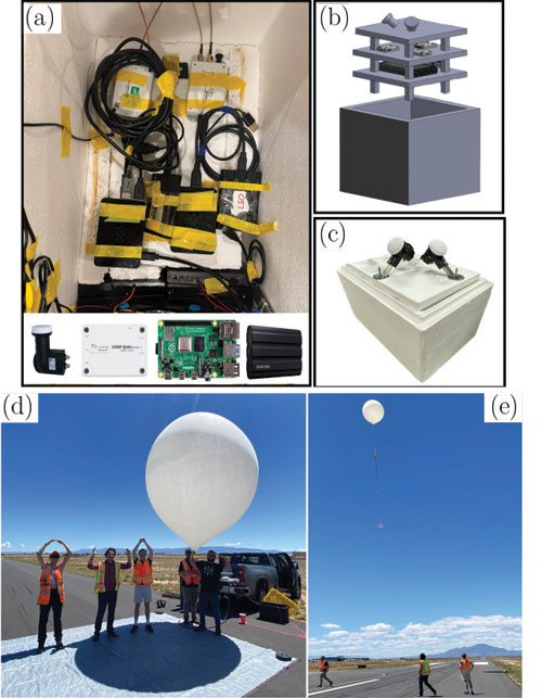
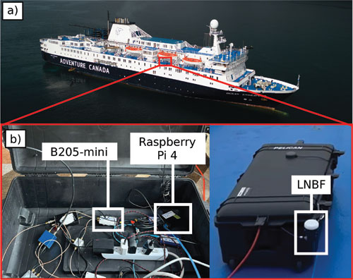
    The authors would like to thank Vasilios Konstantacos, Jackson Morris, Ethan Shaw, Khaled Hamil, Aiden Short and Andrew Ye for constructing the balloon’s payload; Mark Andrews for supervising the payload design; and Prabodh Jhaveri, Danny Bowman, Mike Fleigle and Justin LaPierre for helping with launch and recovery of the balloon. The authors would also like to thank The Explorers Club and Adventure Canada for their help with data collection in the Arcitc. The authors would like to thank VectorNav for supplying the VN-200.

    References

    1. A. Yadav, M. Agarwal, S. Agarwal, and S. Verma, “Internet from space anywhere and anytime – Starlink,” in Proceedings of International Conference on Advancement in Electronics & Communication Engineering, pp. 1-8, 2022.

    2. J. Morales, J. Khalife, A. Abdallah, C. Ardito, and Z. Kassas, “Inertial navigation system aiding with Orbcomm LEO satellite Doppler measurements,” in Proceedings of ION GNSS+ Conference, pp. 2718-2725, 2018.

    3. Z. Kassas, J. Morales, and J. Khalife, “New-age satellite-based navigation – STAN: simultaneous tracking and navigation with LEO satellite signals,” Inside GNSS Magazine, (14)4, pp. 56-65, 2019.

    4. M. Neinavaie, J. Khalife, and Z. Kassas, “Exploiting Starlink signals for navigation: first results,” in Proceedings of ION GNSS+ Conference, pp. 2766-2773, 2021.

    5. J. Khalife, M. Neinavaie, and Z. Kassas, “The first carrier phase tracking and positioning results with Starlink LEO satellite signals,” IEEE Transactions on Aerospace and Electronic Systems, (58)2, pp. 1487-1491, 2022.

    6. M. Neinavaie, J. Khalife, and Z. Kassas, “Acquisition, Doppler tracking, and positioning with Starlink LEO satellites: first results,” IEEE Transactions on Aerospace and Electronic Systems, (58)3, pp. 2606-2610, 2022.

    7. Z. Kassas, M. Neinavaie, J. Khalife, N. Khairallah, S. Kozhaya, J. Haidar-Ahmad, and Z. Shadram, “Enter LEO on the GNSS stage: navigation with Starlink satellites,” Inside GNSS Magazine, (16)6, pp. 42-51, 2021.

    8. T. Humphreys, P. Iannucci, Z. Komodromos, and A. Graff, “Signal structure of the Starlink Ku-band downlink,” IEEE Transactions on Aerospace and Electronic Systems, (59)5, pp. 6016-6030, 2023.

    9. M. Neinavaie and Z. Kassas, “Cognitive sensing and navigation with unknown OFDM signals with application to terrestrial 5G and Starlink LEO satellites,” IEEE Journal on Selected Areas in Communications, (42)1, pp. 146-160, 2024.

    10. S. Hayek and Z. Kassas, “Warm start navigation with non-cooperative LEO satellites via online ephemeris error estimation,” in Proceedings of IEEE/ION Position, Location, and Navigation Symposium, pp. 112-123, 2025.

    11. W. Qin, A. Graff, Z. Clements, Z. Komodromos, and T. Humphreys, “Timing properties of the Starlink Ku-band downlink,” IEEE Transactions on Aerospace and Electronic Systems, (62), pp. 727-744, 2026.

    12. H. More, E. Cianca, and M. De Sanctis, “Comparing positioning performance of LEO mega-constellations and GNSS in urban canyons,” IEEE Access, (12), pp. 24465-24482, 2024.

    13. Z. Kassas and J. Saroufim, “LEO PNT frameworks for non-cooperative satellites with poorly known ephemerides: open-loop SGP4, tracking, and differential,” IEEE Aerospace and Electronic Systems Magazine, (40)1, pp. 46-71, 2025.

    14. S. Kozhaya, H. Kanj, and Z. Kassas, “Multi-constellation blind beacon estimation, Doppler tracking, and opportunistic positioning with OneWeb, Starlink, Iridium NEXT, and Orbcomm LEO satellites,” in Proceedings of IEEE/ION Position, Location, and Navigation Symposium, pp. 1184-1195, 2023.

    15. S. Kozhaya, S. Hayek, and Z. Kassas, “Cognitive beacon estimation of unknown LEO satellites signals of opportunity for PNT,” IEEE Journal on Selected Areas in Communications, pp. 1-16, 2026, in-press.

    16. S. Kozhaya, J. Saroufim, and Z. Kassas, “Unveiling Starlink for PNT,” NAVIGATION, Journal of the Institute of Navigation, (72)1, pp. 1-35, 2026.

    17. J. Khalife and Z. Kassas, “Performance-driven design of carrier phase differential navigation frameworks with megaconstellation LEO satellites,” IEEE Transactions on Aerospace and Electronic Systems, (59)3, pp. 2947–2966, 2023.

    18. M. Hasan, M. Kabir, M. Islam, S. Han, and W. Shin, “A double difference Doppler shift-based positioning framework with ephemeris error correction of LEO satellites,” IEEE Systems Journal, (18)4, pp. 2157-2168, 2024.

    19. Z. Kassas, S. Hayek, and J. Haidar-Ahmad, “LEO satellite orbit prediction via closed-loop machine learning with application to opportunistic navigation,” IEEE Aerospace and Electronic Systems Magazine, (40)1, pp. 34-49, 2024.

    20. K. Selvan, A. Siemuri, F. Prol, P. Välisuo, and H. Kuusniemi, “Machine learning for LEO and MEO satellite Orbit prediction,” in Proceedings of ION GNSS+ Conference, pp. 3556 -3571, 2024.

    21. J. Saroufim and Z. Kassas, “Ephemeris and timing error disambiguation enabling precise LEO PNT,” IEEE Transactions on Aerospace and Electronic Systems, (61)3, pp. 6138–6153, 2025.

    22. J. Saroufim and Z. Kassas, “LEO ephemeris error modeling enabling long baseline correction for improved PNT,” in Proceedings of IEEE/ION Position, Location, and Navigation Symposium, pp. 625–630, 2025.

    23. N. Khairallah and Z. Kassas, “Ephemeris tracking and error propagation analysis of LEO satellites with application to opportunistic navigation,” IEEE Transactions on Aerospace and Electronic Systems, (60)2, pp. 1242–1259, 2024.

    24. S. Kozhaya, J. Saroufim, S. Hayek, P. El-Kouba, and Z. Kassas, “Light will guide you: passive joint DOA/FOA sensing, tracking, and navigation with unknown LEO satellites,” in Proceedings of IEEE/ION Position, Location, and Navigation Symposium, pp. 716–727, 2025.

    25. Y. Du, H. Qin, and C. Zhao, “LEO satellites/INS integrated positioning framework considering orbit errors based on FKF,” IEEE Transactions on Instrumentation and Measurement, (73), pp. 1-14, 2024.

    26. S. Hayek, J. Saroufim, and Z. Kassas, “Analysis and correction of LEO satellite propagation errors with application to navigation,” in Proceedings of ION GNSS+ Conference, pp. 1800 -1811, 2024.

    27. S. Hayek and Z. Kassas, “Modeling and compensation of timing and spatial ephemeris errors of non-cooperative LEO satellites with application to PNT,” IEEE Transactions on Aerospace and Electronic Systems, (61)3, pp. 5579-5593, 2025.

    28. S. Hayek and Z. Kassas, “A reduced-order model of simultaneous tracking and navigation with LEO satellites”, IEEE Aerospace and Electronic Systems Magazine, in preparation.

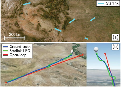
    29. W. Barrett, J. Sanderson, S. Kozhaya, J. Saroufim, and Z. Kassas, “Evaluation of Starlink LEO satellite signals for high-altitude platform station opportunistic navigation,” in IEEE International Conference on Wireless for Space and Extreme Environments, pp. 100-105, 2024.

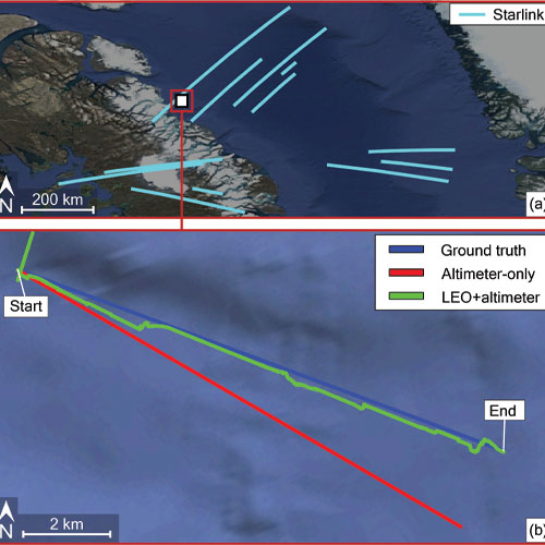
    30. W. Barrett, S. Kozhaya, Z. Kassas, and D. Marsh, “Navigating the Arctic Circle with Starlink and OneWeb LEO satellites,” in Proceedings of IEEE Military Communications Conference, pp. 1–6, 2025.

    Authors

    Zaher (Zak) M. Kassas is the TRC Endowed Chair in Intelligent Transportation Systems and Professor of Electrical and Computer Engineering at The Ohio State University (OSU). He is also Director of the Autonomous Systems Perception, Intelligence, & Navigation (ASPIN) Laboratory and Director of the U.S. Department of Transportation Center for Automated Vehicles Research with Multimodal AssurEd Navigation (CARMEN).

    Samer Hayek is a Ph.D. student at OSU and member of the ASPIN Laboratory.

    Will Barrett was a member of the ASPIN Laboratory.

    Sharbel Kozhaya is a Senior Research Associate at the ASPIN Laboratory.

    Paul El-Kouba is a Ph.D. student at OSU and member of the ASPIN Laboratory.

    Faezeh Mooseli is a Ph.D. student at OSU and member of the ASPIN Laboratory.

    Jennifer Sanderson is a Ph.D. student at OSU and member of the ASPIN Laboratory. She is also an R&D Engineer with Sandia National Laboratories.

    Joe Saroufim is a Ph.D. student at OSU and member of the ASPIN Laboratory.

  • The latest on defense/PNT product developments

    The latest on defense/PNT product developments

    1. Anti-jamming antenna

    For defense, marine and critical infrastructure 

    Photo: Calian, GNSS
    Photo: Calian, GNSS

    The CR8894SXF+ is an advanced controlled reception pattern antenna (CRPA) for anti-jamming. It is engineered to provide efficient interference protection and real-time situational awareness across critical infrastructure, marine and defense environments where GNSS continuity is mission critical. It is specifically designed to provide a low-power and lightweight solution in a compact size. It features advanced in-band null forming to protect GPS L1/L2 and Galileo E1/E5b signals, helping ensure resilient positioning, navigation and timing in environments with contested, congested or degraded radio frequency conditions. The antenna incorporates Calian’s eXtended Filtering interference mitigation technology to maintain performance and reliability when RF threats are present. The CRPA supports in-band null-forming of 20 dB to 40 dB and out-of-band rejection up to 80 dB across 700 MHz to 2,500 MHz. It includes two independent low-noise amplifier channels, allowing continued operation if one signal band is compromised. The antenna forms nulls in both upper (L1/E1) and lower (L2/E5b) GNSS bands to actively suppress jamming sources. A serial output interface provides real-time feedback, enabling users to monitor RF conditions and system status. 

    Calian GNSS, calian.com

    2. PNT System

    Integrates GNSS receiver, INS, atomic clock 

    Photo:
    Photo: Safran Electronics & Defense

    The BlackNaute autonomous positioning, navigation and timing (PNT) system integrates Safran’s HRG dual-core inertial navigation technology, the Skylight multi-mode GNSS receiver board, and an atomic clock to offer navigation resilience in challenging electronic warfare environments. BlackNaute’s built-in atomic clock is designed to maintain precise timing, which is essential for secure communications and collaborative combat operations. The system features advanced anti-jamming and anti-spoofing algorithms, which have been validated in more than 16,000 operational cases. These capabilities allow BlackNaute to detect compromised signals and automatically switch to autonomous and trusted navigation and timing sources to ensure continuity of operations. Its modular design allows it to be adapted across a variety of platforms. Airbus Helicopters has selected the NH90 to be equipped with this new Embedded GNSS and Time INS (EGTI). 

    Safran Electronics & Defense, safran.com

    3. Interference detection

    Suite enhanced for greater accuracy, coverage and insight 

    Photo:
    Photo: US Navy

    HawkEye 360’s GNSS-I Detection suite includes powerful enhancements to its GNSS interference detection capabilities. The upgrades — designed with defense, intelligence and national security operations in mind — offer unprecedented accuracy, coverage and insight into global GPS jamming and spoofing threats. The update includes a new wider frequency algorithm that better distinguishes individual emitters, incorporates GPS spoofing detection, and is terrain adjusted for better geolocation accuracy, delivering greater situational awareness and more precise geolocation of interference sources worldwide. The enhanced product suite supports strategic decision-making by providing timely, precise insight into potential signal disruptions, enabling stakeholders to better assess risk, respond confidently, and maintain operational continuity in dynamic environments.

    HawkEye 360, he360.com

    4. VTOL UAS

    For complex intelligence, surveillance and reconnaissance missions 

    Photo: ESEN-UAS
    Photo: ESEN-UAS

    The GöKHUN unmanned aerial system (UAS) is a tactical vertical take-off and landing (VTOL) drone system developed for versatile missions on land or at sea. GöKHUN combines the compact mobility of a NATO Class I UAV with the performance data of a Class II tactical system. It uses the SP 210 FI GS 2-stroke engine from Sky Power International. With a take-off weight of up to 110 kg and a maximum fuel and payload capacity of 26 kg, the GöKHUN can remain in the air for up to 16 hours with a minimum payload. Even with a demanding sensor load of 12 kg, it can achieve a flight duration of around nine hours, making it suitable for long-endurance reconnaissance and surveillance missions. The GöKHUN’s cruising speed is between 96 and 158 km/h. The maximum range with direct line-of-sight is over 150 km, with the system reaching a service ceiling of approximately 5,500 m.

    ESEN, esensi.com.tr 

  • TSR unveils tactical drone system with 3-hour flight time

    TSR unveils tactical drone system with 3-hour flight time

    TSR Inc. (Tactical Surveillance Reconnaissance) has launched the AVRIO series autonomous drone systems — cutting-edge European-made unmanned aircraft designed to redefine aerial surveillance, reconnaissance, and precision-strike capabilities.

    The AVRIO family, which includes the Falcox and Nebris platforms, delivers unmatched performance and resilience for defense, security and critical infrastructure missions, according to TSR. The company designed the AVRIO series for a wide range of defense and homeland-security missions, including:

    • Border security and coastal defense
    • Rapid-response reconnaissance and force protection
    • Counter-UAS operations using RF seeker payloads
    • Critical infrastructure protection and disaster-response intelligence.

    “The AVRIO series combines European aerospace engineering with U.S.-based deployment and support, giving governments and security agencies a next-generation toolset for ISR and tactical defense,” said Rick Clarke, CEO of Safe Room Designs/TSR Inc. “This is autonomous aerial defense, reinvented.”

    Specifications of the AVRIO

    • ISR (intelligence, surveillance, reconnaissance). Real-time EO/IR video, day/night operations, target tracking and identification.
    • Quick-launch and versatility. Vertical takeoff and landing, <1-minute preparation, runway-independent operation, and mission abort/return-to-base features.
    • Extended reach. Endurance of up to three hours and a range of up to 30 km, depending on payload and mission configuration.
    • Precision engagement. Options for smart munition payloads with precision super-quick impact fuzes and effective 15 m radius, plus anti-personnel and armor-piercing warheads.
    • Resilient design. Low radar cross section, GNSS-denied operation, MIL-STD-810G-qualified ground control, and operational temperature from –20 °C to +50 °C.
    • Naval and special missions. Capable of surface-mine detection, sweeping operations, and beyond-line-of-sight (BLOS) intelligence gathering.

    TSR is now accepting government and defense-sector inquiries for the AVRIO Falcox and AVRIO Nebris systems. For detailed specifications, demonstrations, or procurement discussions, contact TSR.

  • Honeywell, U.S. Army to deliver next-gen navigation solution

    Honeywell, U.S. Army to deliver next-gen navigation solution

    On Jan. 9, Honeywell announced it is ready to deliver its EAGLE-M Embedded Global Positioning System/Inertial Navigation System (EGI) with M-code capabilities this year, after the United States Army completed the first test flight.

    The Army tested the EGI units with enabled M-code on the MQ-1C Gray Eagle unmanned aerial system and validated it to be deployed on military aircraft. This year, the Army will begin migrating its fleet to the Honeywell EAGLE-M EGI with M-code, as this navigation solution enhances the resiliency of GPS navigation to enemy actions.

    Photo:
    Image: Honeywell

    The defense technology company has delivered more than 300 EGIs with M-code to customers and will deliver qualified units, featuring M-code GPS, to the Army. Honeywell is a leader in EGI for military applications and has provided more than 45,000 EGI units for several different types of aircraft in more than 30 countries.