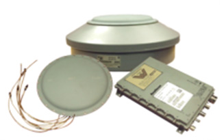
Hemisphere’s Atlas-enabled Platinum VADER smart antenna.
Plantium, in Santa Fe, Argentina, is a full-service provider of precision agricultural guidance systems to some of Argentina’s largest farming operations.
The company makes its own guidance and control devices, installs them and offers farmers real-time, remote support if required. Plantium uses the Atlas GNSS Global Correction Service as the primary means of providing precise, real-time location corrections to its customers, and their receivers are based on Atlas-ready OEM boards from Hemisphere GNSS.
“We design, manufacture and sell precision agriculture systems,” said Federico Baulies, robotics engineer for Platinum. “As a part of our SBOX7 + DirectDrive + VADER system, Atlas really helps with all of these. Atlas tools give us the ability to diagnose and solve problems in real-time — probably its best feature.”
“As soon as we hear of an issue, from operators or from alarms built into our monitors, we can collect several working variables — such as interference and satellite noise — immediately, from our offices, and diagnose many problems instantly,” Baulies explained.
Argentine farmers benefit from remote problem-solving with the Hemisphere Atlas-enabled Platinum VADER smart antenna.
“That means we do not have to wait for 30 minutes to see if our client will get convergence — we know right away. A lot of that capacity is built right into the Hemisphere OEM boards or from the way the Atlas service is designed.
“These diagnostic tools also help on the customer’s end,” Baulies said. “The Atlas service and Hemisphere’s OEM boards make clear user interfaces possible, and end users are rarely confused about the state of their equipment.”
Once a problem is diagnosed, Plantium engineers can implement fixes quickly, using cellular connectivity.
“We can often diagnose and fix a problem remotely, sometimes in the same phone call,” Baulies said.
The Trimble Catalyst software-defined GNSS receiver for Android devices is now available through Trimble’s global distribution network.
Trimble Catalyst DA1 antenna attaches to a smartphone running a Catalyst-enabled app.
Through Catalyst and a special antenna, customers can access positioning-as-a-service to collect geolocation data with Trimble or third-party apps on smartphones, tablets and mobile handhelds.
When combined with a plug-and-play digital antenna and subscription to the Catalyst service, the receiver provides on-demand GNSS positioning capabilities to turn consumer Android devices into centimeter-accurate data-collection systems.
Catalyst requires only a few components:
Any location-enabled mobile app.
A Catalyst subscription, with accuracy options ranging from one meter to centimeter level.
Trimble’s small, lightweight DA1 antenna that plugs directly into Android smartphones and tablets.
“Our goal has always been to extend the accessibility of high-accuracy positioning to a broader base of geospatial and non-geospatial professionals,” said Ron Bisio, vice president of Trimble Geospatial. “Trimble Catalyst represents a new era of GNSS technology by making high-precision positioning a reality for new user segments around the world. With economical on-demand service, it puts high-accuracy in the palm of anyone’s hand — it’s revolutionary.”
Both Trimble and third-party development teams have produced a range of Catalyst-enabled applications for geographic information system (GIS) data acquisition, cadastral land management, topographic mapping and ground control for unmanned aircraft systems (UAVs).
Also, the Trimble Catalyst solution includes a software development kit (SDK) for building mobile applications with integrated professional workflows.
“Trimble is enabling us to deliver better solutions for our customers thanks to the level of integration that the SDK provides,” said Paul Brodin of Korec Group. “It allows us to provide sophisticated solutions that are innovative, easy to use and remove the technical complexity associated with high-accuracy workflows.”
Trimble Catalyst service subscriptions and the Catalyst DA1 antenna are now available through Trimble’s Authorized GIS Distribution Network. Catalyst availability, pricing, subscription and accuracy may vary by region. Catalyst-enabled apps for Android can be found in the Google Play Store.
In my April column, I introduced the basic concepts behind GPS anti-jam technology, along with a bit of history around its evolution. I knew this was a popular topic, but I didn’t anticipate the enormous amount of positive correspondence I’ve received since, including many inquiries about where to buy this technology and who is entitled to have it.
So this month we return to the controlled reception pattern antenna (CRPA) topic, to look specifically at the major suppliers of GNSS anti-jam technology in a bid to help you select the best fit for your requirements.
As mentioned in April, CRPAs can trace their roots back to military radar developments in the 1970s and 1980s. It’s no surprise, then, that the main players in the CRPA market tend to be large defense primes. But there are many smaller companies, universities and research institutions that also play in the CRPA arena these days.
What about export?
When GNSS jamming was a little-known military problem, the situation was simple: anti-jam was a military technology for military applications only. Later, as GPS evolved into a dual-use technology, critical infrastructure and civilian applications brought a new demand for anti-jam in non-military domains.
Confusion then abounded about who exactly is entitled to make use of anti-jam technology. There are two distinct factors here: security classification, and export control. Let’s clear these up.
Security classification is simple: If a product is classified, it is only available to customers who hold the appropriate level of security clearance. Usually it is the performance and vulnerabilities of a product that would attract a classified status. As you might expect for in-service military products, the military would not wish everyone to know the performance and weaknesses of its deployed technology. This is why many datasheets for CRPAs omit performance information.
The second issue is export control. This, of course, varies by country. In the U.S., a CRPA developed towards a defense program is likely to have International Traffic in Arms Regulations (ITAR) restrictions attached to it. In Canada, CRPAs are subject to the Controlled Goods Program. In the UK, CRPAs sit on the “dual-use” export control list, which recognizes that CRPAs have both military and non-military application. An export license is usually required.
Before I go any further, a little disclaimer: I am not making any product recommendations in this article. There are many things to consider when choosing anti-jam technology, and you should always consult a navigation warfare expert and carry out appropriate evaluations prior to choosing a product. You should also seek guidance from your own government regarding any restrictions on export or import.
With that out of the way, let’s look at the offerings of a few suppliers. This is by no means a complete list, but I did manage to catch up with a few of the major players to ask them about their anti-jam technology offerings.
NovAtel
I spoke with Peter Soar, business development manager, Military and Defence, at NovAtel about NovAtel’s offerings.
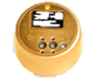
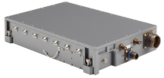
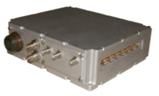
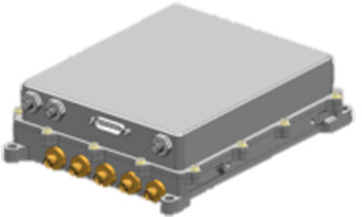
Peter Soar: “The GAJT-710 series are retrofittable GPS anti-jam products that combine a seven-element controlled reception pattern antenna (CRPA) and the antenna electronics in a single unit. The GAJT-AE-N is a GPS anti-jam antenna electronics system that supports a separated four-element antenna.”
Photo: NovAtel
Photo: NovAtel
Photo: NovAtel
Main features: “All three products protect the GPS L1 and L2 bands simultaneously, and are suitable for military (SAASM) receivers as well as open-signal receivers, normal civil receivers and ‘survey grade’ receivers. The wideband design means that the units are ready for M-code. In the GAJT-710, there are seven antenna elements for up to six independent nulls on both frequencies, and the GAJT-AE-N supports four antenna elements, for up to three independent nulls. All products use space-frequency adaptive processing for increased degrees of freedom. System messages provide an indication of jamming presence, even when the nulling is defeating the jamming.”
Intended market: “GAJT-710ML is optimized for land use, while GAJT-710MS is used for maritime and littoral applications. Both types are currently in use on mobile platforms and fixed installations. The GAJT-AE-N is optimized for smaller platforms such as unmanned air vehicles, and is currently in use on a variety of platforms. GAJT products have been shipped to customers in 16 countries to date.”
Example customers: “The GAJT-700ML (a predecessor to the 710ML) was selected for trials by the Canadian Army through the Build in Canada Innovation Program, with exercises performed on the Artillery Observation Post Vehicle (LAV III OPV). Both GAJT variants were selected for field testing by the U.S. Army Communication-Electronics Research Development and Engineering Center (CERDEC) through the U.S. Army Rapid Innovation Fund. The United States Naval Observatory (USNO) selected the GAJT-710ML to satisfy a requirement at sites throughout the Department of Defense Information Network (DoDIN). The GAJT-AE-N is deployed on the Schiebel Camcopter S-100, and was also selected for testing on the M777C1 Howitzer by the Canadian Army.”
Situation with regards to export: “All GAJTs are designed and built in Canada. As such, they are subject to the Controlled Goods Program of Canada, but they are free from ITAR for non-U.S. customers.”
Raytheon UK
Some Raytheon products were mentioned briefly in the April column; I caught up with Alan Wright, business development executive, Force Protection, to get the latest information.
Alan Wright: “Raytheon UK offers a range of anti-jamming products ranging from high-performance products with multiple-element CRPAs to low size, weight and power products. Our current product lines utilize either analog or digital technologies to suit specific end-user requirements.”
Product
Image
Key Features
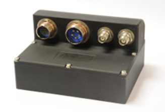
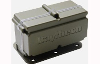
GAS-1
Analog technology, 7 antenna elements, switchable L1/L2 protection, minimal quiescent time delay, nulling, J/N, M-code signal bandwidth, AE/antenna integrated variant, fiber optic output variant.
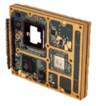
Digital technology, 5 antenna elements, simultaneous L1/L2 protection, low size, weight & power, STAP, nulling, J/N, direction finding, anti-spoof, jamming flag, M-code signal bandwidth.
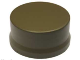
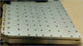
Landshield
Digital technology, integrated 4-element antenna, simultaneous L1/L2 protection, low size, weight and power, STAP, nulling, J/N, direction finding, anti-spoof, jamming flag, M-code signal bandwidth, switched antenna variant.
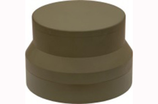
MiniGAS
Analog technology, integrated 4-element antenna, simultaneous L1/L2 protection or L1 with L2 passthrough, low size, weight and power, minimal quiescent time delay, nulling, jamming flag.
MicroGAS
Analog technology, integrated 2-element antenna, simultaneous L1/L2 protection, very low size, weight and power, minimal quiescent time delay, nulling.
Intended market: “With over 25 years’ experience, Raytheon UK is a world leader in the development, production and supply of GPS Anti-Jamming (GPS-AJ) systems to the majority of the world’s military forces (including the U.S. DoD and UK MOD), with solutions developed and certified for air, maritime and land applications. Raytheon UK has designed and manufactured in excess of 10,000 GPS anti-jam units for the worldwide market.”
Situation with regards to export: “GAS-1, ADAP and SAS are subject to U.S. ITAR restrictions. Landshield, MiniGAS and MicroGAS are free from ITAR and subject to UK export control.”
Rockwell Collins
I spoke with Al Simon, business development for navigation products/solutions, to get the latest on Rockwell Collins’ offerings. Rockwell’s portfolio includes some CRPA products aimed specifically at weapons. Al kindly provided the following table to summarize:
Product
Image
Platform
Key Features
Integrated GPS Anti-Jam System (IGAS)
Weapons (Embedded)
GPS receiver + AJ, nulling and beamforming, spatial, 20 in3, <2 lbs, up to 4 RF antenna inputs, 90+ dB J/S performance *, GPS (simultaneous L1 & L2), path to M-code
Strategic Anti-Jam Beamforming Receiver (SABR)
Weapons (Embedded)
GPS receiver + AJ, nulling and beamforming, STAP, 46 in3, <3 lbs, up to 7 RF antenna inputs, 120+ dB J/S performance*, GPS (simultaneous L1 & L2), path to M-code
NavStorm+
Weapons
Nulling, spatial, 6.9 in3, <.6 lbs, up to 5 RF antenna inputs, 20,000 G shock, 90+ dB J/S performance*, GPS (simultaneous L1 & L2), path to M-code
NavFire
Weapons
Nulling, spatial, 2 in3, <.2 lbs, 1 or 2 RF antenna inputs, 25,000 G shock, 85+ dB J/S performance*, GPS (L1 or L2), path to M-code
DIGAR-200
Airborne, Maritime, Ground
Nulling and beamforming, spatial, 218 in3, <11 lbs, up to 7 RF antenna inputs, 110+ dB J/S performance*, GPS (simultaneous L1 & L2), path to M-code
DIGAR-300
Airborne, Maritime, Ground
Nulling and beamforming, STAP/SFAP, 69 in3, <5 lbs, up to 7 RF antenna inputs, 125+ dB J/S performance *, GPS (simultaneous L1 & L2), path to M-code
Small Platform AJ (Pre-Production)
Ground, Airborne
Nulling and beamforming, STAP/SFAP, 45 in3, <3 lbs, up to 7 RF antenna inputs, 95+ dB J/S performance*, GPS (simultaneous L1 & L2), path to M-code
STAP (Space Time Adaptive Processing); SFAP (Space Frequency Adaptive Processing)
* Beamsteering mode. Actual performance is classified
Situation with regards to export: All listed products are unclassified, but are subject to U.S. ITAR restrictions.
Roke Manor Research
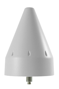
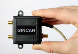
This column wouldn’t be complete without a few words on my own organization. Roke has been developing anti-jam CRPAs since the 1980s, but rarely offers its own products. Typically Roke develops bespoke anti-jam and anti-spoof technology for other defense organizations, including for some products already listed above. Examples of bespoke developments for more specialist markets include Gincan and the Helium antenna.
Photo: Roke
Photo: Gincan
Main features: Both these products are aimed at the commercial civilian market, but do also have defense interest. The Gincan is a very basic low-cost CRPA, with just two antenna elements. The Helium is a conical spiral design, using four antenna elements, and is primarily aimed at protecting GNSS in critical infrastructure. The Helium has excellent low-elevation performance. Both antennas feature very low latency, making them particularly suitable for timing receivers.
Intended market: The Gincan is primarily aimed at providing a basic level of anti-jam capability to the automotive mass market, including cars and trucks, but also has been adopted by some lightweight UAV platforms. The Helium is aimed directly at timing receivers for critical infrastructure, including mobile base stations, digital TV networks, stock exchange and financial institutions, and power and utility grids.
Example customers: Gincan has been delivered to 42 countries, with a mixture of commercial, defense and national security customers. Helium is a relatively new product, and is being trialed on infrastructure in two countries.
Situation with regards to export: Both products are unclassified and suitable for commercial use. They are subject to UK export control as dual-use items, and are ITAR-free.
Others
There are many other suppliers of CRPA technology — unfortunately, too many to cover in this column. Mayflower Communications offer a good range of CRPA products in the form of their NavGuard range. Some other suppliers include Cobham Antenna Systems, BAE Systems Rokar, Thales, Harris Corporation, L-3 Interstate Electronics and Lockheed Martin. I encourage you to contact these companies for the latest information if you are contemplating a CRPA product. If you’re a CRPA supplier and I’ve missed you, please feel free to post a link to your products in the comments section below.
So, that was a bit of a whirlwind tour through some of the products currently around. CRPAs come in all shapes and sizes, and they all have their own particular characteristics and subtleties.
I conclude by reiterating my earlier point. Always conduct a threat analysis, seek the help of a navigation warfare expert if necessary, and properly evaluate your choices. Happy choosing!
Taoglas has launched Axiom, a reference design for a low-profile, compact multiple-antenna solution for the next generation of connected cars. Taoglas is a provider of GNSS, automotive and Internet of Things products.
The reference design will help automobile manufacturers overcome one of the biggest challenges of the connected car: where and how to place the multitude of antennas needed for maximum performance.
As many as 18 antennas are needed to power the next-generation connected car, including
multiple cellular antennas for network connectivity;
Wi-Fi for hotspot connectivity;
GNSS for navigation, emergency call systems and other location-based technologies;
satellite radio;
AM/FM antennas;
radar antennas for object detection;
Bluetooth antennas for smartphones and other devices, and
dedicated short-range communications (DSRC) antennas for vehicle-to-vehicle/infrastructure applications.
Locating these antennas in a vehicle in close proximity to each other and additional electronics systems while minimizing interference and maximizing performance is extremely challenging from a design and RF performance perspective.
Manufacturers also need to take into consideration both ease of installation and assembly, and antenna size to determine how they would best work with the vehicle’s aesthetics. Taoglas has worked with the automotive industry for more than a decade, providing antenna solutions to many of the major tier 1 automobile OEMs across the globe.
The Axiom reference design incorporates Taoglas’ wealth of knowledge and expertise gained over the years into a roadmap to help automobile manufacturers more quickly advance antenna configurations that work for their particular make and model.
“Getting that many antennas to work efficiently in a small space at a competitive cost is the number one challenge for the RF teams of automobile manufacturers,” said Dermot O’Shea, co-CEO of Taoglas. “While every car manufacturer will require a slightly different solution, having a multi-antenna reference design to work from allows them to see what they can do in terms of placement and size, and how that impacts performance — all without waiting months for a custom solution to test. They can take the prototype and test it in the field to prove out concepts. Using Taoglas’ Axiom reference design allows them move more quickly to market with solutions that work. We can also work with Tier 1 OEMs to integrate the elements of the Axiom antenna reference design quickly and efficiently directly onto the board of their telematic control units, achieving highest radiated power and sensitivity, while minimizing project time, cost and size, all in one single package.”
Taoglas’ Axiom reference design has integrated nine antennas, including:
LTE Antennas: Four LTE antennas, each operating from 698 MHz to 6 GHz to fully cover LTE worldwide application bands.
Wi-Fi Antennas: Two Wi-Fi elements, supporting both 2.4 GHz and 5.8 GHz bands for Wireless Local Area Network.
GNSS Antenna: An active GNSS element to support GPS, GLONASS and BeiDou navigation systems. L1/L2 options available.
SDARS Antenna: One SDARS element to support satellite radio applications.
DSRC Antenna: One DSRC element, which supports V2V/V2X dedicated short range communication.
Taoglas’ advantage is its ability to integrate all of the antennas required for the connected car in a confined space and maintain maximum performance. The Axiom reference design uses a compact PCB all with SMT-mounted components, and also incorporates a unique board-to-board connector option, allowing the antennas and electronics systems to coexist in a single space inside the vehicle, with no RF cables or additional connectors required.
The Axiom reference design also helps auto manufacturers simplify manufacturing and assembly, with surface-mount solutions that feature the temperature and vibration resistance with the quality standards that manufacturers require. Installation is clipping the PCB into the telematics board.
Oscilloquartz has launched the OSA 5405 SyncReach, an integrated PTP grandmaster and GNSS receiver with a patent-pending dual antenna and receiver to enable the mass roll out of small cells.
The new technology has been specifically engineered to provide accurate and affordable phase synchronization for the rapidly growing small-cell market and meet the stringent timing requirements of 4.5G and 5G connectivity.
With the OSA 5405, operators can migrate from legacy GNSS RF antennas and cables to standard, cost-effective copper and fiber Ethernet cabling, reducing capital expenditure and operating expenses, Oscilloquartz said.
Available in both indoor and outdoor variants, the OSA 5405 can be deployed in challenging environments, including urban canyons where GPS signals fail. The OSA 5405’s miniscule form factor also enables it to be positioned on indoor windows to avoid multipath signal interference from objects within the building.
The OSA 5405 uses a unique dual GNSS antenna and receiver algorithm to mitigate interference from multipath signals that can affect accuracy, particularly in urban canyons, according to the company.
“We’re at the start of a new era. With the internet of things (IoT) connecting more wireless devices and 5G just around the corner, small cells will have a big role to play,” said Gil Biran, general manager at Oscilloquartz. “This market is set to grow exponentially in the next few years. Small cells will soon be everywhere and that makes precise synchronization essential. Operators urgently need a way to reliably and affordably deliver new levels of phase accuracy.
“We’ve created our OSA 5405 to effectively deliver small cell synchronization in any environment and eliminate all restrictions,” Biran said. “Our new technology radically simplifies GNSS antenna installation. The use of PTP removes the need to compensate for cable delay and extends the reach of GNSS. It enables operators to forget about archaic and expensive RF cables and use simple copper cabling or optical fiber for longer distances. And, with variants that can be positioned in almost any location, it provides strictly accurate timing precisely where it’s needed.”
The compact design and power-over-Ethernet capabilities of the indoor- or outdoor-mounted OSA 5405 enable synchronization at the edge of the mobile network. This creates dramatic reductions in complexity and power requirements as well as lower costs for installation and operation.
Another feature of the new technology is IP connectivity, so that synchronization becomes another element of the internet of things.
The OSA 5405’s highly precise GNSS-sourced synchronization is supported by network-based Sync-E and PTP backups. In high-rise buildings it can also deliver synchronization recovered from the GNSS smart receiver over optical fiber.
The ADVA FSP Network Manager with comprehensive Syncjack assurance guarantees efficient operation.
“Make no mistake; the launch of our OSA 5405 is a major milestone in the progress towards mass-scale small cell deployment,” said Nir Laufer, product line director at Oscilloquartz. “With its plug-and-play simplicity, miniscule form factor and multiple timing functions in a single device, this is a key technology for 5G networks and the IoT.
“Currently deployed in trials with major carriers, it will shortly be available to all operators looking to harness next-generation synchronization precisely where it’s needed,” Laufer said.
Taoglas, a provider of Internet of Things (IoT) and GNSS antenna products, has released two new GPS certification testing services for Google and its device partners. The services are required for devices to meet Google’s new Street View auto-ready standard.
Auto-ready certification distinguishes 360-degree cameras that deliver accurately positioned 360 video, even at high speeds. Taoglas worked with Google to develop the performance requirements, as well as the test methodology used to establish a basic minimum level of GPS receiver performance.
The services are available at any of Taoglas’ design centers and labs in the United States, Ireland, Germany and Taiwan.
Compact wireless devices such as digital cameras with built-in GPS receiver systems contain complex electronic systems that can emit unwanted RF signals that can impact radio receiver performance. The effect of this RF noise can be combated with critical design decisions like the antenna, low noise amplifier, filters, and transmission line choice and implementation.
Taoglas’ new services will help device manufacturers objectively measure real-world performance to understand any GPS performance issues with their products. With this information, product manufacturers will know if their performance is optimized and will meet or exceed user expectation for the application at hand, as well as how it compares with their competitors.
“Google Street View provides people with a 360-degree view of the world, and to enable these services, we require highly accurate location data,” said Charles Armstrong, product manager at Google. “By working with Taoglas to establish a standardized compliance process, we’re helping device manufacturers understand our requirements for GPS performance and quickly deliver products that match and exceed those high performance standards.”
Taoglas is offering two levels of certification testing:
Street View Auto-Ready Conformance Testing (GSA.31) provides a quick verification of minimum performance (in a pass/fail manner) required to achieve Street View certification. Taoglas uses its GPS constellation simulator and anechoic chamber to verify that radiated tracking and acquisition sensitivity meet a minimum performance standard at 15-degree intervals in one hemisphere.
From these test results, manufacturers will be able to clearly see if the device’s GPS is performing adequately for basic location capabilities. The condensed period needed to run this test provides device manufacturers the best value to answer the question, “Is the GPS working optimally?”
A street view image of Guatemala. (Credit: Google)
Street View Auto-Ready Performance Testing (GSA.32) provides an absolute level of testing to assess the GPS receiver performance according to the optional Google Street View Assessment test procedures.
Taoglas uses its GPS constellation simulator and anechoic chamber to measure radiated tracking and acquisition sensitivity at 15-degree intervals in one hemisphere. These optional tests provide more insight into how well a device performs, providing absolute receive sensitivity performance data.
Testing results for both services include suggestions on next steps to resolve identified issues.
“This partnership with Google to deliver GPS testing solutions for Google Street View compliance is an excellent example of how we’re working successfully with the world’s biggest companies to delivering high-quality, reliable antenna solutions,” said Dermot O’Shea, co-CEO of Taoglas. “By certifying their products through Taoglas, device manufacturers will also be able to take advantage of Taoglas’ deep RF expertise, achieving success quickly and reducing time to market.”
“Street view” of the Ambrym Volcano, Vanuatu. (Credit: Google)
Tallysman, a manufacturer of high-performance GNSS antennas and related products, released its NMO (New Motorola) mounts for its dual- and triple-band GNSS antennas. NMO mounts are used in a variety of applications such as automobiles, railway cars and emergency vehicles.
With the introduction of this mount, customers can now upgrade existing GPS L1-only antennas to dual (L1/L2) and triple (L1/L2/L5) band GNSS antennas.
The NMO mount is available for Tallysman’s TW3872 (GPS L1/L2, GLONASS G1/G2, BeiDou B1, and Galileo E1) and the TW3972 (GPS L1/L2/L5, GLONASS G1/G2/G3, BeiDou B1/B2, Galileo E1/E5a+b + L-band correction) antennas.
The NMO mount is able to accept a ground plane (also available from Tallysman) to increase the gain of the antenna.
Tallysman antennas are housed in an IP67 compliant housing and are REACH and RoHS compliant.
You’ve probably heard of at least one of those terms in any discussion around GPS anti-jam technology for defense.
Because they are all terms that describe essentially the same thing: a specialized antenna that helps protect GPS receivers from interference and jamming.
But what exactly are they? Where did they come from? How do they work? What comes next? Read on and find out.
A bit of history
Let’s go back to the Cold War era, at a time when Soviet and Western states were continuously battling for electronic warfare (EW) superiority. In the early to mid-Cold War, radar jamming was the name of the game. Soviet aircraft, such as the TU-16 Badger and its derivatives, carried a range of EW equipment, including some very high-power jammers designed to interfere with radar systems.
Figure 1: TU-16 Badger, an important Soviet electronic warfare platform during the Cold War (Photo: Wikipedia)
Fast forward to the latter years of the Cold War, and we reach the era when the U.S. was busy developing the exciting new GPS system. The Department of Defense (DoD) wanted to ensure that a robust and accurate global navigation system was available to the military, and so the Navigation System with Timing and Ranging (NAVSTAR) launched its first satellite in 1978, eventually becoming the fully operational GPS system by 1993.
Magnificent and ground-breaking though it was, it was recognized very early on that GPS relied on very low-power satellite transmissions, and would be vulnerable if someone tried to interfere with it. Given the prevalence of high-power jamming during the still-ongoing Cold War, there was concern that, if an adversary knew about GPS, they could easily render it useless in a given operational area.
And so it was that the CRPA came to the rescue.
Enter the CRPA
Once again, this GPS anti-jam technology finds its roots in the Cold War, and specifically in radar technology, where engineers developed clever ways to ensure their radars could continue to operate in the presence of jamming. Sidelobe cancellation (SLC) was a well-established technique in the radar community, where a received jamming signal could be “cancelled” by combining the outputs of more than one antenna in the right way.
So, it didn’t take long to adapt this radar anti-jam technology to the problem of GPS protection, and the CRPA was born. At this point I must declare a modicum of national pride, as the earliest operational GPS anti-jam unit that I know of was British. The Plessey PA 9800 GPS Anti Jam Unit was built at Roke Manor in 1984, and tested in the U.S. at the Yuma Proving Ground, Arizona, in 1985.
This pioneering technology could defeat up to three simultaneous jammers in the shown configuration, but was modular in construction, allowing further channels to be added for handling higher numbers of jammers. And all of this in 1984, in the UK, for a U.S. military navigation system that wasn’t even fully operational yet. Incredible.
From then until the present day, CRPAs have seen continual interest and development as the technology of choice to protect GPS from jamming. So how do they work?
Theory of operation
A CRPA is attractive, because it doesn’t require you to make any changes to the GPS receiver itself: It simply replaces the existing antenna. CRPAs are generally larger than typical GPS antennas, because they contain a number of antenna elements, and some associated electronics to do the clever stuff.
There’s nothing magical or mystical about the basics of CRPAs: It’s just standard theory from your favorite textbook on adaptive signal processing. But, as ever, the devil is in the detail — how to make them work well in practice is more involved. And as the technology is generally export-controlled, I shall leave out the important in-depth details.
CRPAs work by exploiting spatial diversity; that is, making use of the fact that the desired satellite signals, and the unwanted jamming signals, generally arrive from different directions. In simple terms, you create a spatial filter, one that removes signals that arrive from particular directions, whilst letting through signals from other directions. To achieve this, rather than use a single antenna, we use an array of antenna elements.
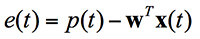
Let’s think in simple and intuitive terms about how this works. Take a look at Figure 3. Here we have a primary antenna P, and some auxiliary antennas A1, A2, and so on. A signal arriving from the direction shown impinges on antenna A2, and slightly later it arrives at A1, and later still it arrives at P. For the sake of argument, if the signal is a simple sine wave, you will then find that the output from each antenna is that same sine wave, but with a different phase shift depending on the spatial arrangement of the antennas.
Now, let’s consider what we call the “weights,” which are labeled as w1, w2 and so on. Each of the weights, in this case, is simply a phase shift that we can define. By careful choice of weights, we could choose to make each of the antenna outputs align perfectly in phase, and then, when we sum all the outputs together as shown, we end up with a bigger version of the input signal.
This is what we would like to achieve if the signal was a satellite. We “steer” maximum overall antenna gain towards that satellite. This is typically what is meant when we refer to “beamforming;” It means steering maximum antenna gain towards a satellite.
Conversely, we could also choose the weights to have the opposite effect: to minimize or completely cancel out the signal. This, of course, is what we would like to do if the signal was a jammer, and is referred to as “nulling” or “null-steering.”
Figure 3. Adaptive antenna basics.How do we determine what those weights should be? Well, this is where your standard theory in adaptive signal processing comes in. Let’s say the objective is to minimize the jamming power out of the antenna. We can write the output power of the adaptive antenna as:
Figure: Michael Jones
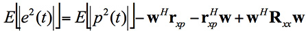
The average output power can be found by taking expectations:
Figure: Michael Jones
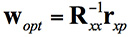
Taking the minimum and rearranging this leads to the well-known Wiener equation:
Figure: Michael Jones
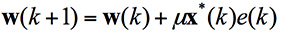
This Wiener equation is the one to remember. It says that the optimum weights can be found by taking the inverse of the data covariance matrix, and multiplying it by the vector of cross correlations between the primary and auxiliary antennas. As in any adaptive signal processing problem, a simple way to solve the Weiner equation and get the weights might be to use your favorite gradient descent algorithm, such as least mean squares (LMS):
Figure: Michael Jones
However, a solution using this approach does have its problems, for reasons beyond the scope of this article. The mathematics of beamforming are also bit more involved, so I’ll leave that out here.
Rather than the grossly simplified diagram used here, most decent CRPAs also use a more complex architecture based on space-time adaptive processing (STAP) or space-frequency adaptive processing (SFAP). This generally allows much higher levels of jammer cancellation against a wider range of threats.
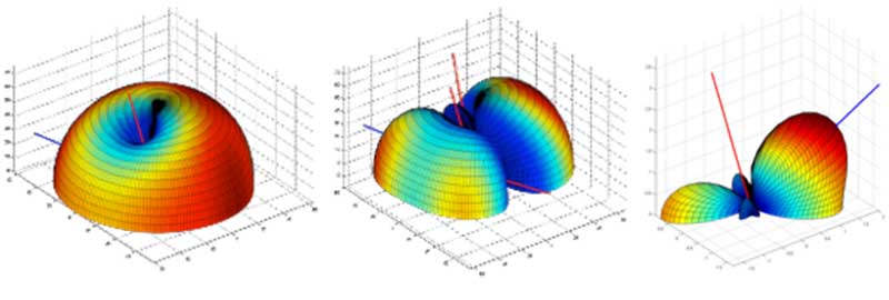
To finish off this whirlwind section on CRPA basics, let’s see what some example antenna gain patterns might look like. In the figures below, the blue line represents the direction of arrival of a GNSS satellite signal, whilst the red lines indicate the direction of arrival of a jammer. In the first diagram we have a single jamming signal: the antenna gain pattern is a nice hemisphere, as we would generally like, but there is a nice deep null in the direction of the jammer. Moving on to the next diagram, we can see the effect of having three simultaneous jammers on the same CRPA: again we have nice deep nulls in the direction of each jammer, but we are starting to lose more of the sky, and we may start to lose the odd satellite as a consequence. Finally, we have an example of beamforming on a single satellite, whilst nulling out a jamming source.
Again, it’s beyond the scope of this article, but the layout of the antenna elements plays an enormously important part in the performance and behavior of the CRPA.
Figure 4. Illustrative beam patterns of a CRPA antenna in the presence of jamming. (Figure: Michael Jones)Figure 4: Illustrative beam patterns of a CRPA antenna in the presence of jamming (Figure: Michael Jones)
Operational Anti-Jam Units
With some images courtesy of my friends at Raytheon, let’s look at a few examples of deployed military CRPA hardware over the years.
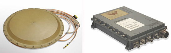
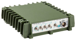
The GAS-1 system entered service in the U.S. in 1997, as a replacement for the earlier AE-1 (1990 to 1996). The CRPA is composed of two parts: the antenna array, which is a seven-element layout, and the antenna electronics as a separate box. The GAS-1 was incredibly successful and became the de facto standard anti-jam technology, fitted to air and sea platforms around the world. Even today, 20 years after its launch, it continues to be fitted to many platforms.
Figure 5. GAS-1 CRPA. (Photo: Raytheon)
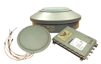
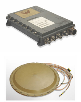
By the late 1990s and early 2000s, the Navigation Warfare (NAVWAR) program was in full swing, and the military was looking for enhanced protection against evolving jamming threats. The U.S. initiated a program called Advanced Digital Antenna Production (ADAP). The ADAP product, launched in 2006, was a direct form-fit replacement for the analog GAS-1 system, and introduced a number of advanced features. Most notably, the ADAP simultaneously protects both the L1 and L2 frequency bands, and utilizes STAP processing to achieve high levels of wideband jammer cancellation.
Figure 6. ADAP Digital CRPA. (Photo: Raytheon)
In parallel with the ADAP development, the Digital Antenna Control Unit (DACU) was different in a number of ways. Firstly, it was a true beamforming solution, allowing simultaneous antenna beams to be steered toward satellites, whilst simultaneously nulling out jammers.
Secondly, it was tightly integrated with the GPS receiver, with the GPS receiver hardware located in the same unit.
Thirdly, the DACU was able to perform a number of other advanced functions, such as direction-finding of interference sources. Interestingly, the DACU was used to help locate the source of the interference at the notorious Newark airport jamming incident in 2009.
By the mid-2000s, CRPA electronics were pretty mature and well-understood. The electronics had been miniaturized, and pretty much everything was put onto a single chip. But the physical size of the antennas persisted as a problem for some platforms requiring low size, weight and power (SWAP).
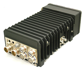
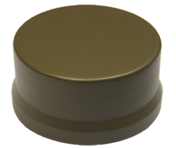
The Landshield, launched in 2014, was a step-change in CRPA technology. Not just because it was a small and fully self-contained unit (about the size of a hockey puck), but because it was the world’s first CRPA to include true anti-spoofing capability.
Figure 8. Landshield Advanced CRPA with Anti-Spoof Technology. (Photo: Raytheon)
Blurring the lines between military and civilian
Going back a few years, the military was heavily focused on CRPAs and anti-jam techniques in general. Military GPS receivers had been developed and deployed, and the question was how they could retrofit robustness to them. At the same time, the commercial world was heavily focused on mass-market GPS receivers — reducing cost, increasing performance — with little care about jamming.
If you’d talked to me five or six years ago, I would have said the military sector is 20 years ahead of the commercial sector in anti-jam technology, and the commercial sector is 20 years ahead of the military sector in receiver technology.
This assertion holds far less true these days; the lines of separation are much more blurred. The military is learning from the commercial world, embracing COTS, and developing new GNSS receivers. Conversely, civilian applications are now much more concerned with jamming, leading to the adoption of low-cost CRPAs in non-military applications.
The future of the CRPA
Where will CRPA technology go from here? We’ve already seen that the latest generation of CRPAs now performs anti-spoofing, as well as anti-jamming. But there is plenty more to see yet.
Although the core technology behind CRPAs is now mature, the trend for the future will be about “doing more with less.” CRPA technology will become more of a multi-function system. Military platforms need to cut down on the number of separate systems they install, and so CRPAs are likely to become multi-functional, performing situational awareness and signals intelligence.
As antenna technology progresses, we will likely see protected navigation solutions utilizing the same hardware as communication systems and radar systems, providing CESM and RESM functions, and being part of an integrated electronic warfare suite. And conformal antennas will see a resurgence of interest for complex and space-constrained platforms.
Narrowband IoT (NB‑IoT) is a new way of communicating with the “things” in Internet of Things that was standardized by 3GPP in June 2016.
The latest mobile broadband standard, NB-IoT is aimed at devices that need to communicate small amounts of data over long periods in hard-to-reach places. It connects devices through existing GSM and LTE spectrum networks.
NB-IoT uses the 3GPP-licensed network spectrum, which is secure and free from interference, and offers low power, long range, the ability to penetrate walls and metal barriers, and support for about 50,000 devices per single cellular cell.
“Narrowband IoT will be good for connecting devices in locations where the signal distance is in kilometers and for locations in basements and underground,” said Antenova CEO Colin Newman.
“It could be the enabler for some of the IoT applications that are emerging that are not suited to the established telecoms networks, where the data throughput is quite low and infrequent.
“We see these antennas being used for smart metering, agricultural technologies, building automation and smart-city applications with lighting, waste bins and parking spaces,” Newman said.
Digicom’s narrowband IoT GPS tracker has u-blox inside.
u-blox and Digicom. Chip-maker u-blox partnered with Digicom to develop its NB-IoT products, carrying out a series of innovative and successful field trials of the new NB-IoT technology.
Digicom offers solutions for industrial markets using NB-IoT, with a focus on connectivity solutions for smart cities, smart buildings, industry 4.0 in general and the automotive industry. Digicom platforms are designed for the protection of vehicles, people and pets, offer ultra-low-power consumption and several years of operation in battery mode.
Embedded in Digicom’s products are u-blox modules such as the SARA‑N2 NB-IoT.
CEVA Dragonfly. CEVA Inc. and Hong Kong Applied Science and Technology Research Institute Company Limited (ASTRI) introduced Dragonfly NB1, a comprehensive NB-IoT solution with excellent performance and power consumption. It is easily integrated into a system on chip (SoC).
GMV Add-On for GNSS. Also, CEVA and ASTRI teamed up with GMV to offer integrated GNSS for smart devices with location tracking of logistics, assets, wearables and more.
The GNSS IP is available as an add-on software that runs on the CEVA-X1 together with NB-IoT and leverages ASTRI’s GNSS RF IP embedded in the solution.
GMV’s software IP supports all four GNSS constellations: GPS, BeiDou, GLONASS and Galileo, and allows seamless switching between constellations when required or to run multiple constellations concurrently to improve resolution and offer global asset tracking.
Antenova Latona. Antenova has developed a new NB-IoT chip antenna in the company’s lamiiANT antenna family named Latona. The antenna measures 20 x 11 x 1.6 mm, and is built to a novel design that allows it to perform well within a device while being easy to integrate onto a small printed circuit board (PCB), as with all of Antenova’s embedded antennas.
Tallysman, manufacturer of economical high-performance GNSS antennas and related products, has introduced a through-hole mount dual-band plus L-band GNSS antenna, the TW3892.
The introduction of this antenna is a continuation of Tallysman’s expansion into broader band GNSS antennas.
The TW3892 antenna employs Tallysman’s Accutenna technology and is capable of receiving GPS L1/L2, GLONASS G1/G2, BeiDou B1, Galileo E1 plus L-band correction services (1213MHz to 1261MHz + 1525MHz to 1610MHz).
TW3892 (other radomes are available). Photo: Tallysman
This TW3892 is a precisely tuned antenna with a tight pre-filter to protect against intermodulation and saturation caused by high-level cellular 700 MHz and other signals.
The TW3892 antenna provides superior multipath signal rejection, a linear phase response, and a tight phase center variation (PCV) at an economical price point. It provides comparable or superior performance to higher priced dual-band GNSS antennas on the market.
The TW3892 is designed for precision agriculture, autonomous vehicles, navigation, real-time kinematic, precise point positioning and other applications where precision matters. The ability of the TW3892 to access L-Band correction services extends its utility to a wider range of applications.
The TW3892 is housed in a through-hole mount, weatherproof enclosure for permanent installations. For non-rooftop installations, L bracket or pipe mount (part numbers 23-0040-0, 23-0065-0 respectively) are available. A 100-mm ground plane is recommended for non-rooftop installations.
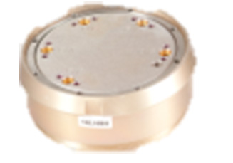
The mini choke ring antenna (right) with a traditionally sized antenna.
Harxon, manufacturer of high-precision antennas in China, has released a new patented mini choke ring antenna, the HX-CSX610A. Weighing less than 2 kg, the tiny antenna could be considered the next generation of reference antenna trends, Harxon said.
Harxon’s patent for the HX-CSX610A design includes its compact body, which offers flexible transportation and installation. Applications for the antenna include CORS stations, geodetic surveying and mapping, and other monitoring.
The HX-CSX610A is armed with excellent phase center symmetry and multipath suppression across all GNSS constellations, Harxon said, including GPS L1/L2/L5, GLONASS L1/L2, BDS B1/B2/B3, Galileo E1/E2/E5ab/E6 and L band.
For tracking performance, it can reach -0.5 dB at 20 degrees elevation.
An anti-jamming improvement over previous antenna is a method of combining the choke-ring structure with spatial filtering multipath signal suppression.
Hardware configurations meet IEC and GB standards. The antenna is water- and dust-proof.
Telit, a global enabler of the Internet of Things (IoT), has introduced advanced positioning modules in the SE868xx-Ax family featuring multi-constellation GNSS receivers with 9 square millimeter patch antennas.
Telit’s SE868Kx-Ax series offers high performance for space-constrained applications such as wearables, tracking, telematics and security. The new integrated antenna modules include advanced features that significantly increase RF sensitivity, allowing for a much simpler integration without external components.
The SE868K3-A/AL is a multi-constellation GNSS variant with flash memory and a GNSS core.
The SE868K7-A/AL is a GPS variant with ROM memory and a GPS core.
The new module variants are designed with the same, ultra-compact 11 square millimeter cavity PCB package as the other modules in the series, with the bonus of a second low noise amplifier (LNA) and surface acoustic wave (SAW) filter. Footprint compatible with other modules in the family, the SE868Kx-Ax series includes variants with multiple interfaces and a combination of features including:
Ultra-compact 11 x 11 mm “cavity” PCB package
Standard variant with integrated 9 millimeter by 9 millimeter by 4 millimeter SMT antenna
Low-profile variant with 9 millimeter by 9 millimeter by 2 millimeter antenna
Additional LNA and SAW filter
Real time clock (RTC) and temperature compensated crystal oscillator (TCXO)
Jamming rejection
Pin-to-pin compatibility with other modules in the series
Ephemeris file injection (A-GPS)
Satellite-Based Augmentation System (SBAS) compliant
With the different options available in the SE868Kx-Ax series, customers can design once and interchangeably mount the solution most appropriate for the environment, Telit said. This enables developers to select the right technology for their use case without having to redesign the entire application when it comes time to transition.
“The SE868Kx-Ax series is an exciting enhancement to our positioning product portfolio,” said Felix Marchal, EVP GNSS and short range, Telit. “Our commitment to excellence is reflected in the years of experience releasing breakthrough positioning modules and solutions. This latest release specifically addresses the integration challenges that IoT developers face today. Leveraging the low-profile and SMT mounting options that do not compromise the host PCB, developers can take advantage of the most important and advanced features available in positioning technology tangibly booting the efficiency of global design efforts, schedules and budgets.”
The Telit IoT Know How program assists customers to accelerate the deployment of cost-effective and future-proof solutions integrated with GNSS from idea to market, the company said.
The variants will be available in the second quarter of 2017. Telit is exhibiting them at Embedded World 2017, Nuremberg, Germany, March 14-16, located at hall 3, booth 3-518.


 With the introduction of this mount, customers can now upgrade existing GPS L1-only antennas to dual (L1/L2) and triple (L1/L2/L5) band GNSS antennas.