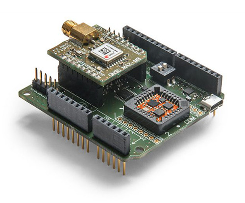
Xsens has expanded its MTi product portfolio with the introduction of the MTi-7, a miniature inertial navigation system (INS) module that uses input from an external GNSS receiver to provide an accurate, real-time position, velocity and orientation data stream.
The module has a compact 12 x 12-millimeter footprint, weighs less than 1 gram and consumes under 100 milliwatts, making it suitable for use in space- and power-constrained devices such as drones, as well as autonomous or remote-controlled mapping and imaging equipment.
Image: Xsens
Operating at output data rates up to 800 Hz, the MTi-7 achieves very low latency of 2 milliseconds, allowing for real-time operation of dynamic functions such as flight control and camera stabilization, the company said.
The module also offers a position and velocity output suitable for the navigation of autonomous ground vehicles in sectors such as smart farming and robotics.
The high performance of the MTi-7 is due to the advanced sensor fusion algorithms developed by Xsens to synchronize the inputs from the module’s onboard accelerometer, gyroscope and magnetometer with the signals from an external GNSS receiver or barometer.
The raw sensor signals are combined and processed at high speed in the MTi-7 module to produce a real-time data stream showing the device’s horizontal and vertical position, velocity, roll, pitch and yaw. This user-friendly data stream may be supplied to a host processor via a standard I2C, SPI or UART interface.
Based on the design of the successful MTi 1-series, the MTi-7 offers a straightforward upgrade path for current MTi-1 users on the same form factor. It is also able to provide heading, positioning and orientation accuracy more commonly found in much larger, heavier and higher power devices.
Image: Xsens
:We are seeing exploding demand for accurate control of autonomous or computer-guided equipment such as drones and smart farming ground vehicles,” said Hein Beute, director of product marketing at Xsens. “With its tiny footprint, light weight and low power consumption, the MTi-7 provides the industry’s best solution for any such application that is limited in terms of space or power but that needs a high degree of accuracy and precision in position and orientation data.’
The MTi-7 module is supported by an Arduino-compatible development kit (the MTi-7-DK), which provides access to the module’s I2C, SPI and UART interfaces via micro-USB connections.
Developers can configure the operation of the MTi-7 via the freely available Xsens MT Software Suite. The MT Software Suite includes a GUI for PCs operating on the Linux or Windows platforms, as well as a full Software Development Kit including example source codes and complete documentation.
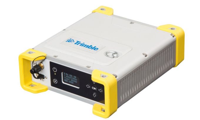
The MPS865 GNSS receiver is designed for marine positioning.
Trimble has debuted the MPS865 marine positioning system multi-frequency and multi-application GNSS receiver.
The Trimble MPS865 is a versatile, rugged and reliable GNSS positioning and heading solution for a wide variety of real-time and post-processing applications for marine survey and construction.
It features integrated communications options such as Wi-Fi, UHF radio, cellular modem for internet connectivity, Bluetooth and MSS satellite-based correction channels.
The patented GNSS-centric technology uses all available GNSS signals to deliver reliable positions in real time. The GNSS receiver provides for the connection of two GNSS antennas for precise heading.
With a modular form factor, the MPS865 is flexible and can be used as an integrated on-board rover receiver, a base station or a continuously operating reference station. According to Trimble, the built-in precise heading feature ensures the receiver is of minimal size, consumes less power and has less cabling, which are all benefits when on-board space it at a premium.
The MPS865 adds new features to improve usability in a congested marine construction site – multi constellations, cellular connectivity and beacon support. The multi-constellation option maintains productivity in marine sites or when antennas or satellites are partly obstructed.
At many sites, the receiver can use the free-to-air beacon support. When coupled with GA830 antennas, the MPS865 will receive the free-to-air beacon signals to deliver sub-meter accurate horizontal positioning in many parts of the world. It always delivers precise heading even when no GNSS corrections are received.
The marine receiver also has cellular, making it easier to use Internet Base Station Service (IBSS) and VRS corrections over the internet as well as communicate with the receiver via the internet and SMS messages. The receiver also can be used as a data access point on the vessel to download design files or for immediate remote support.
The MPS865’s design enables a broad range of mounting capabilities and built-in communication options. Features include an internal removable battery, internal memory and optional accessory kits for specific applications.
The receiver is also compatible with a variety of software solutions including the new Trimble Marine Construction software.
The weatherproof, high-impact-resistant moulded aluminium housing protects it in extreme marine conditions or base-station applications.
“With the addition of the MPS865 receiver to our portfolio, Trimble has introduced a new generation of rugged, compact and feature-rich GNSS, a solution the marine industry has been needing for some time,” said Scott Crozier, general manager of Trimble’s Civil Engineering & Construction Division. “This highly flexible and capable receiver can be combined with our marine construction software providing contractors with a market-leading solution for any marine survey or construction application.”
Tersus GNSS is now offering its David real-time kinematic (RTK) GNSS receiver with seven new base/rover kits.
Tersus GNSS is a provider of centimeter-accuracy GNSS RTK solutions. The Tersus David GNSS receiver with its components create an affordable solution delivering high-precision signal reception, integrated in a small, and lightweight package.
The David GNSS receiver supports GPS L1/L2, GLONASS G1/G2 and BeiDou B1/B2. With David, surveyors users can take full advantages of common platforms such as smartphones, tablets or traditional handheld modules to collect data.
Coupled with an external antenna, the Survey App and post-processing software, the David GNSS receiver is a low-cost solution for all survey applications, including real-time RTK positioning and data collection for PPK.
Four (4) GB on board an embedded multimedia card (eMMC) makes it easy to save data for post processing. The compact, IP67-rated enclosure and versatile accessories alleviate most inconveniences encountered in field work.
“The launch of David GNSS Receiver marks a major step forward for Tersus as well as for surveying professionals,” said Xiaohua Wen, founder and CEO of Tersus. “The David is a cost-efficient and palm-sized GNSS receiver. Tersus is constantly working to make each surveying task easier and more productive by providing high-quality GNSS RTK surveying equipment. Our focus is on enabling surveying professionals make data collection more convenient, post (data collection) processing more accurate, and better equipping them to do surveying in the field.”
By Tommaso Panicciari, Mohamed Ali Soliman and Grégory Moura
All images provided by the authors
A real-time system combining a simulator and a GNSS propagation model reproduces an authentic multipath environment. The propagation model relies on a 3D-model reconstruction of the urban environment, which generates a multipath signature strictly dependent on the location of the receiver’s antenna. This yields important results for a moving vehicle, which may be affected by very different multipath conditions depending on trajectory and location.
Positioning and navigation can be degraded in urban environments by multipath, and the error can increase considerably if not properly compensated. In situations where the line-of-sight (LOS) is obscured by surrounded buildings, the receiver may still be able to navigate by using the non-line-of-sight (NLOS) signal, which originates from single or multiple reflections/diffractions of the GNSS signal.
The use of 3D models has been one of the preferred solutions to recreate the multipath environment as seen by a GNSS device. This solution brings the capability to generate a multipath signature that is representative of the position of the antenna in a specific time and space. However, this solution comes with a certain degree of complexity. In fact, an accurate 3D model is required to simulate the obscuration of the GNSS signal, and a good propagation model is needed to generate phenomena like reflection and diffraction.
Figure 1. Example of propagated signal simulation. (Image: Tommaso Panicciari, Mohamed Ali Soliman and Grégory Moura))\
3D models have become more accurate and widely available and are mainly used to predict the satellite availability in specific locations, for example in evaluating the signal availability in urban canyon, and for both reflection and diffraction. Other uses of 3D models are as an aiding tool to assist navigation, sometimes together with an INS solution.
In this article, we present a novel real-time system capable of simulating realistic multipath in different environments. The system can simulate multiple GNSS constellations and is comprised of a GNSS simulator interfaced to a propagation model. The system can create a whole range of signals, effects, error models and trajectories in a real-time closed loop. The propagation model controls the simulation of multipath from the interaction of the GNSS signal with the 3D scene and objects. This article describes a novel real-time system for the simulation of realistic multipath in different environments and compares simulated and field-test data. The comparison is based on signal availability, horizontal error, carrier-to-noise (C/N0), pseudorange and Doppler residuals.
RAY-TRACING WITH 3D MODELING
The model simulates the propagation of GNSS signals in constrained environments, considering obscurations and multipath. It uses a proprietary ray-tracing kernel (based on bounding volume hierarchy techniques using processing unit [GPU] resources) coupled with geometrical optics and uniform theory of diffraction to compute the interaction between the signal and the local environment. The computation uses as main input a synthetic environment (that is, geometrical and physical modeling of a real or realistic environment) to assess the impact of obscurations related to signal availability issues and multipath (the cause of fading effects and performance problems).
The objective of ray-tracing is to find all the possible paths from the observer to the source of the signal considering a limited number of interactions per emitted rays. A ray-tracer (or ray-tracing algorithm) uses a primary grid to cast primary rays. Then, it iteratively computes the possible interactions between these rays and the virtual scene (often defined using triangles). If those interactions exist (if they comply with the law of physics) and if the number of interactions to reach the emitter is below the maximum number of interactions set by the user, then a ray (or multipath) is created. This is a deterministic method that can be used to calculate the obscuration due to the local environment (and therefore detect the signal availability) and the geometrical characteristic of the computed path. Combined with physics modeling, path attributes such as received power, delay, Doppler, and phase are also provided.
The main characteristics of ray-tracing techniques to model GNSS propagation are:
All the signals arriving at the receiver can be model-based on the virtual environment.
As it is a deterministic method, the more realistic the environment modeling, the more compliant with reality the results. Moreover, the simulation results are repeatable.
The specular multipath can be displayed in 3D, and the attributes (for example, receiver power, phase, polarization, Doppler, geometry of the ray) are known. For example, this is relevant when the effect and signature of the environment on the propagation signal need to be studied and understood.
Nonetheless, ray-tracing techniques must account for three major difficulties:
They are time-consuming algorithms. Indeed, depending on the complexity of the scene (defined in terms of the number of triangles), a combinatorial problem to find the possible multipaths reaching the receiver makes the ray-tracer very resource-demanding. That is the reason why the most difficult task to achieve during the coding of a real-time ray-tracing algorithm is to develop acceleration techniques to quicken the computation process. Several solutions exist to either improve the intersection determination (for instance, based on spatial hierarchies such as bounding volume hierarchy [BVH] techniques), or to decrease the number of cast rays (often based on adaptive sampling techniques), or even to replace rays with beams or cones. Moreover, it is possible today to use the resources of graphic boards to accelerate the computation. Indeed, as ray-tracing can be coded by a large number of primary functions that can be treated simultaneously, it can be easily ported into GPU.
Their accuracy depends on the resolution of the primary grid. Details and therefore rays may be missed if the 3D scene is made of small details. This issue is called aliasing. Aliasing artefacts are raised for instance in parts of the scene with abrupt changes (such as edges) or in complex areas with lots of constituent objects. Solutions (or antialiasing techniques) exist to overcome this issue such as adaptive or stochastic samplings.
When it is combined with geometrical optics, these algorithms only compute the specular rays. Even if some techniques exist to model the scattering signals, only physical optics can render the global signal with high fidelity.
MULTIPATH SIMULATION SYSTEM
The proposed system can model two of the main propagation issues encountered in urban environments, such as obscuration (which leads to limitations in signal availability) and multipath (which generates interference that causes fading of the signal and positioning errors). To model realistically such a complex phenomenon, the system uses a GPU ray-tracing algorithm combined with geometrical optics and uniform theory of diffractions. The ray-tracing algorithm relies on 3D-model reconstructions of the urban environment. The computed obscuration and multipath effects are then used to generate signal corrections (in terms of power, delay and Doppler variation) to be used in the GNSS simulator, which generates the carrier, code and navigation messages for different GNSS constellations into a single RF output. Some of the advantages of this system is its ability to run in real time, and to visually show all the reflections/diffractions of the GNSS signals that cause multipath interference.
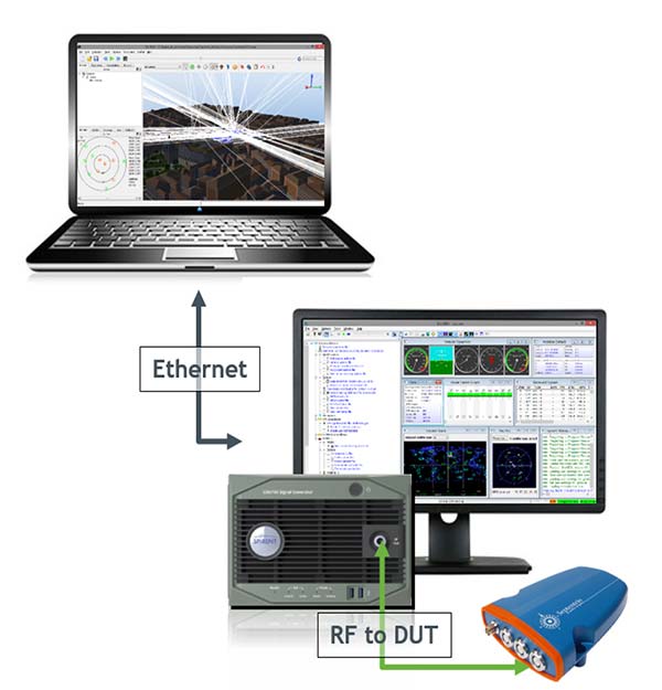
Figure 2 shows the diagram of the system set up in conductive mode. The system includes a SE-NAV PC controller, simulator software suite controller, GNSS simulator and device under test (DUT). A different mode is also available called over the air (OTA). This mode uses an anechoic chamber and a set of antennas distributed uniformly to generate the RF signal including the multipath. The DUT can then be placed at the center of the chamber and will be able to receive LOS and NLOS signals from different angles of arrival.
Figure 2. System diagram that shows propagation simulator controller (top), the GNSS simulator (bottom) and the device under test connected to the RF output of the simulator. (Image: Tommaso Panicciari, Mohamed Ali Soliman and Grégory Moura)
The GNSS simulator software suite is used to generate and control the generation of the satellite signals (including multipath) at RF, whilst the propagation simulator is used to calculate the propagation information (delay, Doppler and attenuation) of the reflected signals through a 3D urban model. The propagation software is interfaced with GNSS simulator software by means of a package of remote-control facilities that greatly enhances the flexibility of the propagation simulator. Those commands can be sent and received through the transmission control protocol/use datagram protocol (TCP/UDP) with different data streaming rates (10 Hz was used for this article).
It is also important to point out that the propagation simulator computes all the possible multipath signal generated by the 3D model given the position of the satellites and receiver. However, the physical limitation of the number of channels in the simulator causes the rejection of some rays. This rejection or filtering process can be done according to power (used in this article) or delay.
EXPERIMENT SET-UP
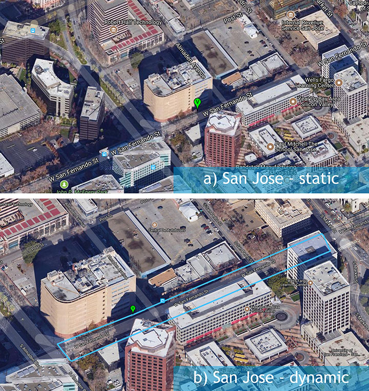
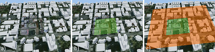
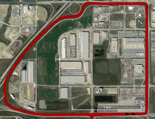
A set of different field-test campaigns where carried out in August 2016. Each campaign aimed to evaluate the ability of the system to assess the performances of a GNSS receiver using simulated signals in urban environments. Figure 3 shows the trajectory (blue line) used for the experiment in an urban environment — San Jose, California — with a static (a) and dynamic (b) scenario.
Figure 3. A set of three measurement campaigns where carried out during Aug. 9–10, 2016: a) urban environment with static antenna; b) urban environment with dynamic antenna. (Image: Tommaso Panicciari, Mohamed Ali Soliman and Grégory Moura)
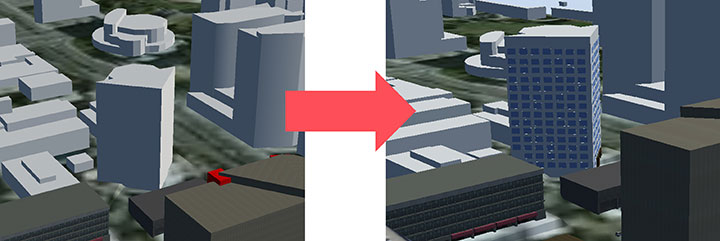
Figure 4 shows the 3D scene used to replicate the San Jose urban environment. The buildings in close proximity of the antenna (green area in Figure 4b) contain details like material, 3D facade and windows. In contrast, the buildings far from the antenna were only corrected for height, and the material was modeled as concrete only.
Figure 4. The San Jose model contained most of the details around the receiver antenna (b), with only height corrected for buildings far from the antenna (c). (Image: Tommaso Panicciari, Mohamed Ali Soliman and Grégory Moura)
An exception was made for one building in San Jose because its complex architecture was believed to contribute to more reflected rays than would a more simplistic box (concrete) model (Figure 5).
Figure 5. Improvement (right) in one San Jose building because its complex architecture was believed to generate more reflections than the more simplistic box model (left). (Image: Tommaso Panicciari, Mohamed Ali Soliman and Grégory Moura)
EXPERIMENT RESULTS
A direct comparison of C/N0 power, pseudorange residual, and Doppler residual was performed between the field test and simulation.
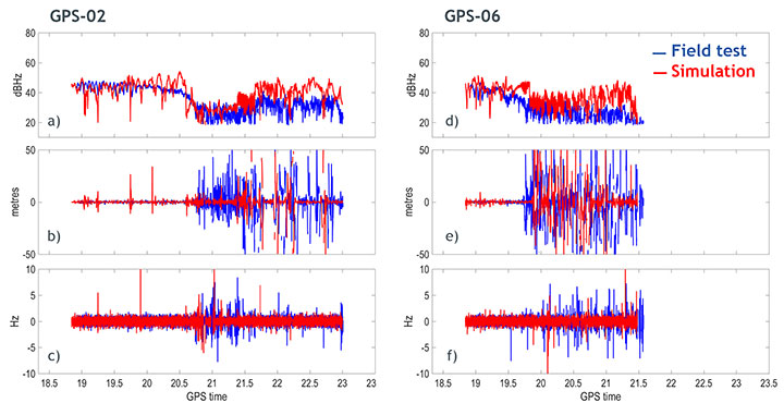
San Jose Static Results. Figure 6 shows the results obtained from the San Jose static scenario for satellites PRN02 and PRN06: C/N0 ratio, pseudorange residual and Doppler residual for field test (blue line) and simulation (red line). Although the simulation sometimes creates deeper fading than in the field test, a first comparison indicates a good correlation of simulated data with field-test data.
Figure 6. Carrier-to-noise ratio (top), pseudorange residual (middle) and Doppler residual (bottom) for PRN 02 (left column) and PRN 06 (right column). (Image: Tommaso Panicciari, Mohamed Ali Soliman and Grégory Moura)
The signature of the multipath caused by this urban environment is visibly captured in the simulation. More interestingly, the pseudorange residuals and, to a lesser extent, Doppler residuals also indicate that the model is replicating the dynamics of the multipath environment in close correlation with the field test.
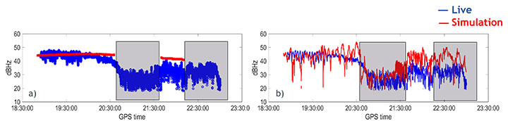
Figure 7 shows the C/N0 obtained from the field data (blue), and simulated data (red) with only obscuration (a) and with obscuration and multipath (b) for the static scenario.
It can be noticed that the receiver can still track PRN02 without the LOS, therefore, relying on just the NLOS signal. This can be clearly seen in Figure 7a where a sudden drop in power is associated to an obscuration of the same satellite (based on our 3D urban model).
Figure 7b shows the C/N0 obtained from the simulation (red line) when both obscuration and multipath were enabled. In this case the receiver could track the satellite even in the case of only NLOS as in the field test.
Figure 7. Carrier-to-noise ratio for satellite PRN02 with only obscuration (a) and with multipath (b). (Image: Tommaso Panicciari, Mohamed Ali Soliman and Grégory Moura)
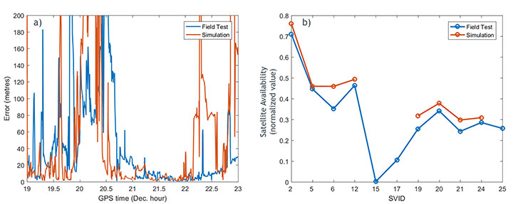
The positioning error for the San Jose static scenario is shown in Figure 8a. The simulation and field-test data have a comparable error. The error is relatively big at the beginning of the simulation and decreases after time 20.6. At the time 22.3, a moderate increase in the positioning error is visible in the field data until the end of the test. The simulation also shows a similar trend in this last part of the test, but tends to generate a higher positioning error.
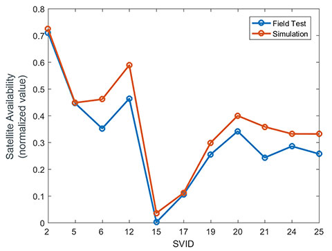
The satellite availability is shown in Figure 8b for both simulated (red) and field test (blue). The availability of the satellites generated with simulated data is in close relationship with the field data. However, some satellites could not be tracked in the simulation.
Figure 8. a) positioning error for field-test (blue) and simulation (red); b) satellite availability for field data (blue) and simulation (red). (Image: Tommaso Panicciari, Mohamed Ali Soliman and Grégory Moura)
The importance of the accuracy of the 3D scene is evident in this example. In fact, we noticed that one of the buildings that was simulated as a simple concrete box was more complex in the real environment. Therefore, we applied some modifications to scene, as in Figure 9.
Figure 9. 3D scene improvement. (Image: Tommaso Panicciari, Mohamed Ali Soliman and Grégory Moura)
After those changes, a general improvement in the results was visible, but most importantly, the missing satellites could finally be tracked by the receiver (Figure 10).
Figure 10. Satellite availability for field data (blue) and simulation after scene improvement. (Image: Tommaso Panicciari, Mohamed Ali Soliman and Grégory Moura)
SAN JOSE DYNAMIC TEST RESULTS
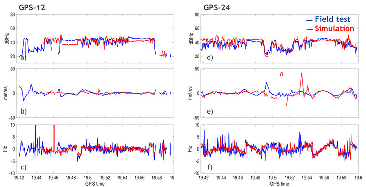
Similar results were obtained with the dynamic test in San Jose. Figure 11 shows the results obtained for satellites PRN12 and PRN24. The walking trajectory included two points where the antenna was stopped because of a traffic light. Those points correspond to a relatively flat C/N0 that can be clearly seen in the field test and simulation data for both PRNs. When, instead, the antenna was moving, a higher variation in the C/N0 is noticeable in both simulation and field test.
Figure 11. Carrier-to-noise ratio (top), pseudorange residual (middle), and doppler residual (bottom) for PRN 12 (left column) and PRN 24 (right column). (Image: Tommaso Panicciari, Mohamed Ali Soliman and Grégory Moura)
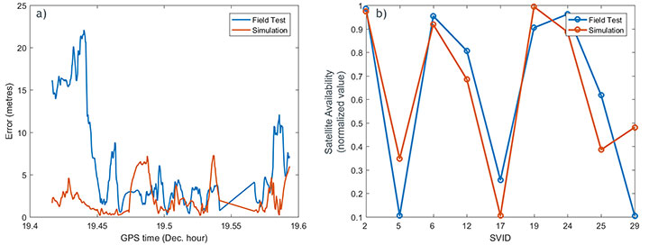
Figure 12a illustrates the positioning error obtained from simulated (red) and field test (blue). The first part of the simulation produced an error smaller than the one obtained from field data. However, from the time 19.48, a good agreement can be seen. The satellite availability is also shown in Figure 12b. This last result was obtained with the improved model described in Figure 9.
Figure 12. (a) Positioning error for field-test (blue) and simulation (red); (b) satellite availability for field data (blue) and simulation (red) after scene improvement. (Image: Tommaso Panicciari, Mohamed Ali Soliman and Grégory Moura)
CONCLUSIONS AND FUTURE WORK
A new real-time system for multipath simulation is designed to generate realistic multipath that depends on time, position and type of urban environment. The 3D scene is used to calculate the multipath (reflection and diffraction) caused by the buildings and objects around the antenna.
Some first results demonstrated that realistic multipath can be generated by simulating reflections and diffractions even with a simple 3D model. However, the inclusion of finer details in the model can improve the simulation and make it even closer to reality.
As always, simulation interest is a tradeoff between reliability in all conditions and efforts to adapt (that is, to specify) a generic and simple model. The added value of our model consists in its simplicity and its good compliance with field data.
Ray-tracing techniques coupled with geometrical optics and uniform theory of diffraction are efficient and simple methods to simulate the propagation of GNSS signals in complex urban environments. Their efficacy is demonstrated by a good agreement between simulation and field measurements. Some discrepancies still exist and are due to the limitations of such a model:
The accuracy of the model is never perfect and, as ray-tracing is a deterministic method, the returned results strongly depend on the quality of the input data used to generate the model.
Geometrical optics is a simple (but efficient) method. Only specular rays are modeled, thus the system won’t be able to generate all the signals coming from other phenomena such as scattering. Another limitation is given by the hardware. In fact, the number of simulated multipath depends on the number of available channels in the simulator.
The simulation parameters try to mimic the field conditions. However, the simulated trajectory is approximated, and other factors like pedestrian motion, vegetation (isolated trees or forest) and traffic may contribute to reduce some of the discrepancies that can be observed between simulation and field
All of these limitations can explain the differences between simulated and measured data. Currently, the impact of vegetation (forest and/or isolated trees) models, pedestrian motion and traffic on the multipath signal can also be simulated and their performances are under evaluation.
ACKNOWLEDGMENTS
We thank Colin Ford and Ajay Vemuru from Spirent Communications and Antoine Boudet, Yann Dupuy, Arnold Duquesne and Paul Pitot from OKTAL Synthetic Environment.
MANUFACTURERS
The system described in this article consists of a Spirent GNSS simulator equipped with a SimGEN software suite and the SE-NAV simulator developed by OKTAL Synthetic Environment. SE-NAV is interfaced with SimGEN via the SimREMOTE protocol, a real-time control and motion API.
Tommaso Panicciari obtained a Ph.D. in telecommunications from the University of Bath (UK). He is a software/project engineer at Spirent Communications where his main activity focuses on spoofing and multipath simulation.
Mohamed Ali Soliman is completing a master’s degree in telecommunications with business at University College London. He is a product manager at Spirent Communications, managing multiple products including the multipath simulation offering.
Grégory Moura graduated from the French Institute of Aeronautics and Space with an M.S. in cosmology from Université de Toulouse. He manages the GNSS activities of the French company OKTAL Synthetic Environment.
Hemisphere GNSS has introduced the Vector V1000 GNSS receiver for precision marine applications. The V1000 provides high-accuracy heading, position, pitch, roll and heave data.
The company made the announcement at the Oceanology International conference being held this week in London, U.K.
The V1000 supports multi-frequency GPS, GLONASS, BeiDou, Galileo, QZSS and IRNSS (with future firmware upgrade and activation) for simultaneous satellite tracking. The receiver is powered by Hemisphere’s Athena real-time kinematic (RTK) engine and is Atlas L-band capable.
The new V1000 is designed for professional marine applications, such as hydrographic and bathymetric surveys, dredging, oil platform positioning, buoys and other applications that demand the highest level 3D positioning accuracies. Based on Hemisphere’s Eclipse Vector technology, the V1000 uses the most accurate differential corrections including RTK and Atlas L-band.
The V1000 is Hemisphere’s flagship receiver, with an integrated display, that can be conveniently installed near the operator. The two antennas can be installed at user-specified separation, providing valuable flexibility in terms of install locations and desired heading accuracy.
The V1000 has heading accuracy of better than 0.01 degree when using a 10-meter antenna separation. With CAN, serial, Bluetooth, Wi-Fi and Ethernet support and flexible installation, the all-new rugged enclosure gives the V1000 the advantage of working reliably in harsh environments, the company said.
Geneq has launched the SXblue Premier GNSS receiver, which is available in a submetric version (GNSS) or centimetric version (real-time kinematic, RTK).
The new SXblue Premier GNSS receiver is equipped with the Pacific Crest Maxwell 6 Trimble technology with BD910 (GNSS version) and BD930 (RTK version) OEM boards, delivering 220 channels to acquire and track GNSS signals from all constellations in view. It makes effective use of GPS, GLONASS, Galileo, BeiDou, QZSS and SBAS signals for outstanding highly precise positioning.
The SXblue Premier is small and light weight, and rugged for field work. It is equipped with dual mode for Bluetooth V2.1 and Bluetooth V4.0, ensuring the unit’s wireless communication with any Android or Windows terminal. With its two models, the user will have large efficiency and flexibility on the field either with SBAS corrections or RTK reference networks.
In addition, SXblue Premier can be configured for Wi-Fi hotspots, allowing users to connect and access a web management platform. It also can be used as a data link, providing a quick connection to the internet to receive corrections from reference station (CORS) networks so that it can process RTK measurements.
With its internal memory using an 8-GB solid state disk, SXblue Premier provides enough storage space for field data collection or raw data recording for a high data sampling rate.
Multiple compatible software programs — including FieldGenius, Carlson, Collector for ArcGIS — will meet the users’ diverse need, making SXblue Premier more powerful and flexible.
NovAtel has integrated its high-precision positioning engine and correction services with automotive-grade multi-frequency GNSS chipsets from STMicroelectronics: specifically, the Teseo APP (Automotive Precise Positioning) and Teseo V.
The integration demonstrates possibilities for vehicle localization solutions. NovAtel is part of Hexagon’s Positioning Intelligence Division.
STMicroelectronics’s Teseo APP and Teseo V provide multi-frequency GNSS data for PPP (precise point positioning) and RTK (real-time kinematic) for accurate positioning capabilities.
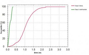
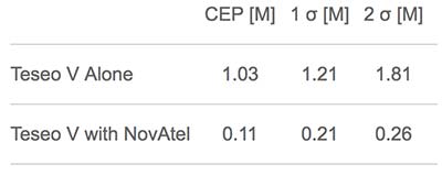
The Teseo V SBAS and Teseo V NovAtel PPP tests took place in a light urban environment. (Image: NovAtel)
NovAtel’s positioning engine combines the GNSS measurements from these chipsets with inertial measurement unit (IMU) data and Hexagon PPP correction services on the demonstration platform to deliver centimeter-level PPP positioning solutions in real time.
“Working closely with STMicroelectronics using their Teseo APP chipset allowed us to innovate and speed up the development of our assured positioning solution tailored specifically for safe positioning of autonomous vehicles,” said Jonathan Auld, VP Engineering and Safety Critical Systems from NovAtel.
NovAtel’s positioning engine architecture enables a flexible integration with different GNSS receiver chipsets, IMUs and processor environments, providing automotive manufacturers with additional flexibility when it comes to selecting components and subsystems of advanced driver assistance systems (ADAS) and autonomous driving solutions.
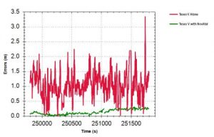
Test results: Horizontal position errors. Teseo V alone is shown in red, Teseo V + NovAtel in green. Test results: Horizontal cumulative error distribution. Teseo V alone is shown in red, Teseo V + NovAtel in green. (Chart: NovAtel)
Test results: Horizontal cumulative error distribution. Teseo V alone is shown in red, Teseo V + NovAtel in green. (Chart: NovAtel)
The positioning engine is being developed to ASIL-B standards according to ISO26262 and will include a proprietary GNSS integrity solution to ensure safe positioning within defined protection limits that are tailored to the customer’s application requirements.
“NovAtel’s choice of the automotive-quality ASIL-capable Teseo APP to integrate with their GNSS positioning engine is enabling them to develop a world-class safety-critical positioning offering to the automotive industry,” said Antonio Radaelli, Director, Infotainment Business Unit, STMicroelectronics.
NovAtel technology continues to be an integral part of the connected and autonomous car ecosystems, including academic research, industry development and real-life applications. The company’s automotive positioning solution includes automotive GNSS antenna technology, GNSS/INS positioning engine, and global correction services.
Assisting safer autonomous driving, STMicroelectronics has introduced a multi-frequency GNSS receiver chipset suitable for safety-critical automotive applications and high-accuracy positioning at the decimeter and centimeter-level for precise point positioning (PPP) and real-time kinematic (RTK) applications.
Traditional in-car navigation systems help drivers reach their destinations using receivers and commercial satellite services that allow positioning accurate to within a few meters.
With increasing use of autonomous systems such as lane-departure warning (LDW), adaptive cruise control (ACC), valet parking and auto-pilot, greater accuracy is needed to ensure safety and reliability, in combination with proximity sensors such as cameras, radar, lidar and others, to monitor the driving environment automatically. Fully self-driving vehicles of the future will also demand high-accuracy positioning.
By tracking satellites of all GNSS constellations simultaneously on at least two of the frequencies used by each system, ST’s automotive-quality Teseo APP (automotive precise positioning) receiver provides high-quality raw GNSS data for PPP and RTK algorithms, which allows accurate positioning and rapid convergence time worldwide.
In addition to its high accuracy, the receiver monitors the integrity of the satellite data to alert the system if accuracy is degraded for any reason. This permits Tier-1 manufacturers to certify safety-critical systems in accordance with the automotive industry functional-safety standard, ISO 26262, up to the highest Automotive Safety Integrity Level (ASIL).
Teseo APP also integrates a secure microcontroller for secure system boot and data-output authentication to keep sensitive data safe from attack.
Launched alongside Teseo APP, ST’s Teseo V chip provides equivalent multi-frequency precise positioning in a simplified device for non-safety-critical applications where integrity assurance is not required.
“High-accuracy satellite positioning makes autonomous driving safer, smoother, and more reliable,” said Antonio Radaelli, director, Infotainment Business Unit, STMicroelectronics. “Our newest Teseo APP GNSS chip combines extreme accuracy and precision with industry-unique integrity assurance for use in safety-critical applications.”
Teseo APP eliminates errors by tracking all available GNSS signals in multiple frequency bands, such as the GPS and GLONASS, Galielo, BeiDou, QZSS, and IRNSS L1, L2, and L5 frequency bands, and the Galileo E6 signal that contains PPP correction data to allow worldwide decimeter-level accuracy.
Other techniques for enhancing accuracy have included differential systems reliant on a combination of ground base-station signals as well as satellite signals, or techniques such as RTK, which generally require a denser reference station network.
The new Teseo chips make high-accuracy affordable for autonomous driving through a combination of tracking up to three constellations simultaneously over two frequency domains. These multi-frequency combinations bring reliable GNSS ionospheric and multipath modeling in most environments, allowing accurate positioning with faster convergence time for automotive applications, where timing is critical.
ST is now supplying product samples to lead customers who are developing autonomous-driving systems expected to appear first in high-end vehicles launched in 2020/2021.
Visitors to Mobile World Congress 2018 in Barcelona, Feb. 26 to March 1, can see Teseo APP at the ST booth, Hall 7, Stand 7A61.
Two methods of spoofer detection, the identification and sourcing of false GNSS signals, have been released by Javad GNSS, using features available for all of its OEM GNSS boards.
Spoofer detection and alarm. This feature then identifies and isolates the spoofer signal, ignores it, and provides a position solution using only valid satellite signals.
Determination of the direction from which the spoofing signals emanate. This can aid in tracking down the actual spoofing source.
Spoofer Detection
With 864 channels and roughly 130,000 quick-acquisition correlators, the Javad GNSS Triumph chip can assign more than one channel to each GNSS satellite, in order to find all the signals that are transmitted with that satellite’s PRN code. If the chip detects more than one reasonable and consistent correlation peak for any PRN code, it concludes that spoofing is present and can the proceed to identify the spoofed signals.
In this case, it uses the position solution provided by all other clean signals (L1, L2, L5, and so on, from all GNSS constellations — GPS, GLONASS, Galileo, Beidou, and mroe) to identify the spoofer signal and use the real satellite measurement. If all GNSS signals are spoofed or jammed, then the system issues an alarm, directing the user to ignore GNSS and use other sensors in an integrated system.
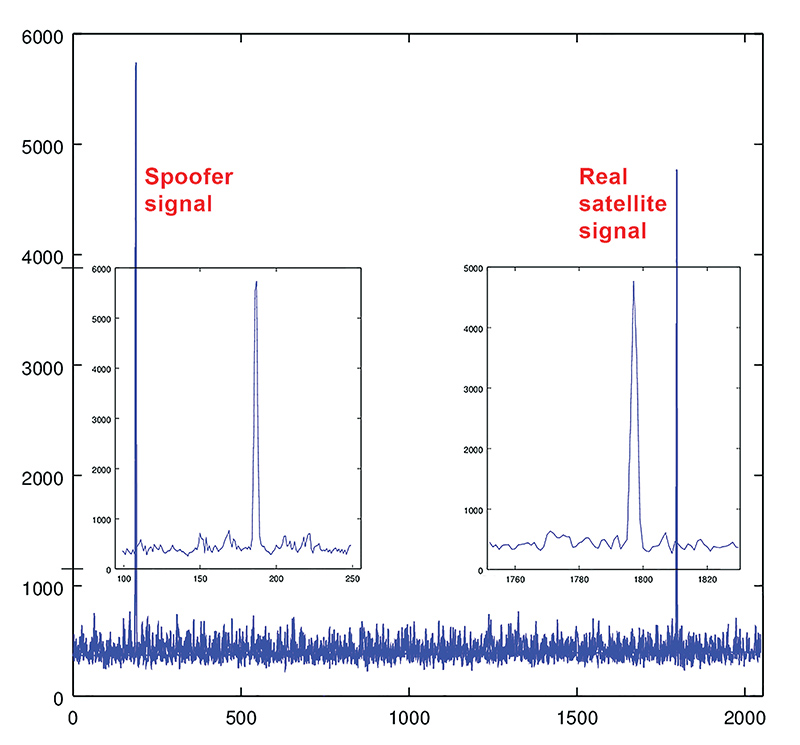
Satellite and Spoofer Peaks
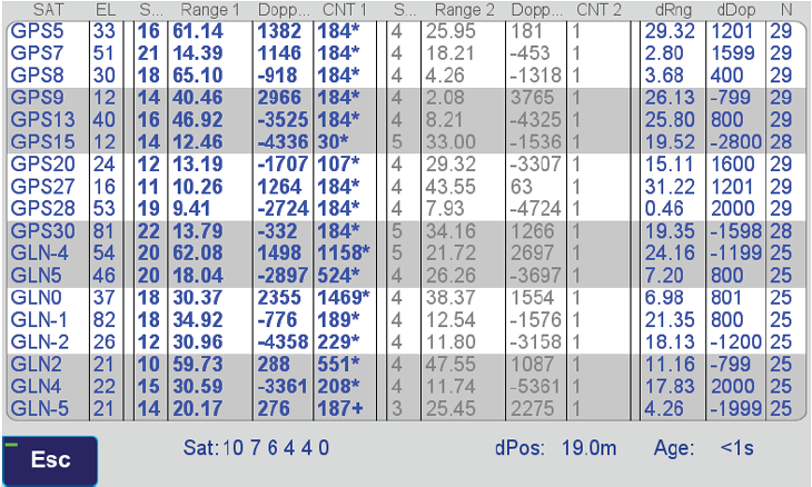
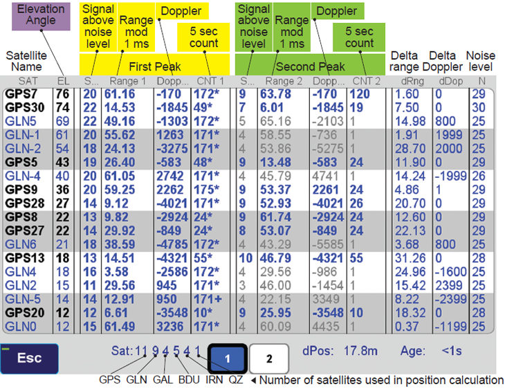
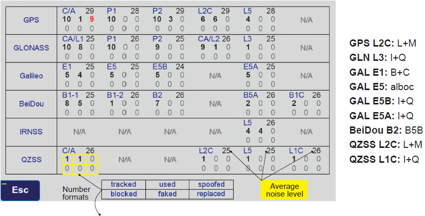
The figure below shows an example of a spoofer signal and a real satellite signal received at a GNSS receiver. These screenshots are from a real spoofer in a large city. The bold numbers are for the detected peaks. The gray numbers represent highest noise, not a consistent peak. A “*” symbol next to the CNT numbers indicate that signal is used in position calculation. Each CNT count represent about 5 seconds of continuous peak tracking.
The first screenshot shows no spoofing is present. The second shows that all GPS satellites are being spoofed.
No spoofer. Only one reasonable peak for each satellite. (Table: Javad GNSS)Table: Javad GNSS
In the above screenshot all GPS satellites have two peaks and all are spoofed. We were able to distinguish the spoofer signal and use the real satellite signals in correct position calculation as indicated by the ”*” next to the CNT numbers.
GNSS Overall View
The following screenshot shows the status of all GNSS signals. The format and the signal definitions are explained below.
Table: Javad GNSS
Tracked: Tracked by the tracking channels and has one valid peak only.
Used: Used in position calculation.
Spoofed: Has two peaks. Good peak is isolated, if existed.
Blocked: Blocked by buildings or by jamming. If jammed, shows higher noise level.
Faked: Satellite should not be visible, or such PRN does not exist.
Replaced: Real signal is jammed and a spoofed signal put on top of it. Because of jammer, it shows higher noise level.
Q: What is the biggest challenge facing designers of multi-constellation GNSS receivers today?
Javad Ashjaee, founder of Javad GNSS: The biggest challenge now is spoofing.
Some years ago the issue was jamming —the hot issue of LightSquared — that would hurt GNSS. To solve that problem we created the J-Shield and showed that J-Shield technology could protect against LightSquared and similar signals. We manufactured dozens of units that were successfully tested by several independent laboratories.
Now GNSS faces the spoofing issue. Reports of Black Sea spoofing and other examples show the urgency of paying attention to this problem. When a spoofer is successful, both position and time are spoofed.
A Nov. 3 CNN video report on this subject gives an example of how little people know about spoofing and about the work that has been done on this subject. The report claims that GNSS technology companies have not done much or spent money on this subject. Obviously the reporter doesn’t know what we have done, as I will report here.
I’ll review the spoofing methods and how we counter them.
Source: Javad GNSS
Spoofers use three methods: One simple way is to broadcast GNSS-like signals that provide the wrong ranging information which, when used, creates wrong position and time solutions. Most probably this is the method that Prof. Todd Humphreys used to spoof the GNSS receiver on the $80 million yacht [“GNSS Lies, GNSS Truth,” November 2014 GPS World.] This method fools the GNSS receiver into ignoring the correlation peak of the real satellite signal and using the correlation peak of the spoofer signal. To deal with this type of spoofer we take advantage of the 864 tracking channels and over 130,000 fast acquisition channels of our TRIUMPH chip. We assign more than one channel to each satellite signal and we track all their peaks: The real peak and the spoofer’s peaks. Then in Step 1, below, we exclude all signals with more than one correlation peak.
Method Two is broadcasting spoofed signals for satellites that are below the horizon in the spoofed area or for satellites that do not exist. In this case only one correlation peak exists. Our equipment and OEM boards can download valid and certified almanac data from our website to know the status of satellites and their visibility ahead of their mission. Almanac data can be used for several weeks.
Method Three is to cover the signal of a visible satellite with noise and on top of the noise add the spoofer signal with more power. We recognize such spoofers by their unreasonable signal power and the background noise.
In the first counter-spoofing step we ignore these signals:
Those with more than one peak;
Those that according to our almanac should not be visible;
Those with unreasonably high or inconsistent signal-to-noise ratio (SNR);
Systems whose satellites all have similar SNR.
Satellites that do not generate complete multi-frequency signals (spoofers usually generate only C/A code).
After removing all questionable signals, we use the remaining signals to compute our approximate position. We need at least 4 signals from the many available signals of GPS L1, L2P, L2C, L5, GLONASS L1, L2, L3, and the many signals of BeiDou, QZSS and IRNSS.
In the second step we validate all questionable signals against the approximate position that we have calculated and keep only those that pass our validation. We then re-compute the more precise position using all good signals. We consistently throw away the spoofer correlation peak and use the real satellite signal.
If all signals of all satellites are spoofed, then we warn the user to ignore the GNSS signals and use some other sensors (like compass and gyro) to get out of the spoofed area. A spoofer that can spoof all signals of all satellites will be very expensive to build and deploy.
In a very difficult situation, the user can enter their approximate position to quickly understand if spoofers exist, and then identify them.
All the counter-spoofing methods that I have discussed here are the subject of patents for which we have applied.
Since currently most of spoofers spoof the L1 C/A code, we can simply initially ignore the C/A signals to compute the initial approximate position and use it to identify the spoofed signals.
It is vital that in areas that spoofing danger exists, users employ OEM boards that provide more satellite systems and more signals, rather than using a simple GPS C/A code, for example.
Finally I would like to challenge Prof. Todd Humphreys [professor and director, Radionavigation Laboratory, University of Texas-Austin] to spoof any of our receivers that have this anti-spoofing option. We offer this as an option on all of our OEM boards.
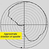
An experiment in an anechoic chamber with a JAVAD GNSS TRIUMPH-LS shows the approximate orientation of the spoofer (at 283° azimuth.)
Javad GNSS advises that with its equipment it is possible, when a spoofer is detected in the area, to identify the direction from which the spoofing signals are coming.
Hold the receiver antenna horizontally and rotate it slowly (one rotation in 30 seconds) to determine the angle at which satellite energies become minimum.
The spoofer’s direction lies behind the null point of the antenna reception pattern.
An experiment in an anechoic chamber with a Javad GNSS Triumph-LS shows the approximate orientation of the spoofer (at 283 degree azimuth.)
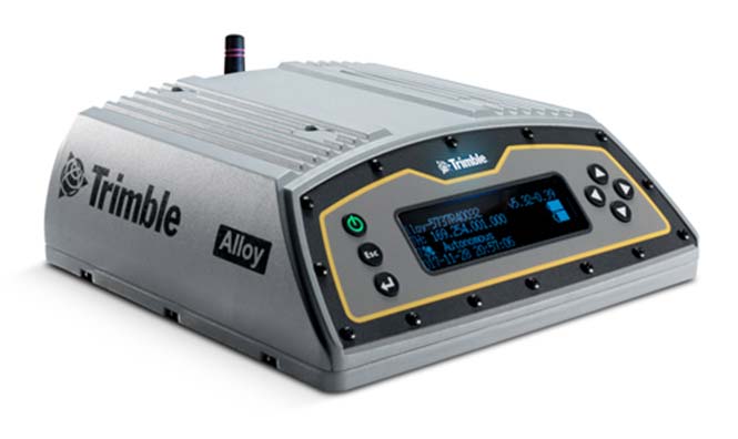
Trimble has introduced its next-generation GNSS reference receiver for real-time network (RTN) applications: the Trimble Alloy GNSS reference receiver.
With 672 channels, the continuously operating reference station (CORS) receiver provides users and operators with access to multiple constellations and signals, supplying robust and reliable reference data.
With an IP68 rating for protection against dust and moisture, the Trimble Alloy performs even in the most rugged environments to meet the demands of professionals from the earth science, surveying, construction, mapping and agricultural industries.
Delivering high-accuracy GNSS data to improve RTN performance and reliability, the Trimble Alloy GNSS receiver allows RTN owners and operators to:
Track and log all current and planned GNSS. Powered by the new Trimble Maxwell 7 GNSS dual chipsets, Trimble Alloy tracks and processes all of today’s current GNSS signals at data rates up to 100Hz, and is designed to be ready for planned signals and systems. The next generation receiver provides 672 channels for unrivaled GNSS constellation tracking including: GPS, GLONASS, BeiDou, Galileo, QZSS, IRNSS as well as the full range of SBAS.
Deliver absolute position monitoring. Leveraging Trimble RTX precise point positioning technology, the Trimble Alloy receiver is able to derive its position at centimeter-level accuracy in real-time. Combined with Trimble’s advanced Sentry monitoring technology, the receiver will automatically notify the operator of any status change including positional changes. The technology ensures users are receiving the most accurate correction data.
Realize new levels of user convenience. An all new intelligent receiver design brings an unprecedented level of usability to GNSS reference stations with the Trimble Alloy reference receiver. Featuring a tilted four-line OLED screen, Trimble Alloy displays key information without the need for scrolling through multiple menus. Dual hot swappable batteries, coupled with multiple power inputs, give users flexible installation options. Wi-Fi connectivity, multiple serial ports and remote access options allow users to configure the device easily, no matter how or where it’s installed.
“Alloy provides a solution to address a variety of installation challenges faced by RTN owners and operators today,” said Mark Richter, marketing director of Trimble’s Advanced Positioning Division. “The receiver can track all satellite signals at the highest possible data rate while being easy to use, access and configure. All of these features make the receiver a compelling investment for owner/operators who are looking to modernize their networks or single station configurations. Trimble Alloy will carry them far into the future.”
The Trimble Alloy GNSS reference station receiver is expected to be available in most of the world through Trimble’s Distribution Channel during the first quarter of 2018. For Asia and Latin America, the receiver is expected to be available in the second quarter of 2018.