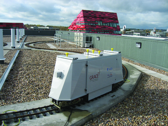
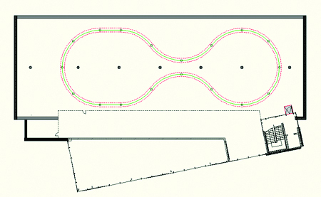
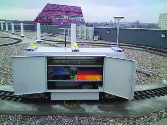
One-hundred-twenty meters of test track, designed for repeatable dynamic position testing, run along the roof of the new Nottingham Geospatial Building at the University of Nottingham, UK. The figure-eight track provides an optimal controlled environment with test equipment aboard a remote-controlled, multi-sensor 7¼-inch gauge locomotive platform with a top speed of 7 kilometers per hour, a dedicated power supply, and five antenna mounts. Simulation of the track using Spirent GSS8000 hardware (GPS and Galileo) provides additional planning and testing capacity.
The combination of these tools creates the ideal environment for our new project: augmentation of GNSS systems with ground-based Locata positioning technology. This pseudolite-like system, described in the March issue of GPS World, works in a GNSS-like fashion, using code and carrier phase. The major advantage, apart from utilization of the licensee-free 2.4 GHz frequency band, is the precise time synchronization of the network to the nanosecond level.
The proposed integration addresses Locata’s weak vertical coordinates (due to relative coplanarity of transceivers) and GNSS’s requirement for a clear view of the sky and location-specific weak geometric distribution of the satellites. Prior research and analysis suggests considerable improvement in 3D positioning accuracy when combining ground-based positioning devices (pseudolites) with GNSS, but the current project pushes the research forward by attempting to create on-the-fly ambiguity resolution.
Combination of hardware and software simulation has provided an initial assessment of the proposed integration, optimization of equipment location, and test of the mathematical model to be used. Practical tests, using the roof lab on top of the NGB, will further verify the method and allow comparisons between the predicted and real-life results. This will aid the assessment of noise, multipath, and in-bound interference. The test design minimizes the tropospheric effect, while track flexibility and repeatability offer the possibility of implementing and simulating obstructions and areas of GNSS outage. This will provide a full assessment of the mathematical model and the integrated system’s capacity.
This project offers new opportunities in civil engineering, specifically monitoring and machine control. GPS is currently widely used for those applications, with Locata also proven successful. The integrated solution can provide not only enhanced positioning capacity but lower the required number of visible GNSS satellites, and offer improved integrity and quality control, ultimately increasing the safety of life.
The intended utilization is for positioning in dense urban areas and essential structures (airports, seaports, factory sites, bridges) where sky visibility or correct satellite distribution cannot be guaranteed.
The track is available for other projects. Funded by East Midlands Development Agency, hosted by the Institute of Engineering Surveying and Space Geodesy, the Centre for Geospatial Science, and the GNSS Research and Applications Centre of Excellence (GRACE).
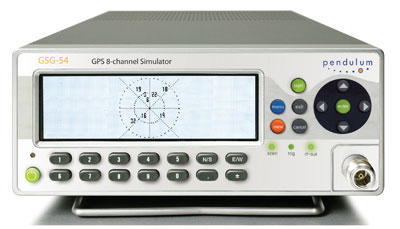
Spectracom’s new 8-channel GPS constellation simulator, the Pendulum GSG-54, provides a wide-range of capabilities for in-line production testing of devices integrating GPS receivers due to its ease-of-operation and fast test cycles. Its versatility also supports engineering organizations’ efforts for integrating GPS receivers into devices under development.
The Pendulum GSG-54 simulates the satellite signals detected by a GPS receiver. It comes in a bench-top chassis that is compact and portable. It offers built-in standards-based test scenarios that can be initiated or modified on the fly from the intuitive front panel interface, and offers a variety of connectivity options to control and reconfigure test parameters.
The GSG-54 GPS constellation simulator builds on the features available from Spectracom’s GSG-L1 single-channel GPS signal generator that offers simple but fast assembly verification for functions such as antenna connectivity, receiver operation, or satellite signal identification. The GSG-54 provides for many more test cases due to its ability to simulate eight different satellite signals to test position accuracy, sensitivity to loss of satellite signals, timing accuracy, and dynamic range. It can simulate movements and user trajectories, multi-path scenarios and various other atmospheric conditions.
Spectracom’s new 8-channel GPS constellation simulator, the Pendulum GSG-54, provides a wide-range of capabilities for in-line production testing of devices integrating GPS receivers due to its ease-of-operation and fast test cycles, according to the company. Its versatility also supports engineering organizations’ efforts for integrating GPS receivers into devices under development.
As more and more electronic devices integrate GPS receivers, manufacturers require instrumentation to fully test the GPS capabilities of each device on the manufacturing floor. According to Staffan Johansson, Spectracom product manager, “We understand the need for high-throughput manufacturing testing of GPS receivers. A multi-channel GPS simulator must be easy to use, yet powerful enough to confirm each device’s performance under a variety of real-world conditions.”
The Pendulum GSG-54 simulates the satellite signals detected by a GPS receiver. It comes in a bench-top chassis that is compact and portable. It offers built-in standards-based test scenarios that can be initiated or modified on the fly from the intuitive front panel interface, and offers a variety of connectivity options to control and reconfigure test parameters, Spectracom said.
The GSG-54 GPS constellation simulator builds on the features available from Spectracom’s GSG-L1 single-channel GPS signal generator that offers simple but fast assembly verification for functions such as antenna connectivity, receiver operation, or satellite signal identification. The GSG-54 provides for many more test cases due to its ability to simulate eight different satellite signals to test position accuracy, sensitivity to loss of satellite signals, timing accuracy, and dynamic range. It can simulate movements and user trajectories, multi-path scenarios and various other atmospheric conditions.
“Like our other products, the GSG-54 offers the lowest cost of ownership for manufacturers and development engineers by providing complete testing of multi-channel GPS performance with high throughput and ease-of-use without unnecessary complexity or expense,” said Lisa Withers, president and CEO of Spectracom.
Aeroflex has introduced the GPSG-1000, a portable GPS and Galileo positional simulator. The GPSG-1000 is lightweight and configurable. It fills a gap in the market by providing a low-cost 12-channel test set that creates three-dimensional simulations, Aeroflex said.
With the advent of GPS signal modernization, many GPS simulators on the market today are now obsolete, according to the company, which is based in Witchita, Kansas. The GPSG-1000 supports civil and military avionics field and bench maintenance technicians, production test technicians, and system integrators with a modern simulator for L1, C/A code and L1C, L2C, L5 GPS modernization signals, as well as new Galileo E1, E5, E6 services. It can be configured with single channel, 6-channel, or 12-channel simulation. Typical tests include acquisition sensitivity, tracking sensitivity, time-to-first-fix for cold/warm/hot starts, time-to-second-fix, positional accuracy, RAIM failure tolerance, and subsystem stimulation for 3D flight execution.
The Aeroflex GPSG-1000 uses modular technology for RF and baseband signal generation to produce highly accurate and repeatable test results. Unlike bench top simulators, Aeroflex’s approach also allows the test system to be upgraded at low cost.
Features include:
Simulation of GPS L1C, L2C, L5 signals, supporting the modernization of signals used by the latest designs of GPS receivers.
Simulation of Galileo E1, E5, E6 signals to support unencrypted services.
SBAS, WAAS/EGNOS L1, L5, for automatic SBAS simulation.
Built-in GPS C/A code receiver for automatic GPS almanac download.
Waypoint navigation, a 3D-navigation scheme that allows airport-to-airport flight plan simulation.
Programmable satellite parameters allow specific tests to be conducted to determine receiver behaviour under degraded or invalid signal conditions.
Dynamic satellite signal simulation for real-world constellation signal conditions.
The GPSG-1000 Portable Positional Simulator is available in single channel, 6-channel, and 12-channel configurations. The GPSG-1000 is available in 16 weeks upon receipt of order.
Navigation and positioning test system supplier Spirent Communications this week introduced a software suite for the STR4500 GPS simulator, enabling users to generate their own test cases based on motion data that fits their specific requirements, the company said.
Launched in 2001, the STR4500 provides pre-defined test cases for the testing of GPS receivers and systems to be replayed using a PC-based controller with RF signal generator hardware. Typical users of the STR4500 are involved with the selection, integration, verification or production test of GPS L1 C/A code systems, according to Spirent.
The new SimPLEX45 software enables unique test cases to be generated, saved and run directly by the user. SimPLEX45 also enables user-defined motion-data to be used with atmospheric models and the environment around a vehicle, the company said.
“This new software will enable our customers to drive a route and, using logged NMEA data, generate a trajectory for a test case,” stated John Pottle, marketing director for Spirent’s Wireless and Positioning Division. “The user also will be able to define the antenna pattern, atmospheric effect and obscuration due to buildings or other obstructions. We’ve built this capability into the STR4500 to provide our customers with reduced development times via improved tailoring of test scenarios to fit their specific needs.”
The SimPLEX45 is available with new systems or as an easy to install upgrade to existing STR4500 users, Spirent said.
To initially acquire the GPS signals, a receiver also would have to search quickly through the much larger range of possible Doppler shifts and code delays than those experienced by a terrestrial receiver.
By William Bamford, Luke Winternitz and Curtis Hay
INNOVATION INSIGHTS by Richard Langley
GPS RECEIVERS have been used in space to position and navigate satellites and rockets for more than 20 years. They have also been used to supply accurate time to satellite payloads, to determine the attitude of satellites, and to profile the Earth’s atmosphere. And GPS can be used to position groups of satellites flying in formation to provide high-resolution ground images as well as small-scale spatial variations in atmospheric properties and gravity.
Receivers in low Earth orbit have virtually the same view of the GPS satellite constellation as receivers on the ground. But satellites orbiting at geostationary altitudes and higher have a severely limited view of the main beams of the GPS satellites. The main beams are either directed away from these high-altitude satellites or they are blocked to a large extent by the Earth.
Typically, not even four satellites can be seen by a conventional receiver. However, by using the much weaker signals emitted by the GPS satellite antenna side lobes, a receiver may be able track a sufficient number of satellites to position and navigate itself. To initially acquire the GPS signals, a receiver also would have to search quickly through the much larger range of possible Doppler shifts and code delays than those experienced by a terrestrial receiver.
In this month’s column, William Bamford, Luke Winternitz, and Curtis Hay discuss the architecture of a receiver with these needed capabilities — a receiver specially designed to function in high Earth orbit. They also describe a series of tests performed with a GPS signal simulator to validate the performance of the receiver here on the ground — well before it debuts in orbit.
“Innovation” is a regular column featuring discussions about recent advances in GPS technology and its applications as well as the fundamentals of GPS positioning. The column is coordinated by Richard Langley of the Department of Geodesy and Geomatics Engineering at the University of New Brunswick, who appreciates receiving your comments and topic suggestions. To contact him, see the “Columnists” section in this issue.
Calculating a spacecraft’s precise location at high orbits — 22,000 miles (35,400 kilometers) and beyond — is an important and challenging problem. New and exciting opportunities become possible if satellites are able to autonomously determine their own orbits.
First, the repetitive task of periodically collecting range measurements from terrestrial antennas to high-altitude spacecraft becomes less important — this lessens competition for control facilities and saves money by reducing operational costs. Also, autonomous navigation at high orbital altitudes introduces the possibility of autonomous station-keeping. For example, if a geostationary satellite begins to drift outside of its designated slot, it can make orbit adjustments without requiring commands from the ground. Finally, precise onboard orbit determination opens the door to satellites flying in formation — an emerging concept for many scientific space applications.
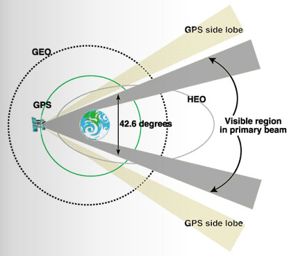
Realizing these benefits is not a trivial task. While the navigation signals broadcast by GPS satellites are well suited for orbit and attitude determination at lower altitudes, acquiring and using these signals at geostationary (GEO) and highly elliptical orbits (HEOs) is much more difficult. This situation is illustrated in FIGURE 1.
Figure 1. GPS signal reception at GEO and HEO orbital altitudes.
The light blue trace shows the GPS orbit at approximately 12,550 miles (20,200 kilometers) altitude. GPS satellites were designed to provide navigation signals to terrestrial users — because of this, the antenna array points directly toward the Earth. GEO and HEO orbits, however, are well above the operational GPS constellation, making signal reception at these altitudes more challenging. The nominal beamwidth of a Block II/IIA GPS satellite antenna array is approximately 42.6 degrees. At GEO and HEO altitudes, the Earth blocks most of these primary beam transmissions, leaving only a narrow region of nominal signal visibility near the limb of the Earth.This region is highlighted in gray.
If GPS receivers at GEO and HEO orbits were designed to use these higher power signals only, precise orbit determination would not be practical. Fortunately, the GPS satellite antenna array also produces side-lobe signals at much lower power levels. The National Aeronautics and Space Administration (NASA) has designed and tested the Navigator, a new GPS receiver that can acquire and track these weaker signals, dramatically increasing signal visibility at these altitudes.
While using much weaker signals is a fundamental requirement for a high orbital altitude GPS receiver, it is certainly not the only challenge. Other unique characteristics of this application must also be considered. For example, position dilution of precision (PDOP) figures are much higher at GEO and HEO altitudes because visible GPS satellites are concentrated in a much smaller region with respect to the spacecraft antenna. These poor PDOP values contribute considerable error to the point-position solutions calculated by the spacecraft GPS receiver.
Extreme Conditions. Finally, spacecraft GPS receivers must be designed to withstand a variety of extreme environmental conditions. Variations in acceleration between launch and booster separation are extreme. Temperature gradients in the space environment are also severe. Furthermore, radiation effects are a major concern — spaceborne GPS receivers should be designed with radiation-hardened parts to minimize damage caused by continuous exposure to low-energy radiation as well as damage and operational upsets from high-energy particles. Perhaps most importantly, we typically cannot repair or modify a spaceborne GPS receiver after launch. Great care must be taken to ensure all performance characteristics are analyzed before liftoff.
Motivation
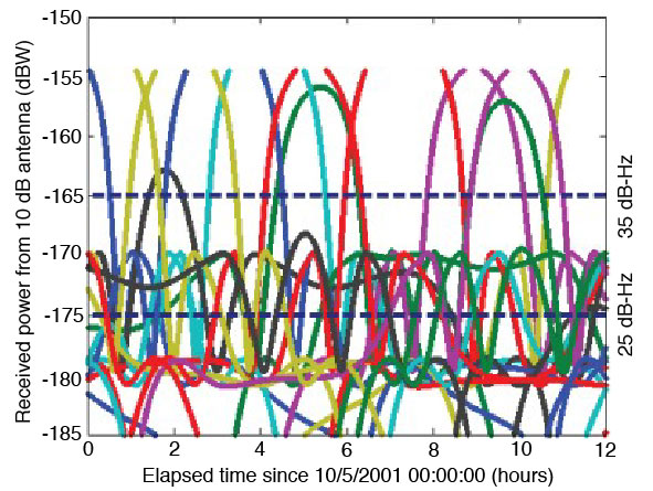
As mentioned earlier, for a GPS receiver to autonomously navigate at altitudes above the GPS constellation, its acquisition algorithm must be sensitive enough to pick up signals far below that of the standard space receiver. This concept is illustrated in FIGURE 2. The colored traces represent individual GPS satellite signals. The topmost dotted line represents the typical threshold of traditional receivers. It is evident that such a receiver would only be able to track a couple of the strong, main-lobe signals at any given time, and would have outages that can span several hours.
The lower dashed line represents the design sensitivity of the Navigator receiver. The 10 dB reduction allows Navigator to acquire and track the much weaker side-lobe signals. These side lobes augment the main lobes when available, and almost completely eliminate any GPS signal outages. This improved sensitivity is made possible by the specialized acquisition engine built into Navigator’s hardware.
Figure 2. Simulated received power at GEO orbital altitude.
Acquisition Engine
Signal acquisition is the first, and possibly most difficult, step in the GPS signal processing procedure. The acquisition task requires a search across a three-dimensional parameter space that spans the unknown time delay, Doppler shift, and the GPS satellite pseudorandom noise codes. In space applications, this search space can be extremely large, unless knowledge of the receiver’s position, velocity, current time, and the location of the desired GPS satellite are available beforehand.
Serial Search. The standard approach to this problem is to partition the unknown Doppler-delay space into a sufficiently fine grid and perform a brute force search over all possible grid points. Traditional receivers use a handful of tracking correlators to serially perform this search. Without sufficient information up front, this process can take 10–20 minutes in a low Earth orbit (LEO), or even terrestrial applications, and much longer in high-altitude space applications. This delay is due to the exceptionally large search space the receiver must hunt through and the inefficiency of serial search techniques.
Acquisition speed is relevant to the weak signal GPS problem, because acquiring weak signals requires the processing of long data records. As it turns out, using serial search methods (without prior knowledge) for weak signal acquisition results in prohibitively long acquisition times.
Many newer receivers have added specialized fast-acquisition capability. Some employ a large array of parallel correlators; others use a 32- to 128-point fast Fourier transform (FFT) method to efficiently resolve the frequency dimension. These methods can significantly reduce acquisition time. Another use of the FFT in GPS acquisition can be seen in FFT-correlator-based block-processing methods, which offer dramatically increased acquisition performance by searching the entire time-delay dimension at once. These methods are popular in software receivers, but because of their complexity, are not generally used in hardware receivers.
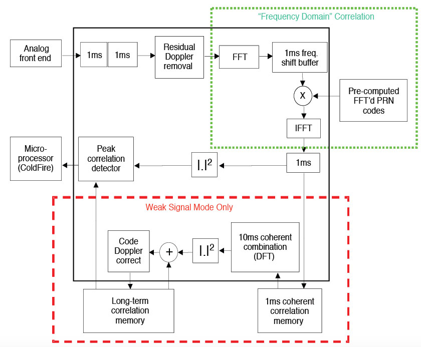
Exceptional Navigator. One exception is the Navigator receiver. It uses a highly specialized hardware acquisition engine designed around an FFT correlator. This engine can be thought of as more than 300,000 correlators working in parallel to search the entire Doppler-delay space for any given satellite. The module operates in two distinct modes: strong signal mode and weak signal mode. Strong signal mode processes a 1 millisecond data record and can acquire all signals above –160 dBW in just a few seconds. Weak signal mode has the ability to process arbitrarily long data records to acquire signals down to and below –175 dBW. At this level, 0.3 seconds of data are sufficient to reliably acquire a signal.
Additionally, because the strong, main-lobe, signals do not require the same sensitivity as the side-lobe signals, Navigator can vary the length of the data records, adjusting its sensitivity on the fly. Using essentially standard phase-lock-loop/delay-lock-loop tracking methods, Navigator is able to track signals down to approximately –175 dBW. When this tracking loop is combined with the acquisition engine, the result is the desired 10 dB sensitivity improvement over traditional receivers. FIGURE 3 illustrates Navigator’s acquisition engine.
Powered by this design, Navigator is able to rapidly acquire all GPS satellites in view, even with no prior information. In low Earth orbit, Navigator typically acquires all in-view satellites within one second, and has a position solution as soon as it has finished decoding the ephemeris from the incoming signal. In a GEO orbit, acquisition time is still typically under a minute.
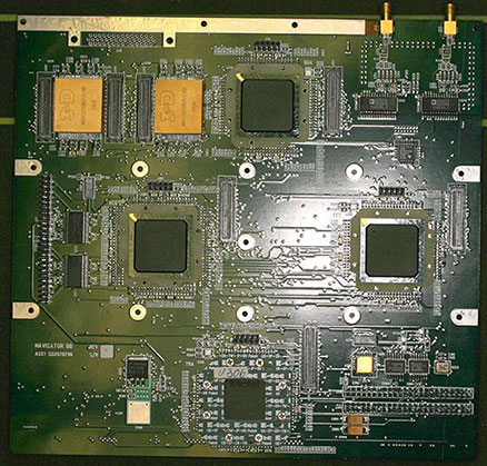
Figure 3. Navigator signal acquisition engine.Navigator breadboard.GPS constellation simulator.
Navigator Hardware
Outside this unique acquisition module, Navigator employs the traditional receiver architecture: a bank of hardware tracking correlators attached to an embedded microprocessor. Navigator’s GPS signal-processing hardware, including both the tracking correlators and the acquisition module, is implemented in radiation-hardened field programmable gate arrays (FPGAs). The use of FPGAs, rather than an application-specific integrated circuit, allows for rapid customization for the unique requirements of upcoming missions. For example, when the L2 civil signal is implemented in Navigator, it will only require an FPGA code change, not a board redesign.
The current Navigator breadboard—which, during operation, is mounted to a NASA-developed CPU card—is shown in the accompanying photo. The flight version employs a single card design and, as of the writing of this article, is in the board-layout phase. Flight-ready cards will be delivered in October 2006.
Integrated Navigation Filter
Even with its acquisition engine and increased sensitivity, Navigator isn’t always able to acquire the four satellites needed for a point solution at GEO altitudes and above. To overcome this, the GPS Enhanced Onboard Navigation System (GEONS) has been integrated into the receiver software. GEONS is a powerful extended Kalman filter with a small package size, ideal for flight-software integration. This filter makes use of its internal orbital dynamics model in conjunction with incoming measurements to generate a smooth solution, even if fewer than four GPS satellites are in view.
The GEONS filter combines its high-fidelity orbital dynamics model with the incoming measurements to produce a smoother solution than the standard GPS point solution. Also, GEONS is able to generate state estimates with any number of visible satellites, and can provide state estimation even during complete GPS coverage outages.
Hardware Test Setup
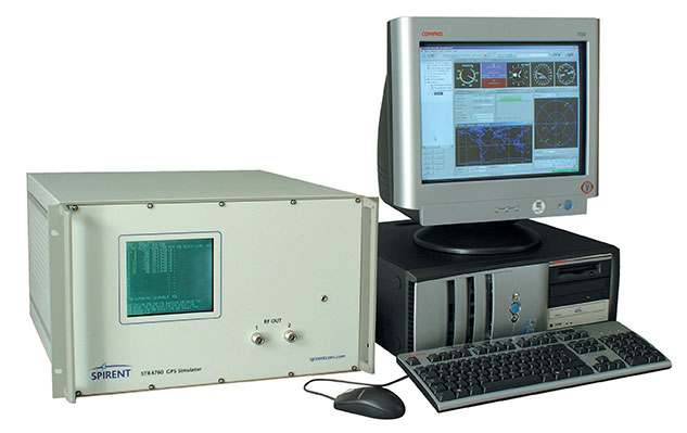
We used an external, high-fidelity orbit propagator to generate a two-day GEO trajectory, which we then used as input for the Spirent STR4760 GPS simulator. This equipment, shown in the accompanying photo, combines the receiver’s true state with its current knowledge of the simulated GPS constellation to generate the appropriate radio frequency (RF) signals as they would appear to the receiver’s antenna. Since there is no physical antenna, the Spirent SimGEN software package provides the capability to model one.
The Navigator receiver begins from a cold start, with no advance knowledge of its position, the position of the GPS satellites, or the current time. Despite this lack of information, Navigator typically acquires its first satellites within a minute, and often has its first position solution within a few minutes, depending on the number of GPS satellites in view. Once a position solution has been generated, the receiver initializes the GEONS navigation filter and provides it with measurements on a regular, user-defined basis. The Navigator point solution is output through a high-speed data acquisition card, and the GEONS state estimates, covariance, and measurement residuals are exported through a serial connection for use in data analysis and post-processing.
We configured the GPS simulator to model the receiving antenna as a hemispherical antenna with a 135-degree field-of-view and 4 dB of received gain, though this antenna would not be optimal for the GEO case. Assuming a nadir-pointing antenna, all GPS signals are received within a 40-degree angle with respect to the bore sight. Furthermore, no signals arrive from between 0 and 23 degrees elevation angle because the Earth obstructs this range. An optimal GEO antenna (possibly a high-gain array) would push all of the gain into the feasible elevation angles for signal reception, which would greatly improve signal visibility for Navigator (a traditional receiver would still not see the side lobes). Nonetheless, the following results provide an important baseline and demonstrate that a high-gain antenna, which would increase size and cost of the receiver, may not be necessary with Navigator. The GPS satellite transmitter gain patterns were set to model the Block II/IIA L1 reference gain pattern.
Simulation Results
To validate the receiver designs, we ran several tests using the configuration described above. The following section describes the results from a subset of these tests.
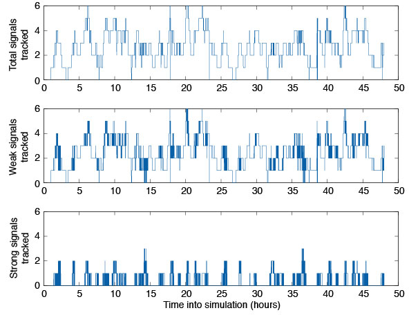
Tracked Satellites. The top plot of FIGURE 4 illustrates the total number of satellites tracked by the Navigator receiver during a two-day run with the hemispherical antenna. On average, Navigator tracked between three and four satellites over the simulation period, but at times as many as six and as few as zero were tracked. The middle pane depicts the number of weak signals tracked—signals with received carrier-to-noise-density ratio of 30 dB-Hz or less. The bottom panel shows how many satellites a typical space receiver would pick up. It is evident that Navigator can track two to three times as many satellites at GEO as a typical receiver, but that most of these signals are weak.
Figure 4. Number of satellites tracked in GEO simulation.
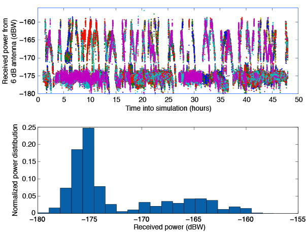
Acquisition Thresholds. The received power of the signals tracked with the hemispherical antenna is plotted in the top half of FIGURE 5. The lowest power level recorded was approximately –178 dBW, 3 dBW below the design goal. (Note the difference in scale from Figure 1, which assumed an additional 6 dB of antenna gain.) The bottom half of Figure 5 shows a histogram of the tracked signals. It is clear that most of the signals tracked by Navigator had received power levels around –175 dBW, or 10 dBW weaker than a traditional receiver’s acquisition threshold.
Figure 5. Signal tracking data from GEO simulation.
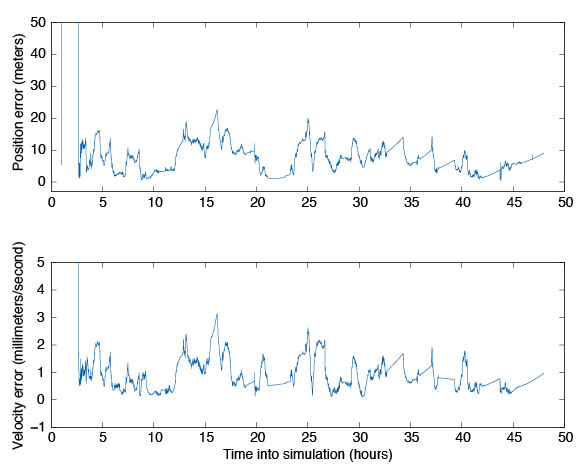
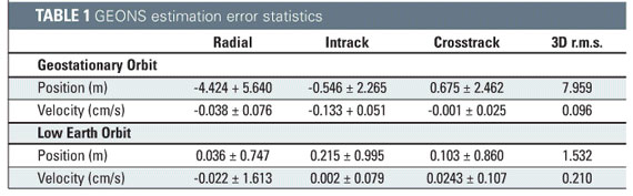
Navigation Filter. To validate the integration of the GEONS software, we compared its estimated states to the true states over the two-day period. These results are plotted in FIGURE 6. For this simulation, we assumed that GPS satellite clock and ephemeris errors could be corrected by applying NASA’s Global Differential GPS System corrections, and errors caused by the ionosphere could be removed by masking signals that passed close to the Earth’s limb. The truth environment consisted of a 70X70 degree-and-order gravity model and sun-and-moon gravitational effects, as well as drag and solar-radiation pressure forces. GEONS internally modeled a 10X10 gravity field, solar and lunar gravitational forces, and estimated corrections to drag and solar-radiation pressure parameters. (Note that drag is not a significant error source at these altitudes.) Though the receiver produces pseudorange, carrier-phase, and Doppler measurements, only the pseudorange measurement is being processed in GEONS.
Figure 6. GEONS state estimation errors for GEO simulation.
The results, compiled in TABLE 1, show that the 3D root mean square (r.m.s.) of the position error was less than 10 meters after the filter converges. The velocity estimation agreed very well with the truth, exhibiting less than 1 millimeter per second of three-dimensional error. Navigator can provide excellent GPS navigation data at low Earth orbit as well, with the added benefit of near instantaneous cold-start signal acquisition. For completeness, the low Earth orbit results are included in Table 1.
Navigator’s Future
Navigator’s unique features have attracted the attention of several NASA projects. In 2007, Navigator is scheduled to launch onboard the Space Shuttle as part of the Hubble Space Telescope Servicing Mission 4: Relative Navigation Sensor (RNS) experiment. Additionally, the Navigator/GEONS technology is being considered as a critical navigational instrument on the new Geostationary Operational Environmental Satellites (GOES-R).
In another project, the Navigator receiver is being mated with the Intersatellite Ranging and Alarm System (IRAS) as a candidate absolute/relative state sensor for the Magnetospheric Multi-Scale Mission (MMS). This mission will transition between several high-altitude highly elliptical orbits that stretch well beyond GEO. Initial investigations and simulations using the Spirent simulator have shown that Navigator/GEONS can easily meet the mission’s positioning requirements, where other receivers would certainly fail.
Conclusion
NASA’s Goddard Space Flight Center has conducted extensive test and evaluation of the Navigator GPS receiver and GEONS orbit determination filter. Test results, including data from RF signal simulation, indicate the receiver has been designed properly to autonomously calculate precise orbital information at altitudes of GEO and beyond. This is a remarkable accomplishment, given the weak GPS satellite signals observed at these altitudes. The GEONS filter is able to use the measurements provided by the Navigator receiver to calculate precise orbits to within 10 meters 3D r.m.s. Actual flight test data from future missions including the Space Shuttle RNS experiment will provide further performance characteristics of this equipment, from which its suitability for higher orbit missions such as GOES-R and MMS can be confirmed.
Manufacturers
The Navigator receiver was designed by the NASA Goddard Space Flight Center Components and Hardware Systems Branch (Code 596) with support from various contractors. The 12-channel STR4760 RF GPS signal simulator was manufactured by Spirent Communications (www.spirentcom.com).
FURTHER READING
1. Navigator GPS receiver
“Navigator GPS Receiver for Fast Acquisition and Weak Signal Tracking Space Applications” by L. Winternitz, M. Moreau, G. Boegner, and S. Sirotzky, in Proceedings of ION GNSS 2004, the 17th International Technical Meeting of the Satellite Division of The Institute of Navigation, Long Beach, California, September 21–24, 2004, pp. 1013-1026.
“Real-Time Geostationary Orbit Determination Using the Navigator GPS Receiver” by W. Bamford, L. Winternitz, and M. Moreau in Proceedings of NASA 2005 Flight Mechanics Symposium, Greenbelt, Maryland, October 18–20, 2005 (in press). A pre-publication version of the paper is available online at http://www.emergentspace.com/pubs/Final_GEO_copy.pdf.
1. GPS on high-altitude spacecraft
“The View from Above: GPS on High Altitude Spacecraft” by T.D. Powell in GPS World, Vol. 10, No. 10, October 1999, pp. 54–64.
“Autonomous Navigation Improvements for High-Earth Orbiters Using GPS” by A. Long, D. Kelbel, T. Lee, J. Garrison, and J.R. Carpenter, paper no. MS00/13 in Proceedings of the 15th International Symposium on Spaceflight Dynamics, Toulouse, June 26–30, 2000. Available online at http://geons.gsfc.nasa.giv/library_docs/ISSFDHEO2.pdf.
1. GPS for spacecraft formation flying
“Autonomous Relative Navigation for Formation-Flying Satellites Using GPS” by C. Gramling, J.R. Carpenter, A. Long, D. Kelbel, and T. Lee, paper MS00/18 in Proceedings of the 15th International Symposium on Spaceflight Dynamics, Toulouse, June 26–30, 2000. Available online at http://geons.gsfc.nasa.giv/library_docs/ISSFDrelnavfinal.pdf.
“Formation Flight in Space: Distributed Spacecraft Systems Develop New GPS Capabilities” by J. Leitner, F. Bauer, D. Folta, M. Moreau, R. Carpenter, and J. How in GPS World, Vol. 13, No. 2, February 2002, pp. 22–31.
1. Fourier transform techniques in GPS receiver design
“Block Acquisition of Weak GPS Signals in a Software Receiver” by M.L. Psiaki in Proceedings of ION GPS 2001, the 14th International Technical Meeting of the Satellite Division of The Institute of Navigation, Salt Lake City, Utah, September 11–14, 2001, pp. 2838–2850.
1. Testing GPS receivers before flight
“Pre-Flight Testing of Spaceborne GPS Receivers Using a GPS Constellation Simulator” by S. Kizhner, E. Davis, and R. Alonso in Proceedings of ION GPS-99, the 12th International Technical Meeting of the Satellite Division of The Institute of Navigation, Nashville, Tennessee, September 14–17, 1999, pp. 2313–2323.
BILL BAMFORD is an aerospace engineer for Emergent Space Technology, Inc., in Greenbelt, Maryland. He earned a Ph.D. from the University of Texas at Austin in 2004, where he worked on precise formation flying using GPS as the primary navigation sensor. As an Emergent employee, he has worked on the development of the Navigator receiver and helped support and advance the NASA Goddard Space Flight Center’s Formation Flying Testbed. He can be reached at [email protected].
LUKE WINTERNITZ is an electrical engineer in hardware components and systems at NASA’s Goddard Space Flight Center in Greenbelt, Maryland. He has worked at Goddard for three years primarily in the development of GPS receiver technology. He received bachelor’s degrees in electrical engineering and mathematics from the University of Maryland, College Park, in 2001 and is a part-time graduate student there pursuing a Ph.D. He can be reached at [email protected].
CURTIS HAY served as an officer in the United States Air Force for eight years in a variety of GPS-related assignments. He conducted antijam GPS R&D for precision weapons and managed the GPS Accuracy Improvement Initiative for the control segment. After separating from active duty, he served as the lead GPS systems engineer for OnStar. He is now a systems engineer for Spirent Federal Systems in Yorba Linda, California, a supplier of high-performance GPS test equipment. He can be reached at [email protected].