Tag: GPS constellation

  • Directions 2013: Plans Set in Motion for GPS

    GPS Directorate: Receivers Will Operate in Environments Impossible Today

    By Col. Bernie Gruber

    Headshot: Col. Bernie Gruber

    I believe the future of global navigation satellite systems (GNSS) and particularly GPS will only be limited by our ingenuity and imagination. In terms of economic benefit, GPS contributes $60 billion to our economy, and that’s no stretch considering the positive and real advantages GPS affords us every day through fuel savings, transportation optimization, banking transactions, recreational activities, and certainly the defense of our great nation.

    GPS consists of three segments — space, ground and user equipment — all contributing synchronistically to provide the world positioning, navigation, and timing (PNT). Having joined the GPS program office (for the first time) in 1992, I was privileged to lead the very first Foreign Military Sales contracts and the development of the Selective Availability Anti-Spoofing module (SAASM) — both focused within the realm of user equipment. As program director of GPS reflecting back on the monumental change of the past 20 years, I am encouraged and look forward to seeing the fruition of the projects and plans we have already set in motion for the next 20. This is why:

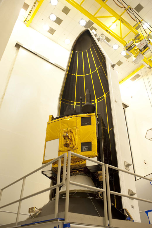
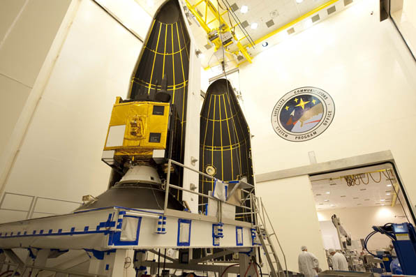
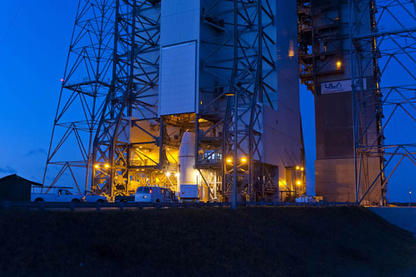
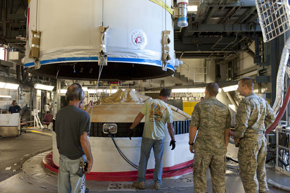
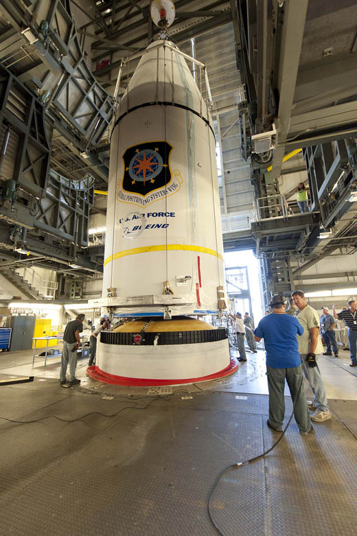
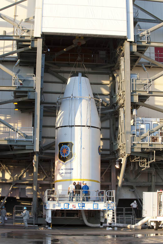
    Space Segment. The launch and handover of the third GPS IIF satellite on October 4 proves once again our commitment to mission success. We have exceeded our published worldwide accuracy standard since 1993, and the NavStar GPS constellation remains robust with 31 satellites currently available.

    In regards to the satellite systems, next-generation Block IIF and III satellites are in various states of test, integration, or production in an effort to improve the average user range error (URE) from 0.9 meters, achieved and maintained for the last 3 years, to a root-mean-squared URE of 0.5 meters by 2016. Along with increased civil and military signals, I also envision digital waveform generation (that is, the ability to change on-orbit signals in space via software) as an integral part of our architecture.  Digital waveform generation coupled with an augmentation of the GPS III constellation for affordability and resiliency will pave our way to the future.

    Ground Segment. Along with a host of additional satellite capabilities and signals, we will correspondingly modernize our ground segment. Our Next-Generation Operational Control System (OCX) is designed to command and control our modernized secondary civil signal L2C, safety-of-life signal L5, and the internationally compatible signal L1C. In fact, users such as John Deere and NavCom are already accessing the currently broadcast L1 C/A and L2C (with a default code) for dual-frequency ionospheric correction to improve upon accuracy. As the modernized signals become operational, users will see faster signal acquisition, enhanced reliability, and a greater operating range. The information assurance, expandability, and service-oriented architecture will afford users and operators with security and information they simply don’t have today.

    User Segment. All that said, I am thrilled to look at the future of user equipment. We need to take advantage of the use of civil GPS. Apple and Android have shown the way to interface with and use applications, displays, and packaging; Google Map overlays, smart phone apps, time-to-first-fix augmentations from cell towers, and multi-GNSS international coverage are already in use, with the growth of apps, users will only get smarter and more sophisticated in their GPS expectations.

    To that end, the Air Force is augmenting its pilots with digital maps and starting to integrate GPS with the digi-maps beginning with the C-130J. The Army is paving the way with an app store for military use and beginning to integrate GPS with its equipment, such as the use of a GPS integrated wind app for calibrating bullet trajectories.

    Security, authentication, integrity, and the ability to operate in almost any environment is vital to our warfighters. The Department of Defense is posturing to operate in an anti-access area denial (A2AD) environment. Make no mistake; the list of potential adversaries also includes a list of known attacks on GPS — along with use of GPS and other GNSS systems against us. For that purpose, the modernized GPS is working on better and improved items like key management, M-Code power and cryptography, and Blue Force Electronic Attack (BFEA). In this area too, I see the commercial market burgeoning with new ideas to protect the calculation of GPS PNT solutions.

    In the selective-availability anti-spoofing module, we introduced positive control and resiliency to the military GPS receivers. Now with M-Code we are taking it one step further. M-code will leverage the National Security Agency (NSA) Key Management Infrastructure and augment it with more tools to ensure only authorized users have access to M-Code. This provides greater protection from spoofing, ensures that keys are readily available to the United States and her Coalition partners, and that security cost drives for our user equipment are minimized.

    With more signal power, almost every aspect of GPS is better. While the 6–10 dB of additional power in GPS III will not in itself defeat known threats, more power complements anti-jam techniques as well as improves operation under foliage and in the presence of pervasive unintentional interference. We’re going to see receivers that operate in navwar environments that would be impossible today. Similarly, I see us having the flexibility to operate with other GNSS systems in benign environments, but the ability to also operate in hostile or contested environments.

    Blue Force Electronic Attack was always a principle driver for GPS modernization. It is embodied in the White House Directives and Title 10 U.S.C [Title 10 of the United States Code outlines the role of armed forces in the U.S. Code, a compilation and codification of the general and permanent federal laws of the United States — Ed.] Today’s Block II systems do not have enough spectral separation for effective BFEA. As M-Code becomes readily available, along with the additional filtering available in military GPS user equipment (MGUE), we are providing Joint Task Force Commanders with options to deny GPS; options that they don’t have today.

    The future of GPS is bright indeed! From the originators of GPS to present day men and women who work tirelessly to deliver and operate it, we are all striving to improve and enhance this magnificent capability. The economic benefits of a system that, in reality, pays for itself guarantees the world’s desire to see improvements and growth in the overall GPS system. The Air Force is a proud steward of the GPS system, but it is our collective job to proliferate new ideas to use it and secure it.


    Colonel Bernie J. Gruber is director, Global Positioning Systems (GPS) Directorate, Space and Missile Systems Center, Air Force Space Command, Los Angeles Air Force Base, California. He is responsible for a multiservice, multinational systems directorate which conducts development, acquisition, fielding and sustainment of all GPS space segment, satellite command and control (ground) and military user equipment. The $32 billion GPS program, with a $1 billion annual budget, maintains the largest satellite constellation and the largest avionics integration and installation program in the Department of Defense. He has served in key positions at Major Command, Air Staff, Joint Staff and Defense Agency levels. Prior to assuming his current position, Colonel Gruber was Chief, Space Superiority and Global Integrated Intelligence, Surveillance and Reconnaissance Division, Directorate of Programs, Deputy Chief of Staff, Strategic Plans and Programs, Headquarters, United States Air Force, Washington, D.C.

  • Lockheed Martin Completes Environmental Test on GPS III Pathfinder

    The Lockheed Martin team developing the U.S. Air Force’s next generation Global Positioning System III  satellites has completed thermal vacuum testing for the Navigation Payload Element (NPE) of the GPS III Non-Flight Satellite Testbed (GNST). The milestone is one of several environmental tests verifying the navigation payload’s quality of workmanship and increased performance compared to the current generation of satellites, the company said.

    The GPS III program will affordably replace aging GPS satellites, while improving capability to meet the evolving demands of military, commercial and civilian users. GPS III satellites are expected to deliver better accuracy and improved anti-jamming power while enhancing the spacecraft’s design life and adding a new civil signal designed to be interoperable with international global navigation satellite systems.

    “GPS III satellites have the most advanced navigation payloads ever manufactured.  This milestone is a key indicator that we have a solid design and are on track to provide unprecedented position, navigation, and timing capability for GPS users worldwide,” said Lt. Col. Todd Caldwell, the U.S. Air Force’s GPS III program manager.

    During thermal vacuum testing, the navigation payload’s performance was proven in a vacuum environment at the extreme hot and cold temperatures it will experience on orbit to ensure it will operate as planned once in space. Following the test, the NPE will now be integrated with the GNST for final satellite level testing.

    The GNST is a full-sized prototype of a GPS III satellite used to identify and solve development issues prior to integration and test of the first space vehicle. The approach significantly reduces risk, improves production predictability, increases mission assurance and lowers overall program costs. Following integration and test at Lockheed Martin’s GPS Processing Facility (GPF) near Denver, the GNST will be shipped to Cape Canaveral Air Force Station, Fla., for risk reduction activities at the launch site.

    “The completion of thermal vacuum testing on our first navigation payload is a critical milestone for our program that demonstrates we are on a solid path to meet our commitments,” said Keoki Jackson, vice president of Lockheed Martin’s Navigation Systems mission area. “The Air Force’s early investment in our GPS III pathfinder is now paying off and will enable highly efficient and affordable satellite production going forward.”

    Lockheed Martin is on contract to deliver the first four GPS III satellites for launch. The Air Force plans to purchase up to 32 GPS III satellites.

    The GPS III team is led by the Global Positioning Systems Directorate at the U.S. Air Force Space and Missile Systems Center. Lockheed Martin is the GPS III prime contractor with teammates ITT Exelis, General Dynamics, Infinity Systems Engineering, Honeywell, ATK and other subcontractors. Air Force Space Command’s 2nd Space Operations Squadron (2SOPS), based at Schriever Air Force Base, Colo., manages and operates the GPS constellation for both civil and military users.

  • GPS IIF-3 Satellite Now Transmitting L1, L2 Signals

    Credit: ULA/Atkeison
    A Delta IV rocket lifts-off into the blue skies over Cape Canaveral on Thursday with an advanced GPS satellite. (Credit: ULA/Atkeison).

    Video of launch.

    UPDATE: The SVN65/PRN24 L5 transmitter has now been switched on. L5 is the civilian safety-of-life GPS signal, designed to meet demanding requirements for safety-of-life transportation and other high-performance applications.

    UPDATE: The GPS Block IIF-3 satellite, SVN65, began transmitting L1 and L2 signals as PRN24 on October 8. A number of stations of the International GNSS Service are now tracking the satellite. The satellite is included in broadcast almanacs although it is set unhealthy and will continue to be so until satellite commissioning is completed. The satellite is still drifting towards its designated orbital position of Slot 1 in Plane A.

    Meanwhile, SVN27/PRN27 was decommissioned from active service on October 6 and removed from the broadcast almanacs. However, the L-band
    transmitters of SVN27 remain active, presumably for end-of-life testing.


    UPDATE: According to Boeing, the satellite manufacturer, SVN65 is on orbit and performing as expected. A Boeing press release stated that “Controllers confirmed initial contact with the spacecraft at 11:43 a.m. Eastern time. The satellite’s GPS signals will be turned on and tested within a few days.”

    Incidentally, the launch occurred exactly 55 years to the day after the launch of the world’s first satellite, Sputnik I, on October 4, 1957. It was Doppler tracking of that satellite that gave rise to the Transit navigation system and subsequently, its successor, GPS.


    The launch of the GPS Block IIF-3 satellite took place as scheduled October 4 at 12:10 UTC (8:10 a.m. EDT), aboard a United Launch Alliance Delta IV rocket from Cape Canaveral, Florida. Spacecraft separation was reported at 16:27 UTC.

    The Boeing-built spacecraft is designed to improve network coverage for both civilian and military networks, including a new L5 signal for improved commercial and civil aviation users.

    The satellite, also known as SVN65, will be positioned in orbital slot 1, which is in plane A and will use the PRN24 ranging codes. Slot 1 was recently occupied by a Block IIA satellite, SVN39, operating as PRN09. SVN39 is one of the oldest operating satellites in the GPS fleet, having been launched on 26 June 1993. SVN39 underwent an initital Delta-V on September 27 to move it close to SVN38/PRN08 in slot 3 in plane A, making room for the new Block IIF satellite.

    “Congratulations to the entire team on today’s successful launch of the GPS 2F-3 satellite,” Jim Sponnick, ULA vice president, Mission Operations, said in a post-launch press release.

    “ULA and our mission partners have a rich heritage with the GPS program and we are proud to have served alongside the government and contractor teams over the last two decades to provide important Global Positioning System capabilities for our national defense and for millions of civilian and commercial users around the world.”

    Credit: ULA/Atkeison
    A Delta IV rocket lifts-off with an advanced GPS satellite from Cape Canaveral on Thursday. (Credit: ULA/Atkeison).


    An NANU announcing the launch has been issued:

    NOTICE ADVISORY TO NAVSTAR USERS (NANU) 2012062
    SUBJ: SVN65 (PRN24) LAUNCH JDAY 278
    1.     NANU TYPE: LAUNCH
    NANU NUMBER: 2012062
    NANU DTG: 041222Z OCT 2012
    SVN: 65
    PRN: 24
    LAUNCH JDAY: 278
    LAUNCH TIME ZULU: 1210

    2. GPS SATELLITE SVN65 (PRN24) WAS LAUNCHED ON JDAY 278.
    A USABINIT NANU WILL BE SENT WHEN THE SATELLITE IS SET ACTIVE TO
    SERVICE.

    3. POC: CIVILIAN – NAVCEN AT 703-313-5900, HTTP://WWW.NAVCEN.USCG.GOV
    MILITARY – GPS OPERATIONS CENTER AT HTTPS://gps.afspc.af.mil/
    GPSOC , DSN 560-2541,
    COMM 719-567-2541, [email protected] , HTTP://gps.afspc.af.mil/GPSOC/GPS
    MILITARY ALTERNATE – JOINT SPACE OPERATIONS CENTER, DSN 276-3514.
    COMM 805-606-3514.
    [email protected]

  • GPS IIF Launch Set for Thursday

    Photos from United Launch Alliance
    Photos from United Launch Alliance

    Lift-off is set for 8:10 a.m. EDT (1210 GMT) Thursday for a GPS IIF satellite, reports Spaceflight Now. GPS IIF-3 will replace an aging 19-year-old craft in plane A, slot 1, part of the program to incrementally upgrade the GPS constellation with greater accuracy, better jam-resistance, and a new civilian aviation signal, all of which are features of the Boeing-build Block IIF series.

    The United Launch Alliance Delta 4 rocket and GPS satellite payload will undergo a final technical assessment today and a readiness review Tuesday before entering into countdown operations Wednesday night.

    The 19-minute launch window is timed to deliver the GPS IIF-3 satellite directly into plane A of the navigation network 11,000 miles above Earth.

    The satellite is expected to be checked out and ready for handover to Air Force controllers by mid-November, according to Jan Heide, Boeing’s GPS program director.

    Photos from United Launch Alliance:

  • Lockheed, Raytheon Complete First Launch Exercise for Next-Gen GPS Satellites

    Raytheon Company and Lockheed Martin have successfully completed the first launch readiness exercise for the U.S. Air Force’s next generation GPS III satellites. The exercise is a key milestone demonstrating the team remains on schedule to achieve launch availability in 2014, the companies said.

    The Lockheed Martin-built GPS III satellites and the Raytheon-developed next generation GPS operational control system, known as OCX, are critical elements of the U.S. Air Force’s effort to affordably replace aging GPS satellites while improving capability to meet the evolving demands of military, commercial and civilian users worldwide. This is the first space and ground enterprise successfully building the ground control and space vehicles by two independent prime contractors.

    The launch readiness exercise, completed over a three day period by mission operations personnel, validated the basic satellite command and control functions, tested the software and hardware interfaces and demonstrated basic on-console procedures required for space vehicle contacts during the launch and early orbit mission.  The event sets the stage for the first GPS III satellite’s mission readiness timeline, which includes five short-duration exercises and six, five-day mission rehearsals leading up tolaunch.

    “Completion of our first GPS III launch readiness exercise is a major milestone for the entire GPS enterprise and is a solid indictor that our space and ground segments are well synchronized,” said Col Bernie Gruber, the director of the U.S. Air Force’s Global Positioning Systems Directorate.

    To achieve first launch availability in the 2014 timeframe, the U.S. Air Force awarded Lockheed Martin and Raytheon contracts in January of this year to provide a Launch and Checkout Capability (LCC) for launch and early on-orbit testing of all GPS III satellites.  At the heart of the LCC is Raytheon’s Launch and Checkout System that will provide satellite command and control capability, an integral part of OCX’s  support of the first GPS III launch.

    “The completion of our first launch readiness exercise is an important milestone for the entire GPS enterprise,” said Keoki Jackson, vice president of Lockheed Martin’s Navigation Systems mission area. “This achievement is a testament to efficient planning and synchronization by the U.S. Air Force and demonstrates that we are on track to deliver critical GPS III capabilities to military, commercial and civilian users worldwide.”

    “This milestone represents the hard work and dedication of the entire GPS III and OCX government-industry team,” stated Ray Kolibaba, a vice president of Raytheon’s Intelligence and Information Systems business and GPS OCX program manager. “This is another demonstration of the rapid progress we’re making on OCX development, while maintaining GPS space-ground enterprise alignment. I’m confident that we’ll be prepared to support the first GPS III launch with an efficient, evolvable and secure ground control system built independently.”

    The GPS III team is led by the Global Positioning Systems Directorate at the U.S. Air Force Space and Missile Systems Center. Air Force Space Command, based at Schriever Air Force Base, Colo., manages and operates the GPS constellation for both civil and military users.

  • Next GPS IIF Satellite Launch Expected October 4

    News courtesy of CANSPACE Listserv.


    Spaceflight Now is reporting that the next GPS satellite, Block IIF-3 (SVN65) to be launched on October 4, 2012, will be positioned in orbital slot 1, which is in plane A. This slot is currently occupied by a Block IIA satellite, SVN39, operating as PRN09. SVN39 is one of the oldest operating satellites in the GPS fleet, having been launched on June 26, 1993.

    This will be the third satellite in the Block IIF series of GPS spacecraft with improved accuracy, enhanced internal atomic clocks, better anti-jam resistance, a civil signal for commercial aviation (and others) and a longer design life. Boeing is building a dozen craft to upgrade the constellation’s foundation over the coming years.

  • GPS SVN49 Resumes Transmissions Using PRN24

    News courtesy of CANSPACE Listserv.


    The GPS Block IIR-M satellite, SVN49, resumed transmissions as PRN24 at about 18:35 UTC on August 9, 2012. The signals are marked unhealthy and the satellite is not included in broadcast almanacs. SVN49 was launched on March 24, 2009, but remains out of service until an L1/L2 satellite multipath issue is resolved.

    Although not in the almanacs, a number of stations of the International GNSS Service are tracking SVN49. See: http://gge.unb.ca/test/IGS_stns_tracking_G24_223.pdf

    SNV49 previously operated between March 28, 2009, and May 6, 2011, as PRN01 and between February 2 and March 14, 2012, as PRN24.

  • On the Edge: Five Big Ones in Ten


    Look back with me at the five 2010 GNSS events that most affected surveying, mapping, engineering, construction, and natural resource users. Each one had, or could have had, a significant effect on you and your work. Taking it from the top:

    GPS 24+3 Constellation. The most important event occurred a year ago, when the Air Force began implementing a new GPS 24+3 configuration. They had their military reasons, but the benefit for you and me is eliminating GPS brownouts — periods with fewer GPS satellites in view. When combined with obstructions such as terrain, trees, or buildings, they made GPS hard to use.

    It’s especially an issue with real-time kinematic (RTK) high-precision users because RTK technology is satellite-hungry. It needs six or more satellites to provide a robust position solution.

    The Air Force moved three satellites, SVNs 24, 26 and 30, from their original slots. SVNs 26 and 30 have already reached their destinations, and SVN 24 will do so this month.

    Three other satellites are being shifted slightly. SVN 55 found its new slot in December, while SVNs 46 and 56 start this month and should have completed their journeys by May/June 2011.

    By now, you should be seeing some improvements in GPS satellite visibility. Although you’ll see fewer peaks (high number of GPS satellites in view), you’ll also see fewer valleys (low number of GPS satellites in view). This should increase productivity for RTK users and those in obstructed environments such as tree canopy.

    First GPS Block IIF. Although it doesn’t really help users at this point other than being another satellite to enter service, the Block IIF satellite launched in May is the first to broadcast the third civil signal. L5 marks the beginning of a new era in high-precision GPS positioning. The Block IIF launch was the catalyst for my June column “What Happen When High Accuracy is Cheap?”

    This IIF is just a teaser though, and its fellows will launch at a snail’s pace. Remember though, it costs upwards of $200 million to launch a satellite and since there ares already 30+ operational GPS satellites in orbit, it’s hard for Congress and the Air Force to justify speeding up the launch schedule. The last target I heard was to have 24 satellites broadcasting L5 by 2019.

    GLONASS Growth. Despite the recent catastrophe, the Russian Federation was still able to launch seven new satellites in 2010, including a new K1 satellite that will test a new CDMA signal for better compatibility with GPS.With 21 operational satellites and three more coming in March, a consistent and healthy number of GLONASS satellites in orbit has given receiver manufacturers more confidence to develop GPS/GLONASS receivers. This year, we’ve seen several manufacturers integrating GPS/GLONASS into handheld receivers as well as OEM board products.

    User benefits are clear: more robust positioning and improved productivity due to decreased down-time.

    Solar Activity. The big news is no news: the sun was eerily quiet in 2010. If your GPS receiver didn’t work at times this year, it wasn’t due to solar activity. But it may ramp up in 2011.

    GAGAN, WAAS Failures. The Indian Space Research Organisation and the U.S. Federal Aviation Administration received a hard lesson in SBAS GEO management. In April, an Indian rocket launch failed, and one of the FAA WAAS satellites lost communication with its ground control.

    If you’re an SBAS user, don’t let it bring you down. SBAS is here to stay, and likely you were not affected by either incident — unless you work in northwest Alaska. A new U.S. SBAS satellite came online, and India is regrouping for more launches.

    Follow Eric on Twitter at GISGPS_Eric.

  • The System: Three’s the Challenge

    A Close Look at GPS SVN62 Triple-Frequency Signal Combinations Finds Carrier-Phase Variations on the New L5

    By Oliver Montenbruck, André Hauschild (DLR/German Space Operations Center), Peter Steigenberger (Technische Universität München), and Richard B. Langley (University of New Brunswick)

    The recently launched Block IIF satellite (SVN62/PRN25) is the first of a new generation of GPS satellites designed to transmit ranging signals for civil users on three frequencies: the C/A-code on L1 at 1575.42 MHz, the L2C-code on L2 at 1227.60 MHz, and the I5/IQ codes on L5 at 1176.45 MHz. Unlike L2, the L5 signal is located inside the protected Aeronautical Radionavigation Services (ARNS) band, which makes it specifically useful for safety critical aviation applications. In combination with the legacy L1 signal, civil aviation users can now perform ionospheric corrections without referring to the L2C signal. Compared to L2C, the new L5 signal offers a much higher chipping rate (the same as the encrypted P-code signal) of 10.23 MHz, which promises a lower ranging noise and better multipath resistance. L5 signals have already been transmitted for some time by the geostationary satellites of the United States’ Wide Area Augmentation System (WAAS) and are now about to become an integral part of the GPS constellation.

    Following a short test transmission on June 17, 2010, the L5 signal was continuously activated on the morning of June 28. According to GPS officials, the checkout of the satellite is proceeding nominally and all signals have been found to fully comply with specifications. This will allow the satellite to be set healthy as soon as all commissioning tasks have been completed.

    Scientists have long discussed the potential of new signals for multi-frequency, multi-GNSS applications, and expresed a great interest in signal combinations, particularly those of carrier-phase measurements, involving all three frequencies simultaneously. The use of triple-frequency combinations has, for example, been demonstrated to be of great interest for ambiguity resolution in precise carrier-phase-based positioning, for receiver autonomous integrity monitoring, and for ionospheric research (see the articles in Further Reading).

    In consideration of the multitude of proposed applications for triple-frequency combinations, we took a close look at the quality of the new GPS L5 carrier-phase signal. For this purpose, we made use of measurements from the COoperative Network for GIOVE Observation (CONGO), jointly established by the German Federal Agency for Cartography and Geodesy (BKG) and the German Aerospace Center (DLR). CONGO is the first network of multi-constellation, multi-frequency GNSS receivers offering worldwide tracking of the SVN62 space vehicle on all frequencies (see Table 1).

    Table 1. Subset of CONGO stations used for triple-frequency tracking of the new Block IIF satellite.
    Table 1. Subset of CONGO stations used for triple-frequency tracking of the new Block IIF satellite.

    As suggested by Andrew Simsky (see Further Reading), the availability of carrier-phase measurements on three frequencies offers a particularly simple way to assess carrier-phase quality and multipath effects. By forming a linear combination

    E1a   (1)
    of the L1, L2, and L5 carrier-phase ranges with the additional conditions
    E2,
    a geometry- and ionosphere-free measurement is obtained, which reflects a weighted sum of the carrier-phase multipath and measurement noise on the individual frequencies. Here λ i with i = 1, 2, and 5, denotes the wavelength of the L1, L2, and L5 signals, respectively. Since the above conditions determine the factors α, β, and γ only up to an arbitrary scaling factor, we furthermore impose the normalizing conditionsE1.

    The latter condition ensures that the noise of the tri-carrier combination will match that of the individual carrier phases if the measurement noise is equal on all frequencies. As a result, we obtain the coefficients

    E3

    with
    E4    .
    Introducing the carrier wavelengths of the L1, L2, and L5 signals, the coefficients attain the valuesE5      (2)
    It can be recognized that the tri-carrier combination is dominated by the L2 and L5 signals due to the proximity of their respective frequencies. Noise and multipath errors of L2 and L5 measurements are thus most prominently seen in the resulting combination, whereas any L1 phase errors are strongly attenuated.

    A long pass of L1, L2, and L5 code and phase measurements from the new Block IIF satellite was recorded by the O’Higgins station of the CONGO network shortly after the activation of the L5 signal generator on June 28. The SVN62 satellite was tracked for more than 6 hours and achieved a peak elevation angle of more than 75° on this date.

    Figure 1 shows the resulting multipath combination computed from carrier-phase measurements of L1 C/A-code tracking, semi-codeless L2 P(Y) tracking (rather than L2C), and L5 I/Q tracking. The data have been leveled to a zero mean over the entire pass to remove the impact of the unknown carrier-phase ambiguities. Except at low elevation angles, near rise and set of the satellite where signal strengths are low, the tri-carrier combination shows a very low noise level that is consistent with the expected carrier-phase noise on all three frequencies. However, a pronounced long-term variation with a peak-to-peak amplitude of almost 20 centimeters may be recognized, which certainly comes as a big surprise and cannot be explained by local multipath. Frequency-dependent differences of the effective phase centers of the receiving or transmitting antennas can likewise be excluded, since these would result in a purely elevation-angle-dependent variation.

    FIGURE 1. Triple-frequency (M=0.142·L1-0.767·L2+0.626·L5) carrier-phase multipath combination for SVN62/PRN25 tracking from the OHIX0 station on June 28.
    FIGURE 1. Triple-frequency (M=0.142·L1-0.767·L2+0.626·L5) carrier-phase multipath combination for SVN62/PRN25 tracking from the OHIX0 station on June 28.

    Looking at the entire set of measurements from all available CONGO stations, we could rapidly recognize that the variation of the tri-carrier combination with time is essentially the same for all stations with a common visibility of the SVN62 space vehicle, irrespective of the employed receiver and antenna. This suggests the presence of time-varying inter-frequency biases in the L1, L2, and L5 carriers transmitted by SVN62.

    Thanks to the global distribution of the CONGO stations, the SVN62 space vehicle is always tracked by one or more stations, which enables a continuous monitoring of the L1/L2/L5 carrier-phase consistency. By adjusting the unknown offset of the tri-carrier combination for individual tracking arcs in such a way as to obtain a best match of consecutive and overlapping arcs, the variation can be traced over multiple days as shown in Figure 2. The graph shows a distinct orbital (that is, 12-hour) periodicity with a superimposed twice-per-revolution harmonic. In addition, a pronounced drift can be recognized for up to one day after activation of the L5 signal generator. Both observations suggest a temperature-dependent line bias in one or more carriers as a likely cause of the observed variation in the tri-carrier combination. (A line bias is a circuitry delay common in all observed satellites and is usually absorbed in the estimated clock offset.) However, an independent analysis of SVN62 temperature data from the onboard telemetry will be required to confirm the validity of this assumption. The space vehicle is in a deep eclipse orbit right now and therefore experiences substantial changes in its thermal conditions. However, the extreme points of the carrier-phase variation in Figure 2 are slightly shifted with respect to the local space vehicle noon (at 01:30 and 13:30 UTC) and the eclipse intervals (07:00–08:00 and 19:00–20:00 UTC).

    FIGURE 2. Triple-frequency carrier-phase combination (M=0.142·L1-0.767·L2+0.626·L5) for the first five days of L5 activation on SVN62. The curve has arbitrarily been shifted to obtain a near-zero mean during the final days of the entire arc.
    FIGURE 2. Triple-frequency carrier-phase combination (M=0.142·L1-0.767·L2+0.626·L5) for the first five days of L5 activation on SVN62. The curve has arbitrarily been shifted to obtain a near-zero mean during the final days of the entire arc.

    While the tri-carrier combination provides a very sensitive measurement for the analysis of differential delays between the individual carriers, it does not allow us to uniquely attribute the observed variations to one of the three signals. We therefore made use of code measurements (pseudoranges) to further investigate the consistency of specific sets of measurements. Since the observed variation of the tri-carrier combination exhibits an amplitude comparable to the noise level of the code measurements, a suitably chosen code-carrier combination can indeed help to identify which signal or signals are affected by line-bias variations. To this end, we consider a generalized form

    E6

    of the well-known code-multipath combination, in which we difference the code measurement Pi at frequency i with an ionosphere-corrected combination of carrier-phase ranges Lj and Lk at frequencies j and k. In so doing, we remove geometric contributions along with clock and atmospheric variations, leaving primarily code multipath, receiver noise, and any signal perturbation that is not coherent on the involved frequencies. In the traditional case of dual-frequency tracking, the frequency of one of the involved carrier-phase measurements is necessarily identical to that of the code measurements. With triple-frequency tracking, in contrast, we are free to consider a larger variety of combinations. For the analysis of the SVN62 signals, we have specifically evaluated the L5 code-multipath combination using (a) the L5 and L1 carrier phases

    E7

    and (b) the L2 and L1 carrier-phase measurements

    E8

    The results shown in FIGURE 3 reveal a dramatic difference, which clearly hints at the L5 carrier as the main source of the observed carrier-phase variations.

    FIGURE 3. L5 code-multipath combination formed with L1/L5 carrier-phase measurements (top) and with L1/L2 carrier-phase measurements (bottom). The figure is based on SVN62 tracking from the O’Higgins station and covers the same arc as considered in FIGURE 1.
    FIGURE 3. L5 code-multipath combination formed with L1/L5 carrier-phase measurements (top) and with L1/L2 carrier-phase measurements (bottom). The figure is based on SVN62 tracking from the O’Higgins station and covers the same arc as considered in FIGURE 1.

    In the first case, a variation close to that of Figure 1 is obtained, albeit with a 5–6 times larger amplitude that reflects the different weighting of the L5 carrier phase in the corresponding measurement combinations. A good consistency, in contrast, is obtained for the L5 code measurements when differenced against the ionosphere-corrected combination of L1 and L2 carrier-phase measurements.

    Overall, we may conclude that the L5 carrier of the SVN62 space vehicle exhibits quasi-periodic line-bias variations with an amplitude of about 10 centimeters in relation to the L1 and L2 carriers. The L5 code measurements, in contrast, appear to be consistent with both the code and phase measurements on L1 and L2 at the respective noise levels. Further observations at a later time will be required to see whether the observed amplitude of the L5 phase variation is specific to the current eclipse orbit and whether it will possibly become lower when a higher angle of the Sun with respect to the orbital plane (the so-called beta-angle) is achieved.

    What are the possible consequences of the L5 phase-bias variations for users of the new L5 signal? Evidently, new positioning services building on the L5 code measurements (and possible combinations) will not at all be affected! Even in the case of carrier-phase smoothing, the smoothing time scale will be much shorter than the periodicity of the carrier-phase bias variation. The L5 code measurement quality itself is well within the system specification and no concerns exist that would prevent the satellite from soon being declared healthy.

    With respect to carrier-phase-based positioning applications, it is important to note that the L5 line bias acts like an additional frequency-specific satellite-clock offset. This has, for example, been confirmed in preliminary tests of SVN62 orbit determination conducted by the Technische Universität München. Orbit solutions using L1 and L5 measurements from the CONGO network differed by typically 15 centimeters (3D root-mean-square error) from reference orbits obtained by the Center for Orbit Determination in Europe analysis center using the IGS L1/L2 receiver network. At the same time, however, the L1/L5-based clock solutions showed a periodic offset from the L1/L2-based values that reflects the same variations as the tri-carrier combination discussed above.

    As a common error for all receivers, the L5 line bias fully cancels in differential processing. Care must be taken though, that satellite clock offsets derived from L1/L2 carrier-phase observations cannot be employed for precise point positioning using L1/L5 measurements without explicit consideration of the inter-frequency carrier-phase bias. Likewise, efforts to correct second order ionospheric effects through the use of triple-frequency measurements are likely to suffer from an imperfect knowledge of the L5 bias and its variation with time.

    Whereas some of the proposed ideas for triple-frequency processing may be difficult to materialize at present, a better characterization of the SVN62 L5 signal will certainly help to exploit the available benefits of the new signal and to establish refined processing schemes for scientific and other demanding applications. A continued monitoring of the L5 line bias and its variation with time is therefore deemed necessary and should be supported by a large number of suitably equipped tri-band GNSS monitoring stations.

    — Oliver Montenbruck, Andre Hauschild (DLR/German Space Operations Center),
    Peter Steigenberger (Technische Universität München)
    Richard B. Langley (University of New Brunswick)

    Acknowledgment

    The authors are grateful to Tom Stansell and Col. David Goldstein from the GPS Wing for early discussions and their independent assessment and interpretation of the SVN62 triple-frequency carrier-phase data.

    Equipment

    The CONGO network makes use of Javad Triumph Delta-G2T/G3TH and Leica GRX1200+GNSS GNSS receivers for tracking GPS signals on the L1, L2, and L5 frequencies. The stations are equipped with Trimble Zephyr Geodetic II or Leica AX1203+GNSS and AR25R3 antennas.

    Further Reading

    “The WAAS L5 Signal: An Assessment of Its Behavior and Potential End Use,” by H. Rho and R.B. Langley in GPS World, Vol. 20, No. 5, May 2009, pp. 42–50.

    “Using Multi-Frequency for GPS Positioning and Receiver Autonomous Integrity Monitoring” by Y.-H. Tsai, F.-R. Chang, W.-C. Yang, and C.-L. Ma in Proceedings of the 2004 IEEE International Conference on Control Applications, Taipei, Taiwan, September 2–4, 2004, pp. 205–210.

    “Triple Frequency Ambiguity Resolution Using GPS/Galileo” by O. Julien, M.E. Cannon, P. Alves, and G. Lachapelle in European Journal of Navigation, Vol. 2, No. 2, May 2004, pp. 51–57.

    “Three’s the Charm — Triple Frequency Combinations in Future GNSS” by A. Simsky in Inside GNSS, Vol. 1, No. 5, July/August 2006, pp. 38–41.

    “Total Electron Content Monitoring Using Triple Frequency GNSS Data: A Three-Step Approach” by J. Spits and R. Warnant in Journal of Atmospheric and Solar-Terrestrial Physics, Vo. 70, No. 15, December 2008, pp. 1885–1893, doi:10.1016/j.jastp.2008.03.007.


  • Carrier-Phase Anomalies Detected on SVN-48

    By Brady O’Hanlon, Mark L. Psiaki, Paul M. Kintner Jr., and Steven P. Powell

    Anomalous behavior of the L1 C/A-code carrier phase has been detected on PRN07/SVN-48. The anomalies are sudden step-like changes of phase by about 10 degrees/5 millimeters. These steps are followed by negative steps of the same magnitude that restore the original phase time history. These anomalous square pulses have been observed with durations as short as 0.1 seconds and as long as 600 seconds. They can occur about once a minute or be absent for hours.

    These anomalies could be of consequence for some GNSS applications. For precise monitoring of differential total electron content (TEC), the magnitude of this anomaly is the same order as the signals of interest. Precise point positioning (PPP) systems seek to achieve CDGPS accuracy without direct double-differencing. The lack of double-differencing would allow any L1 C/A carrier phase anomaly to directly affect the PPP solution.

    This behavior was detected when testing a dual-frequency software receiver that processes the GPS civilian signals on L1 and L2. The anomaly was first noted when calculating carrier-phase-based TEC:

    where bTEC is a bias term that occurs in the phase-based calculation. Figure 1 shows a plot of the resulting TEC, after removal of its mean value, with six square-edged pulses that range in duration from 0.1 to 590 seconds, with the first a short one at t = 48 seconds. The last pulse starts at 710 seconds and ends at 1300 seconds. In all cases, the anomaly consists of a positive step change in TEC followed some time later by a negative step change of identical magnitude. Step magnitudes in the range 0.04 to 0.07 TEC units have been observed.

    Figure 1. Square pulses on phase-based TEC due to L1 C/A carrier phase anomalies.

    Tests were performed to ascertain whether the anomalies were caused by the L1 signal, the L2 signal, or a combination of the two. Additional tests ruled out receiver malfunction as the cause of the anomalies.

    Observation of detrended L1 and L2 carrier-phase time histories quickly revealed that the anomalies occur on the L1 carrier phase. The detrended L1 C/A carrier phase shows square-edged pulses corresponding to times, magnitudes, and signs of the TEC anomalies, but the detrended L2C carrier-phase plots show no such pulses. Figure 2 shows a typical detrended L1 C/A beat carrier-phase anomaly.


    Figure 2. A typical detrended L1 C/A beat carrier-phase anomaly.

    Extensive tests checked whether the anomalies may have been caused by the receiver. They were initially discovered using a digital storage receiver of raw RF front-end samples followed by off-line software receiver processing. Such carrier-phase anomalies could result from signal glitches in the RF front-end’s mixing chain, from data recording anomalies in the RF front-end samples, or from errors in the software receiver code. The former two possibilities were ruled out by two means. One was to process signals from other satellites for the same RF samples. Mixing problems or data sample problems would cause similar anomalies on all GPS signals, but other GPS signals were found to be free of anomalies. Additional tests used simultaneous data collection by two digital storage receivers spaced 700 meters apart and using different RF front-end hardware. Both receivers showed identical anomalies at identical times.

    Software receiver code errors were ruled out by employing two independent sets of receiver processing code, one developed in MATLAB, the other in C. These two pieces of software were developed independently by different individuals and run independently by their developers. Both showed identical anomalies.

    A final check used a different receiver, the NovAtel GSV4004B. Figure 2 plots its detrended L1 C/A carrier phase along with that of the C-based Cornell software receiver. Both show the same anomaly. Thus, the anomalies appear to be caused by the SVN-48 transmitter.

    All observations were made from roof-mounted antennas in Ithaca, New York. The anomalies were first observed on March 24, 2010 and were observed again on April 1, 5, 7, and 29, and as late as May 13th. For one period of several hours on May 11, no anomalies occurred. Other Block IIR-M satellites have been monitored briefly, but without finding any similar anomalies to date: SVNs 58, 55, 57, 49, and 50.

  • The Best and Final Look at the GPS 24+3 Configuration

    I didn’t plan it this way, but my coverage of GPS 24+3 turned out to be a three-part series, with this column being part three. One reason it turned into a three-part series is because I’m learning more about it along the way, but its mostly because details weren’t released all at once.

    The good news is that I (along with help from others….thank you) was able to generate an almanac that simulates 24+3 reasonably well. The idea behind doing this is that I could compare the satellite visibility plots in satellite visibility software using both the original almanac (I chose January 1, 2010) and a GPS 24+3 modified version of the same almanac. For those plots, I could present to you what you can realistically expect the improvement to be with the 24+3 satellite configuration.

    A quick note before diving into the 24+3 configuration. At the end of this column is a brief discussion about solar activity and GNSS/GPS. Last week, there was a solar event and some users have voiced concerns about that. I’ve addressed those in a section at the end of this article.


    24+3

    You can view my first two columns relating to the 24+3 configuration by following these links:

    The New GPS 24+3 Constellation: What Does it Mean to the Surveying and GIS User?

    GPS 24+3 Configuration: A Closer Look

    Plus a news article: New Details of 24+3 GPS Configuration Released


    I’d like to update you on some bits of information that I’ve learned about 24+3 since my last column. I asked the HQ Air Force Space Command some questions about 24+3 and they kindly responded.


    EG: Will the satellites (SVN24, SVN26) remain healthy during their repositioning journey?

    HQ AFSC: Yes. The satellites will be set unhealthy for the initial Delta-V, but will return to healthy status approximately 24 hours after initiation of the Delta-V. Initial Delta-V for SVN24 was accomplished on 13 Jan 10 and returned healthy on 14 Jan 10. SVN 24 will take up to a year to reach its final destination. Initial Delta-V for SVN 49 was accomplished on 21 Jan 10 and will arrive at its expanded position in Jun 10.  Initial Delta-V for SVN26 will begin early Feb 10.


    EG: Why the two-year timeframe to realize the benefits when all repositioning will be complete in 12 months?

    HQ AFSC: The two-year timeframe is a conservative estimate which takes into account potential operational necessities which could extend the time required for completion. We must take a disciplined approach to cover possible failures and ensure continuity of coverage during the transition.

    We will be adding GPS IIF vehicles to the constellation and older vehicles may fail during the transition timeframe. As vehicles are added and removed, the current plan is subject to change in order to provide the best service to all civil and military users. Some of these decisions could require additional time to complete the expanded constellation. However, benefits will likely be realized well in advance of 24 months.


    EG: What is the reasoning behind using SVN49 as a key component of the 24+3 configuration since it won’t benefit a significant portion of the civilian user community, namely aviation and marine navigation as well as other SBAS (WAAS) and DGPS users? In my understanding, the FAA’s and the Coast Guard’s user bases are primarily single-frequency pseudo-range, users who won’t be able to use SVN49.

    HQ AFSC:  SVN49 was selected because it is a brand-new satellite with four good clocks. Although issues with SVN49’s navigation signals may make it unusable for all civil use, it could still put out a valid set of signals for military use. The Air Force team is continuing to work “open book” with civil and industry GPS experts to determine the possible outcome of SVN49. Although SVN49 is not currently healthy, GPSW and 50th SW are actively working a mitigation that may allow setting the vehicle healthy in the future. As a mitigation in case we are unable to set SVN49 healthy, SVN30 will be rephased to the same slot following a successful launch and on-orbit checkout of IIF-1. We expect to have either SVN30 or SVN49 healthy and broadcasting from the expanded slot within a 24-month timeframe. At this time, no decisions have been made and no options have been ruled out regarding SVN49.


    Satellite Visibility Plots

    As promised, I’ve (with help) been working on creating an almanac that simulates the 24+3 constellation. My goal was to be able to show you what the benefit to you will be with the new GPS 24+3 satellite configuration.

    The method I used was to modify an almanac from January 1, 2010. The reason I chose that day is because it was before the satellite repositioning began. The first satellite began its repositioning journey on January 13, 2010.

    Within the almanac, I adjusted the position of three of the satellites in the almanac to reflect the new orbit locations they are going to assume.

    • SVN 24 is moving from slot D5 to slot D2F
    • SVN 26 is moving from slot F5 to slot F2F
    • SVN 49 is moving from slot B5 to slot B1F

    Following is a graphic I’ve published before that illustrates the satellite repositioning:

    Using the original January 1, 2010, almanac to plot a satellite visibility chart and then using the 24+3 modified almanac to plot another chart for the same location, I was able to generate the following comparisons between the current GPS satellite configuration and the 24+3 satellite configuration. Please note the following:

    • A 15-degree elevation cutoff was used to account for obstructions (terrain, buildings, trees).
    • The modified almanac does not take into account the other three satellites that are being slightly repositioned (SVN46, SVN55, SVN56) so the modified almanac represents a worst-case scenario.
    • The original almanac is the first plot. The modified 24+3 plot is directly below it.


    Portland, OR USA (N45 41, W122 11) Original Almanac:


    Portland, OR USA (N45 41, W122 11) 24+3 Almanac:


    Miami, FL USA (N25 46, W80 11) Original Almanac:


    Miami, FL USA (N25 46, W80 11) 24+3 Almanac:


    Tokyo, Japan (N35 42, E138 30) Original Almanac:


    Tokyo, Japan (N35 42, E138 30) 24+3 Almanac:


    London, England (N51 30, W000 07) Original Almanac:


    London, England (N51 30, W000 07) 24+3 Almanac:

    src=”/files/gpsworld/nodes/2010/9563/LondonModified.jpg” />


    Moscow, Russia (N55 45, E37 37) Original Almanac:


    Moscow, Russia (N55 45, E37 37) 24+3 Almanac:


    New Dehli, India (N28 54, E77 13) Original Almanac:


    New Dehli, India (N28 54, E77 13) 24+3 Almanac:


    Rio De Janeiro, Brazil (S22 27, W42 43) Original Almanac:


    Rio De Janeiro, Brazil (S22 27, W42 43) 24+3 Almanac:


    Bangkok, Thailand (N13 49, E100 28) Original Almanac:


    Bangkok, Thailand (N13 49, E100 28) 24+3 Almanac:


    Perth, Australia (S31 49, E116 10) Original Almanac:


    Perth, Australia (S31 49, E116 10) 24+3 Almanac:


    A Quick Note about Solar Activity and GNSS/GPS

    I’ve read media reports and I’ve been asked about a solar event that occurred last week (Thursday, February 12) and what possible effect it had on GPS operations.

    I consulted with Joe Kunches of the NOAA Space Weather Prediction Center to understand how significant of an event it was.

    “There was some activity but I would not think it would have an impact on GPS,” stated Kunches.

    I asked him at what point would GPS operations be affected.

    “As for flares (Radio Blackouts on the NOAA Scales), I’d say 10 to 20 times stronger than last week (R3 to R4 and above) would be sufficient to affect GPS on the dayside, but not for long,” said Kunches.

    So, although there were media reports about the solar event last Thursday, if you had trouble with your GPS it wasn’t due to solar activity.

    However, solar activity is a serious issue for GPS users, especially those using high-performance L1 receivers (sub-meter). You can be sure that I’ll will be covering this subject in-depth as we move further into the current solar cycle.


    Thanks, and see you next time.

    Follow me on Twitter at http://twitter.com/GPSGIS_Eric.

    If you haven’t seen the announcement regarding my Webinar this Thursday (February18, 10 a.m. Pacific Time, 1800 hrs GMT), you might be interested. The title is “GPS for GIS – 101.” It’s a beginner’s (and refresher’s) guide to using GPS for GIS data collection. I’ve invited Craig Greenwald as Guest Commentator.

  • GPS 24+3 Configuration: A Closer Look

    In the few years I’ve been writing this column, very few subjects have warranted back-to-back newsletter coverage. The new GPS 24+3 onfiguration is one of them. The reason I’ve continued with this discussion is because it will significantly affect your GPS operations, especially if you’re using RTK or DGPS.

    What is the new 24+3 GPS configuration?

    If you didn’t read my last column, you might want to read it so you have a common frame of reference. Essentially, the effect of the 24+3 configuration will be to increase the visibility of more GPS satellites throughout the day at a given location. In addition to have more satellites in view, you will generally see lower PDOP values which can result in an increase in accuracy; but certainly the increased satellite visibility is the major upside with 24+3.

    Remember that the GPS satellites are configured in 6 orbital planes (A, B, C, D, E, F) with X number of satellites in each plane that are referred to as “slots.” For example, slot A1 is the first satellite in the A plane, slot B4 is the fourth satellite in the B plane. Note that the slots aren’t necessarily in numerical order. Following is a graphic presented by the U.S. Air Force in September 2009 to provide an illustration of the planes, and slots within each plane. GLAN is the Geographic Longitude of the Ascending Node.

    On the graphic above, note that many of the satellites are paired together. When GPS satellites are paired together, there is little benefit to the user on the ground because the satellites aren’t “spread out”. Ideally, the user on the ground needs the satellites to be “spread out” in the sky which will result in a lower PDOP value (better constellation geometry) and ultimately better accuracy. The satellites are in this configuration today because GPS policy defines a 21+3 configuration. Since there are 30 operational GPS satellites in orbit (six more than required), the six spares are placed near other operational satellites. This isn’t optimal for the user on the ground.

    The concept behind the 24+3 configuration is to spread out the satellites more than the current configuration to benefit users on the ground. This involves significantly repositioning three GPS satellites (SVN24, SVN26, SVN49) and slightly repositioning three other GPS satellites (SVN56, SVN46, SVN55).

    Following is a tabular listing of each slot in the 21+3 configuration. Please note that the graphic above is a rough graphic for illustration purposes (referencing GLAN) while the tabular data below are the actual values.


    Notes:

    Epoch: 00:00:00 UTC, 1 July 1993
    Greenwich Hour Angle: 18h 36m 14.4s
    Orbital Slot IDs are Arbitrarily Numbered
    * Orbital Slots Marked by an Asterisk are Expandable


    In the 24+3 configuration, slots B1, D2, F2 are split to B1F/B1A, D2F/D2A, and F2F/F2A. The F designation is Fore and the A designation is Aft.

    Following is the tabular data for the expanded slots:

    On the B plane, SVN49 is repositioning to slot B1F while SVN56 is moving slightly to slot B1A.

    On the D plane, SVN24 is repositioning to slot D2F while SVN46 is moving slightly to slot D2A.

    On the F plane, SVN26 is repostioning to slot F2F while SVN55 is moving slightly to slot F2A.

    You can refer to the graphic at the beginning of this article to reference the current location (approximate) of each SVN as well as the slot id. The SVN number is to the left of the symbol while the slot id is to the right.

    SVN24 has the furthest distance to travel. It began its journey late last month and will arrive in January 2011. SVN49 and SVN26 will both arrive at their destination slots in May 2010.

    If they were in a hurry, the satellite travel time could be reduced, but according to folks I’ve spoken to they have to conserve fuel. After the satellite reaches its destination slot, it must have enough fuel to occasionally maneuver as well as retain enough fuel for an end of life boost which could happen many years in the future.

    The description of 24+3 configuration is detailed in the September 2008 release of the Global Positioning System Standard Positioning Service Performance Standard document. You’ll see this is the source of the two tables I’ve shown above.


    Exactly how many more GPS satellite will my receiver “see”?

    I was hoping to publish satellite visibility charts in this column for different regions of the world to illustrate the upside of 24+3. This is where the “rubber meets the road.” I’ve been experimenting with a modified GPS almanac in satellite visibility software to generate these, but I want to confirm the accuracy of the plots before I publish them. I’m close, but not quite there yet.

    Also, I want to publish a separate satellite visibility chart for DGPS users. Remember from my last column that SVN49 is a tricky one. It’s still unhealthy since it was launched into orbit last March. Most likely, it will never be usable by SBAS (WAAS, EGNOS, MSAS) and DGPS receivers and will effectively reduce the 24+3 configuration to a 24+2 configuration for those users. Mind you, even if SVN49 is not usable by SBAS and DGPS, the new configuration will still be an improvement over the current configuration.

    Look for continuing coverage on the 24+3 configuration. It will be the most relevant GPS topic for day-to-day GPS users in 2010.

    Follow me on Twitter at http://twitter.com/GPSGIS_Eric