The civil infrastructures behind safety-critical applications in aviation, maritime and terrestrial navigation rely heavily on global navigation satellite system (GNSS) signals. The civil GNSS signal structures are vulnerable to spoofing attacks, which can endanger public safety.
In this work, the authors introduced an optimal cumulative position-domain innovation (CPI) monitor to detect spoofing by accumulating tracking errors embedded in the spoofer’s signal. The authors also derived relationships between missed detection probability, tracking error magnitude and monitor run time to show that even with decimeter-level tracking error, the monitor can detect spoofing with a low probability of missed detection in less than 1 minute.
The team of researchers evaluated the performance of the CPI monitor for both white and time-correlated (colored) tracking errors. To compute protection levels and detect short-duration spoofing, researchers proposed a complementary solution separation (SS) monitor to implement in sequential, overlapping windows to compare the integrated INS/GNSS position solution against an inertial navigation system (INS) coasting solution. The INS-only coasting element allows the system to maintain positioning continuity after detection, albeit at lower accuracy, as the INS drifts.
The experimental results indicate that implementing a CPI monitor can dismiss the conjecture that INS-based spoofing detection is susceptible to slowly deviating counterfeit signals. It was found that if the duration of the spoofing event exceeds a minimum time defined by the variance and time constant of the tracking error, the spoofer’s target tracking error can be detected.
Birendra Kujur, Samer Khanafseh and Boris Pervan; “Optimal INS Monitor for GNSS Spoofer Tracking Error Detection.”
Space-Time Adaptive Processing
Antenna arrays and spatial processing techniques are among the most effective countermeasures against GNSS signal interference. In this paper, the authors propose a new array concept, space-time adaptive processing (STAP), that consists of spatially distributed subarrays small enough to fit inside the non-metallic parts of an automobile. The device is designed to be installed in bumpers or side mirrors.
During the experimental testing, the authors used beamforming algorithms for the array to perform against jammers in the GPS L5 and Galileo E5a bands. The authors composed a GNSS jamming scenario to compare conventional space adaptive processing (SAP) methods and the new STAP method using real-life measurements in a dynamic scenario. In this simulation, the car was rotated 360° throughout the complete measurement. The comparison between the received signal quality demonstrated an improvement for wideband signals.
The results demonstrate that the performance of the STAP was dependent on the number of taps analyzed in the testing simulation that included different fractional delays. Overall, the research showed STAP could outperform SAP implementation in applications requiring robust tracking, as it was able to process all satellites for an additional 12 seconds.
Marius Brachvogel, Michael Niestroj, Michael Meurer, Syed N. Hasnain, Ralf Stephan and Matthias A. Hein; “Space-Time Adaptive Processing as a Solution for Mitigating Interference Using Spatially-Distributed Antenna Arrays.”
Enabling RTK Positioning Under Jamming
New GNSS applications demand high position accuracy and resilience against radio frequency interference. Separately, these demands can be fulfilled by multi-antenna systems using spatial filtering and carrier-phase positioning algorithms, such as real-time kinematics (RTK), respectively. However, combining these approaches creates a severe issue: the spatial filtering induces a phase offset into the measured carrier phase leading to a loss of position accuracy.
This paper presents a new approach to compensate for the phase offset without knowing the antenna array radiation pattern or the direction of arrival of the signals. The proposed algorithm was tested in two different scenarios using an in-house software receiver in combination with the RTKlib — an open-source program package for GNSS positioning — that was used to estimate an RTK solution. In the first scenario, the signal power of a jammer from a constant direction of arrival (DoA) was raised stepwise. In the second scenario, a jammer with constant signal power was moved around the receiver antenna array. For both scenarios, the proposed algorithm was compared with a multi-antenna system not compensating for the phase bias and with a single antenna processing.
It is most suitable in situations where a medium-to-high precision (dm to cm) solution must be resilient to interference. A very high precision solution (cm to mm), comparable with a geodetic receiver accounting for antenna phase center variations, cannot be achieved with this algorithm.
In this paper, the signal recording and processing time was limited to less than half an hour. The carrier-phase offset produced by the proposed algorithm may become larger over longer observation times. Evaluating this is part of future work.
Tobias Bamberg, Andriy Konovaltsev and Michael Meurer; “Enabling RTK Positioning Under Jamming: Mitigation of Carrier-Phase Distortions Induced by Blind Spatial Filtering.”
Several layers of defense can be implemented in a GNSS receiver to improve its performance in the presence of interference. These layers include the use of pre-correlation mitigation techniques, post-correlation quality indicators to screen measurements and fault detection and exclusion (FDE) at the position solution level.
This paper provides a characterization of the interactions between these layers of interference mitigation and a measurement quality check. Data collected in the presence of increasing levels of jamming were processed using different interference mitigation techniques, including robust interference mitigation (RIM) and the adaptive notch filter (ANF). A software-defined radio (SDR) approach was used, and measurements were generated by considering five interference-mitigation techniques. Position solutions were then computed using a forward-backward approach for receiver autonomous integrity monitoring (RAIM). Signals from GPS, Galileo and BeiDou were processed and both single and dual-constellation solutions were analyzed.
The results demonstrated that interference mitigation allowed the receiver to track a larger number of signals even in the presence of high levels of jamming power. This increased measurement availability was then effectively exploited by RAIM techniques to provide more reliable solutions. Measurements from several constellations further improved the reliable availability of the position solutions.
Ciro Gioia and Daniele Borio; “Multi-layered Multi-Constellation Global Navigation Satellite System Interference Mitigation.”
Eos Positioning Systems has released its Arrow Gold+ GNSS receiver, which supports the Galileo high-accuracy service (HAS). Arrow Gold+ enables users to achieve better than 20 cm accuracy with 95% confidence using Galileo HAS.
The Arrow Gold+ is one of the first high-accuracy GNSS receivers that supports Galileo HAS and is designed specifically for the geographic information systems market. Additional signal support for Arrow Gold+ includes: the concurrent use of the BeiDou B3 and GPS L5 signals as well as GLONASS, BeiDou, QZSS and IRNSS signals.
Galileo HAS is a differential correction service from the European Space Agency and European Union Agency for the Space Programme. The service became available on January 24, and it is the first global differential correction service to provide sub-meter accuracy to compatible GNSS receivers anywhere in the world.
For more information on the Arrow Gold+ click here.
One Galileo satellite has been reconfigured to emit a new signal component optimized to serve low-end receiver devices and internet of things (IoT) applications. According to the European Space Agency (ESA), GSAT0202, in elliptical orbit, was reconfigured in January to transmit the new signal, also known as the G1 E5 Quasi Pilot.
The G1 E5 Quasi Pilot in the E5 band lies along a narrow part of the overall Galileo signal, intended to enable streamlined positioning fixes requiring less calculation — without affecting the E1 and E6 signal bands, on which Galileo also transmits. The initial receiver test showed that the signal component has the potential to reduce the signal acquisition time by a factor of three compared to the current GPS L5 or Galileo E5a signals.
Image: ESA
Once GSAT0202 was reconfigured, signal measurements were collected using the high-gain antenna installations from the Galileo in-orbit test facility, which confirmed the stability of the augmented signal. After G1 E5 Quasi Pilot was broadcast, it was successfully acquired and tracked by a set of receivers.
Airbus Defense and Space, Thales Alenia Space Italy, the European Union Agency for the Space Programme (EUSPA), the European Commission, and Spaceopal supported this test.
The other elliptical Galileo satellite, GSAT0201, will also be reconfigured after further testing. Selected chipset manufacturers will be involved in the testing under supervision of EUSPA. The test results will be evaluated at the Galileo Programme level, to eventually introduce G1 E5 Quasi Pilot into the constellation.
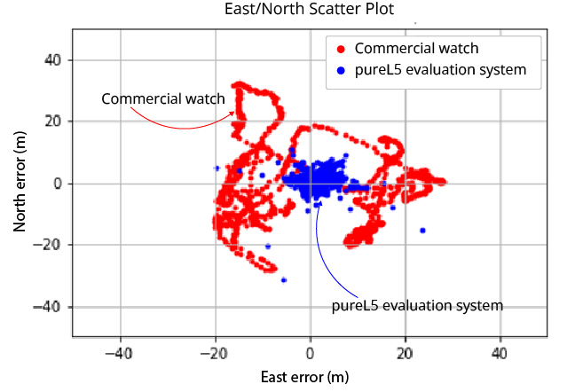
OneNav’s pureL5 more accurate in urban testing without sensor augmentation
Image: OneNav
OneNav is sharing side-by-side test results comparing its pureL5 GNSS receiver customer evaluation system to a leading Android smartwatch.
OneNav is a Silicon Valley, California-based technology company designed to power high-performance positioning for location-dependent mobile services.
In a challenging urban environment, oneNav averaged six times better accuracy than the smartwatch. Both units used commercial-wearable antennas for testing. While the oneNav system used only GNSS measurements, the smartwatch GNSS results were augmented by inertial sensors.
At the 95th percentile, the pureL5 unit reported 8-meter accuracy compared to nearly 29-meter accuracy for the smartwatch; pureL5 accuracy includes artificial intelligence/machine learning algorithms that improve the system over time.
“The L5 signal is more accurate and reliable than L1, it has higher power and wider bandwidth, and it is less jammable,” said Steve Poizner, co-founder and CEO of oneNav. “We looked at where the market is heading, with the wearables and tracking device markets exploding and the demand for higher accuracy increasing, and we asked, ‘Why keep two bands/two RF chains/two antennas when you can get superior performance with just L5?’”
The oneNav team comprises top GNSS experts from Qualcomm, Apple, Intel, SnapTrack, SiRF, Trimble and eRide who have decades of GNSS and mobile industry experience. The team has expertise in GNSS system architecture, multipath mitigation, signal processing, ASIC design and AI/machine learning, and collectively has filed more than 300 career GNSS patents.
Investors include Google Ventures, Norwest Venture Partners and GSR Ventures.
As we bid farewell to the last GPS-IIA satellite and read of delays to both the launch schedule for GPS III satellites and roll-out of the OCX program, we are mindful of the need to maintain GPS as the “Gold Standard” in GNSS.
Certainly, new signals, enhanced resilience and expanded capabilities are offered by the modernized GPS playbook. Delays relative to both the BeiDou and Galileo constellations could seriously impact the position of GPS on the medals podium — maybe not in the longer term, but certainly in the coming few years.
This may have a secondary impact on the receiver market, shifting focus away from GPS to more capable signals in the near term. Once GPS has caught up, receiver manufacturers may choose to retain the technology that they developed to capitalize on BeiDou and Galileo signals, rather than developing their legacy GPS capabilities.
GPS L2C is currently “pre-operational,” transmitted by slightly more than half the existing mixed-generation satellite fleet and waiting for OCX support. As of Feb. 20, a realistic estimate for operational capability of GPS L2C is now 2023.
GPS L5 is also pre-operational, transmitted by slightly less than half of the GPS satellites and waiting for OCX support. As of Feb. 20, a realistic estimate for GPS L5 is 2027.
The forecast for GPS L1C operational capability is the late 2020s. This is intended to be the signal that offers international interoperability with the current interoperability signals offered by existing BeiDou and Galileo satellites.
Delays to the implementation of GPS L1C may mean that GPS misses the interoperability boat entirely. During the delay, new interoperability capability with even more robust signals could be devised and lofted aboard Galileo, BeiDou and GLONASS satellites. By then, other countries could also develop their own constellations, possibly regional or even global systems.
Potentially, GPS could be left behind as other nations discuss non-GPS internationally interoperable signals on yet-to-be launched satellites. This may have a profound impact on SBAS, too. Differential corrections provided by the Japanese MSAS, Russian SDCM and European EGNOS SBAS systems might evolve to support “beyond L1C” interoperability signals. Aircraft landings at world airports could mandate the use of corrections to these new signals. This might mean that U.S. receiver manufacturers could be frozen out, or will have to incorporate these new interoperable signal standards.
GPS Block III satellites along with OCX offer improved signals, capabilities and resilience, but the satellites need to be flying, OCX needs to be operational and receivers need to be in the hands of the users. Sooner rather than later is a must for Gold-Standard GPS.
Paul Crampton is a senior systems engineer at Spirent Federal Systems with more than 30 years of GPS experience.
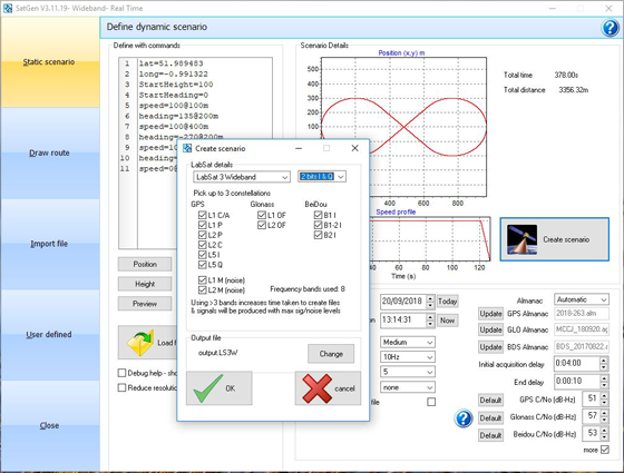
The software now includes simulation of the L2C and L5 GPS signals, meaning that SatGen V3 can be used to create one scenario containing all 13 signals from GPS, GLONASS and BeiDou constellations, the company said.
The simulation accuracy has also been improved — for example, most of the GPS pseudorange residuals are now sub-meter.
Signals that can be simulated simultaneously with SatGen V3 Wideband include:
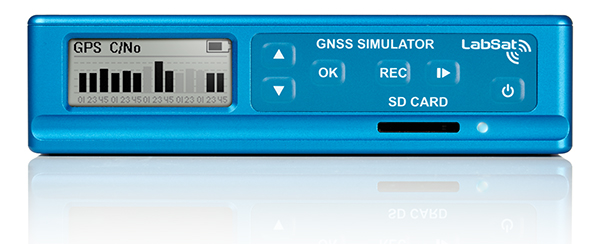
SatGen software allows users to create a GNSS RF I&Q or IF data file that can be replayed on a LabSat, which is based on a user-generated trajectory file. This allows simulators of almost any kind of test, at a set time and date, anywhere in the world.
SatGen complements the LabSat range of GNSS simulators, and is available in single, dual, triple and multi-frequency/multi-constellation versions.
LabSat showcased the upgrade at the ION GNSS+ conference, which took place Sept. 24-28 in Miami.
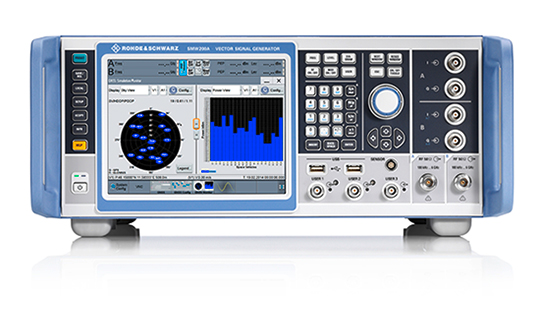
Rohde & Schwarz has added GPS L5 and Galileo E5 simulation capabilities to its R&S SMW200A GNSS simulator.
The R&S SMW200A GNSS simulator is designed for efficient test and characterization of multi-constellation and multi-frequency GNSS receivers. With its additional simulation capabilities for GPS L5 and Galileo E5, the R&S SMW200A enables generation of complex and highly realistic test scenarios with up to 144 channels in the GNSS frequency bands L1, L2 and L5, the company said.
In addition to GPS (L1/L2/L5), GLONASS (L1/L2), Galileo (E1/E5) and BeiDou (L1/L2), the R&S SMW200A also supports signal generation for QZSS and SBAS on L1. The available channels can be routed to up to four RF outputs, so that even multi-antenna systems can be tested.
Apart from its new GNSS simulation capabilities, the R&S SMW200A can generate complex coexistence and interference scenarios with multiple interferers. GNSS signals, noise and all interference signals are generated directly in the instrument. Additional signal sources for external generation of interference signals are not required, resulting in small, compact and simple test setups.
Launched in 2017, the R&S SMW200A can be turned into a high-end GNSS simulator and is able to internally simulate complex interference environments in parallel with GNSS signals.
An increasing number of GNSS receivers are capable of receiving signals on multiple different frequencies, such as L1, L2 and L5. Although this multi-frequency capability, as well as having to process signals from diverse navigation systems such as GPS, GLONASS, Galileo or BeiDou, make the receiver design more complex, they ensure a better quality of service for the end user.
According to the company, multi-frequency and multi-constellation processing not only improves positioning accuracy, service availability and robustness, it also makes the positioning process less vulnerable to interference, jamming or spoofing attacks.
The R&S SMW200A with its new GNSS simulation capabilities will be showcased at the ION GNSS+ 2018 trade show in Miami.
A Preliminary Analysis of SVN49’s Demonstration Signal
By Michael Meurer, Stefan Erker, Steffen Thölert, Oliver Montenbruck, André Hauschild, and Richard B. Langley
Great excitement surrounds the activation of a new transmitter from a satellite — an occasion dubbed first light. Research groups around the globe joined the GPS Wing in monitoring and analyzing the first L5 signals from space. We describe the equipment and procedures used to capture and analyze SVN49’s signals and give an assessment of their characteristics.
INNOVATION INSIGHTS by Richard Langley
ON APRIL 10, a new type of radio signal was transmitted from space. I am referring, of course, to the L5 demonstration signal from the Block IIR-M satellite SVN49, launched on March 24. The L5 signal, the second of two new civil GPS signals, will be standard on the next generation of GPS satellites — the Block IIFs — and its frequency band was duly registered with the International Telecommunication Union (ITU) back in 2002. But satellite operators only have seven years after filing a frequency application to start transmitting signals from the designated orbit, and delays in launching the first Block IIF satellite meant that GPS could lose the allocation. The GPS Wing and its contractors determined that the best way to secure the L5 frequency was to add an L5 demonstration payload to one of the remaining modernized Block IIR satellites. And so SVN49 made history with the inaugural broadcast of L5 with just a few months to spare before the clock ran out on the ITU filing.
Great excitement always surrounds the first photons captured by a new telescope or other detectors of electromagnetic signals. Or when a transmitter is activated for the first time. Just as we do for the dawning of a new day, we call this occasion first light. Research groups around the globe joined the GPS Wing in monitoring and analyzing the first L5 signals from space, including a group of scientists and engineers from Germany and Canada. This month the group describes the equipment and procedures used to capture and analyze SVN49’s signals and gives an assessment of their characteristics.
“Innovation” features discussions about advances in GPS technology and applications as well as fundamentals of GPS positioning. The column is coordinated by Richard Langley of the Department of Geodesy and Geomatics Engineering, University of New Brunswick. To contact him, see “Contributing Editors.”
A key feature of GPS modernization is the addition of the L5 civil signal to the suite of signals transmitted by the satellites. The introduction of such a signal on a different carrier frequency than that used by the legacy L1 GPS signal was proposed in the 1995 reports by the U.S. National Research Council and the National Academy of Public Administration on the future of GPS. The reports argued that an unencrypted signal on a second frequency would offer civil users the benefit of ionospheric delay correction, wide-lane carrier-phase ambiguity resolution, improved interference rejection, and faster accuracy recovery in multipath environments.
Studies showed that it would be possible to add a civil signal on the L2 frequency without compromising the military signal. High-precision (and accuracy) civil users had been using the L2 frequency — initially designated for military use only — ever since the first GPS satellites were launched, and through clever (though suboptimum) tracking techniques even after the L2 signals were encrypted. An unencrypted signal on L2 would bring these users a more robust signal as well as affording all civil users the benefits of a second frequency. But unlike the L1 signal, the L2 signal is situated in a part of the radio spectrum not officially protected from interference by other users of the spectrum. So such a second civil signal could not be used for safety-of-life applications such as navigating aircraft.
So, in Vice President Al Gore’s statement of March 30, 1998, on the enhancement of GPS for civil users, the decision to deploy two new civil signals was announced: the civil signal on L2, now known as L2C, and a signal on a new frequency, which became known as L5. Some readers might wonder why this new signal was not designated L3 or L4. Those designations had already been assigned to signals associated with other payloads on the GPS satellites.
Although the Gore announcement proposed to introduce both of the new civil signals with the launch of the Block IIF satellites, the addition of the L2C signal to the legacy signals was deemed a relatively straightforward task and the decision was made to modify the last eight Block IIR satellites for the provision of L2C. The first modernized Block IIR satellite was launched on September 26, 2005, and seven of these satellites are now in orbit.
The frequency selected for the L5 signal, 1176.45 MHz, is in a protected aeronautical radionavigation services (ARNS) band. This frequency, as with frequencies used by all satellite operators, had to be coordinated with the International Telecommunication Union-Radiocommunication Sector (ITU-R). The ITU-R registers frequencies essentially on a first-come, first-served basis, but a user must actually transmit signals on the assigned frequency from the designated satellite orbit type within seven years from the date of filing with ITU-R. This meant that L5 signals had to be transmitted before August 26, 2009, to avoid the potential claim of the frequency by a different country. A decision was made to modify an existing Block IIR-M satellite to carry an L5 demonstration payload. The L5 demo payload, which was developed by Lockheed Martin and its subcontractors, was added to space vehicle number (SVN) 49. SVN49 was launched on March 24, 2009, the seventh modernized Block IIR satellite to be placed in orbit. Also known as PRN1, from the primary pseudorandom noise (PRN) codes assigned to the satellite, the satellite began L5 transmissions on April 10, at 11:58 UTC, and so satisfied the ITU-R filing requirement with a few months to spare.
The L5 Signal Structure
The structure of the future full L5 signal will differ significantly from the legacy L1 signal or even the modernized L2C signal. It is fully described in the Navstar GPS L5 interface document, IS-GPS-705. We present just a brief overview of the signal here.
Two-Component Signal. The full L5 signal will offer two signal components: one with and one without a superimposed navigation data message. The two signal components — in-phase (I) and quadrature (Q) — have equal power. Both will have a minimum received power of –157 dBW. Each component is modulated with a different, but synchronized, L5 PRN code. The in-phase component (the I- or data channel) is further modulated with a 100-symbol per second (sps) symbol stream carrying the navigation message data, and the quadrature component (the Q- or data-free channel, also called the pilot channel) is modulated only with a PRN code. Different, nearly orthogonal PRN codes (referred to as I5 and Q5) are used in the two components to prevent tracking biases by making each component completely independent of the other, except for the underlying carrier phase.
Another novel aspect of the L5 signal design is the use of Neuman-Hoffman (NH) synchronization codes.
Code Structure. As previously mentioned, the I5 and Q5 channels are modulated with different PRN codes. These codes differ significantly from the C/A-, P-, and L2C-codes used on L1 and L2 both in length and chipping rate.
The natural code chipping-rate frequency of 10.23 MHz as provided by the SV atomic frequency standards satisfies a number of requirements for a modernized signal within the bandwidth constraints — increased bandwidth efficiency, improved signal accuracy, immunity to waveform distortion, and improved rejection of narrowband interference. The bandwidth constraints include rejection of out-of-band interference. Accordingly, a 10.23 megachip per second (Mcps) chipping rate, 10 times that of the C/A- and L2C-codes, was adopted for the L5 PRN codes.
Improved Cross-Correlation. There is a trade off between code period and the capability to do direct acquisition. A longer code period provides better cross-correlation properties, but takes longer to search. However, one can speed up an acquisition to some extent with lower code cross-correlation levels.
The L1 C/A-code period is 1023 chips, or 1 millisecond. The desire to maintain that epoch rate of 1 kHz with the 10.23 Mcps chipping rate results in a code period of 10,230 chips. For both the I5 and Q5 ranging codes, the 1-millisecond sequences are the modulo-2 sum of two sub-sequences referred to as XA and XB with lengths of 8,190 and 8,191 chips, respectively. The same XA sequence is used for both I5 and IQ, whereas the XB sequence for I5 is different from that for Q5. The XB sequences are selectively advanced to produce different 1-millisecond-long code sequences. In this way, a large number of unique codes can be generated. Thirty-seven primary code pairs have been designated, of which 32 are reserved for use by GPS satellites (PRNs 1–32). An additional 173 pairs have been defined (PRNs 38–210). PRN sequences 38 through 63 are reserved for satellites.
Demo Signal Verification
The L5 signal transmitted by SVN49 contains only the dataless quadrature component modulated with the PRN63 Q5 sequence. Furthermore, the transmitted L5 signal power and the satellite antenna radiation pattern are different from those expected for the L5 signals to be transmitted by the Block IIF satellites as described in the L5 interface specification.
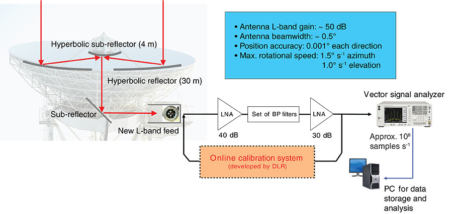
Over the past few weeks, the German Aerospace Center (Deutsches Zentrum für Luft- und Raumfahrt or DLR) has monitored SVN49 using its GNSS verification and analysis facility. The core element of the facility is a 30-meter dish antenna at Weilheim, near Munich, Germany, and is shown in FIGURE 1. The antenna, which is based on a shaped Cassegrain system, has a 30-meter-diameter parabolic reflector and a hyperbolic sub-reflector with a diameter of 4 meters. The L-Band gain of this high-gain antenna is around 50 dB, with a beam width of less than 0.5°. The position accuracy in both azimuth and elevation directions is 0.001°. The antenna’s maximum slewing speeds are 1.5° per second in azimuth and 1.0° per second in elevation angle, allowing it to easily track MEO satellites.
FIGURE 1. GNSS verification and analysis facility with 30-meter high-gain antenna at Weilheim, Germany.
In September 2005, DLR’s Institute of Communications and Navigation established an independent monitoring station for the analysis of GNSS signals using this powerful instrument. For the new challenge, the antenna was adapted to the requirements in the navigation field. A newly developed broadband circularly polarized feed and a new receiving chain including an online calibration system were installed at the antenna during preparations for the GIOVE-B in-orbit test campaign in the spring of 2008.
During this time, intensive work on the system calibration was performed using well-known signals from radio “stars” and EGNOS satellites for the antenna gain determination, and sophisticated calibration methods for the receiving system. The calibration provides an absolute measurement uncertainty significantly less than 1 dB.
Due to the distance of the antenna location from the institute at Oberpfaffenhofen (around 40 kilometers), it was necessary to perform all measurement and calibration procedures during the measurement campaigns under remote control. A software tool was developed that can control any component of the setup remotely. In addition, this tool is able to perform a completely autonomous operation of the whole system by a pre-definable sequence over any period of time. Additional details about the GNSS verification and analysis facility and the calibration techniques used can be found in the literature cited in Further Reading.
A detailed signal-in-space (SIS) analysis of the new L5 signal transmitted by SVN49 was conducted by recording several passes with the GNSS verification and analysis facility. A high elevation-angle transit of SVN49 every night allows a long observation time for each satellite pass. To ensure precise tracking of the satellite with the high-gain antenna, we used the latest two-line element sets from the U.S. Air Force Space Command.
The first signals transmitted by the satellite on the L5 frequency were captured during the pass on April 10. Compared to later measurements, the power of the L5 payload signal was measured with a lower output level on this first pass. This points to a power “fade in,” which is a common procedure in commissioning a new satellite payload. A controlled and slow heating of the payload elements avoids possible damage caused by the out-gassing of the power amplifiers, for example.
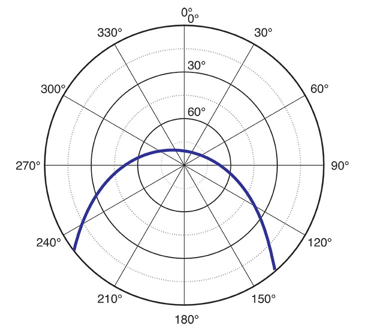
The SIS analyses that we performed using the high-gain antenna will be described for one example satellite pass recorded on April 29. During this pass, the satellite reached an elevation angle of around 80° and was visible for about seven hours (see FIGURE 2). A set of spectral snapshots as well as time sample records for the L1, L2, and L5 signals were processed and adjusted with the corresponding calibration values during a post-processing stage.
FIGURE 2. Skyplot of SVN49 pass at Weilheim, Germany, on April 29, 2009.
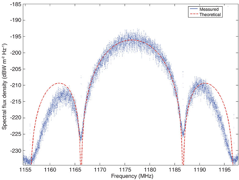
Time and Frequency. A first view of the captured spectrum snapshot in FIGURE 3 shows the L5 signal and its typical binary phase-shift-keyed (BPSK) spectral shape. The signal is significantly band limited by the used front-end filters of the satellite’s L5 payload. This ensures the required spectral separation from the adjacent L2 signal of the satellite, as the L5 signal must not interfere with the operational L2 frequency. Overlaying the theoretical spectral mask of the L5 BPSK signal, we note a slight asymmetry of the spectral shape. The two side lobes differ around 2.5 dB in their peak power level (see Figure 3). Spectral asymmetries of that kind typically result from frequency selectivity in the RF transmitter chains in satellite payloads, including the amplifiers and antennas.
FIGURE 3. L5 spectrum plot from data recorded on April 29.
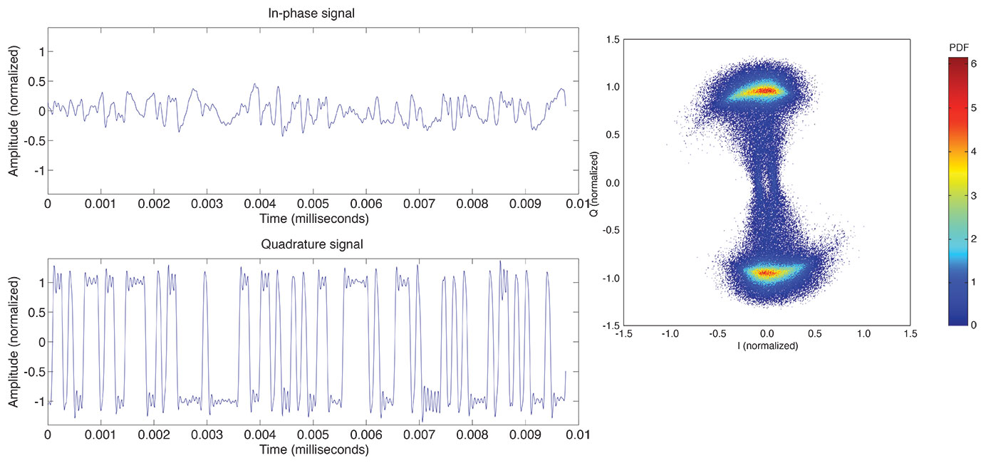
FIGURE 4 shows a temporal snapshot of the L5 signal after wiping off the Doppler frequency shift due to satellite orbital motion. Figure 4 (left) depicts a snapshot of 10 microseconds for the I and Q channels. It can be seen, that in compliance with the requirements of the L5 signal explained in the introduction of this article, the signal is a bi-level signal with a chipping rate of 10.23 Mcps. Plotting the normalized histogram of the L5 signal, one obtains the normalized I/Q probability density function (PDF) diagram of the L5 signal shown in Figure 4 (right). The constellation diagram shows a remaining deformation of the Q component after Doppler removal. Although the L5 signal transmitted by the test payload only contains the dataless Q5 component, a non-negligible contribution can be seen in the I channel. This slight distortion may stem from a nonlinear and frequency-dependent amplification of the Q baseband signal leading to crosstalk between the Q and I channels.
FIGURE 4. (left) L5 I and Q time samples; (right) L5 I/Q probability density function (PDF).
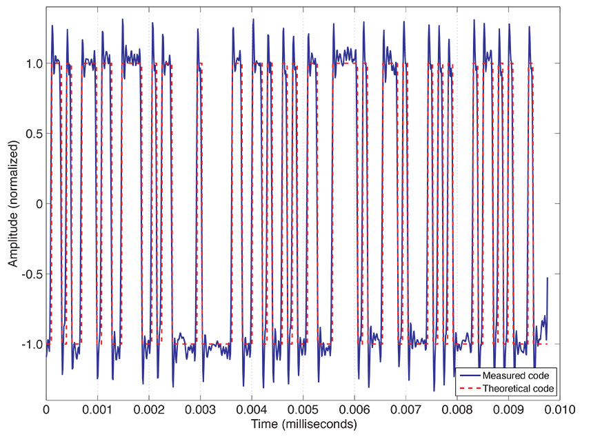
Signal Code Sequence. With the use of the high-gain antenna, it is possible to look in detail at the transmitted L5 code chips. The signal is raised high above the noise floor and, after Doppler wipe off, allows us to compare the received code sequence with the theoretical code sequence for the PRN63 Q channel. FIGURE 5 shows an example for the first 10 microseconds of the code — both for the measured L5 signal and the expected theoretical code. The analysis performed also for several full code periods shows that the demo payload’s Q5 code structure is in full compliance with the “theoretical” code described in the official signal interface document.
FIGURE 5. Comparison of measured and theoretical code sequences.
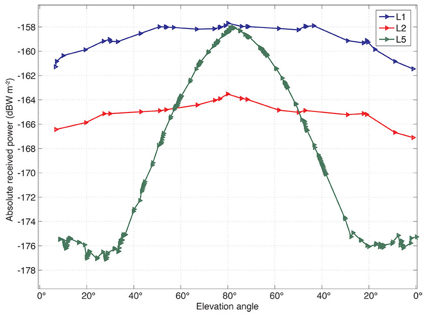
Power of Received Signals. The GNSS verification and analysis facility is fully calibrated, allowing highly accurate absolute measurements of GNSS signal power levels. We have used the system to evaluate the SVN49 signal power levels as received on the ground. FIGURE 6 shows the different signals transmitted in the L1, L2, and L5 frequency bands in terms of the received power per square meter versus elevation angle of the SV during its pass. It can be seen that there is a significant elevation-angle dependency of the L5 received power (about 18 dB between low and high elevation angles) compared to L1 and L2 (with a variation of about 3 dB). In this measurement, the combined power of the I and Q channels is plotted for the signals. So this means that the L1 and L2 signal measurements include the power of the C/A-, P(Y)-, and M-codes. Such a strong elevation-angle dependency is not typical of signals radiated by GPS satellites. However, the L5 signal is radiated using the legacy L1/L2 Block IIR-M satellite antenna, which is to the authors’ knowledge not optimized for the L5 frequency.
FIGURE 6. Absolute received power for SVN49 L1, L2, and L5 signals on April 29, 2009.
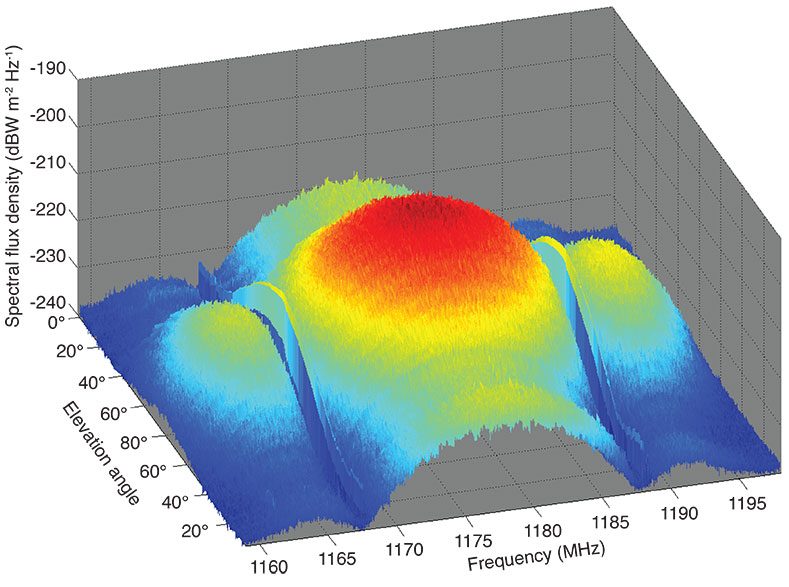
In the spectrogram plot of FIGURE 7, which was generated by plotting all recorded L5 spectra versus elevation angle, the impact of this elevation-angle dependency of the received power can be detailed for the complete frequency range. The side lobes of the BPSK signal are only clearly visible in the spectrogram at higher elevation angles.
FIGURE 7. Spectrogram for L5 signal received on April 29, 2009.
Signal Tracking
In parallel with the detailed signal validation using the high-gain antenna and vector signal analyzer, an effort has also been made to track the new GPS L5 signal using conventional correlating GNSS receivers. Given the relevance of L5/E5 signals for future aeronautical applications and the ongoing transmission of such signals from the GIOVE satellites, a growing number of commercial receiver manufacturers have announced receivers supporting this frequency band. However, due to the special nature of the SVN49 test signal (pilot only, with different PRN code designations on L1 and L5) some modifications to receiver software are required to properly track the first GPS L5 signal. In particular, the use of different PRN code designations employed for L1/L2 (PRN1) and L5 (PRN63) is clearly non-standard and requires suitably adapted receiver software, which was provided by the makers of the two receiver types we selected for our test campaign.
Receiver type N is a highly configurable test receiver for L1 and L5/E5a signals developed as part of the Galileo program. It offers a total of 16 tracking channels, which are implemented in a field-programmable gate array and can thus be flexibly adapted for tracking of civil GPS, satellite-based augmentation systems, and the GIOVE-A and -B signals in their respective frequency bands. Receiver type J, in contrast, represents the latest generation of geodetic grade multi-constellation receivers. It uses an advanced application-specific integrated circuit with 216 tracking channels supporting all types of non-military navigation signals in the L1/E1, L2, and L5/E5a bands. Both receivers have been used for some time prior to the launch of SVN49 to track GPS and GIOVE satellites from stations at the University of New Brunswick (UNB) in Canada and at DLR in Germany.
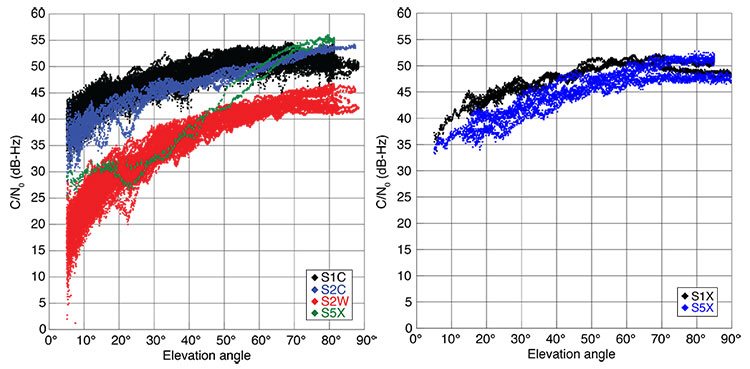
The first measurements of GPS L5 were successfully collected on April 10 with a type N receiver at UNB. While these measurements confirmed the capability to properly track SVN49 in the L5 band, they already revealed a distinct aspect of the GPS L5 test signal that potential users must be aware of. The signal is much weaker at low elevation angles than the L1 signal. Normal carrier-to-noise-density ratios (C/N0) are only achieved at elevation angles of about 60° and higher. On the other hand, the measured C/N0 near zenith may even outperform that of L1 and L2 tracking with sufficient L5 antenna gain. For illustration, FIGURE 8 compares the measured C/N0 values of GPS and GIOVE-A/B signals as obtained with receiver type J and a geodetic antenna at DLR, Oberpfaffenhofen.
FIGURE 8. Comparison of the relative signals strength (expressed as carrier-to-noise-density ratio, C/N0) for GPS (left) and GIOVE-A/B signals (right). The signals are described by their respective RINEX 3.00 data format identifiers, which reflect the type of measurement (S=signal strength), the frequency band (1=L1/E1, 2=L2, 5=L5/E5a) and the signal attribute (C=C/A or L2C, W=P(Y) semicodeless, X=pilot and data).
While not officially confirmed so far, the abnormal variation of the L5 signal strength can best be attributed to a non-standard gain pattern of the satellite transmitter antenna. Apparently, the existing Block IIR-M satellite antenna “farm” has been used to transmit the L5 signal, which results in more directivity than that of the L1 and L2 signals. This results in a weaker signal for receivers further away from the antenna boresight axis, or, equivalently, stations observing the satellite at low elevation angles. Even though the achieved C/N0 of the GPS L5 test signal is lower than that of the direct L1 C/A-code and L2 L2C-code tracking for most of a tracking arc, the signal quality still exceeds that of the semicodeless P(Y)-code tracking on L1 and L2. This makes the signal a valuable basis for experimentation in aviation applications or triple-frequency processing.
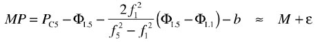
To assess the quality of the raw GPS measurements, we made use of the so-called multipath combination of pseudorange and carrier-phase measurements:
The combination is essentially the difference between the pseudorange (PC5) and carrier-phase measurement (ΦL5) on the L5 frequency, and therefore measures the sum of the pseudorange multipath (M) and noise (ε). Due to the opposite sign of ionospheric path delays on code and phase measurements, an ionospheric correction is used in the multipath combination, which requires phase measurements on a second frequency (in this case L1). The individual carrier-phase biases are, furthermore, aggregated into a common bias (b). Other than in a traditional zero-baseline test, the multipath combination neither requires a second receiver nor a second satellite transmitting the same signal in space. It is therefore best suited for studying the tracking performance of the new GPS L5 test signal.
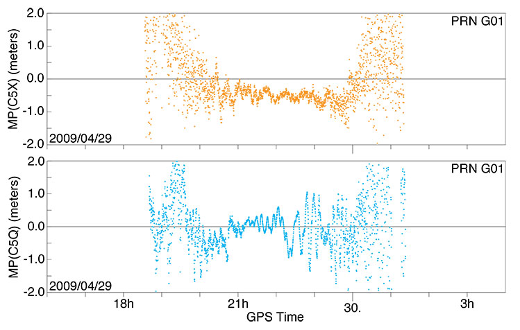
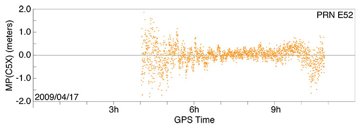
Results for receiver types N and J obtained at DLR, Oberpfaffenhofen, are shown in FIGURE 9 for a sample, high-elevation angle tracking pass. Despite obvious differences that can be related to the specific multipath environment and code-smoothing strategies for the two receivers, a high quality is obtained in both cases. For the central three-hour interval, during which the L5 signal was received with normal signal strength, the achieved tracking accuracy clearly outperforms that of the L1 C/A-code signal for the given receivers. For further comparison, FIGURE 10 shows sample results of GIOVE-B E5a tracking with receiver type J. Again, the GPS L5 signal at medium- to high-elevation angles is fully competitive and a notable degradation is only evident when the signal strength is well below the values to be expected in the future operational system.
FIGURE 9. Pseudorange multipath and receiver noise of SVN49 (PRN G01) L5 tracking for a selected pass over Oberpfaffenhofen, Germany, on April 29-30, 2009. Top: receiver type J with geodetic antenna. Bottom: receiver type N with a Galileo antenna. The satellite exceeded an elevation angle of 50° between 20:30 and 23:30 with a peak elevation angle of 80° near 22:00.FIGURE 10. Pseudorange multipath and receiver noise of GIOVE-B L5 tracking for a high pass over Oberpfaffenhofen, Germany, on April 17, 2009, using receiver type J.
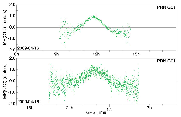
Legacy Signal Anomaly. While the GPS L5 signal transmission by SVN49 is clearly designated as experimental, the legacy signals (that is, the C/A- and P(Y)-code on L1 as well as L2C- and P(Y)-code on L2) were expected to achieve the same level of performance as observed on other satellites of the existing constellation. This is not the case, however, in the L1 band where both the C/A-code measurements and the semicodeless P(Y)-code pseudoranges exhibit a systematic, elevation-angle-dependent bias. This bias is not specific to any of our test receivers and can be similarly observed in heritage receivers employed at the stations of the International GNSS Service (IGS). As an example, FIGURE 11 illustrates the variation of the C/A-code error for high-elevation angle passes of SVN49 over western Canada and Germany. The bias varies between approximately -0.5 meters near the horizon and 1meter near zenith.
The cause of the bias is unclear but resides apparently in the design of the transmitter antenna or signal generation chain. It is exclusively seen on SVN49 and not on other GPS (or GIOVE) satellites, which excludes a possible problem of the receiver antenna or environment. Furthermore, data collected at UNB using the UNBJ IGS station a few days after launch clearly demonstrate that the elevation-angle-dependent L1 bias existed well before L5 signal activation and therefore might not be related to the signal generator. It is unclear to what extent the L1 signal bias can be corrected on the spacecraft and how it will affect the declaration of SVN49 as a fully healthy satellite.
FIGURE 11. Pseudorange errors of SVN49 L1 C/A code tracking for high-elevation-angle passes using a type A receiver at IGS station DRAO in Penticton, Canada (top), and a type J receiver at Oberpfaffenhofen (bottom). The satellite achieved peak elevation angles of about 70° and 80°, respectively, at the two sites.
Conclusions
Tracking and analysis of SVN49’s L5 signal using both the 30-meter dish and code-correlating receivers reveals that it possesses improved signal characteristics with respect to the legacy signals, in particular with regard to its bandwidth, and therefore will allow even more accurate and reliable positioning when the signal is deployed on the future Block IIF constellation.
Acknowledgments
We thank NovAtel and JAVAD GNSS for supplying special firmware, Sébastien Carcanague at UNB, and DLR colleagues at Weilheim for their help. The L5 signal description comes from the Innovation article by A.J. Van Dierendonck and C. Hegarty, September 2000 issue of GPS World.
Manufacturers
Receiver N is the NovAtel (www.novatel.com) EuroPak-15a. Receiver J is the JAVAD GNSS (www.javad.com) Triumph Delta-G2T. Receiver A is an Allen Osborne Associates (AOA) Benchmark ACT (www.itt.com). Space Engineering (www.space.it) Galileo Experimental Sensor Station antenna, Trimble (www.trimble.com) Zephyr Geodetic II antenna, and AOA D/MT antennas were used.
MICHAEL MEURER received a Ph.D. in electrical engineering from the University of Kaiserslautern, Germany. He is director of the Department for Navigation in the Institute for Communications and Navigation of the German Aerospace Center (DLR).
STEFAN ERKER received his diploma degree in information technology from the Technical University of Kaiserslautern and works at DLR’s Institute for Communications and Navigation.
STEFFEN THÖLERT received his diploma degree in electrical engineering from the University of Magdeburg and works at DLR.
OLIVER MONTENBRUCK works at DLR’s German Space Operations Center, Oberpfaffenhofen, where he is head of the GPS Technology and Navigation Group. He holds a Dr.rer.nat degree in physics.
ANDRÉ HAUSCHILD received his diploma degree in mechanical engineering from the Technical University of Braunschweig, Germany, and is a Ph.D. candidate at DLR’s German Space Operations Center.
Further Reading
L5 Signal Details
Interface Specification, IS-GPS-705 (IRN-705-003), Navstar GPS Space Segment/User Segment L5 Interfaces, ARINC Engineering Services, LLC, El Segundo, California, September 22, 2005.
“The New L5 Civil GPS Signal” by A.J. Van Dierendonck and C. Hegarty in GPS World, Vol. 11, No.9, September 2000, pp. 64–72.
DLR’s GNSS Verification and Analysis Facility
“GNSS Signal Verification: Spectral and Temporal Analysis of GIOVE B and BEIDOU Signals” by S. Thölert, S. Erker, M. Cuntz, M. Meurer, U. Grunert, and J. Furthner, presented at Navitec 2008, the 4th ESA Workshop on Satellite Navigation User Equipment Technologies, Noordwijk, The Netherlands, December 10–12, 2008.
“GNSS Signal Verification with a High Gain Antenna – Calibration Strategies and High Quality Signal Assessment” by S. Thölert, S. Erker, and M. Meurer in Proceedings of ITM 2009, the 2009 International Technical Meeting of The Institute of Navigation, Anaheim, California, January 26–28, 2009, pp. 289-300.
Nonlinearities in Microwave Signal Components
“Frequency-independent and Frequency Dependent Nonlinear Models of TWT Amplifiers” by A. Saleh in IEEE Transactions on Communications, Vol. 29, November 1981, pp. 1715–1720.
“Analysis of GIOVE-A L1-Signals” by S. Graf and C. Günther in Proceedings of ION GNSS 2006, the 19th International Technical Meeting of the Satellite Division of The Institute of Navigation, Fort Worth, Texas, September 26-29, 2006, pp. 1560–1566.
Commercial GNSS Receivers Used for L5 Signal Acquisition
“Triumph Technology” by J. Ashjaee presented at the 5th Allsat Open Conference, Hannover, Germany, June 19, 2008.
“A Dual-frequency L1/E5a Galileo Test Receiver” by N. Gerein, M. Olynik, M. Clayton, J. Auld, and T. Murfin in Proceedings of the European Navigation Conference – GNSS 2005, Munich, Germany, July 19-22, 2005.
The Multipath Observable
“TEQC: The Multi-Purpose Toolkit for GPS/GLONASS Data” by L.H. Estey and C.M. Meertens in GPSSolutions, Vol. 3, No. 1, 1999, pp. 42–49.
1995 Reports on the Future of GPS
The Global Positioning System: Charting the Future: Charting the Future by a panel of the National Academy of Public Administration and by a committee of the National Research Council, National Academy of Public Administration, Washington, D.C., 1995, ISBN 0-9646874-1-0.
The Global Positioning System: A Shared National Asset, Recommendations for Technical Improvements and Enhancements by the National Research Council Committee on the Future of the Global Positioning System, National Academy Press, Washington, D.C., 1995, ISBN 0-309-05283-1.
The Seminal Article on the Benefits of Three GPS Signal Frequencies
“The Promise of a Third Frequency” by R.R. Hatch in GPS World, Vol. 7, No. 5, May 1996, pp. 55–58.