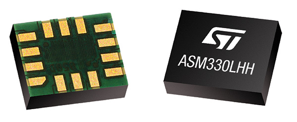
STMicroelectronics has introduced the automotive-grade ASM330LHH six-axis inertial sensor for super-high-resolution motion tracking in advanced vehicle navigation and telematics applications.
Photo: STMicroelectronics
Serving demands for continuous, accurate vehicle location to support automated services, the ASM330LHH lets advanced dead-reckoning algorithms calculate precise position from sensor data if satellite signals are blocked, such as in urban canyons, tunnels, covered roadways, parking garages or dense forests.
Its advanced, low-noise, temperature-stable design enables dependable telematics services such as e-tolling, tele-diagnostics and e-Call assistance. Precision inertial data in six axes also meets the needs of advanced automated-driving systems, the company said.
Automotive component manufacturer Magneti Marelli has selected the ASM330LHH for advanced telematics systems, to be fitted as original equipment by global automotive groups in upcoming vehicle ranges.
For the ASM330LHH, as with all its MEMS sensors, STMicroelectronics owns the entire manufacturing process, from designing the sensors, through wafer fabrication, packaging, test, calibration and supply. Full end-to-end control enables STMicroelectronics to create high-performing sensors and assure customers of a robust and responsive supply chain, with rigorous end-of-line quality screening, the company said.
“STMicroelectronics is the largest supplier of MEMS sensors for automotive non-safety applications, such as navigation and telematics,” said Andrea Onetti, Analog, MEMS and Sensors Group vice president at STMicroelectronics. “Our latest-generation inertial sensor, the automotive-grade ASM330LHH, enables precise positioning for safer, smarter driving.”
Engineering samples will be available for evaluation by the third quarter of 2018, and volume production will begin the following quarter.
Further technical information on the ASM330LHH
Temperature range up 105 degrees Celsius giving designers extra freedom to locate electronic controls in hot areas such as in smart antennas on the vehicle roof, or near the engine compartment.
Ultra low noise allows greater measurement resolution by minimizing integration errors when positioning is reliant on sensors only.
High linearity and built-in temperature compensation eliminate any need for external compensation algorithms over its operating range.
Lowest power consumption in class, with features for optimizing power management if battery usage becomes crucial.
Qualified according to AEC-Q100 automotive-grade robustness standard.
Built on STMicroelectronics’ proven, proprietary ThELMA MEMS process technology, which enables integration of both the three-axis accelerometer and three-axis angular-rate sensor (gyroscope) on the same silicon for optimum yield, quality, and reliability.
The electronic interface integrates the signal chain for both sensors on a single die using STMicroelectronics’ 130nm HCMOS9A technology.
Reference designs, as well as STMicroelectronics’ Teseo satellite-positioning modules and related software are available. The dead-reckoning algorithm included with the Teseo III GNSS-receiver chipset already supports the ASM330LHH to generate a high-accuracy output suitable for autonomous navigation.
Tiny, low-profile 3mm x 2.5mm x 0.83mm device for minimal impact on the size of any on-board module.
Packaged as a leadless Land Grid Array (LGA) device.
Qianxun Spatial Intelligence Inc., a high-precision positioning service provider, and u-blox are joining forces to deliver high-precision positioning solutions to the Chinese market.
By coordinating their product offerings, they seek to meet growing demand for increased positioning accuracy for mass-market applications. Some of the areas driving up demand for high-precision positioning services in China are internet of things (IoT) tracking devices such as those used on shared bikes, as well as automotive, UAV and robotic vehicle applications.
u‑blox is bringing to the partnership its high-precision GNSS receivers. Its u‑blox F9 multi-band positioning platform uses integrated real-time kinematic (RTK) technology to process the high-precision positioning correction data provided by Qianxun SI, delivering down to centimeter-level positioning accuracy for wide-ranging applications. It enables even faster and more robust performance by leveraging a greater variety of GNSS signals.
Two major advancements have enabled sub-meter-level positioning accuracy for mass-market applications. The first is modern GNSS correction services that constantly monitor GNSS signals to determine positioning errors caused, for example, by atmospheric distortions, and wirelessly transmit correction data to compensate for these errors to millions of GNSS devices. The second is a new generation of small, power-efficient, and affordable GNSS receivers that are able to use the correction data to achieve such high levels of accuracy.
Qianxun SI, a high-precision positioning service provider, has already laid the groundwork for the large-scale expansion of high-precision positioning in the IoT era, the company said. Based on BeiDou, which is compatible with GPS, GLONASS and Galileo, Qianxun SI’s high-precision positioning service is built on the nationwide ONE Network, composed of more than 2,000 Continuously Operating Reference Stations (CORS) and using proprietary algorithms. It offers vehicles and other applications a range of 24/7 high-precision positioning services in most regions of the country.
By the end of 2018, Qianxun SI’s dynamic centimeter-level service will cover the entire mainland of China, the company said.
“We are delighted to cooperate with u-blox to provide users with high-precision positioning solutions that are user friendly and affordable,” said Jinpei Chen, CEO of Qianxun SI. “I believe our high-precision positioning technology is a key enabler of IoT development, and the cooperation with u‑blox will accelerate the go-to-market process of the technology in an extensive range of industrial and automotive market applications.”.
“This collaboration is a genuine win-win for all involved in that it allows us to develop high-precision solutions that will foster innovation across markets,” said Thomas Seiler, CEO of u-blox. “Partnering with China’s leading GNSS correction service provider allows u-blox customers to bring cutting edge applications to the China market in the shortest possible time.”
NovAtel has introduced several new precision positioning solutions for space-constrained applications. With enhanced positioning accuracy in a compact form, the PwrPak7D, PwrPak7DE1 and OEM7600 are suitable for automotive, airborne and other smaller unmanned systems.
PwrPak7D and PwrPak7D-E1 are dual-antenna, multi-frequency enclosures, and the OEM7600 receiver board, plus NovAtel’s new Waypoint Inertial Explorer Express post-processing software are being showcased this week at AUVSI Xponential 2018.
Dual-Antenna, Multi-Frequency Enclosures
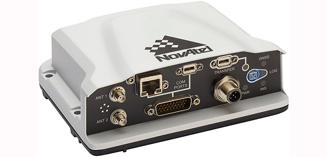
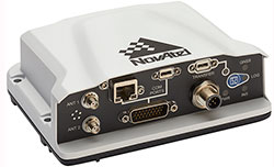
The new PwrPak7D enclosure. (Photo: NovAtel)
NovAtel’s new PwrPak7D and PwrPak7D-E1 enclosures provide space efficiency without sacrificing position accuracy and heading stability, even in stationary, slow-moving or hovering dynamics.
The PwrPak7D-E1 enclosure integrates an inertial measurement unit (IMU) with NovAtel’s OEM7720 dual-antenna receiver board to deliver GNSS and inertial navigation system (INS) capabilities.
When combined with NovAtel’s SPAN technology, positioning and attitude performance is optimized during extended GNSS outages.
Both the PwrPak7D and PwrPak7D-E1 include NovAtel’s Interference Toolkit with advanced interference detection
and mitigation features applicable to all stages of integration. A web user interface, accessible through Ethernet or
Wi-Fi, allows for quick and easy system configuration and control.
OEM7600 Receiver Board for Smaller Autonomous Systems
The OEM7600 receiver board. (Photo: NovAtel)
The OEM7600 receiver board features NovAtel’s high-performance positioning solutions in an extremely small form factor, wrapped with protective shielding to isolate emissions from surrounding electronics in confined spaces.
This new receiver integrates easily with NovAtel’s SPAN technology to optimize performance during extended GNSS outages.
The new OEM7600 will be commercially available this summer.
New Post-Processing Software for UAVs and Small Project Areas
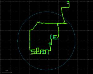
Inertial Explorer Xpress centroid circle. (Image: NovAtel)
Inertial Explorer Express provides the same core processing and utilities as the
Waypoint Inertial Explorer software for applications including unmanned aerial vehicles (UAVs) and smaller projects.
Inertial Explorer Express will produce centimeter-level position and attitude solutions compatible for lidar, camera and other sensor data with faster processing times and reduced complexity
“We are very excited to be introducing our new OEM7-based and Inertial Explorer solutions at Xponential 2018,” said Neil Gerein, director of product management at NovAtel. “These systems provide robust positioning and accuracy in a compact footprint for UAVs and smaller autonomous projects. An advanced range of software options, including NovAtel’s tightly coupled GNSS+Inertial SPAN technology and Interference Toolkit, provide assured positioning anywhere.”
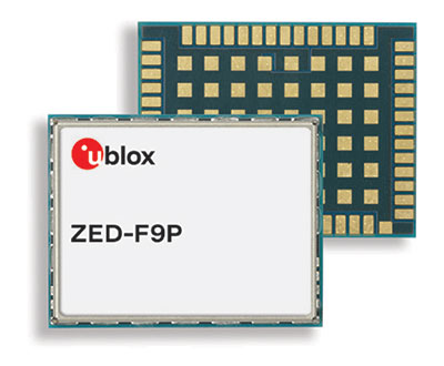
u-blox, a global provider of leading positioning and wireless communication technologies, has released the ZED-F9P multi-band GNSS module with integrated multi-band real-time kinematics (RTK) technology for machine control, ground robotic vehicles and high-precision unmanned aerial vehicles (UAV) applications.
The ZED‑F9P measures 22 x 17 x 2.4 millimeters and uses technology from the recently announced u‑blox F9 platform to deliver robust high-precision positioning performance in seconds.
The u-blox ZED-F9P is a mass market multi-band receiver that concurrently uses GNSS signals from all four GNSS constellations (GPS, GLONASS, Galileo and BeiDou). Combining GNSS signals from multiple frequency bands (L1/L2/L5) and RTK technology lets the ZED‑F9P achieve centimeter-level accuracy in seconds, the company said.
Receiving more satellite signals at any given time maximizes the availability of centimeter-level accuracy even in challenging environments such as in cities.
With its high update rate, the ZED‑F9P is suitable for highly dynamic applications such as UAVs. Featuring on-chip integration of advanced multi-band RTK algorithms, it requires no additional hardware or third-party RTK libraries. Ready to use on delivery and easy to integrate, it helps product developers quickly bring their ideas to the market.
ZED-F9P is fully geared to clearing the three main hurdles that have kept centimeter-level positioning accuracy from breaking into mass-market applications: cost, size and power consumption. Significantly smaller and more energy efficient than existing solutions, and as a cost efficient alternative, the ZED-F9P will enable new high-precision positioning applications for the mass market.
“The new ZED-F9P GNSS receiver builds on the success of our NEO-M8P high-precision GNSS module, but takes performance to another level by leveraging all the available GNSS signals,” said Mårten Ström, senior principal product management, product center positioning at u‑blox. “By making robust and affordable high-precision positioning technology more accessible, we hope to fuel innovation and enable a new generation of high-precision GNSS navigation applications.”
Engineering samples will be available at the end of July.
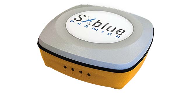
Geneq has launched the SXblue Premier GNSS receiver, which is available in a submetric version (GNSS) or centimetric version (real-time kinematic, RTK).
The new SXblue Premier GNSS receiver is equipped with the Pacific Crest Maxwell 6 Trimble technology with BD910 (GNSS version) and BD930 (RTK version) OEM boards, delivering 220 channels to acquire and track GNSS signals from all constellations in view. It makes effective use of GPS, GLONASS, Galileo, BeiDou, QZSS and SBAS signals for outstanding highly precise positioning.
The SXblue Premier is small and light weight, and rugged for field work. It is equipped with dual mode for Bluetooth V2.1 and Bluetooth V4.0, ensuring the unit’s wireless communication with any Android or Windows terminal. With its two models, the user will have large efficiency and flexibility on the field either with SBAS corrections or RTK reference networks.
In addition, SXblue Premier can be configured for Wi-Fi hotspots, allowing users to connect and access a web management platform. It also can be used as a data link, providing a quick connection to the internet to receive corrections from reference station (CORS) networks so that it can process RTK measurements.
With its internal memory using an 8-GB solid state disk, SXblue Premier provides enough storage space for field data collection or raw data recording for a high data sampling rate.
Multiple compatible software programs — including FieldGenius, Carlson, Collector for ArcGIS — will meet the users’ diverse need, making SXblue Premier more powerful and flexible.
u‑blox has rolled out the u-blox F9 technology platform, which was designed to deliver high-precision positioning solutions for mass market industrial and automotive applications.
The platform combines multi-band GNSS technology with dead-reckoning, high-precision algorithms, and compatibility with a variety of GNSS correction data services, to achieve precision down to the centimeter level.
u‑blox F9 paves the way for the next generation of high precision navigation, augmented reality, and unmanned vehicles, the company said.
The u-blox F9 platform will underpin the next wave of u‑blox positioning modules targeting mass market industrial and automotive applications. It uses GNSS signals in multiple frequency bands (L1/L2/L5) to correct positioning errors caused by the ionosphere and deliver fast time to first fix (Fast TTFF).
Its ability to receive signals from all GNSS constellations (GPS, GLONASS, Galileo, Beidou) further improves performance by increasing the number of satellites visible at any given time. Stand-alone u‑blox F9 solutions robustly achieve meter-level accuracy.
To achieve centimeter-level accuracy, u‑blox F9 offers optional on-chip real-time knematic (RTK) technology. In addition to offering an open interface to legacy GNSS correction service providers, it supports the main GNSS correction services, bringing RTK high-precision positioning to the mass market.
“High precision is the next frontier in positioning for mass markets, with countless applications in need of a robust and scalable high precision positioning solution. u‑blox F9 provides the hardware and integrated software components to address these needs,” said Daniel Ammann, executive director of positioning product development at u-blox.
Optimized for low power consumption, the u‑blox F9 platform sets a high standard for security with built-in jamming and spoofing detection systems that protect against intentional and unintentional interference. Dead-reckoning technology based on inertial sensors extends high-precision performance to otherwise challenging urban environments.
Automotive applications of the technology include lane-level navigation for head-up displays and vehicular infotainment systems as well as for vehicle-to-everything (V2X) communication, a prerequisite for highly automated and fully autonomous vehicles.
In the industrial realm, u‑blox F9 will enable mass adoption of commercial unmanned vehicle applications including drones and ground vehicles such as heavy trucks or robotic lawnmowers.
The u‑blox F9 platform’s technology will be showcased at Embedded World in Nuremberg, Germany from Feb. 27-March 1 at Booth #3-139. Product samples will be available later in the year.
For those who want high accuracy, but don’t need it full time, high-productivity dedicated professional solutions may not be cost-justified. In these cases, a “positioning as a service” subscription could offer a viable use model.
Achieving precision positioning with just a standard mobile device, a correction stream using the mobile device’s data connection and a high-accuracy positioning application produces a very low barrier to achieving high accuracy.
ByStuart Riley, Herbert Landau, Victor Gomez, Nataliya Mishukova, Will Lentz and Adam Clare, Trimble Inc.
We expect that for professional applications that need precision positions, a dedicated system that employs a custom GNSS chipset and purpose-built applications will continue to be the right solution. However, it becomes clear that the ubiquity of consumer mobile devices, with increasing computing power, ruggedness and an expanding feature set, presents fertile ground for new development of improved positioning systems that don’t have strict professional requirements.
A range of new use models and applications will be enabled by consumer mobile phones with technology that improves positioning performance. The goal of the work presented here is to assess what level of performance can be achieved by using proprietary PVT (position, velocity, time) engines utilizing GNSS measurements from the Android GNSS measurement application programming interface (API).
We first review GNSS measurement and positioning performance from a subset of the current Android phones/tablets currently on the market. Then we show the position performance achievable using precision engine with measurements from a dual-frequency GNSS chipset targeted for the cellular handset market. This class of device is expected to be integrated into consumer cellular devices on the market within the next 1 to 2 years.
Performance of Current Phones
We tested various devices including the Nexus 9 (which provides phase data) and various other Android devices that implement the new API. Most devices tested do not support phase data; of the few devices tested that do provide phase data, all except the Nexus 9 implement GNSS power duty cycling. This is a mode where the GNSS chipset is only active for a fraction of each second to reduce power consumption. This results in cycle slips each epoch, which makes carrier-phase processing for real-time kinematic (RTK) unusable.
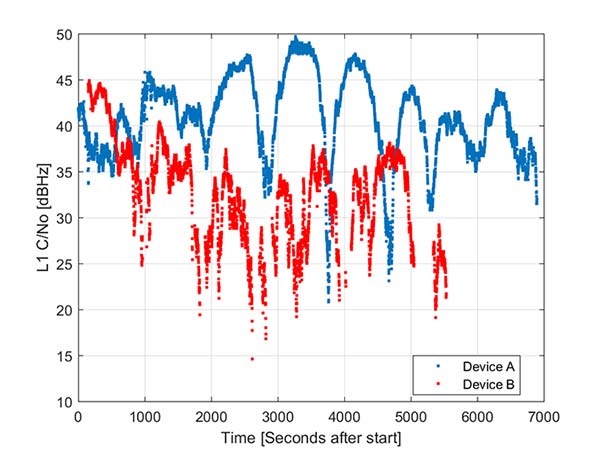
During the testing a wide range of performance across devices was observed. Figure 1 shows the C/NO for a high-elevation GPS satellite collected at the same time from two different Android models that implement the GNSS measurement API. The units were located in a clear environment less than a meter apart. Deep fades are present, most likely caused by deconstructive multipath.
Figure 1. Comparison of the C/NO from two different Android devices.
However, the devices show significantly different tracking performance: device B reports over 10 dB lower C/NO for much of the test and eventually stops reporting measurements. During our analysis, around six different Android devices have been tested; it isn’t clear whether the devices tested are typical over a broader population of device types.
Before attempting to position with observables from Android devices the measurement quality was analyzed. As only a subset of current devices that support the API provide phase information we wanted to evaluate both a phase-based RTK engine and a pseudorange/Doppler based code engine to determine what is possible from each class of device.
One of the devices tested was a Samsung S7 device. It provides pseudorange, Doppler and phase via the GNSS measurement API. However, the phone implements power duty cycling so after a short period of operation the duty cycling mode was enabled which resulted in a cycle slip on the phase every epoch.
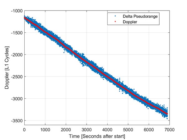
To derive an improved position from this class of device pseudorange and Doppler can be fed into a code-phase positioning engine. Fortunately, the Doppler provided by the device is of reasonable quality as can be seen from Figure 2.
Figure 2. Android GNSS observables: Doppler versus time-differenced pseudorange.
In this simple analysis measurements from a single high elevation satellite were analyzed. The Doppler is plotted along with the differenced pseudorange converted into L1 cycles. It can be seen that as expected the Doppler has much lower noise and so can be used in a pseudorange smoother.
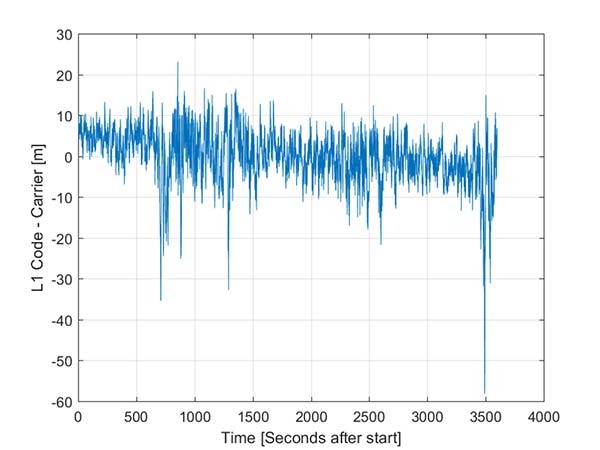
A simple way to view the pseudorange noise is to subtract the carrier phase from the pseudorange. If there are no cycle slips this should show ionospheric divergence with the noise dominated by the pseudorange noise. The absolute level is arbitrary as it includes integer carrier cycles. Figure 3 shows an example from an Android device.
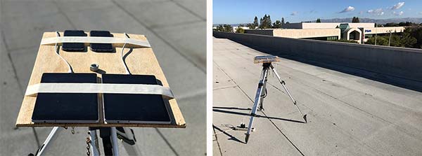
The data was captured on a building roof in an open environment. There’s a slight downward trend due to the ionospheric divergence between code and carrier, but the metric is dominated by the pseudorange noise. For this example from a high elevation GPS satellite the standard deviation is 6.5 meters. For comparison, a precision receiver connected to a precision GNSS antenna providing unsmoothed pseudorange in this environment would have a standard deviation of a few decimeters.
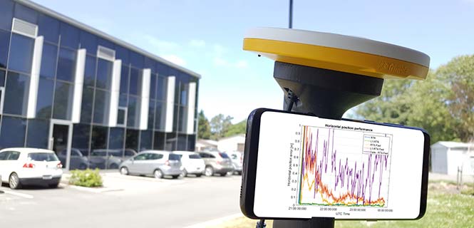
Another way to assess the measurement performance is to form double difference residuals. Data was logged from pairs of identical devices mounted with a common orientation. An RTK system was used to measure the same point on each device. The camera lens location above the screen was used as the reference point.
An accurate vector between the two references points was computed and used as truth in a double-difference residual analysis. Even though we do not know the precise location of the phase center of the antenna, because the difference was performed between two devices that are the same model and have the same orientation the error in the phase center location is common and will cancel. Various pairs of devices were tested by being mounted on a wooden board on a tripod at approximately waist height. The test configuration is shown in Figure 4.
Figure 4. Android device test configuration.
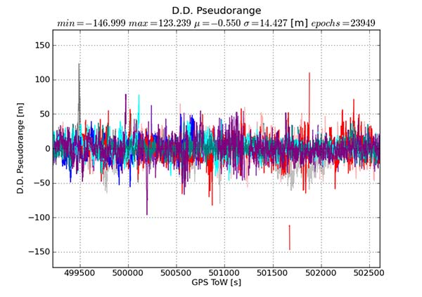
Figure 5 provides the double difference GPS L1 C/A pseudorange residuals between two Android devices. We see errors beyond 100 meters and a standard deviation across all data of 14.4 meters. A precision system (RTK or RTX/PPP) would use a standard survey quality base or network of bases and not an Android device for the correction data.
Figure 5. Short baseline double-difference pseudorange, Android devices.
Consequently in a typical operating mode where a precision data stream provides corrections, the contribution in a double difference from the pseudorange on the Android devices would be roughly half the Android-to-Android residual seen in this test or approximately 7.2 meters for this example.
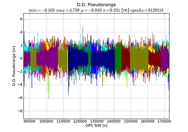
For comparison, the same metric was generated between two precision GNSS units connected to antennas on the same roof. While the data was not from the same time period, we observe very consistent performance over time.
Figure 6 shows the same pseudorange double difference across a short baseline over 24 hours. When comparing Figures 5 and 6, note the difference in the scale on the pseudorange residual axis. The standard deviation from a pair of precision devices is 53 centimeters (cm) or 27 times lower noise than an example pair of Android devices.
Figure 6. Short baseline double-difference pseudorange, precision devices.
All phones that provide GNSS measurements via the Android API publish the phase data in the accumulated delta range field. An accumulated delta range is not necessarily a full phase measurement; it can have an arbitrary starting phase.
For example, in a precision GNSS receiver, if the receiver locks to a satellite and some time later locks a second channel to the same satellite, the phase measurement from the two channels may have a different integer cycle component, but the subcycle component would be the same except for millimetric tracking noise.
If the two channels are providing accumulated delta range the initial phase offset may differ by up to one cycle. From the population of Android devices that publish phase that we have tested we have not observed any devices that deliver true full phase.
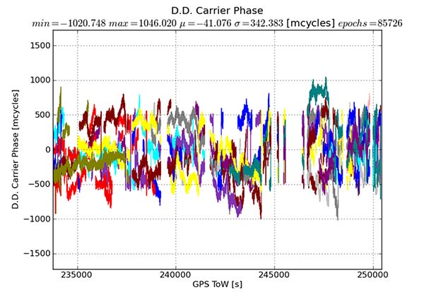
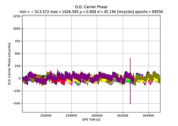
They all deliver an accumulated delta range with an arbitrary phase offset. This limits a phase engine to float processing and ambiguity fixing is not possible. The Android phase data collected from the previously described experiment was processed to provide the double difference carrier residuals. This is shown in Figure 7.
Figure 7. Short baseline double-difference phase residuals, Android devices.
The y-axis is in millicycles (1,000 millicycles = 1 cycle or approximately 19 cm for L1 GPS). Jumps are seen as the reference satellite changes or when the measurements have cycle slips. In this case the standard deviation is 342 millicycles. A double difference residual on a precision receiver in a similar environment with a high-quality antenna on a short baseline is an order of magnitude lower than this.
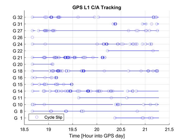
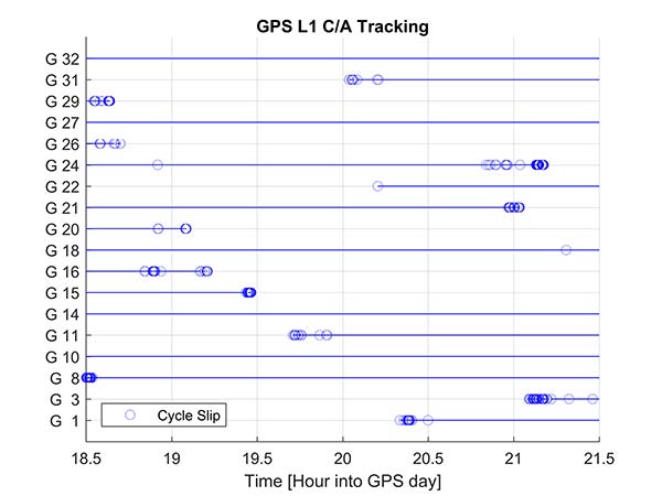
Another useful metric to review are the number of reported cycle slips. Figures 8 and 9 show a comparison of the cycle slips reported on GPS L1 C/A from an Android device compared to data logged on a precision receiver over the same time span. The receiver tends to only cycle slip at low elevation; the device had a zero-degree mask. The Android GNSS device cycle slips at higher elevations, probably a result of deep multipath fades due to the poorer antenna.
In an ION GNSS+ 2017 paper, we showed the achievable position performance using an RTK engine that had been previously customized to operate with measurements from consumer GNSS chipsets. It operated in a float mode due to the sub-cycle issue found in phase data from Android devices.
We also demonstrated the performance from a precision code-based PVT engine that had changes to the a priori measurement error estimate, a modified pseudorange/Doppler Hatch filter and used SBAS data to correct the position. As very few current Android devices deliver phase information the two engines were used to analyze what is possible today with the pseudorange and may be available in the future as phase is more universally available.
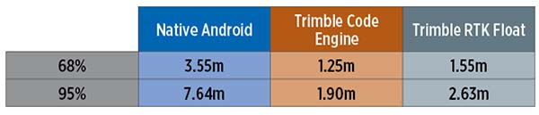
Data was processed from a Nexus 9 tablet, the only known Android device that has GNSS power duty cycling disabled. The unit was unmodified and so the Android tablet’s integrated GNSS antennas were used. The 2D performance is given in Table 1.
Table 1. 2D performance from Nexus 9 Android tablet.
Only GPS L1 and GLONASS L1 measurements were used and the RTK float solution delivered similar performance to the pseudorange solution. This is due to a combination of issues, very high pseudorange noise, and a significant number of cycle slips (see Figures 5 and 8). Only single frequency data was available, and while the engines used had been tuned for consumer data, they were not specifically designed for this class of data.
Next-Generation Phones
Within the next couple of years improved chipsets are expected to be available to consumers that will result in improvements in achievable positioning performance. In May 2017, Broadcom provided us with a development kit for its next generation L1/L5 multi-system BCM47755 GNSS chipset. This allowed us to assess what may be possible when improved GNSS chipsets are integrated in the next generation of cellular devices.
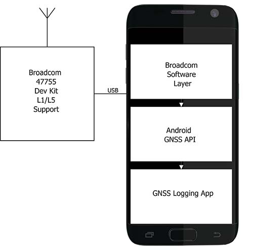
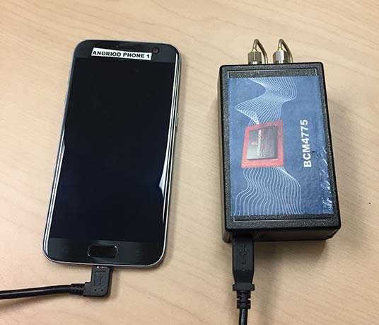
Figure 10. Broadcom BCM47755 development system.
The development environment included the GNSS chipset with an external antenna port so both a cell-phone equivalent antenna and a precision antenna could be compared. This allowed us to evaluate the impact of the antenna performance on the GNSS observables and positioning results. The Broadcom GNSS development system communicates via USB to a Samsung S7 phone and publishes data via the Android GNSS measurement API so the equivalent data flow of an integrated cellular device is maintained (see Figure 10).
In our ION paper, we showed the typical phase double-difference residuals observed from current Android devices. The Broadcom BCM47755 originally provided similar performance, although it also supports GPS L5 and Galileo E5A. In November 2017, Broadcom provided a firmware update that resolved the sub-cycle phase issues. With the updated Broadcom software, the double difference carrier residuals for GPS L1 on a zero baseline when differencing a precision receiver to a Broadcom BCM47755 are shown in Figure 11.
Figure 11. Precision GNSS to Broadcom BCM47755 zero baseline double difference carrier-phase residuals.
The standard deviation is 45 millicycles which is approximately 8.6 millimeters (mm). This is substantially better than earlier implementations of the Android GNSS interface (see Figure 7) and sufficient to perform RTK ambiguity resolution.
The rest of the results in this article were obtained with the improved firmware along with a new precision position engine. This engine was designed from inception to support GNSS measurements with differing quality and so can more optimally process the Android GNSS data. The effect of the improvements to the Broadcom firmware and the change in the processing engine can be seen if the results in our ION paper are compared to the data in this section.
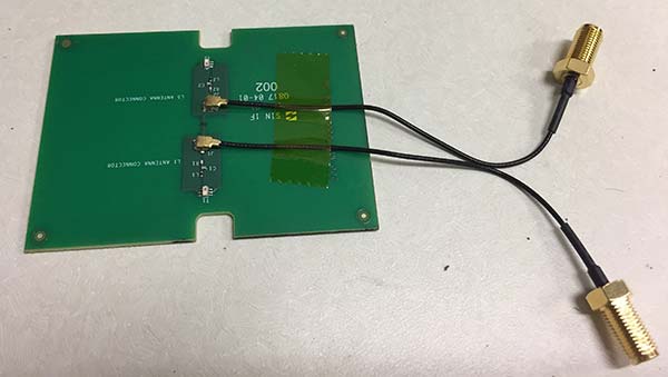
To attempt to model what may be possible with a phone based on a next-generation chipset, a cell-phone equivalent antenna provided by Broadcom was used in some of the tests with the development system, as shown in Figure 12. This device has separate feeds for L1 and L5.
Figure 12. Cellular equivalent antenna.
Datasets were collected with the multi-frequency GNSS BCM47755 device. The data was captured in the Android GNSS measurement API format and converted to proprietary format files for further processing. All data was collected in Sunnyvale, California.
Measurements from GPS L1/L5, Galileo L1/E5A, GLONASS L1 and BeiDou B1 were logged and analyzed. The Precise Positioning Engine (PPE) allows performing carrier-phase RTX and RTK and a pseudorange-based solution using the RTX corrections. Tests were performed by using a precision antenna and a cell-phone equivalent GNSS antenna.
With Precision GNSS Antenna
These datasets were collected on a zero baseline with a precision receiver to allow a direct comparison of results with a professional receiver. The first test was on Nov. 22, 2017, where the Broadcom GNSS chip and the receiver were connected to the same professional antenna.
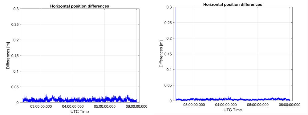
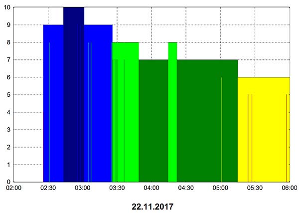
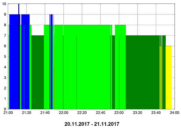
As seen in Figure 13, both GNSS receivers provide centimeter-level accuracies after some convergence time. With the current satellite constellations, only a third of the GPS satellites have L5 and only about half of the E5-capable Galileo constellation is in space. During this 3.5-hour test, the number of dual-frequency measurements processed by the engine that used the Broadcom chipset — data that does not support L2 — ranged between 6 and 10 satellites (Figure 14).
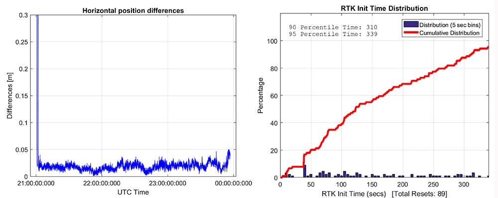
Figure 13. RTK performance for a 3.5-hour dataset sampled on Nov 22. Broadcom chip at left and precision chip at right. A short baseline was used — precision antenna.Figure 14. Number of GPS L1/L5 plus Galileo E1/E5A dual-frequency measurements used by the position solution based on the Broadcom chipset — precision antenna.
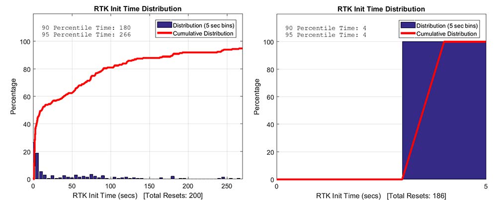
Convergence times were measured with post-processing tools by splitting the datasets into individual time spans. Figure 15 shows that the consumer GNSS chipset is able to get fixed ambiguity solutions but it takes considerably more time (266 seconds versus 4 seconds) for the 95% of initializations. However, the system is fixing ambiguities and provides centimeter level positioning.
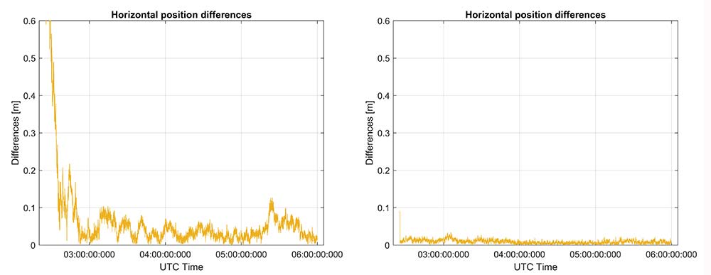
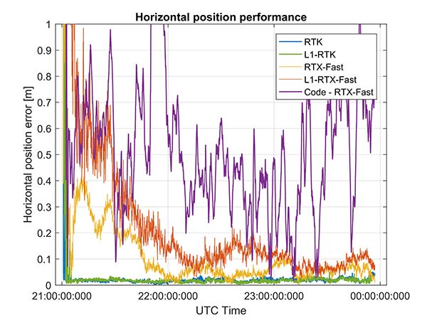
The same datasets were also processed with RTX-Fast in California. Thus the base station data was replaced by a global/regional correction stream received from an internet-based data source (Figure 16).
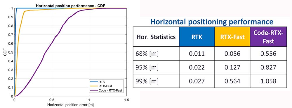
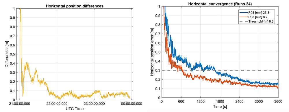
Figure 15. RTK initialization performance, dataset sampled on Nov 22. Broadcom chip at left and precision receiver at right — precision antenna.Figure 16. RTX performance for a 3.5 hour dataset sampled on Nov. 22 (Broadcom chip at left and Trimble chip at right) — precision antenna.
Horizontal accuracy for Broadcom reach 10 cm while the precision receiver reaches better than 3 cm. The degradation is in part due to the difference in quality of the carrier phase and the different number of dual frequency satellites processed. Precision devices provide measurements on E1/L1, L2 and L5/E5 providing at least dual frequency data from GPS, GLONASS, Galileo, BeiDou and QZSS.
The Broadcom chipset tested provided dual frequency GPS and Galileo along with single-frequency GLONASS and BeiDou; however, due to limited BeiDou constellation visible in California, data from this constellation was not used.
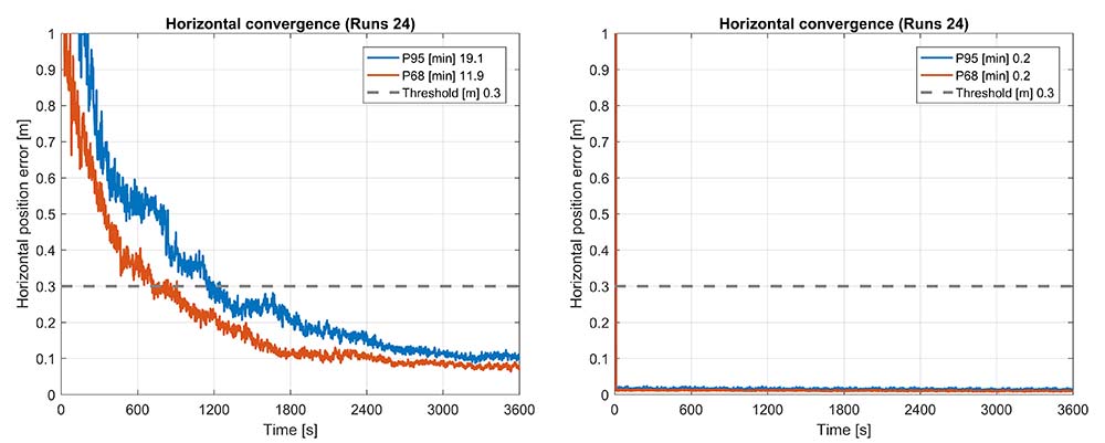
Convergence was also analyzed and is shown in Figure 17. From the data, we generated 24 convergence runs by taking one hour, progressively shifting the start time by 5 minutes and running the data with different start times through the PPE engine. This produced 24 runs, which were translated into 68% and 95% convergence statics shown.
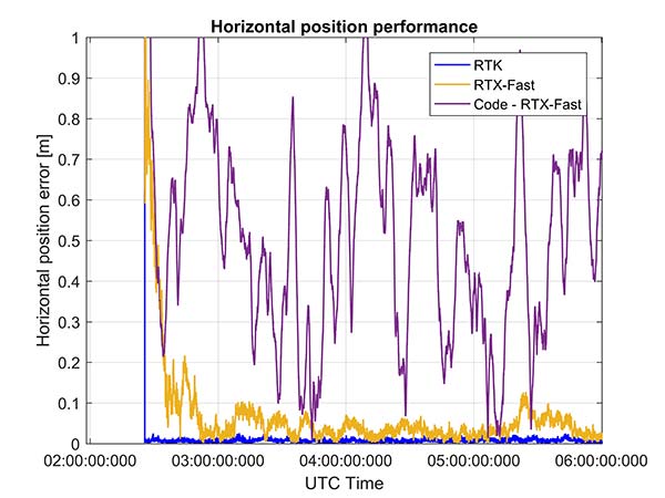
Figure 17. RTX convergence performance for a 3.5-hour dataset sampled on Nov. 22. Broadcom chip at left and precision chip at right — precision antenna.Figure 18. Code RTX performance for 3.5-hour dataset sampled Nov. 22 and corresponding RTK and RTX phase solutions — precision antenna.
The RTX-Fast solution for Broadcom reaches 30 cm horizontal error in 68% of the cases in approximately 12 minutes. The RTX-Fast convergence using precision GNSS data is near instantaneous as can be seen in the right of Figures 16 and 17, reaching centimeter accuracy.
The code position solution using the RTX correction stream provides sub-meter positioning (Figure 18).
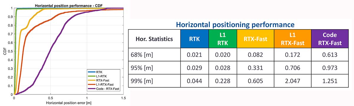
As a summary, the cumulative distribution function plots (Figure 19) show the performance differences for this static environment, on Nov. 22.
Figure 19. CDF plots for the different PPE position solutions — precision antenna.
Cell-Phone GNSS Antenna Results
Similar tests were performed using an external cell-phone GNSS antenna, which is close to the antenna used in a typical smartphone. RTK performance shows centimeter-level accuracies and reasonable convergence times, which are slightly worse than the results with the professional antenna (Figures 20–24).
Figure 20. RTK positioning and initialization performance for the Broadcom chip and the cell antenna sampled on Nov 20 — cell-phone GNSS antenna.Figure 21. RTX-Fast positioning and convergence performance for the Broadcom chip and the cell antenna sampled on Nov. 20 — cell-phone GNSS antenna.
In general as expected we achieve worse performance when connected to the GNSS cell-phone antenna for all the different positioning modes. For the cell antenna we also generated single-frequency RTK and single-frequency RTX-Fast position solutions and compare it with a code positioning solution.
Positioning Engine in Android
Figure 22. Number of GPS L1/L5 plus Galileo E1/E5A dual-frequency measurements used by the position solution based on the Broadcom chipset — cell-phone GNSS antenna.
The results presented in this article captured GNSS data using the Android API and then post-processed the data using PC versions of the position engines. A significant amount of data has been captured and analyzed using this method.
For the purpose of real-world demonstration the PPE has been implemented in an Android app to be used in cell phone devices. This PPE is able to provide RTK, RTX and code based positioning technology in one single PPE library.
The app has been tested running on a Samsung S7 connected to Broadcom’s new chipset development kit as well as a Nexus 9 tablet that uses an older generation GNSS chipset.
Figure 23. Code RTX performance, the dataset sampled Nov. 20 and corresponding RTK and RTX phase solutions — cell-phone GNSS antenna.
Future work will refine this solution as well as evaluate how well the system works when mobile. The data collected in this article operated in an environment with a clear view of the sky. We plan to characterize what happens when the platform moves with both pedestrian and automotive dynamics, as well as the effects of body masking and challenges with changes to the GNSS antenna reception pattern when the phone is held.
Summary
While this article has highlighted that sub-meter and centimeter accuracy have been achieved in a laboratory environment, there are many challenges to be addressed before centimeter accuracy in a phone can be achieved with performance suitable for users in real-world environments.
Figure 24. CDF plots for the different PPE position solutions for cell antenna dataset.
The challenges include very high multipath, significant differences in the tracking performance between different devices, and high rates of cycle slips. As very few Android-based devices provide continuous phase, a pseudorange/Doppler-based engine has been modified to accept Android data.
Based on the testing with existing devices it is possible to achieve position solutions of 1–2-meter accuracy in ideal static scenarios. This is a significant improvement in accuracy for Android based devices.
Figure 25. PPE engine on a Samsung S7 with a Broadcom BCM4775 evaluation kit.
However, as performance differences were observed between different mobile devices significantly more data needs to be collected over a larger set of devices to review the repeatability of these preliminary results from existing Android devices.
The Broadcom BCM47755 development kit for a dual-frequency GNSS chipset intended for future phones has allowed us to review the potential position performance that may be achievable in a handset in a few years.
By connecting this next-generation GNSS chipset to a GNSS antenna typical of a cellular device and comparing the performance from a precision GNSS antenna, we’ve shown for the first time that it is possible to produce precision positions from a static cellular class GNSS device in ideal conditions at the centimeter level with both an RTK solution and a PPP solution.
However, due to the significantly higher measurement noise and high multipath from the cellular device’s GNSS antenna, the convergence times to reach centimeter level remain a challenge; although using dual-frequency phase data from a cellular GNSS chipset with a PPE and RTX service, the position is very rapidly sub-meter.
Future work will focus on analyzing how the performance changes when operating in the normal user environment. The effects on the measurements of user motion, body masking and de-tuning of the antenna when the device is held need to be quantified. The Nexus 9 tablet used in this article does not have integrated cellular. The Broadcom development kit connects to the phone via a cable and is also not integrated into the handset.
We will be evaluating what may happen with a more integrated unit to make sure emissions from devices with integrated cellular very close to the GNSS antenna do not result in further degradation.
As the position performance is very sensitive to the quality of the antenna from both multipath and cycle slips due to low C/NO and deep fades, we’ll also evaluate how well the performance of the PCB-based GNSS antenna, which is part of the BCM47755 evaluation kit, matches current handsets.
Acknowledgment
This article further develops work first shown in an ION GNSS+ 2017 paper, “On the Path to Precision — Observations with Android GNSS Observables.”
Manufacturers
Trimble CenterPoint RTX is the satellite orbit and clock corrections service used here, enabling a PPP-like positioning with ambiguity fixing, providing better than 4 cm with typically less than 10 minutes’ convergence.
RTX-Fast functionality in Europe and parts of California uses regional atmospheric models to provide better than 4-cm horizontal in typically less than one minute. When precision and professional receivers and RTK engines are mentioned in this article, they are Trimble devices, the BD940 receiver in some cases.
A Trimble Zephyr 3 antenna was used in many tests shown here.
By Bradford Parkinson Vice-chair, U.S. PNT Advisory Board
In the coming months, the U.S. Federal Communications Commission (FCC) may allow high-powered, ground-based, communication transmitters to broadcast at a frequency near GPS L1. U.S. Department of Transportation (DOT) tests have shown that such transmitters effectively become jammers for many existing GPS receivers.
I believe that this possibility is the greatest current threat to the position, navigation and timing (PNT) community.
L1 is the primary band for GPS as well as for similar GNSS. For example, the international signal called L1C is to be centered at L1, albeit with wider spreading than the current L1 civil signal, C/A.
Why is this of critical importance? An economics study that only considered a small subset of benefits concluded that the U.S. alone realized $65 billion per year in direct economic value. A more complete recent study for the UK, extrapolated to the U.S., estimated the total impact of the loss of GPS to be over $3 billion per day for a five-day outage — a far greater rate. Virtually all GPS applications rely on the signals at L1. Thus, any threat to GPS is not simply an inconvenience, it would have great potential to do economic harm.
The PNT Advisory Board (PNTAB)has been trying to protect PNT, particularly GPS, and at the same time accommodate Ligado, a company that has requested repurposing of nearby spectrum. At our November meeting, we reviewed the Ligado proposal and framed a response that will be made public in due time. Meanwhile, these observations and conclusions are my own.
History
In 2011, LightSquared proposed that existing restrictions on its existing frequency authorization in the Mobile Satellite Service (MSS) band (a faint signal, satellite-to-ground) be waived so that the band is effectively repurposed to allow for high-power terrestrial transmissions.
The company has two space-to-ground authorizations in the 1525–1559 MHz band (1526–1536 MHz and 1545–1555 MHz) very close to the GPS primary frequency (L1 at 1575MHz). Initially it requested repurposing to ground transmission of 42 dBW (15.8 kW).
Faced with tests and analysis that showed this would be very destructive to GPS, it proposed to abandon the closer band and reduce power in the further band to 32 dBW, or 1580 Watts.
Ligado filings suggest a spacing of approximately ¼ mile between transmitters. A GPS receiver would find even these weaker signals 5 billion times the power of GPS at the maximum range of ¼ mile.
Most PNT users would be much closer.
International criterion
To ensure ranging accuracy, the international standard for interference to GPS is a 1-dB increase in noise levels. In conventional terms, this max allowable 1 dB is a 25.8% increase in background noise. The power of the weak GPS signal is only about 1% of the background radio noise. Sophisticated signal processing algorithms allow the signal to be reconstructed.
The result: the international 1-dB standard is equivalent to a 25% reduction in GPS radiated power.
Two additional points
The 1 dB is not simply to protect signal lock, it is to protect ranging accuracy. Most GPS receivers will stay locked for higher levels of interference but lose high precision. This is particularly a problem for high-precision receivers, which need relative timing to sub-nanosecond accuracies.
These measurements are equivalent to the time it takes light to travel ¼ inch. Protecting such accuracies is of paramount importance to PNT users and applications.
Allowing such maximum degradation from a single source is not the whole picture. There are many other potential sources of interference and attenuations of the GPS signal. For example, foliage may reduce the GPS signal.
A receiver must cope with all of these difficulties. Allowing a single cause, such as the Ligado repurposing, the 25.8% equivalent reduction might be considered quite generous, but it is the accepted International Standard.
Ligado has specifically rejected this criterion, largely because testing has shown that the Ligado repurposing would then be unacceptable for many PNT user classes.
To support its rejection of the International Standard, Ligado has repeatedly alleged that five of the major manufacturers are in complete agreement regarding its repurposing. This is a substantial distortion. The record was set straight by Brian Ramsay of MITRE at the November PNTAB meeting: “Four of the five parties that reached agreements with Ligado (except for Topcon Positioning) support the 1-dB Interference Protection Criterion (IPC) in comments filed in response to this Public Notice.”
Further support was highlighted by Captain Robyn Anderson: “In June 2017, the Air Force produced a white paper on the 1-dB IPC that explained the relationship between harmful interference (levels that affect GPS receiver performance) and the 1-dB IPC (keeps interference below a level that would cause harmful interference).”
Lightsquared’s motivation in 2011 was clear: a $10 billion windfall profit (estimated increased value of the spectrum on open-market auction). The FCC did not confirm Lightsquared’s modified request, and in 2012 the company went into bankruptcy.
Reorganizing as Ligado and emerging in December 2015, it continued to pursue repurposing of its spectrum, sponsoring tests by Roberson and Associates, and tests at National Institute of Standards and Technology (NIST)/National Advanced Spectrum and Communications Test Network (NASCTN) to establish test procedures.
Both groups of tests were carefully reviewed by our PNTAB who found serious flaws. In general, Ligado rejected the 1-dB criterion and did not accept the need to protect all classes of users, particularly high-precision receivers. In addition, it did not consider the new GPS L1 signals (L1C and L1M), nor did it check the impacts on the international GNSS. The PNTAB assembled a 14-point summary of deficiencies and requested updates and corrections for the flaws.
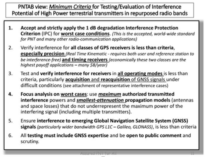
NASCTN’S response did not really address the points, or claimed that there were no funds to correct the problems. The PNTAB then developed a Six-Point Criteria for acceptable interference testing,summarized as:
Accept and strictly apply the 1-dB criterion.
Verify interference for all classes of receivers.
Test and verify for all operating modes.
Focus analysis on worst cases.
Include the new GNSS signals.
Include GNSS expertise and openly publish results.
Image: PNTAB
We believe it is a very reasonable set that aims to protect PNT users and our economic benefits. In its sponsored tests, and in representations to the FCC, Ligado has consistently overlooked a basic facet of radio ranging: it is ranging accuracy, not simply locking onto a signal, that is the fundamental objective for PNT.
Both Ligado test sets clearly failed on all six points.
DOT ABC tests
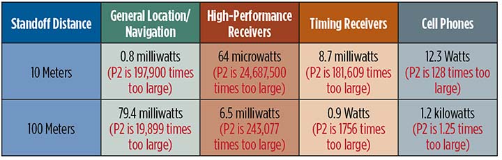
While the Ligado-sponsored tests were neither independent nor adequate, the Department of Transportation, led by Karen VanDyke, sponsored a very complete set of independent tests; these are the most credible estimates of harmful interference. The ABC results have been made public. The PNTAB’s six points were published after DOT testing had begun, but DOT expanded and modified their effort to satisfy the criteria. The DOT conclusions, based on modeling real-world antennas and propagation patterns, are shown in Table 1.
TABLE 1. DOT ABC test results. Maximum tolerable effective radiated power (EIRP) for classes of the most susceptible GPS receivers for modified Ligado proposal (P2) of 1.58 kilowatts. In red are the factors that Ligado P2 exceeds the maximum tolerable radiated power. (Chart: GPS World)
At 100 meters, all classes of receivers tested had results that would exceed the 1-dB threshold, even for the reduced power level (P2, 1580 Watts) that has been the most recent filing. The shaded square is particularly troublesome. It shows that, for the most susceptible high-precision receivers, the Ligado proposed power exceeds the 1-dB threshold by over 200,000. This result is particularly damning for the proposed repurposing, because it is this class that produced the highest payoff in the recent Department of Commerce Study — over $30 billion per year.
PNT operations at risk
These are examples of unintended and potentially hazardous consequences of repurposing.
UAVs. Unmanned aerial vehicles (drones) will fly very close to the dense array of transmitters that Ligado would deploy. They usually require GPS for flight control. Even more important, if we are to monitor them and keep them from collisions, GPS offers the only viable techniques with 3D accuracy and almost 100% availability.
Precision survey. This is routinely used in urban areas for building construction and is a major source of productivity gains. These survey receivers are all high precision and routinely make measurements to better than ¼ inch.
Helicopters. These are found in urban area at all altitudes. They are used for law enforcement, rescue and passenger transportation. GPS is mainly used for general navigation.
Public safety vehicles. Fire, police and ambulances use GPS for both navigation and dispatch tracking. In a city, they would drive in and out of susceptible high-interference zones.
The PNTAB believes the DOT results are representative, accurate and credible. The National Coordinating Office for PNT also sponsored an evaluation of all testing to date. A summary report is now in coordination, as a combined Department of Defense (DOD) and DOT effort.
The DoD, which uses GPS in the national airspace for routine flight, testing, training, guiding rocket launches, and for humanitarian rescue missions, has opposed repurposing. The Air Force reported, “Results from the DOD ABC Assessment support the conclusions drawn from Department of Transportation’s ABC Assessment.”
November PNTAB meeting
At our November meeting, the board invited Ligado to make a presentation on its repurposing proposal. The invitation said: “Specifically describe your implementation plan, with a corresponding test plan addressing the issues we have openly raised. We request you specifically focus on those regarding the potential for interfering with any GPS/GNSS services that operate in the protected space-to-Earth L-band (1559–1610 MHz). Included should be all modes of operation and the use of all current and future GNSS signals.”
Valerie Green, executive vice president and chief legal officer of Ligado Networks, represented Ligado. In the run-up to the meeting, the Six-Point Criteria had been sent to Ligado. Green did not address the six points at all.
She did offer to reduce initial power to “the safe power level in the 1526–1536 MHz channel ranges from 9 to 13 dBW EIRP nationwide,not just near airports.”
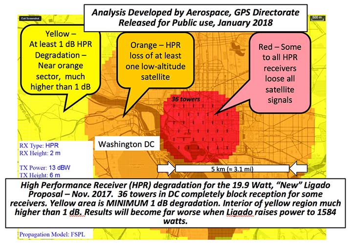
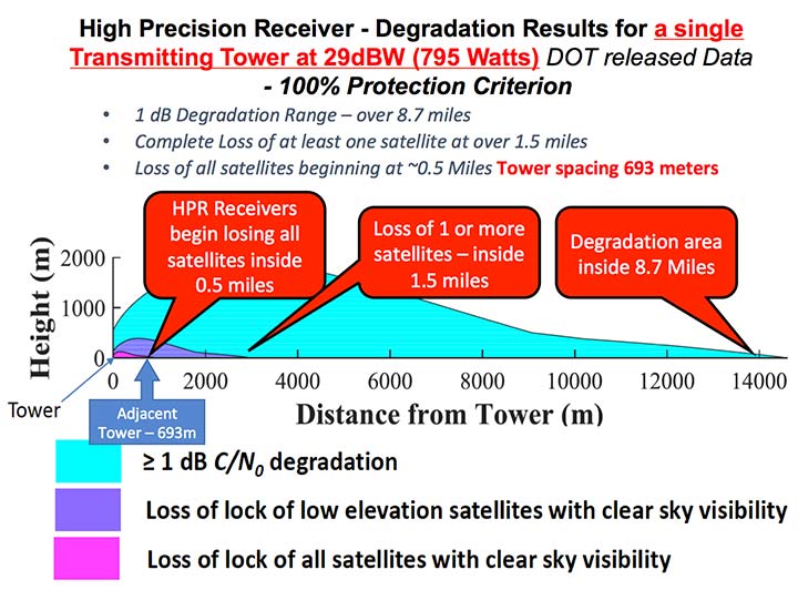
FIGURE 1. Potential impacts on high-performance receivers. Red: loss of lock of all satellites. Yellow: loss of lock of low-elevation satellites. Green: 1-dB degradation. (Chart: PNTAB)
The 13 dBW corresponds to initial power levels of 19.95 W. However, Ligado has made clear in its FCC filings that it ultimately still wants a full 32 dBW base-station transmit power level, consistent with typical 4G/LTE networks.
The initial reduced power sounds like a major move in the right direction, but further questioning revealed two major issues:
Tower Spacing. Green was very evasive on the spacing of transmitter towers. Clearly, at the reduced power level, greater density would be needed to carry the original data bandwidth. At about 1/100th the power, density would have to increase by a factor of 100, and the spacing would have to decrease to 1/10th for the same data output rate.
Green referred us to an earlier filing which specified 0.25 mile, but did not clearly state that this was the plan; she claimed the details were proprietary. If this fundamental parameter, spacing, is not specified, it is hard to see the basis for the FCC evaluation of any new proposal. If the transmitter spacing is reduced to less than 1/10th of a mile, the sources of potential harm would be multiplied in a very worrisome way.
Future power constraint.A public presentation does not ensure that Ligado will actually file and agree to abide by those power constraints indefinitely. Board members pressed Green on the permanence of the power constraint.
She suggested it would be tied to the RTCA Minimum Operational Performance Standard. Revising the MOPS takes many years, if not decades, both to formulate and to implement. Retrofitting the commercial aircraft fleet is very expensive and time-consuming.
Further, her statement focuses only on commercial aircraft, ignoring the high-precision classes as well as future signals.
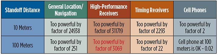
A modified summary chart (Table 2) for the lower power, based on the DOT ABC test results, shows that even at the lower power, the threshold for high-precision receivers is exceeded by a factor of over 3,000 at 100 meters. In fact, only cell phones, which are relatively inaccurate, could operate at 100 meters without exceeding the threshold.
TABLE 2. Results of DOT ABC test with Ligado transmitters constrained to 19.95 Watts (13 dBW). This illustrates that the International Interference Limit is exceeded many times over at 100 meters for certain high-precision receivers, highlighted in red. (Table: GPS World)
With these expectations and uncertainties, the PNTAB did not find the new revision acceptable to the PNT community.
Three fundamental issues
Ligado has steadfastly not accepted the realities of non-interference.
1 dB. Acceptance of the 1-dB (25.8% noise increase) International Interference standard is fundamental to protecting GPS applications throughout the country.
All current and future uses. Users of great concern are emergency services, helicopter and general aviation, UAVs, and precision survey and machine control. For example, many of the underground utilities in the U.S. have been mapped with precision, GPS-based, geographic information receivers. This application requires sub-meter accuracy and operates in both rural and urban environments.
Ligado has tended to simply focus on certified aviation, claiming that protecting that class of user is enough. The PNT community rejects that view. All current and future PNT users must be protected.
Worst–case interference. The recent round of testing was largely in a laboratory. Extrapolating to the real world must examine the situations with greatest interference. For example:
Number of simultaneous interfering transmitters. A single transmitter situation is not typical; three or more are apt to be in range. The additive power must be considered.
Propagation models. Propagation models for communications differ from those for evaluating potential interference to a navigation signal. For assured communication, a typical model assumes transmitted signal fall-off a little faster than 1/(distance squared). Ligado would naturally prefer to use this model, which is far from worst-case for interference. The early round of tests in Las Vegas verified the communications model would vastly underestimate interference levels, by factors of 10 or more. A more realistic model must be used.
Degradation Radius. This is the size of the circle within which the International Standard is violated for receivers in a specified class. If the spacing of transmitters is 400 meters, and the degradation radius is 200 meters, virtually all receivers are in the degradation zone. Ligado suggested an appropriate degradation radius is 250 feet for aviation (approximately 100 meters). Thus, they claim the PNT community should tolerate violation of the standard when closer than 100 meters to their transmitters. At 400 meters spacing, 25% of the area would be in violation.
But the ABC test results reveal a much graver situation. They show that, for the current Ligado proposal (1580 watts), the degradation radius is over 14 kilometers for high-precision receivers. See Figure 2.
The 1-dB criterion is the correct, accepted and somewhat generous allocation of interference that can be accepted by the PNT community. We would hope that the FCC would continue to insist on this standard.
PNT users must, yet again, defend the spectrum vigorously. Most of us are scientific and technical people. We are not used to discussions that deliberately avoid the technical issue or deny scientific evidence. We reject arguments that violate the fundamental laws of physics.
The currently filed proposal, 1580 Watts at spacing of ¼ mile, is unacceptable. It will do grave harm to many important PNT applications
We must be very leery of the new proposal by Ligado of 9–13 dBW. It still would violate the 1-dB criterion at 100 meters for many PNT users.
Moreover, the company history has been to bait and switch; it has an authorization for MSS Ancillary Terrestrial Component (MSS ATC) stations to fill the gaps in satellite coverage with ground transmitters. These must operate in conjunction with the space-to-ground link that made them effectively self-limiting. However, in 2011, it almost succeeded in switching this to a ground-only system, which would have achieved a huge financial windfall.
Open-air verification
If the FCC continues to consider this proposal, there is one step that it should take before granting it. It should require Ligado to deploy an array of transmitters in its advocated configuration, and run real-world, open-sky testing to assess the harm that may result, particularly to high-precision accuracy.
Such testing was done when the issue was first raised in 2011 and conclusively demonstrated unacceptable interference. Nothing has really changed from the baseline that was tested and found unacceptable then.
The company should carry the full financial burden of such a verification, under PNT supervision. The government, having already spent millions of dollars to defend the spectrum, should not bear the cost of such retesting.
Without this confirmation, it is hard to conceive of putting GPS and PNT at significant risk to satisfy investors who want to flip a company, after gaining “rezoning” permission for their spectrum.
From 20,000 feet altitude
If we examine the situation without the technical details, we have this: Fundamentally Ligado wants to provide service using its allocated frequency band for an unlimited number of Internet-of-Things installations.
It is not proposing a small, fixed number of transmitting towers located in isolated regions, but rather an accelerating deployment of private networks, many of which will be close to commercial and essential infrastructure where GPS use is critical.
It seems unrealistic that Ligado can or will reliably guarantee that these widespread installations will be continually adjusted and monitored to avoid GPS interference.
I believe the concept of allowing the installation of transmitting towers that, by design, will interfere with normal GPS use at some distance away opens the door to tacit approval of short-range (or not-so-short-range) GPS jammers.
While I can commend the entrepreneurial spirit, the Ligado proposal seems very reckless indeed. The incremental value of an additional broadband transmitting system when there are at least five already in existence seems trivial compared to the potential damage done to the modern utility named GPS.
I sincerely hope the FCC can find a spectrum swap or deny outright the current Ligado application.
Hemisphere GNSS (hall 2.1 / stand C2.008) has released the Crescent Vector H220, the next offering in a line of new and refreshed, low-power, high-precision, positioning and heading OEM boards.
The announcement was made at the Intergeo trade show, being held this week in Berlin, Germany. Hemisphere is showcasing the board at its booth in Hall 2.1, Stand C2.008.
The Multi-GNSS H220 by Hemisphere GNSS.
The single-frequency, multi-GNSS H220 provides added benefits over the prior generation H200 with a more robust positioning and heading solution and integrates Atlas GNSS Global Correction Service.
Designed with a new hardware platform, it offers true scalability with centimeter-level accuracy in either single-frequency mode or Atlas-capable mode that supports fast RTK initialization times over long distances, the company said.
The H220 offers fast accuracy heading of better than 0.30 degrees at 0.5-meter antenna separation in ideal conditions and aiding gyroscope and tilt sensors for temporary GNSS outages. The 109 x 71 millimeter module with 34-pin header is a drop-in upgrade for existing designs using the H200.
The latest technology platform enables simultaneous tracking of all L1 constellations including GPS, GLONASS, BeiDou, Galileo and QZSS, making it robust and reliable. The updated power management system efficiently governs the processor, memory and ASIC, making it ideal for multiple integration applications.
The H220 offers flexible and reliable connectivity by supporting Serial, USB and CAN for ease-of-use and integration. Optional output rates of up to 50 Hz are also supported.
Advanced Features. The H220 offers integrated L-band support for Atlas corrections providing global sub-meter position accuracy while Hemisphere’s Tracer technology helps maintain position during correction signal outages.
Integrators, developers and OEMs can maximize their performance by including the H220 in their systems for antenna pointing, marine survey, machine control, and any application where high-accuracy positioning and heading is required.
Unicore has launched its next-generation quad-system GNSS module, the UM482.
The UM482 is a multi-frequency high-precision heading module with a small footprint, supporting the satellite signals BDS B1/B2, GPS L1/L2, GLONASS L1/L2, Galileo E1/ E5b and SBAS.
The module is designed for applications such as robotics, drones, intelligent drives and mechanical control.
1-cm RTK positioning accuracy and 0.2-degree heading accuracy with 1-m baseline
Dual antenna input with support of antenna signal detection
Supporting simultaneous output of heading and positioning, 20-Hz data output rate
Adaptive recognition of RTCM input data format
On-board micro-electro-mechanical system (MEMS) integrated navigation
The UM482 GNSS RTK module adopts Unicore’s new-generation Nebulas II chip and UGypsophila real-time kinematic (RTK) algorithm.
Based on high performance data-sharing technology and the simplified operation system of the Nebulas II chip, the UGypsophila RTK algorithm dramatically optimizes matrix processing, the company said. It can involve all satellites from GPS, BDS, GLONASS and Galileo in RTK and heading processing, shorten RTK and heading initialization time to 5 seconds and significantly improve the reliability and accuracy of RTK and heading.
Furthermore, the UM482 integrates the onboard MEMS chip and U-Fusion integrated navigation algorithm, resulting in optimized continuity and reliability of accurate heading and positioning output in tough environments such as city canyons, tunnels and overpasses. Inputs of odometer and external higher performance inertial components are supported.
The UM482, along with all the UM and UB family of receivers, will be on display at booth B4018 for the duration of the Intergeo 2017 trade show, which takes place Sept. 26-28 at Berlin Exhibition Center, Berlin, Germany.
u-blox, Bosch, Geo++ and Mitsubishi Electric are establishing the joint venture Sapcorda Services to bring high-precision GNSS positioning services to mass markets, including autonomous driving.
Bosch, Geo++, Mitsubishi Electric and u-blox have created Sapcorda Services GmbH, a joint venture that will bring high-precision GNSS positioning services to mass-market applications.
The four companies recognized that existing solutions for GNSS positioning services do not meet the needs of emerging high-precision GNSS mass markets.
As a result, they decided to join forces to facilitate the establishment of a worldwide available and affordable solution for system integrators, OEMs and receiver manufacturers. Each partner brings its unique expertise to the joint venture Sapcorda Services.
Sapcorda will offer globally available GNSS positioning services via internet and satellite broadcast and will enable accurate GNSS positioning at centimeter level. The services are designed to serve high-volume automotive, industrial and consumer markets.
The real-time correction data service will be delivered in a public, open format and is not bound to receiver hardware or systems. More information will be made available later this year.
“We believe this initiative with Bosch, Geo++ and Mitsubishi Electric to create Sapcorda Services will bring a truly disruptive GNSS service offering to the market,” said Daniel Ammann, executive VP and co-founder at u-blox. “Key characteristics such as security, safety and mass-scalability, coupled with an attractive business model and an open approach — serving all interested GNSS receiver manufacturers alike — will be a game-changer across a large number of established and emerging applications.”
“We are looking forward to collaborating with our partners in this joint venture,” said Jumana Al-Sibai, member of the executive management of the Chassis Systems Control division of Robert Bosch GmbH. “Together, we want to create a GNSS positioning service that fully supports the requirements for positioning sensors in the automotive sector. Only with built-in safety and the highest levels of precision will we be able to make automated driving reality.”
“Geo++ anticipates defining the future of high precision positioning services with our partners at Bosch, Mitsubishi Electric and u-blox. The combination of the partners’ longstanding leadership in automotive and mass market solutions with Sapcorda’s commitment to push open formats will pave the way for a raft of next generation GNSS applications,” said Gerhard Wübbena founder & president of Geo++.
“Mitsubishi Electric aims to create a border-less global market for high-precision positioning systems where receivers will be able to enjoy real-time correction data services potentially interoperable with the Japanese government’s Centimeter Level Augmentation Service (CLAS) via the Quasi-Zenith Satellite System,” said Masamitsu Okamura, executive officer in charge of Electronic Systems at Mitsubishi Electric Corporation. “We believe that this venture will accelerate adoption of automated driving and safe driving support.”
Figure 1. Galileo constellation and occupation status of orbital slots (RAAN: right ascension of the ascending node, May 9, 2017). (Source: ESA)
What to Expect with the Current Constellation
This article demonstrates the benefits of Galileo integration for high-precision real-time kinematic (RTK) through representative case studies, considering baseline length, multipath impact and tree canopy.
The results confirm usability of the current Galileo constellation in high-precision RTK applications and show improved availability, accuracy, reliability and time-to-fix in difficult measuring environments.
Plus, Galileo-only RTK positions are compared with GPS-only and GLONASS-only solutions.
By Xiaoguang Luo, Jun Chen and Bernhard Richter, Leica Geosystems AG
Until now, based on simulated and observed data, the benefits of Galileo (FIGURE 1) for high-precision RTK have been investigated in single-base RTK and network RTK solutions. Building on the results of previous studies that frequently employed theoretic analysis and simulation, we present the benefits of Galileo for high-precision RTK based on real observations from the current Initial Operational Capability (IOC) satellite constellation. Using up-to-date real-time corrections including Galileo, we analyze the performance of network RTK under different measuring conditions with respect to availability, accuracy, reliability and time-to-fix.
To achieve the maximum inter-operability with other GNSS con-stellations, all the Galileo signals in the E1 and E5 band, i.e. E1, E5a, E5b and AltBOC (alternative binary offset carrier), are used for positioning in the latest proprietary firmware and receivers (see “Manufacturers” section for details).
The Galileo E1 signal is overlapped with the GPS L1 signal at a center frequency of 1575.420 MHz, whereas the Galileo E5a and GPS L5 signals are overlapped at 1176.450 MHz. As far as BeiDou is concerned, the E5b frequency of Galileo corresponds to the B2 frequency of BeiDou-2 at 1207.140 MHz.
The AltBOC signal is also supported in order to benefit from its superior performance in multipath suppression. The availability of more than two frequencies is beneficial for ionospheric modeling, which plays an important role in ambiguity resolution on the fly.
In addition, multi-frequency RTK provides more immunity to temporary interruption of GNSS signals caused by interference or by site-specific effects like multipath. When forming linear combinations, the incorporation of multi-frequency signals enhances flexibility and robustness, where the mathematical correlations introduced by including the same signal in different linear combinations of the same type need to be handled properly in RTK algorithms.
By enabling the tracking of Galileo satellites in the aforementioned firmware, the Galileo signals will be used in different RTK position types by default, including navigation position, phase-aided differential code position, extended RTK (xRTK) position and RTK fixed position. When compared to a standard RTK fix, an xRTK fix is provided at a slightly lower accuracy level, but with higher availability in difficult environments such as urban canyons and dense canopy.
In terms of RTK correction data formats, Galileo is included in the standardized RTCM v3 MSM format and in the proprietary 4G format. To use Galileo in network RTK, the real-time products provided by network correction services need to include Galileo as well. In the latest version of a proprietary GNSS network software, Galileo is used in network processing to provide RTK corrections via the individualized master-auxiliary (iMAX) method and the virtual reference station (VRS) method in the RTCM 3.2 MSM formats.
RTK PERFORMANCE CHARACTERISTICS
Multi-constellation and multi-frequency GNSS RTK is a complex real-time process, aiming to provide cm-level positioning accuracy with as few as possible data epochs for variable user kinematics and even in difficult measuring environments. Therefore, RTK performance characteristics need to be carefully selected to be able to evaluate the system as a whole and to address users’ concerns in their applications.
The following parameters are used in this article to assess the benefits of Galileo for high-precision RTK:
Satellite usage. Number of satellites used in RTK fixed solutions with an elevation cut-off angle of 10°;
Availability. Percentage of RTK fixed positions relative to all positions obtained during a time period;
Accuracy. Deviation of RTK fixed positions from ground truth with a higher degree of accuracy, where the ground truth can be determined by means of a total station or by post-processing long-term GNSS data;
Reliability. Percentage that the position error (with respect to ground truth) is less than 3 x coordinate quality (CQ) indicator;
Time to Fix. Time needed to regain an RTK fixed solution after losing ambiguity fix provided that GNSS signal tracking is not interrupted.
OPEN-SKY CASE STUDY
The open-sky case study was performed in the Heerbrugg testbed. Two receivers were connected to a single antenna via a four-way antenna splitter. One receiver received four-system iMAX corrections in the RTCM v3 MSM format over a short baseline of 2 km, whereas the other received RTK data of the same type over a long baseline of 116 km. By considering different baseline lengths, the open-sky experiment focused on the usability of the current Galileo constellation in GNSS RTK under normal conditions. Two days of 1-Hz GNSS data were investigated with respect to satellite usage and positioning accuracy.
Using different combinations of GNSS to analyze the short baseline data — GPS+GLO (GG), GPS+GLO+BDS (GGB) and GPS+GLO+GAL+BDS (GGGB) — the mean numbers of used satellites are 15, 17 and 20, respectively, where the elevation cut-off angle was set to 10°. On average, three Galileo satellites contribute to RTK fixed solutions.
For the four-system combination GGGB, Figure 2 shows the satellite usage for each individual system over the two-day period. It can be seen that for a short baseline of 2 km, a maximum number of four Galileo satellites can be used for positioning. In fact, during 80.3% of the whole test period, the number of Galileo satellites used in RTK fixed solutions is equal to or greater than the number of BeiDou satellites used.
Figure 2. Number of satellites used in RTK fixed positions with GGGB under open sky (iMAX, RTCM v3 MSM, baseline length: 2 km, GGGB: GPS+GLO+GAL+BDS, DOY: day of year).
Table 1 provides statistics on Galileo satellite usage in case of GGGB for different baseline lengths. As would be expected, the number of Galileo satellites used decreases with an increasing baseline length. In approximately 41% of the cases, three Galileo satellites are used in the short baseline test, whereas two Galileo satellites are used in the long baseline test.
Moreover, the probability that no Galileo satellites are involved in a four-system combined solution grows significantly from 1.9% to 15.0% as the baseline length increases from 2 km to 116 km. The probability that only one Galileo satellite is used under open sky is relatively small, amounting to around 0.5%. This is reasonable since no benefits for high-precision RTK are expected in this particular situation. Regarding the short baseline case, there is a 97.7% probability that at least two Galileo satellites are used for positioning, whereas this probability decreases to 84.4% in the long baseline case.
Table 1. Probability [%] that n Galileo satellites are used in RTK fixed positions with GGGB during the two-day period of the open-sky experiment (iMAX, RTCM v3 MSM, GGGB: GPS+GLO+GAL+BDS).In terms of positioning accuracy, Figure 3 compares the 3D errors from analyzing the long baseline data with different GNSS constellations. Regarding the entire two-day period illustrated in Figure 3a, the integration of BeiDou (GG vs. GGB) and Galileo (GGB vs. GGGB) results in higher position repeatability with more consistent errors. For a selected period of 12 hours, Figure 3b highlights the advantages of Galileo in reducing large 3D errors from 6–8 cm to 3–4 cm, where two or three Galileo satellites are used in case of GGGB.
Figure 3. 3D errors of RTK fixed positions under open sky (iMAX, RTCM v3 MSM, baseline length: 116 km, GG: GPS+GLO in green, GGB: GPS+GLO+BDS in blue, GGGB: GPS+GLO+GAL+BDS in red, DOY: day of year) (a) Entire two-day period, (b) Selected 12-hour period (28–40 h).
MULTIPATH CASE STUDY
In this case study, a GNSS smart antenna was set up in a location with strong multipath effects, where GNSS signals were obstructed and reflected by the surrounding buildings (Figure 4). This test setup simulates the use case that a user measures a point near a building with degraded GNSS signal reception, even at high elevation angels.
Figure 4. Test setup in a strong multipath environment in Heerbrugg (rover: GS16, antenna height: 1.8 m) (a) View from the south, (b) View from the north.
The default elevation cut-off angle of 10° was applied. The receiver received four-system VRS corrections in the RTCM v3 MSM format, where the distance to the physical reference station was approximately 200 m. Three hours of 1-Hz GNSS data were analyzed with respect to accuracy, reliability and time to fix.
Figure 5 illustrates the 3D errors from multi-GNSS RTK with and without Galileo (GGGB vs. GGB), along with the number of used satellites. Regarding the periods marked with dashed rectangles, the inclusion of two or three Galileo satellites (Figure 5b) leads to significant improvements in positioning accuracy at the few cm to dm level (Figure 5a). By comparing the empirical cumulative distribution function (CDF) of the 3D errors, the probability that 3D error is within 5 cm increases from 70% to 85% if Galileo is used, even with a maximum number of three satellites.
Figure 5. Impact of Galileo integration on RTK positioning accuracy under strong multipath (VRS, RTCM v3 MSM, GGB: GPS+GLO+BDS in blue, GGGB: GPS+GLO+GAL+BDS in red, DOY: day of year) (a) 3D errors of RTK fixed positions, (b) Number of used satellites (Galileo in green).
Tables 2 and 3 provide the root mean square (RMS) errors and reliability of RTK fixed positions from the multipath experiment, respectively. By using Galileo in high-precision RTK, the 3D RMS error is significantly reduced by 56.3% in this case study, from 0.080 m (GGB) to 0.035 m (GGGB). When compared to the horizontal components, the height RMS error shows a larger relative improvement of 58.7% due to Galileo integration. The reliability reflects the consistency between the actual position error with respect to ground truth and the CQ indicator estimated based on mathematical models in RTK algorithms. As shown in Table 3, the 3D reliability improves by 7.3%, from 88.2% (GGB) to 95.5% (GGGB), where the increases for the horizontal components and height are comparable.
Table 2. Root mean square errors [m] of RTK fixed positions under strong multipath (VRS, RTCM v3 MSM, GGB: GPS+GLO+BDS, GGGB: GPS+GLO+GAL+BDS).Table 3. Reliability [%] of RTK fixed positions under strong multipath (VRS, RTCM v3 MSM, GGB: GPS+GLO+BDS, GGGB: GPS+GLO+GAL+BDS).The time to fix (TTF) was determined by constantly re-initializing RTK once an ambiguity fix was gained. During the whole period of repeatedly resetting the RTK filter, the GNSS signals were tracked continuously without interruption. A total of 765 TTF values were obtained with GGB, whereas 1,128 TTF estimates were available with GGGB. The significantly larger number of the TTF samples from GGGB indicates higher availability of RTK fix if Galileo is used.
Figure 6 shows the statistical distribution of TTF with respect to Galileo integration. As can be seen in the empirical CDF in Figure 6a, it takes shorter time for GGGB to regain an ambiguity fix. As an example, GGGB allows ambiguity resolution within 5 s (10 s) with 46% (87%) probability, which is 29% (16%) higher than GGB. Regarding the boxplots of TTF in Figure 6b, GGGB shows a smaller median (by 25% from 8 s to 6 s) and a smaller interquartile range (IQR; by 50% from 4 s to 2 s) than GGB, where the IQR is the length of the box. This indicates that the integration of Galileo enables a faster ambiguity resolution with more consistent fixing performance.
Figure 6. Impact of Galileo integration on time to fix (TTF) statistics under strong multipath (VRS, RTCM v3 MSM) (a) Empirical cumulative distribution function (CDF) of TTF, (b) Boxplot of TTF with median and interquartile range (IQR).
CANOPY CASE STUDY
In this case study, a receiver was connected to an antenna under tree canopy (Figure 7), where GNSS signals are blocked, attenuated and reflected, leading to decreased number of observations, low data quality and degraded RTK performance.
Under these circumstances, the inclusion of Galileo satellites transmitting multi-frequency signals could be particularly beneficial for high-precision RTK. Using an elevation cut-off angle of 10°, the receiver received four-system iMAX corrections in the RTCM v3 MSM format, where the baseline length was 116 km. A long baseline was intentionally selected as an additional challenge for the RTK system. About seven hours of 1-Hz GNSS data were investigated regarding availability, accuracy and reliability.
Figure 7. Test setup under canopy in Heerbrugg (rover: GS10, antenna: AS10).
Figure 8 illustrates the impact of Galileo integration on RTK availability and accuracy under canopy, along with the number of used satellites. As can be seen in Figure 8a, the inclusion of Galileo improves the availability of RTK fixed positions by 12.2%, from 65.7% (GGB) to 77.9% (GGGB). Moreover, dm-level position errors are largely reduced, as shown in FigURE 8c. The improvements in availability and accuracy are achieved by using up to three Galileo satellites (Figure 8b). This demonstrates that the current Galileo constellation in the IOC phase brings considerable benefits to high-precision RTK under canopy conditions.
Figure 8. Impact of Galileo integration on RTK availability and accuracy under canopy (iMAX, RTCM v3 MSM, baseline length: 116 km, GGB: GPS+GLO+BDS in blue, GGGB: GPS+GLO+GAL+BDS in red, DOY: day of year) (a) Availability of RTK fixed positions over time, (b) Number of used satellites (Galileo in green), (c) 3D errors of RTK fixed positions.
Tables 4 and 5 provide the RMS errors and reliability of RTK fixed positions from the canopy experiment, respectively. The main factors degrading the RTK accuracy in this case study are not only the canopy environment, but also the long baseline length of 116 km. It can be seen in Table 4 that the integration of Galileo leads to a significant reduction of 3D RMS error by 23.7%, from 0.114 m (GGB) to 0.087 m (GGGB).
By comparing the 2D and 1D RMS errors, the benefits of Galileo for the height are more dominant than for the horizontal components, which was also observed in the multipath experiment (Table 2). In terms of reliability, only slight (below 2%) increases are visible in Table 5. 116km baseline length and heavy canopy are considered extreme conditions and beyond the standard conditions relevant for specifications. Considering reliability together with availability (Figure 8a), it is encouraging to see that both the RTK performance characteristics are improved in this case study.
Table 4. Root mean square errors [m] of RTK fixed positions under canopy (iMAX, RTCM v3 MSM, baseline length: 116 km, GGB: GPS+GLO+BDS, GGGB: GPS+GLO+GAL+BDS).Table 5. Reliability [%] of RTK fixed positions under canopy (iMAX, RTCM v3 MSM, baseline length: 116 km, GGB: GPS+GLO+BDS, GGGB: GPS+GLO+GAL+BDS).
GALILEO-ONLY RTK
To optimize the performance of multi-GNSS RTK positioning, the individual systems need to be fully understood and mastered. With a previous firmware release in August 2014, mass-market devices were able to perform GLONASS-only and BeiDou-only high-precision RTK. In 2014 tests, we compared the performance of GPS-only, GLONASS-only and BeiDou-only RTK at different accuracy levels. Considering that Galileo has reached the IOC phase, it is reasonable to assess the Galileo-only RTK performance with the latest firmware.
Due to the limited number of usable Galileo satellites, Galileo-only RTK positioning was carried out in the Heerbrugg open-sky testbed over a very short baseline of 1 m. In addition, the elevation cut-off angle was set to 0° in order to track as many Galileo satellites as possible simultaneously. Two receivers were connected to two choke-ring antennas with good low-elevation tracking ability. Single-base RTK positioning was performed with four-system corrections in the RTCM v3 MSM format. About one hour of 1-Hz GNSS data was analyzed with a special focus on positioning accuracy.
Figure 9 shows the 3D errors from GPS-only, GLONASS-only and Galileo-only RTK positioning, where the numbers of used satellites are 8–11, 7–9 and 5–6, respectively. During the test period, only three or four BeiDou satellites were tracked with poor geometry, making BeiDou-only RTK impossible. As the figure shows, the 3D errors from GPS-only and Galileo-only RTK are at a comparable level with similar RMS values, whereas the 3D RMS error from GLONASS-only RTK is almost twice as large as the GPS/Galileo-only case. Note that when compared to GPS-only RTK, almost half as many satellites are used in Galileo-only RTK.
Figure 9. 3D errors of RTK fixed positions from GPS-only, GLONASS-only and Galileo-only RTK under open sky (single-base RTK, baseline length: 1 m, RTCM v3 MSM, DOY: day of year, RMS: root mean square).
Figure 10 displays the statistical distribution of the 3D errors from GPS-only, GLONASS-only and Galileo-only RTK positioning. Regarding the empirical CDF in Figure 10a, GPS/Galileo-only RTK shows a clearly more favorable error distribution than the GLONASS-only case. Using only GPS or Galileo, the probability that 3D error is within 1 cm is above 80%, which is approximately 30% higher than using only GLONASS. For 3D errors ranging between 5 mm and 1.7 cm, Galileo-only RTK even provides a slightly higher cumulative probability than the GPS-only case. The 3D error boxplots in Figure 10b illustrate a similar pattern between GPS-only and Galileo-only RTK, which is superior to GLONASS-only RTK due to the significantly smaller median and IQR.
Figure 10. 3D error statistics from GPS-only, GLONASS-only and Galileo-only RTK under open sky (single-base RTK, baseline length: 1 m, RTCM v3 MSM). (a) Empirical cumulative distribution function (CDF) of 3D errors, (b) Boxplot of 3D errors (IQR: interquartile range).
CONCLUSIONS
With the declaration of Galileo Initial Services in December 2016, for the first time ever all GNSS users worldwide are able to use the positioning, navigation and timing information provided by Galileo’s global satellite constellation. Upon full system completion by 2020, Galileo will play an important role in high-precision GNSS applications for users around the world. This article showed representative case studies to understand the benefits of the current Galileo constellation for high-precision RTK. In addition to a multi-GNSS solution, the performance of Galileo-only RTK was presented. The main findings from the case studies can be summarized as follows:
In the open-sky test, with an elevation cut-off angle of 10°, on average three Galileo satellites can be used for high-precision multi-GNSS RTK. This leads to cm-level improvements in coordinate repeatability over a long baseline of 116 km.
In the multipath case study, the additional use of two or three Galileo satellites produces significant enhancements in positioning accuracy at the few cm to dm level, where the benefits for the height component are more significant. Moreover, the integration of Galileo increases the 3D reliability of RTK fixed positions by 7.3% and reduces the median time to fix by 2 s (25%).
In the canopy experiment, the inclusion of Galileo improves the availability of RTK fixed solutions by 12.2%. Furthermore, dm-level position errors are largely reduced.
When compared to GPS-only RTK, Galileo-only RTK provides a similar positioning accuracy over a 1-m baseline under open sky, where almost half as many satellites are used. The 3D RMS error from GLONASS-only RTK is approximately twice as large as the GPS/Galileo-only case.
The promising results achieved through Galileo integration already indicate the very important role of the European GNSS in high-precision, multi-frequency and multi-constellation RTK positioning. During the deployment of the Galileo system, more benefits can be expected in the near future.
ACKNOWLEDGMENTS
The staffs of Leica Geosystems AG (Heerbrugg/Switzerland), Christian Waese and Youssef Tawk, are gratefully acknowledged for support in setting up the variety of RTK network streams.
MANUFACTURERS
SmartWorx 6.16 of Leica Viva GNSS is the latest firmware cited and used in these high-precision RTK tests. Leica GNSS Spider 7.0.0 furnished the GNSS real-time corrections. The open-sky case study used two Leica Viva GS10 units connected to a Leica Viva AS10 antenna via a four-way antenna splitter. The multipath case study used a Leica Viva GS16 GNSS smart antenna. The canopy case study used a Leica Viva GS10 receiver and a Leica Viva AS10 antenna. The Galileo-only RTK test used two Leica Viva GS10 receivers and two Leica AR25 choke ring antennas.