A new military vehicle navigation system designed and developed by South Africa-based Etion Create is ready for the local and export markets.
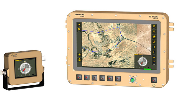
Designed for harsh environments and battlefield conditions, the CheetahNAV provides outstanding situational awareness, according to Etion Create. The crew of a light military vehicle can count on highly accurate position information, irrespective of whether they are denied satellite navigation. This is achieved through an advanced inertial measurement system (IMS), comprising several aids, including a gyro-compensated compass and an advanced Kalman filter-based algorithm.
“We are confident that the system provides dead-reckoning horizontal position accuracy of 0.2% of distance travelled in a GNSS denied situation,” said Jan Hurter, senior product manager. “This translates, by way of example, to accuracy of just 200 metres over a distance of 100 kilometers.”
The CheetahNAV can integrate with any number of different inertial navigation systems (INS) and can be aligned with any of the satellite navigation constellations. Combined with GNSS and compass information, the system enables dead-reckoning and accurate positioning of the vehicle in tactical situations. The tactical grade integral inertial measurement unit (IMU) ensures jamming-free operation.
Some of the guidance cues the system provides to the crew during tactical maneuvers include the vehicle’s current position, true heading and desired heading towards the next waypoint, current speed and desired speed to reach the next waypoint or destination on time, and the next waypoint or destination. It also shows the pitch and roll attitude of the vehicle and the track it has travelled.
This data is displayed on a sunlight-readable touch-screen enabled moving map display unit measuring 11.6-inch diagonal, in 16:9 TFT format, with a 1920×1080 resolution. Etion Create is also offering a slave unit for the vehicle driver, as the main display might be positioned elsewhere in a space constrained vehicle. This slave unit, measuring 3.5-inch diagonal TFT, displays information that is specifically required by the driver.
Significant benefits of the CheetahNAV system include ruggedness for extreme battlefield conditions and 28V or 12V DC operation in line with military standards. Moreover, it boasts a high operational reliability.
“It is important to note that Etion Create, as original design manufacturer, is focusing the CheetahNAV on the export market, including the possibility of technology transfer for indigenous manufacturing,” said Hurter. “Besides we offer a multi-language option, which is certainly a key advantage in multinational operations that are almost the norm nowadays.”
The CheetahNAV is non-ITAR controlled, which is the preference of most land forces around the world today to meet their battlefield management requirements.
Having utilized the building blocks of previously developed military off-the-shelf technologies, Etion Create considers the system to be at a high TRL (technology readiness level), and thus available for the export market.
Previously called Parsec, Etion Create is a South African original design manufacturer (ODM) with a long-standing international reach and a professional portfolio of technology offerings and experience across a wide range of business sectors, including defence and aerospace, information security, and mining and industrial sectors.
Tilt compensation to increase productivity for land surveyors
Trimble has introduced the Trimble R12i GNSS receiver, the latest addition to its GNSS portfolio. The Trimble R12i incorporates inertial measurement unit (IMU)-based tilt compensation using Trimble TIP technology, which enables points to be measured or staked out while the survey rod is tilted.
The tilt function is designed to empower land surveyors to focus on the job at hand and complete work faster and more accurately.
The IMU-based tilt compensation capability of the Trimble R12i builds on Trimble’s unrivaled ProPoint GNSS positioning engine, which delivers more than 30 percent better performance in challenging environments compared to the Trimble R10-2 receiver across a variety of factors, including time to achieve survey precision levels, position accuracy and measurement reliability.
Designed with flexible signal management that enables the use of all available GNSS constellations and signals, the Trimble ProPoint GNSS engine provides new levels of reliability and productivity.
Photo: Trimble
In addition, the ProPoint engine is a key enabler of the new TIP technology. Surveyors can continue to use the R12i’s tilt compensation functionality even in challenging environments when other solutions struggle to maintain GNSS and inertial positioning.
The Trimble TIP technology allows users to accurately mark and measure points in areas previously inaccessible for GNSS rovers such as building corners, or in hazardous situations, for example the edge of an open excavation. The receiver operates calibration-free out of the box and is resistant to magnetic interference from sources such as cars or electrical utility boxes.
The R12i also features real-time automatic inertial navigation system (INS) integrity monitoring. This system allows users to detect and correct for IMU biases introduced by use over time, temperature or physical shocks helping ensure measurement quality and integrity for the life of the receiver.
“The R12i represents Trimble’s dedication to perfecting the user experience with the industry’s best GNSS engine and now robust tilt compensation,” said Ron Bisio, senior vice president of Trimble Geospatial. “Trimble has been the leader in GNSS technology for more than 30 years and the R12i demonstrates our continued commitment to providing surveyors with the world’s most advanced and trusted GNSS systems.”
The Trimble R12i GNSS System is available now through Trimble’s Geospatial distribution channel.
A point cloud is fundamentally a simple construct. It is a collection of points in 3D space, each point being given a coordinate in Cartesian convention. The points can also be given other properties, often these will be indicative of how they were obtained.
Examples might include the time at which they were “seen” by the surveying device that collected the data. The intensity or error in position that the point has might also be included.
Often point clouds will have around 100 million points after conducting a survey. Photography can also be overlaid on point clouds using photogrammetry techniques to essentially build 3D photography.
Image: OxTS
INS survey: point clouds
The principal method of collecting point-cloud data is by using lidar. Lidar technology is akin to radar: light is sent out from the device and bounces back off of objects. The difference is that radio uses large wavelength radio waves and lidar uses small wavelength lasers for high precision.
The time for light to return to the device is used with the speed of light to calculate the distance away. Typically, a lidar device will contain lasers with a fixed vertical angle, but which spin around in the horizontal plane. Internally, the device knows at what angle the laser is pointing vertically and its azimuth angle. This gives the device the position of the point on the object in 3D spherical coordinates.
The lasers inside produce thousands of points per second. Intensity, mentioned above, refers to the intensity of the reflected beam and indicates the reflectivity of the object.
What is a georeferenced point cloud?
Lidar requires navigation data to conduct a survey. We combine the navigation data with the lidar data to create georeferenced point clouds. Lidar devices know where points are in relation to each other, but they need to be told where they are in the world to be able to build a point cloud while moving the lidar.
The navigation data often comes from an inertial navigation system (INS). An INS is a sophisticated combiner of inertial measurement unit (IMU) and GNSS data to get the best navigation data — so a device knows where it is in the world and how it is moving.
The coordinates from the INS are added vectorially to the point coordinates of the lidar to get the final coordinates that would be used in the point cloud. This allows a user to put their lidar device on a vehicle like a van or an unmanned aerial vehicle (UAV) with an INS, to survey large areas efficiently instead of doing multiple static surveys and stitching them together.
Photo: OxTS
What are point clouds used for?
There are a wide range of applications for which point clouds can be used. They are increasingly used in real time for robots and autonomous driving computers to understand their environment and navigate through it. The data in a point clouds is convenient for recognizing and identifying surfaces and objects; for example, other cars, road signs and lane markings.
OxTS has been a global leader in inertial and GNSS technologies since 1998. OxTS is fundamentally involved in helping car manufacturers get the navigation data they require to go with lidar data in autonomous vehicle development, and in point clouds creation for use in surveying.
Distances and volumes are easy to calculate using point-cloud analysis software, and intensity can help identify different materials.
Another feature that lidar offers is multi-returns. This allows a laser pulse (which has a finite cross-section) to bounce back off of multiple surfaces to give multiple points from the same pulse. This is particularly useful for seeing windows and also seeing through them, and also for a myriad of other uses such as seeing the top of a treeline and the ground when flying over with a UAV.
It can also be used to see snow depth. The lidar can see the top layer of snow and also gets another strong return from the ground beneath.
At OxTS, we see lidar point clouds being used for driverless-car and work-vehicle development, coastal and forest management, infrastructure monitoring (signs, drains, bridges, road surfaces, railroads, etc.), creating 3D models of cities, pipeline exploration and more.
The final product is a simple file format, for which the possibilities are almost endless — and we see new applications using point clouds all the time.
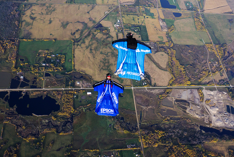
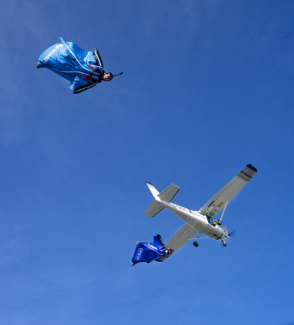
An applications engineer and his sky-jumping bud don wingsuits to test a NovAtel GNSS receiver integrated with an Epson IMU.
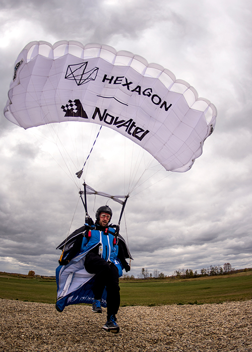
In September 2019, a specialized team assembled at an airstrip outside of Edmonton, Alberta, Canada. Their mission: Put the Hexagon | NovAtel PwrPak7D-E2 enclosed receiver through tricky test procedures that involved jumping out of an airplane at 10,000 feet.
Taking the NovAtel SPAN receiver to the skies was the brainchild of Andrew Levson, who is both a NovAtel engineer and a skydiving aficionado. He proposed using a wingsuit to test the receiver’s positioning accuracy.
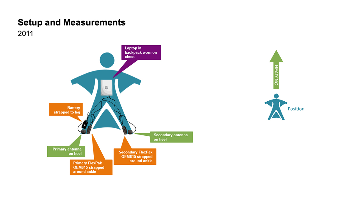
The first wingsuit dive took place in 2011, with NovAtel’s OEM615 receiver and ALIGN heading technology.
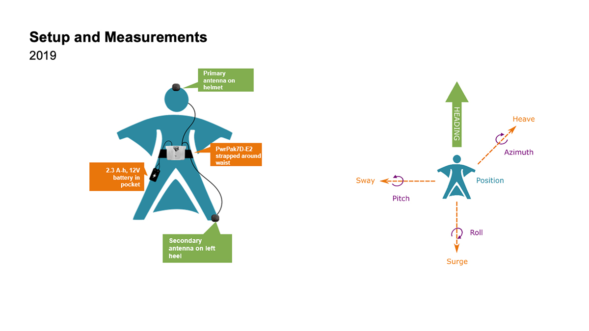
This time, the engineers aimed to test both NovAtel’s GNSS receiver featuring SPAN tightly coupled GNSS+INS functionality and its new companion, the Epson G370 inertial measurement unit (IMU). Both are packed in the PwrPak7D-E2 to provide uninterrupted positioning even in GNSS-denied environments.
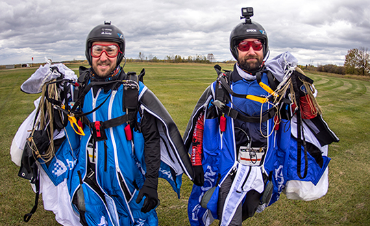
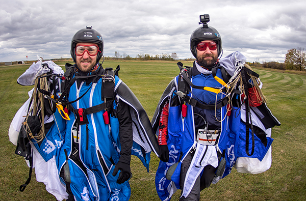
Wingsuit jumpers Andrew Levson (right) and Blair Egan suit up for the NovAtel tests. (Photo: NovAtel)
“We chose to revive the project, given that equipment has evolved with more comprehensive capabilities,” said Patrick Casiano, manager of Product Management and Applied Technology, NovAtel. “Between 2011 and 2019, we could significantly reduce the payload while increasing value in the data.” In 2011, NovAtel was only able to monitor Levson’s heading. In 2019, the team captured heading, azimuth, pitch and roll measurements.
“We wanted to prove that our equipment can work in a high-dynamic environment, which isn’t necessarily ideal conditions for collecting positioning data,” explained Kiera Fulton, associate product manager, Enclosures and Post-Processing Software, NovAtel. “By proving our products work in a less-than-ideal environment, we exemplify how robust our solutions are.”
Photo: NovAtel
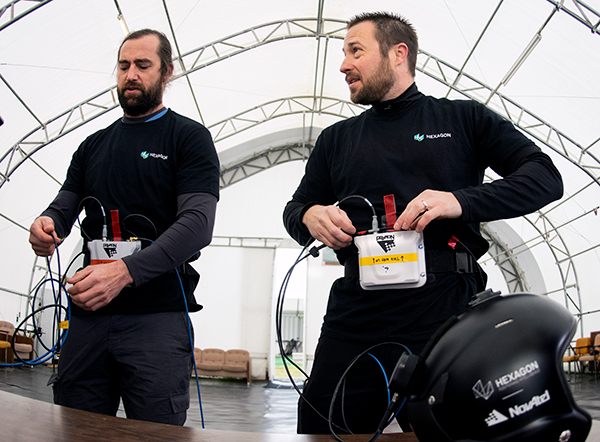
Test Preparation
For the 2019 test, the team chose to gather attitude data. The team also asked Levson to perform specific skydiving maneuvers to rigorously test the positioning solution. “Rather than performing just a simple flight to the ground, we wanted to challenge the solution to reveal more,” Casiano said.
The test was not easy to implement. A lot of behind-the-scenes planning and preparation went into the project. Plus, unforeseen factors made the test more challenging, Fulton said, such as logistics and weather.
“The skydivers require specific weather conditions in order to jump safely,” Fulton said. “Considering how quickly the weather can change here in Alberta, the time windows in which the skydivers could safely jump were few and far between. We pulled through regardless of these adversities.”
When the day of the jump came, the skydivers jumped five times — as many jumps as the weather would permit. “Theoretically, one jump is enough,” Casiano explained. “But as engineers, we always want to have more data to work with.”
2011 wingsuit jump setup. (Image: NovAtel)Wingsuit Jumps Compared: Because of the PwrPak7D-E2’s small size yet strong processing power, Levson required fewer devices in 2019 than in 2011, when he was equipped with two receivers, two antennas, a laptop and a battery. The amount of positioning data also increased. (Image: NovAtel)
High-Flying Maneuvers
The skydivers executed four maneuvers during their jumps.
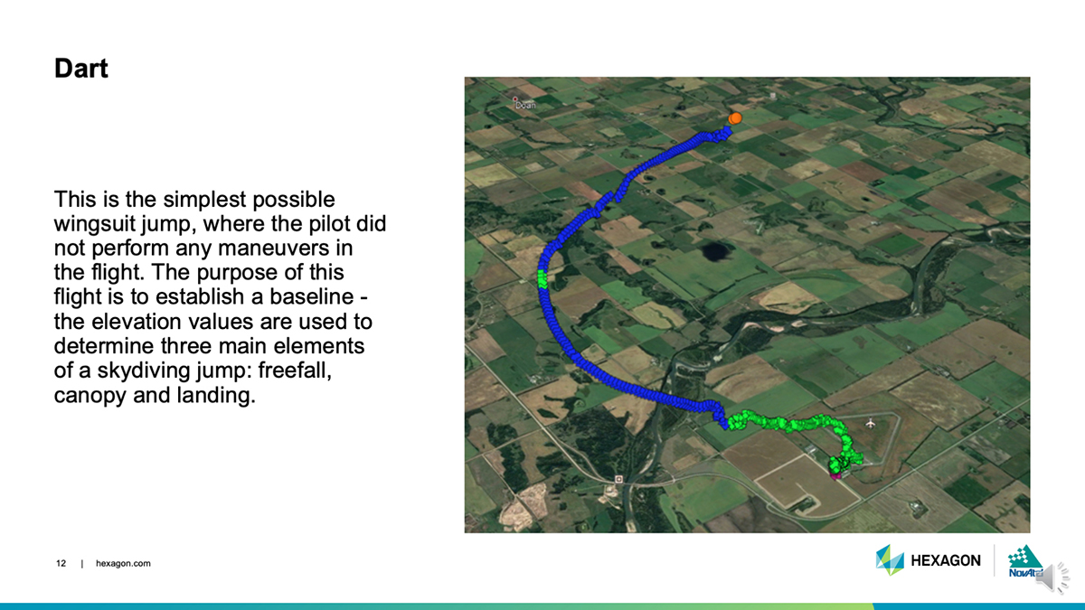
DART: This simple jump established a baseline for more complex maneuvers to follow. (Photo: NovAtel)
Dart. The skydivers first performed a straight jump, which the team called the Dart. The data from this jump provided a baseline for analyzing the positioning and attitude data.
“This was more important for the attitude analysis, as we have never collected inertial data in a skydiving jump before,” Fulton said.
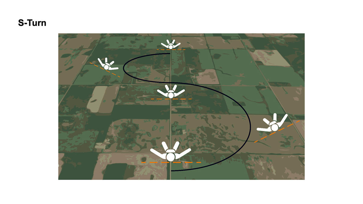
S-Turn: One of three completed maneuvers. (Image: NovAtel)
S-Turn. Next came the S-Turn. In this maneuver, Levson weaved from side-to-side to test how the equipment handles agile movements.
For the S-Turn, the engineers anticipated seeing the biggest changes in roll. “We were pleasantly surprised to see that the S-Turn is detectable in the azimuth data as well, indicating high correlation between roll and azimuth in a skydiver’s movements,” Fulton said.
The maneuver revealed that when Levson rolls, his body is using less surface area for wind resistance. As a result, he was falling to the ground faster, which then meant the dataset is shorter.
“This became another challenge during data processing, as the free-fall portion of the datasets were now becoming less than 3 minutes in duration,” Fulton said.
Data from the S-Turn also revealed the effect of crosswinds, which is detectable in the data.
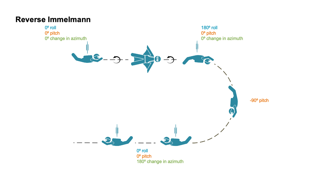
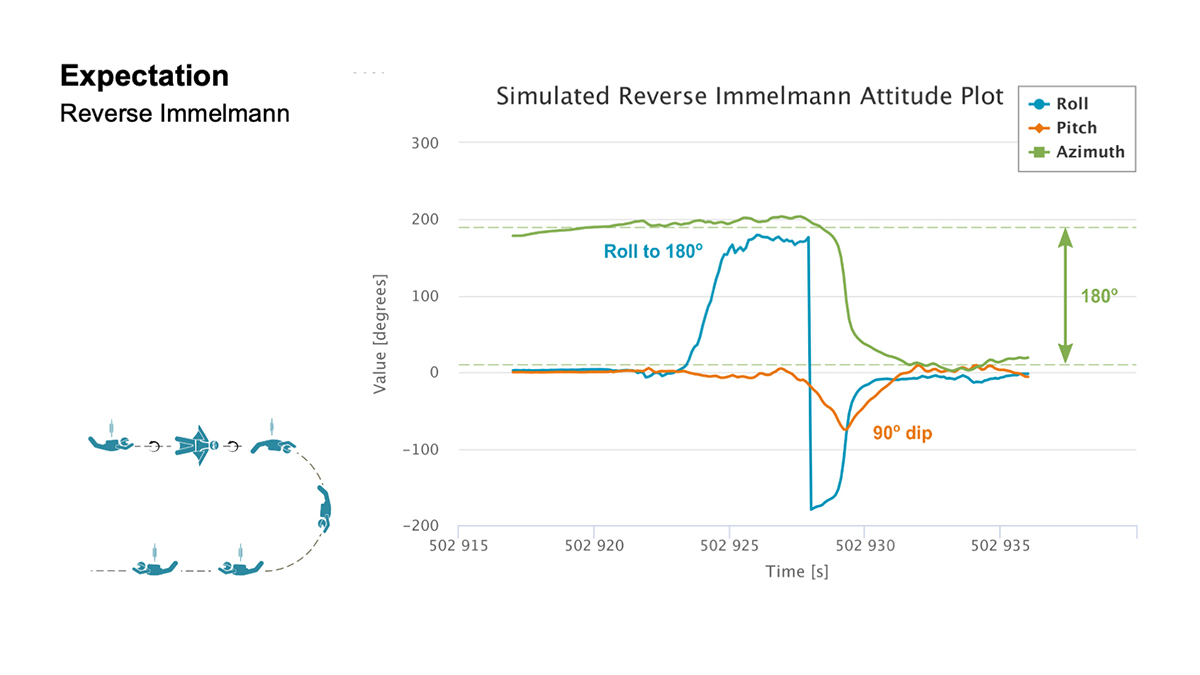
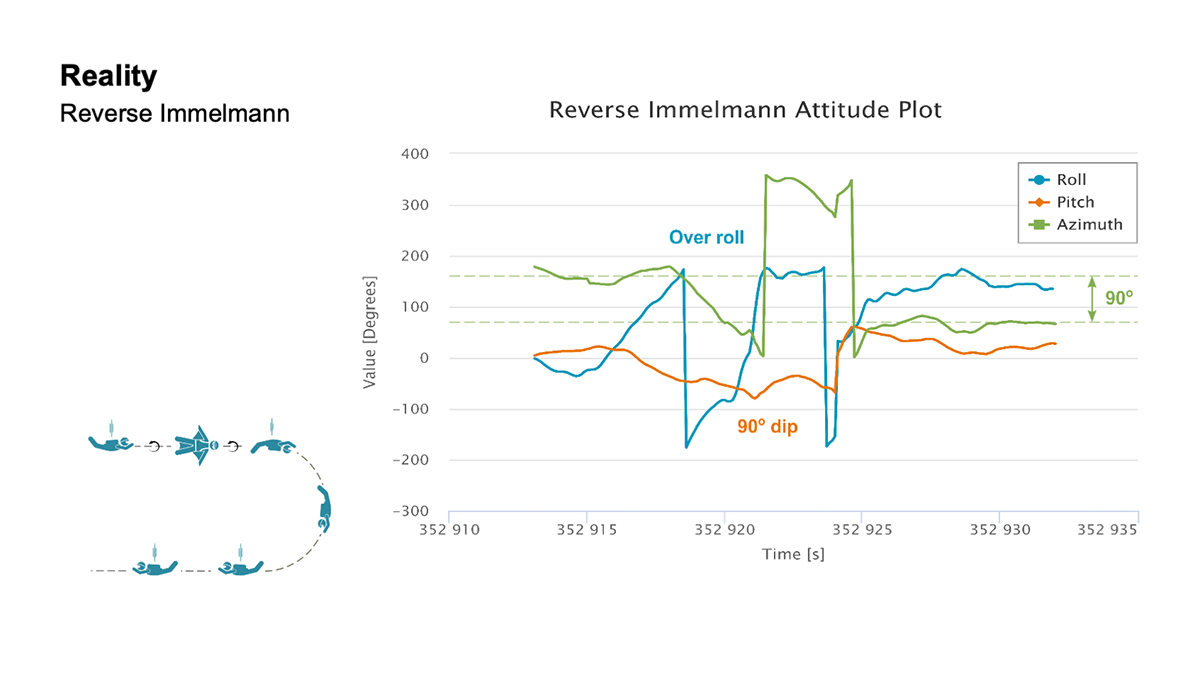
Reverse Immelmann: How the intricate maneuver works. (Image: NovAtel)
Reverse Immelmann. The third maneuver was the Reverse Immelmann. Levson flipped onto his back, began a downward turn until perpendicular to the ground, then leveled off, traveling in the opposite direction from where he began.
This complicated exercise provided data for all aspects of an attitude solution — roll, pitch and azimuth. By comparing the expected and real data, the team found several places where the maneuver wasn’t performed perfectly.
“There are many challenges once in the air that would have caused Levson to deviate from the trends in the data that we expected,” explained Fulton. “This is where we realized that our solution was working much more to evaluate the skydiver, rather than using the wingsuit to evaluate our product.”
Casiano agreed. “As a whole, the PwrPak7D-E2 was telling a story about Andrew’s flight,” he said.
The team also wanted to have the skydivers try a Cobra — a maneuver from aerobatics where an airplane momentarily lifts it nose and stalls — but time constraints prohibited it.
“If we had gotten this [a Cobra] recorded, it would have been detectable in the pitch and horizontal velocity data,” Fulton said. “Who knows what other findings we would have come across in this data!”
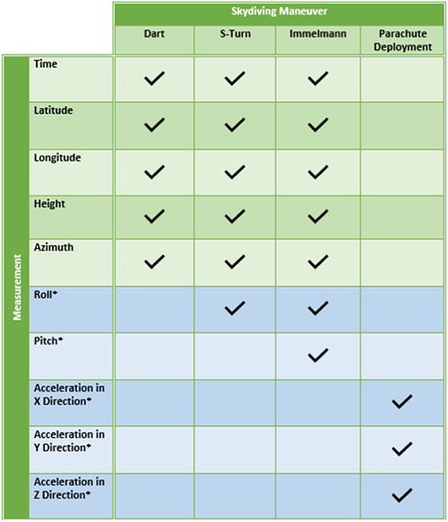
Measurement matrix: The asterisks (*) denote data values that can only be measured with an IMU. (Chart: NovAtel)
Applications
All these tests, of course, are designed to apply to real-world applications where the PwrPak7D-E2’s capabilities are used in dynamic environments.
For instance, an unmanned aerial vehicle (UAV) needs a feedback mechanism that tells the user whether it is moving or hovering. “In the wingsuit project, we proved that crosswind can be detected,” said Casiano. “This is an important finding for UAV applications, since a feedback loop from the PwrPak7 and the SPAN system can help rectify movement from external forces with counter propulsion to stay still. The PwrPak7D-E2 enclosures allow a data rate of up to 200 Hz, meaning you can capture motion with more detail.”
The PwrPak7D-E2 also works well for any black-box application where users want to record with the push of a button.
Inside the PwrPak7D-E2
Photo: NovAtel
The PwrPak7D-E2 is an all-in-one product. Its components are designed to work together seamlessly to provide positioning data, housed in NovAtel’s OEM7 firmware.
GNSS receiver card used to capture positioning data
Dual-antenna capability to provide accurate heading
Epson IMU to record attitude and motion
On-board logging to eliminate the need for constant monitoring on a PC
Post-Processing
Preparation enabled the team to process the data on site. The on-board logging feature on the PwrPak7D-E2 eliminated the need for constant monitoring during data collection. The unit is pre-configured so that at the time of the jump, Levson only needed to push a button for the unit to start collecting data.
Once the pair of skydivers landed, the ground team offloaded the data for processing, similar to using a memory stick, and moved it to a laptop computer.
“We pulled raw measurement data from the receiver and processed those measurements into position and attitude information,” Fulton said.
It took about 30 minutes to determine whether the dataset was viable. Later processing back in the office generated the charts such as those below.
Expectation: For both the S-Turn and Reverse Immelman maneuvers, a simulated plot was generated at the office to better understand the inertial data produced from the actual wingsuit jumps. (Chart: NovAtel)Reality: This chart shows the actual data. (Chart: NovAatel)
Dynamic Environments
Photo: NovAtel
The PwrPak7 series can be used in many environments in the automotive, agriculture, marine, defense and UAV fields.
“We are constantly trying to find ways to apply this product to other applications and industries,” Fulton said. “With more testing, we keep finding that the PwrPak7 can be used to solve more challenges.
“We want to push the boundaries of our products. True innovation comes from challenging yourself and hovering outside your comfort zone,” Fulton said. “For this project, we are more than satisfied with the results we found. In order to further challenge ourselves and this product, we look forward to applying the PwrPak7 in more scenarios.”
“The PwrPak7 is a robust unit that sets us up for more exploration,” Casiano said. “We are always looking for more challenges to put this unit through to see how the PwrPak7 can further help solve our customer’s problems.
But will there be more skydiving for NovAtel in Levson’s future?
“We could always revisit the skydiving project in another nine years,” Casiano said. “But who knows how the technology will evolve by then?”
Post flight: Blair Egan (right) and Andrew Levson back on Earth. (Photo: NovAtel)
What it feels like to take the plunge
For those of us who have never jumped out of a plane, engineer and skydiver Andrew Levson provides insight.
“It’s not as scary as people think. Because the plane is moving fast, it’s mostly just windy and loud. You don’t get that roller coaster type feeling; in fact you don’t feel like you are even falling — freefall feels more like floating than falling. You definitely wouldn’t know you are flying at speeds over 100 mph.
“When you are climbing out of a plane, there is nothing else on your mind aside from the jump you are about to do. It is pure freedom, and there is often no stress, just a sense of peace and an intense focus on your plan for the jump. Once you get out of the aircraft, you get to fly your body in the way that you want to — most people only know of the position of falling with your body arched and belly toward the ground, but there are many different ways you can orient your body. Some of the lesser known ways to fly your body include your arms and legs spread out while flying a wingsuit (with your belly or back toward the earth) or flying with your head pointing straight at the ground.
“When you skydive, you get to explore the sky with your friends, which is an amazing and unique experience. During a skydive, it is common to experience an ultra-focus during the jump — time slows down a bit and you can see and feel things that are seemingly beyond your typical capability.Many people are amazed at how much skydivers are able to do in the short period of time that a single skydive lasts — about a minute for regular skydives and about two or three minutes when flying a wingsuit.”
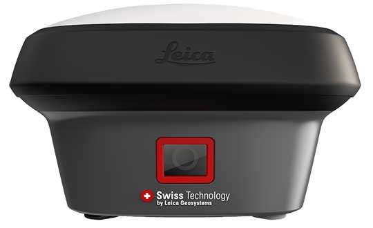
Hexagon AB has introduced the Leica GS18 I, a versatile, survey-grade GNSS RTK rover so powerful it enables surveyors to measure what they see, even structure in difficult-to-reach places, the company said.
It comes equipped with all the innovative functionality of the Leica GS18 T — Hexagon’s calibration-free, tilt-compensating GNSS solution immune to magnetic disturbances, plus the power of survey-grade visual positioning.
Through sensor fusion of GNSS, motion (IMU) and image (camera) technology, the Leica GS18 I enables the measurement of points from images. The ability to capture and measure sites via images goes far beyond the advantages of the GS18 T, which introduced the quick and convenient ability to measure points in spaces that cannot be measured with vertical poles, such as building corners, walls and points underneath obstacles (for instance, cars).
With the Leica GS18 I, professionals can now map areas that are difficult to reach physically, such as trenches, high power lines and busy roads, or blocked from GNSS signals, such as areas underneath bridges or canopies — safely and effortlessly from a distance.
“With the Leica GS18 I, mapping and surveying just got simpler, safer and more productive than ever before,” said Ola Rollén, Hexagon president and CEO. “The ability to quickly document an entire area of interest without the need to switch between tools or manoeuvre through obstacles frees up equipment and crews. Additionally, the simple and intuitive workflow of the Leica GS18 I brings the versatility of visual positioning to new user segments and applications — from utility service providers to crash scene investigators.”
The Leica GS18 I enables users to measure hundreds of points within minutes. Integration with Leica Captivate field software enables intuitive onsite point measurements and quality assurance from the field.
Further measurement of the captured images is supported by integration with Leica Infinity office software, which also enables the creation of automatically registered and referenced 3D point clouds from the images in standard export formats for use in a variety of point cloud software.
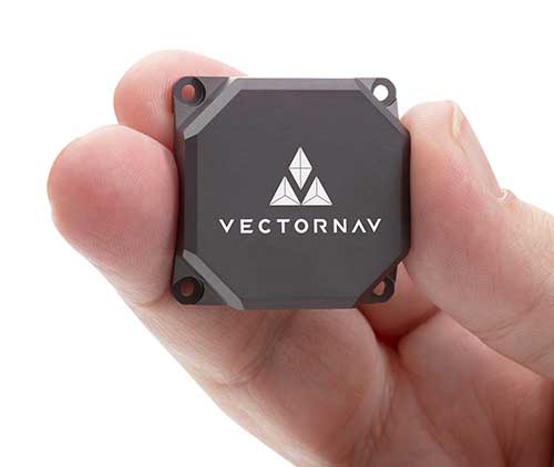
Tactical Embedded series of GNSS/IMUs. (Photo: VectorNav)
Embedded navigation company VectorNav Technologies has introduced a new line of inertial products: the VectorNav Tactical Embedded series of GNSS/IMUs.
Featuring a tactical-grade inertial measurement unit (IMU) and a multi-band GNSS receivers, the Tactical Embedded delivers milliradian attitude accuracy and centimeter-level positioning capability in a miniature 15-gram package.
VectorNav’s Tactical Embedded line is in a new smaller size, and enables cost reductions for a wide range of autonomous pointing and geo-referencing applications. These include gimballed intelligence, surveillance and reconnaissance (ISR), SATCOM systems, lidar mapping and photogrammetry, among many others.
The Tactical Embedded line supports external SAASM GPS for defense applications in ISR, electronic warfare, munitions and UAV navigation.
“The Tactical Embedded is the culmination of years of development to bring milliradian-level attitude performance and robust positioning into a form factor that represents a disruptive step in inertial navigation capability,” said VectorNav President John Brashear. “Systems integrators worldwide can now embed tactical-grade inertial navigation capabilities into their electronics, unlocking a range of new applications and possibilities.”
Designed and engineered at VectorNav’s AS9100-certified facility in Dallas, Texas, the Tactical Embedded line includes the VN-110E IMU/AHRS, the VN-210E GNSS-aided inertial navigation system (INS), and the VN-310E Dual Antenna GNSS/INS.
Highlights include:
0.05-0.1° heading; 0.015° pitch and roll
1 m horizontal and 1.5 m vertical position accuracy
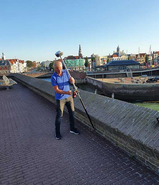
Empowered by a high-precision inertial measurement unit (IMU) on the Ultimate version, the Oscar from Tersus GNSS is a new generation of tilt survey receiver. Its calibration-free tilt compensation is immune to magnetic disturbances — holding the survey pole upright is no longer necessary. Powered by Tersus ExtremeRTK GNSS technology, Oscar can provide high accuracy and stable signal detection.
The built-in high-performance antenna can speed the time to first fix (TTFF) and improves anti-jamming performance. With a Nano-SIM card, Oscar can access the internet and transmit and receive correction data through 4G/Wi-Fi. The built-in UHF radio module supports long-distance communication. A detachable smart battery can display power levels. Two batteries support up to 16 hours of fieldwork in 4G/3G/2G-network and rover-radio mode. Oscar can be configured through a 1.54-inch interactive screen on the Ultimate and Advanced versions. The IP67-rated rugged housing protects it from harsh environments.
The Tersus Caster Service (TCS) helps surveyors set up a GNSS base station quickly to broadcast a correction stream via mobile networks. Natively supported by FieldGenius and Nuwa App, Oscar can be configured to different work modes to suit various daily jobs.
Satellite Tracking. Oscar supports multi-constellation and multi-frequency satellite tracking, including GPS, GLONASS, BeiDou, Galileo, SBAS and QZSS.
Accuracy. With enhanced positioning accuracy and constellation tracking, even in harsh environments, Oscar controls deviation within 3cm in surveying and mapping applications.
Quick Fix. Oscar can fix integer ambiguity rapidly after tracking satellites and receiving correction data: 3–5 seconds in the open sky, and 10–30 seconds under canopy or near buildings.
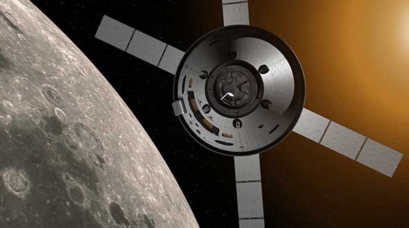
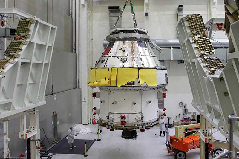
Honeywell, under a contract with Lockheed Martin, will supply guidance and navigation systems for NASA’s upcoming Artemis missions, which will fly humans to the moon for the first time since 1972.
The companies are supplying key components to NASA’s Orion spacecraft fleet for the Artemis missions. Components include the barometric altimeter, the inertial measurement system, and the GPS receiver.
Honeywell will provide 14 product types for Artemis missions III through V, including both hardware and software solutions, to support NASA’s lunar missions. NASA awarded Lockheed Martin a long-term, multibillion-dollar production contract for the Orion spacecraft, aimed to meet the space agency’s anticipated needs into the 2030s.
Working in collaboration with the Orion team over the next decade, Honeywell will support Lockheed Martin and its partners through the development and production of essential guidance and navigation systems, command data handling, and display and control products. The focus of the missions is to conduct science and learn lessons that will help take humans to Mars.
Honeywell will supply the following types of technology for the Artemis missions:
First Orion Spacecraft: In this March 30 photo, Orion I is moved to the Final Assembly and Systems Test cell at Kennedy Space Center. The spacecraft returned from Ohio after a successful series of environmental tests at Glenn Research Center’s Plum Brook Station. (Photo: NASA)
• Guidance and Navigation Systems. Key navigation and guidance solutions, including the barometric altimeter, which tracks the altitude of the Orion capsule in Earth’s atmosphere, as well as the inertial measurement system (INS) and GPS receiver, which track the position and movements of the capsule.
• Command Data Handling. Several data-handling products, including the vehicle management computer, which acts as the central computing platform supporting flight and vehicle control, as well as spacecraft communication functions.
• Displays and Controls. Three display units and struts, seven control panels, and two hand controllers used inside the spacecraft to help astronauts in the Orion capsule monitor and control the vehicle.
• Core Flight Software. Includes the integrated modular avionics software, a key system responsible for supporting maintenance functions sharing flight data information.
The contract to supply key components of the Orion crew module and service module is being managed and performed out of Honeywell’s facility in Clearwater, Florida. Work is also being conducted at the company’s facilities in Glendale, Arizona, and Puerto Rico.
Honeywell was part of NASA’s previous crewed space missions, including those that took humans to the moon.
Not just supporting players, alternative positioning, navigation and timing (PNT) systems strengthen, augment and — when needed — replace GNSS. GPS World explores how companies are using alternative PNT, and talks with John Fischer of Orolia about the company’s latest developments.
GPS World: What are Orolia’s latest advances and products regarding alternative PNT?
John Fischer: Regarding timing, which we have been doing for decades, our big alternatives to GNSS are internal atomic clocks and network-based timing, such as precision time protocol (PTP). Regarding positioning and navigation, the two areas on which we focus are IMUs and getting updates from GNSS, so that, when you lose GNSS momentarily, you have something on which to coast. The breakthroughs in MEMS technologies are astounding —they are getting better and cheaper every day. That shows wonderful promise.
The other area is doing satellite navigation using low Earth orbit (LEO) satellites, which are much closer to the Earth than GNSS ones and give you 30 dB or more of signal strength. We are focused the most on the Satellite Time and Location (STL) signal because it is available today. Supplementing your navigation system with updates from LEO satellites provides you some great non-GNSS navigation capability.
GPS World: The positions of LEO satellites are not monitored as closely as those of GPS satellites. Is that an issue?
JF: That is correct. You are losing accuracy by using what is available today because you do not know the positions of those satellites as well as you know those of the GNSS satellites and maybe you do not have the best geometry. All the GNSS satellites are in medium Earth orbit (MEO) because they have much better geometries for a small constellation. With just 24 satellites in MEO orbit, you get great geometries. When you go lower, you need an increasingly greater number of satellites.
The first generation of LEO satellites, the Iridium STL, are a much larger constellation, with 66 satellites, but still not enough to give you the good geometries. Today, you are getting less accuracy, but there are all kinds of new satellites being launched and the capability to track them will improve. We expect to be able to use signals from hundreds, if not thousands, of LEO satellites, so the geometry problem will start to go away and there are other things we can do to improve the accuracy. Meanwhile, we can get rather good performance with what we have today.
GPS World: What are some of your most recent advances, releases or products?
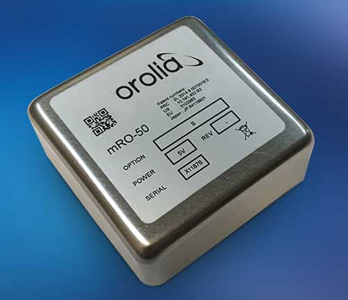
JF: On the timing side we have what we call a mini-Rubidium, the mRO-50, which we launched on June 4. Smaller, better, cheaper atomic clocks are coming out very soon.
GPS World: Do you have any comments on the recent executive order on resilient PNT?
JF: We coined the term “resilient PNT,” so we are glad to see it in use. We fully support those efforts.
GPS World: What about other alternative sources of PNT data, such as radar, lidar and signals of opportunity?
JF: Yes, they are that next level. Loran is ideal because it is so different from GNSS. When you are trying to design a reliable system, you want a lot of diversity, because if two systems have the same kinds of failure modes you have not gained in redundancy. Loran is literally at the other end of the spectrum from GNSS: It is a low-frequency microwave system. Instead of being space-based, it is land-based; instead of being low power, it is high power. However, there still are no stations up. It requires big equipment, so it will take some time.
When it comes to what you can do today, Loran does not contribute much. We support efforts to implement Loran very much, because we do need non-GNSS ways to make things resilient. Prior to GPS, we had to depend only on Loran. Today, with modern digital signal processing (DSP) techniques and receivers, I think we can expect the new Loran system to have much better accuracies than we had in the bad old days of the first generation of Loran.
The auto industry is doing a marvelous job of doing navigation using lidar or cameras. They are pretty much navigating driverless cars the way that humans drive, by just using visual cues. Those things have promise in certain unique areas.
Aceinna was recognized as a partner-level supplier for 2019 and was inducted into the Supplier Hall of Fame in the John Deere Achieving Excellence Program.
Aceinna is a supplier of high-performance inertial sensor modules to John Deere’s operation in Fargo, North Dakota, for autonomous navigation and positioning.
Hall of Fame status is given after a supplier attains a Partner-level rating for five consecutive years. The Partner-level status is Deere & Company’s highest supplier rating.
According to John Deere, “Aceinna has earned this award in recognition of its dedication to providing products and service of outstanding quality as well as its commitment to continuous improvement.” Company employees accepted the recognition during formal ceremonies held on Jan. 29 in Davenport, Iowa.
Suppliers who participate in the Achieving Excellence program are evaluated annually in several key performance categories, including quality, cost management, delivery, technical support and wavelength, which is a measure of responsiveness.
John Deere Supply Management created the program in 1991 to provide a supplier evaluation and feedback process that promotes continuous improvement.
“We are honored to be recognized by John Deere for our fifth straight year for the technical merits of our IMU (inertial measurement unit) and our focus on product quality and on time delivery,” said John Newton, vice president for inertial products. “This John Deere award further adds to the industry recognition that Aceinna has earned over the last couple of years, positioning us as one of the industry leaders and innovators in the autonomous vehicles navigation and positioning space.”
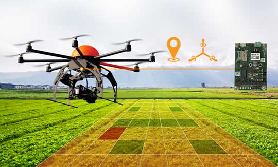
A new high-performance compact GPS/GNSS receiver with an on-board IMU sensor, tailored to the needs of UAV applications
Septentrio has released a new GNSS/INS receiver, the AsteRx-i D UAS. This multi-frequency receiver combines reliable centimeter-level positioning with 3D orientation, enabling automated navigation of aerial drones and robots.
GNSS signals received include the American GPS, European Galileo, Russian GLONASS, Chinese BeiDou, Japan’s QZSS and India’s NavIC.
With a high-performance IMU (inertial measurement unit) from Analog Devices integrated directly into the receiver board, AsteRx-i D UAS is compact and lightweight. Aboard the drone, its small form-factor combined with exceptionally low power consumption results in extended battery life and longer flight times.
“With this product we introduce into our inertial-GNSS portfolio an IMU which allows us to reduce the weight and power consumption of our UAS boards while making them easier to integrate. These are all key elements for a successful UAV platform.”
AsteRx-i D UAS is the first commercial product resulting from Septentrio’s collaboration with Analog Devices, delivering robust positioning and attitude (heading, pitch and roll) in demanding industrial environments. Both single-antenna and dual-antenna versions are available.
The single-antenna version provides a lightweight solution optimizing the system SWaP (size, weight and power). The dual-antenna version is designed for machines that need reliable heading directly from the start.
AsteRx-i D UAS comes with Septentrio’s Advanced Interference Mitigation (AIM+) technology. In aerial drones, where many electronics are crammed into a small space, neighboring devices can emit electromagnetic radiation, interfering with GNSS signals. AIM+ offers protection against such interference resulting in faster set-up times and robust continuous operation.
The on-board IMU from Analog Devices is exceptionally robust against mechanical vibrations. This IMU combined with Septentrio’s anti-shock LOCK+ technology makes AsteRx-i D UAS resilient against impact during takeoff and landing.
The AsteRx-i D UAS evaluation kit is now available in Septentrio’s online shop, which offers direct access to the company’s latest GNSS technology. For more information, contact [email protected].
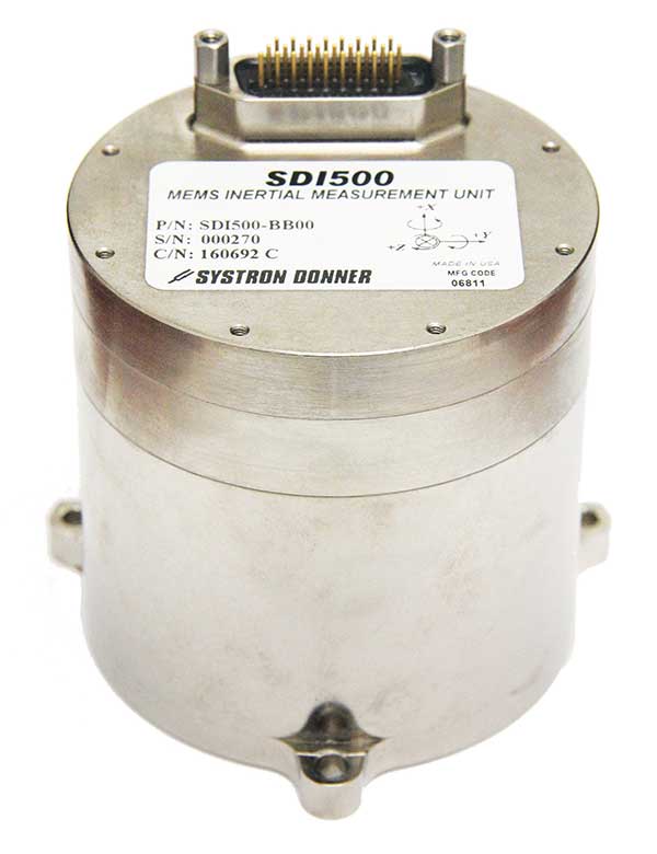
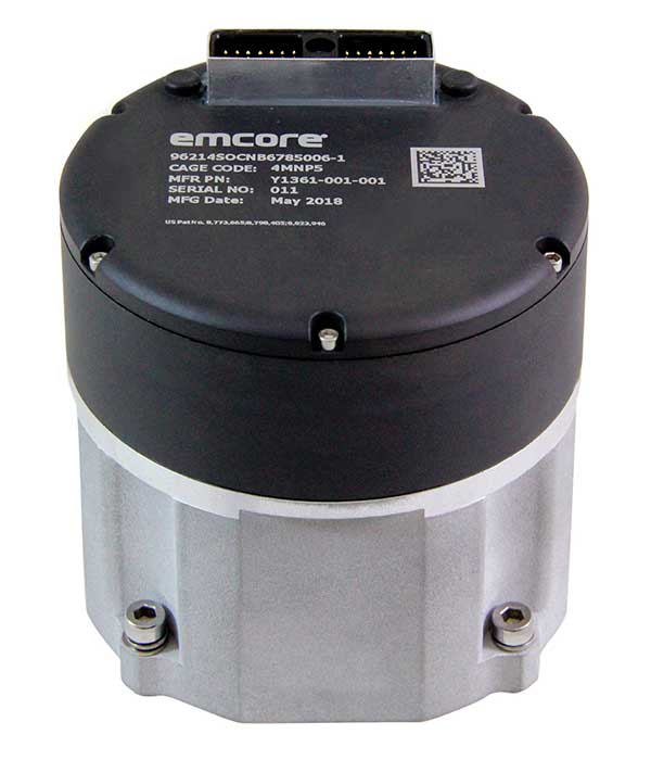
Emcore is offering two inertial measurement units (IMUs) suitable for the defense market.
SDI500 Tactical Grade IMU. Emcore’s Systron Donner Inertial SDI500 is a high-performance MEMS-based IMU that demonstrates true tactical grade performance with 1°/hour gyro bias and 1-mg accelerometer bias stability with very low 0.02°/hr angle random walk. Its performance is based on Emcore’s quartz MEMS inertial sensor technology. The SDI500 is designed to achieve the demanding performance levels required in sophisticated systems applications. Packaged in a highly miniaturized, cylindrical configuration with a volume of 19 cubic inches, it is suitable for use by integrators and OEMs.
The SDI500 is a compact IMU constructed with SDI’s next generation quartz gyros, quartz accelerometers, and high-speed signal processing that achieves tactical grade performance. The SDI500 IMU is rated for rugged military environments.
EN-300 Precision Fiber Optic IMU/INS. The EN-300 inertial system is designed to be compatible in form, fit and function with a legacy equivalent, but with the higher accuracy and performance needed for GPS-denied navigation, precise targeting and line-of-sight stabilization.
It features navigational-grade performance with 0.04°/hr gyro bias and 0.1-mg accelerometer bias stability with ultra-low 0.007°/hr angle random walk.
Internal signal processing provides full stand-alone or aided navigation, and as an option can provide standard IMU delta velocity and delta theta.