Fraunhofer IIS has opened paper submissions for The International Conference on Indoor Positioning and Indoor Navigation (IPIN) 2023, which takes place Sept. 25 -28 at the Nordostpark in Nuremberg, Germany.
The event is dedicated to indoor positioning, its applications and recent developments. The last decade has seen tremendous technical advances in indoor positioning. However, unlike the GNSS solutions established in the outdoor environment, there is not yet a technology that is affordable and accurate enough for the general market.
The potential applications of indoor localization are all-encompassing, from the home to vast public areas, from internet of things and personal devices, to monitoring applications.
The conference expects to attract up to 300 industrial and academic experts from the fields of computer science, electronics and surveying to address these challenges and the future of the industry.
To learn more about the conference and paper submissions, visit INIP-Confrence.org.
“Seen & Heard” is a monthly feature of GPS World magazine, traveling the world to capture interesting and unusual news stories involving the GNSS/PNT industry.
Ukrainian TV host Serhiy Prytula crowdfunded $20 million to buy Bayraktar drones for the nation’s defense against Russia. Baykar, a Turkish defense manufacturer, turned down the money and opted instead to donate three military drones to the country. The Turkish-made Bayraktar TB2 drone has been a key instrument used by the Ukrainian military to repel Russian forces, with the ongoing war the first major conflict in which the Bayraktar drones have been deployed.
Photo: Nicola Lercari, assistant professor of World Heritage, UC Merced
Arrested Decay
Scientists from the University of California (UC) Merced have mapped the fragile remains of Bodie, a Gold Rush ghost town. With harsh weather conditions, wildfires and earthquakes, only 10% of the original town is still intact. Researchers used a GeoSLAM handheld scanner to document more than 100 structures over four days. The scans preserve Bodie’s archaeological signature and enabled a 3D reconstruction of Bodie at its height in the 1870s.
Sea-level changes are critical to the island nation of Singapore. To help map ground deformation, researchers from the Earth Observatory of Singapore will access GNSS data collected by the Singapore Satellite Positioning Reference Network (SiReNT), along with a decade of archived GNSS data. SiReNT, an initiative of the Singapore Land Authority, produces precise positioning data with up to 3-cm accuracy. With four new coastal GNSS reference stations installed, EOS is beginning to study more accurate ways to measure deformation and climate effects.
A new indoor positioning system is helping hospitals and other healthcare facilities. PenguinIN connects to a facility’s Wi-Fi infrastructure to help staff track and locate key items, a task any nurses say takes an hour of every shift. In emergency rooms, it can track how long patients have waited and how long a physician has spent with each patient. Facilities also can use it to track air quality including dust, temperature and possible water leaks. PenguinIN applies advanced machine learning to establish the location of indoor objects, people and smartphones with up to 1-meter accuracy.
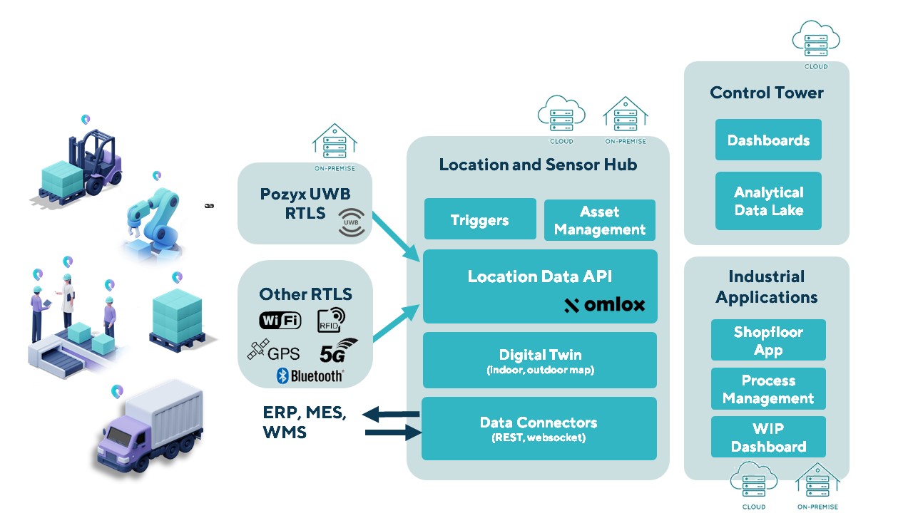
The Pozyx Platform is an asset tracking and identification solution for seamless indoor and outdoor tracking, based on the omlox hub and supporting multiple location technologies.
The omlox hub is an open standard for real-time location systems (RTLS) that combines location data from GPS, ultra-wideband, 5G, radio-frequency identification, Wi-Fi and Bluetooth.
The Pozyx Platform offers a seamless indoor/outdoor transition with zoom-in from a worldwide map to a detailed indoor map, showing highly accurate locations up to 10 cm. It is designed for smart manufacturing, providing a supply-chain solution that supports Industry 4.0.
It tracks and identifies any asset, providing real-time data to facilitate warehouse and inventory control, keep track of critical tools, and slash lost asset costs.
A “BeiDou positioning system for subways” began construction March 20 on the Beijing subway capital airport express line. The project will cover a 30-kilometer-long section of the express line, including five stations.
To provide positioning, the BeiDou Navigation Satellite System (BDS) will be combined with 5G for indoor positioning or in areas where the satellite signals are blocked.
The system will improve the positioning accuracy in subways to less than two meters, making it available for vehicle dispatching, passenger transport organization and emergency response. In addition, it allows passengers to use their phones to navigate and position in complex environments in subway stations through three-dimensional navigation.
“We will combine indoor and outdoor positioning in subways, that is, Beidou and its augmented reality technology will be used outdoors to achieve high-accuracy positioning, and indoor positioning technology integrated with 5G will be used to allow users to receive indoor positioning signals,” said Lin Luzhou, vice president of the GNSS and LBS Association of China.
The project is the largest indoor space navigation and positioning system in China, according to ECSN.com, and is expected to be finished within this year.
A roundup of recent products in the GNSS and inertial positioning industry from the February 2022 issue of GPS World magazine.
OEM
GNSS Receiver
For tracking, telematics
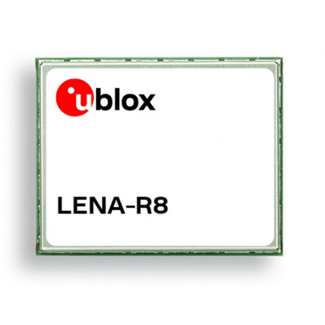
Photo: u-blox
The LENA-R8 GNSS receiver is based on the u-blox M10 platform. The compact module balances cost and performance with a single antenna and primarily targets customer deployments in the Europe, Middle East, Africa, Asia, and South America regions. Designed for tracking and telematics, the module series was designed to minimize material costs and data charges. The LENA-R8 supports a broad range of frequency bands with 2G fallback, providing maximum roaming coverage for global tracking applications using a single stock keeping unit (SKU).
The low-profile triple-band HC997EXF embedded helical GNSS antenna features eXtended Filtering (XF). It is designed for precise positioning, covering the GPS/QZSS-L1/L2/L5, GLONASS-G1/G2/G3, Galileo-E1/E5a/E5b, BeiDou-B1/B2/B2a, and NavIC-L5 frequency bands. It also covers regional satellite-based augmentation systems (WAAS, EGNOS, MSAS, GAGAN) and L-band correction services. It is packaged in a light (11 g), compact form factor (60 x 25 mm). Its precision-tuned, high-accuracy helical element provides an excellent axial ratio and operates without a ground plane, making it suitable for lightweight unmanned aerial vehicle (UAV) navigation and a wide variety of precision applications.
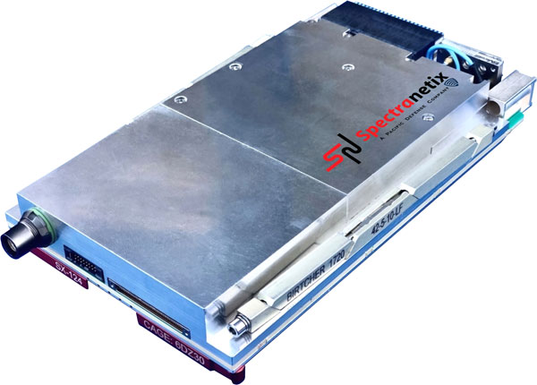
The SX-124 ruggedized 3U OpenVPX high-performance positioning, navigation and timing (PNT) card can provide timing and positioning information in a GPS-denied environment through sensor fusion. It is designed for highly integrated systems with a requirement for the U.S. Army’s C5ISR Modular Open Suite of Standards (CMOSS) and alignment with the Open Group Sensor Open Systems Architecture (SOSA) technical standard. The SX-124 can accept external sources or use its onboard GNSS receivers as reference inputs for timing and positioning data. The positioning data can be fused with internal and external inertial measurement units.
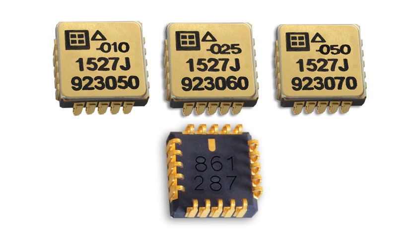
The Model 1527 series is a family of miniature, radiation-tested, tactical-grade micro-electromechanical (MEMS) accelerometers. Offered in three full-scale acceleration ranges — ±10 g, ±25 g and ±50 g — the series is designed to support a variety of critical space electronics testing requirements, including those of spacecraft, satellites and CubeSats. Their small bias and scale-factor temperature coefficients, excellent in-run bias stability and zero cross-coupling make the Model 1527 series particularly well-suited for spacecraft electronics testing applications requiring low power consumption (+5 VDC, 6.5 mA), low noise, long-term measurement stability in –55° C to +125° C environments, and performance reliability under intermittent radiation exposures.
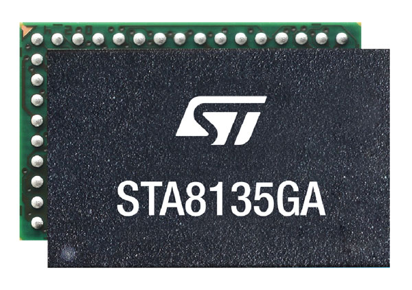
The STA8135GA automotive-qualified GNSS receiver is designed to deliver the high-quality position data needed by advanced driving systems. Part of the Teseo V family, the STA8135GA integrates a triple-band positioning measurement engine. It also provides standard multi-band position-velocity-time (PVT) and dead reckoning. The multi-constellation receiver delivers raw information for the host system to run any precise-positioning algorithm, such as PPP/RTK (precise point positioning/real-time kinematic). The receiver can track satellites in the GPS, GLONASS, BeiDou, Galileo, QZSS and NAVIC/IRNSS constellations.
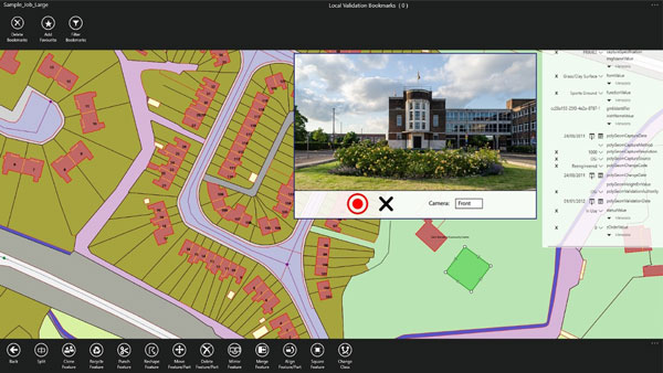
Survey application 1Edit now has increased support for photos and 2.5D data. 1Edit 3.1 allows users to attach feature photos, including automated geotagging, which enables surveyors to visualize assets and fine tune observations. Also included are new validation functions and improved handling for heights (2.5D data), typically useful for detailed asset and land-management surveys. Enhanced styling, including bitmap fills and dashed lines, make it easier to identify and classify different asset types during surveys. Additional control of editable layers and fields provides protection for non-editable data and protects the data quality. Significant improvements to rendering of thematic mapping enhances the speed and fluidity of the intuitive user interface.
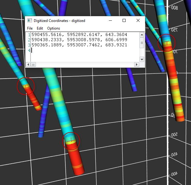
The latest version of Surfer surface mapping software has improved map-making functionality and data exporting capabilities. Surfer is used by more than 100,000 people worldwide, many involved in oil and gas exploration, environmental consulting, mining, engineering and geospatial projects. It provides fast and powerful contouring algorithms, enabling users to model data sets, apply an array of advanced analytics tools, and graphically communicate the results. Frames now have outlines and background fill colors to make them easier to read when placed on top of maps and attribute data can now be exported as numeric data.
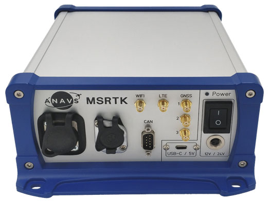
The Multi-Sensor (MS-) RTK/PPP device is a turnkey system easily integrated into surveying applications. The module includes up to three multi-frequency, multi-GNSS (GPS + Galileo + Glonass + BeiDou) receivers, a MEMS IMU, a barometer, a CAN interface for reception of vehicle data (wheel odometry and steering angle), and an LTE module for reception of RTK/PPP corrections. ANavS sensor fusion performs tight coupling of all sensor data with an Extended Kalman Filter (EKF). Various interfaces can connect additional sensors (such as camera or lidar) or output position information.
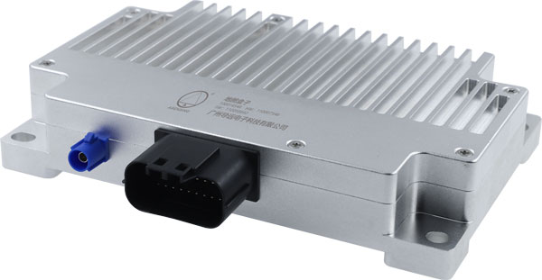
The HD-MapBox integrates high-precision map data based on high-precision positioning. Fusing data from a GNSS receiver, IMU, ADAS camera, vehicle dynamics and HD maps, the HD-MapBox can achieve a lateral error of less than 8 inches (0.2 meters) and a longitudinal error of less than 6.5 feet (2 meters) with a 95% confidence interval, providing an accurate reference for highway pilots and automated valet parking. Even if both GNSS and lane line detection are not available, the HD-MapBox can still enable vehicles to keep inside the lane for at least a quarter mile (400 meters).
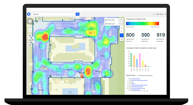
Esri ArcGIS IPS is an indoor positioning system that adds a blue dot to indoor maps, enabling users to locate their current position inside a building in the same way GPS enables outdoor location indicators. It uses an alternative technology to enable real-time positioning and navigation inside buildings. It also provides live location sharing and tracking, location data capture and analytical insights. ArcGIS IPS is available for users of ArcGIS Indoors, an indoor mapping system for smart building management, and ArcGIS Runtime SDKs, which enable the indoor positioning capability in custom-built apps.
Esri has released ArcGIS IPS, an indoor positioning system. ArcGIS IPS adds a blue dot to indoor maps, enabling users to locate their current position inside a building in the same way GPS enables outdoor location indicators.
ArcGIS IPS is designed to enable new use cases to improve on-site experiences, workplace operations and efficiencies. It uses an alternative technology to enable real-time positioning inside buildings that unlocks a variety of use cases, the company said.
Use cases inside buildings include:
real-time localization and positioning
real-time navigation and wayfinding
live location sharing and tracking
live location tracking
location data capture and analytical insights
real-time localization and positioning.
ArcGIS IPS is available for users of ArcGIS Indoors, an indoor mapping system for smart building management, and ArcGIS Runtime SDKs, which enables the indoor positioning capability in custom-built apps.
Image: Esri
ArcGIS IPS comes with the mobile ArcGIS IPS Setup app, which allows collection of radio signals from Bluetooth Low Energy (BLE) beacons inside buildings to enable an indoor positioning system. It can make use of an existing or new beacon infrastructure and is vendor agnostic.
ArcGIS IPS geoprocessing tools are also included to set up and author an IPS environment in ArcGIS Pro.
Users can navigate to specific points of interest — places, assets or people — in real time. This requires an existing app based on ArcGIS Runtime to support routable networks. ArcGIS Indoors can also display the route to a destination.
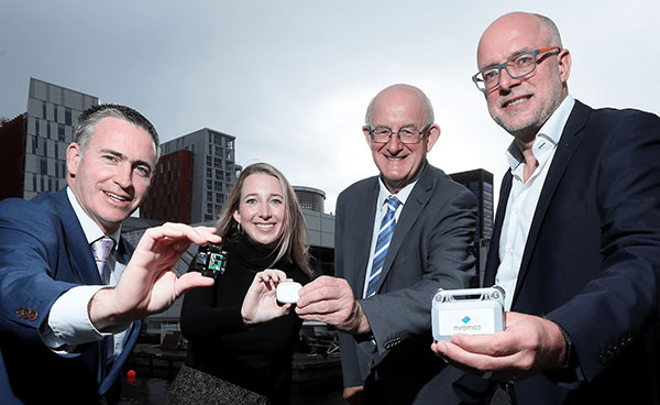
Danalto was visited by Ireland’s Minister Damien English upon the announcement of an ESA contract. (From left) English, Mary Kathryn Midgett (danalto), Tom Kelly (Enterprise Ireland) and David McDonald (danalto). (Photo: danalto)
Dublin-based danalto Ltd., has won a contract with the European Space Agency (ESA) to demonstrate low-infrastructure indoor location technologies that complement GNSS, particularly Galileo. ESA seeks to improve this European capability in order to enable impactful, societal use cases, thus prompting its call for this investigation, assessment, and demonstration by danalto.
Danalto is a internet of things (IoT) software company specializing in positioning and spatial intelligence technologies. It has extensive experience in positioning intelligence with its FiLo, a LoRa 2.4 GHz-enabled solution known for both its low power and low infrastructure requirements.
During the 18-month contract, danalto will determine the best positioning technology, system algorithms and deployment aspects across a range of location accuracies. This will be done by critically analyzing both classic (observables-based) and disruptive (signal-based) positioning techniques, culminating in a hybrid combination technology solution.
The resulting solution will support use cases across multiple industries — including healthcare, logistics and emergency services — and will accelerate the increased adoption of location positioning solutions within the European market and beyond. The trajectory of this project aligns with danalto’s progression plan for next generation positioning solutions, which will be brought to market for commercial use in 2022.
On Oct. 27, danalto was visited by Minister Damien English and Enterprise Ireland for a briefing on FiLo’s progress to date and plans moving forward aligned with ESA and beyond.
u-blox’s Bluetooth low-energy module features direction finding, bringing the benefits of high-precision positioning to indoor applications
U-blox, provider of positioning and wireless communication technologies, has announced the u-blox NINA-B4 Bluetooth low-energy module series. Based on Nordic Semiconductor’s recently announced nRF52833 chip, NINA-B4 enables a number of Bluetooth features including Bluetooth long range, Bluetooth mesh and Bluetooth direction finding.
The module is tailored to the needs of applications in the connected industry, smart homes, buildings and cities, asset tracking and eHealth.
The NINA-B4 offers a new direction-finding feature, a key component of the Bluetooth v5.1 specification that brings the benefits of high-precision positioning to indoor applications. It is the first u-blox module designed to act as both a transmitter and a receiver in angle of arrival (AoA) and angle of departure (AoD) direction finding and indoor positioning applications.
In AoA-based implementations, stationary beacons equipped with multi-antenna arrays determine the angle of arrival of signals emitted by a tracking device to pinpoint the tracker’s location with sub-meter-level accuracy. When AoD is used, the tracking device triangulates its position by calculating the angle of departure of signals from the stationary Bluetooth beacons’ multi-antenna arrays.
Mesh, long range, and extended temperature range
The u-blox NINA-B4 enables wireless mesh networks, which offer robust communication between large numbers of connected devices, extending the reach of messages by relaying them from node to node until they reach their destination. By simplifying the control of groups of devices, mesh networks are well suited for applications such as smart lighting systems in cities and buildings, which further benefit from the module’s enhanced operating temperature range (up to 105 °C).
Featuring Bluetooth long range, the NINA-B4 series can be deployed in harsh environments, for instance, to enable wirelessly connected and configurable equipment. Long range not only increases the distance that Bluetooth signals can travel in undisturbed environments, but also makes communications more robust and reliable in unfavorable ones, a common need in production plants or on factory floors.
The NINA-B4 series comes with u-blox u‑connect software, simplifying integration of Bluetooth into new and existing products by providing an easy-to-use interface to configure the connectivity required.
NINA-B4 has a powerful Arm Cortex-M4F MCU with an open CPU architecture, allowing customers to run their own applications on the module. Supporting Zigbee and Thread, the first members of the NINA-B4 family come with an internal PCB antenna, or alternatively with a U.FL connector for an external antenna of choice.
Samples of the NINA-B4 will be available in December.
Racelogic’s Julian Thomas describes and demos the company’s VBOX indoor positioning system at ION GNSS+ 2018, which took place Sept. 24-28 in Miami. According to the company, the solution is designed to provide accurate position and velocity in the absence of GNSS signals.
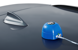
VBOX indoor positioning beacon atop a car. (Photo: Racelogic)
Racelogic demonstrated a new VBOX solution for accurate position and velocity in the absence of any GNSS signals, such as indoors, at the ION GNSS+ exhibition.
VBOX data acquisition systems are used for measuring the speed and position of a moving vehicle. Based on a range of high-performance GPS receivers, VBOX dataloggers can record high-accuracy GPS speed measurements, distance, acceleration, braking distance, heading, slip angle, lap times, position, cornering forces and more.
VBOX indoor positioning beacon in a bracket. (Photo: Racelogic)
The new VBOX Indoor Positioning System consists of a network of fixed beacons communicating with a small receiver mounted on the roof of the vehicle, which is connected to an existing VBOX. The receiver computes its position 100 times a second to around 5 centimeters real-mean-squared (RMS) accuracy. The system can be used on its own or with an internal inertial measurement unit (IMU) to improve the velocity accuracy.
Racelogic engineers worked closely with its VBOX customers to develop a solution that allows the same test equipment and software that has traditionally been limited to outdoor use to be used anywhere that satellites coverage is limited or completely unavailable, such as in a parking garage.
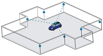
Beacon placement. (Image: Racelogic)
The VBOX seamlessly switches between outdoors and indoors, allowing testing to continue whatever the environment and VBOX users to make use of their original hardware and software applications.
Racelogic will demonstrate the system at the ION GNSS+ exhibition at the Hyatt Regency in Miami, Sept. 26-27. Racelogic will also be showcasing its new, upgraded version of SatGen simulation software for the Labsat 3 Wideband simulator.
UWB is being used in a novel microwave imaging and localization system, one which features Antonio Vivaldi’s namesake antenna.
By Fengzhou Wang and Guohua Wang
INNOVATION INSIGHTS with Richard Langley
VIVALDI. No, you aren’t reading an article in Gramophone. This happens to be the name of a particular kind of broadband antenna, which is particularly useful at microwave frequencies and for ultra-wideband (UWB) applications in particular. It was invented by the British electrical engineer Peter J. Gibson in 1978 while working at Philips Research Laboratories. In a 1979 conference paper entitled “The Vivaldi Aerial,” Gibson described it as “a new member of the class of aperiodic continuously scaled antenna structures and, as such, it has theoretically unlimited instantaneous frequency bandwidth.” He went on to say “This aerial has significant gain and linear polarisation and can be made to conform to a constant gain vs. frequency performance. One such design has been made with approximately 10 dBI gain and -20 dB sidelobe level over an instantaneous frequency bandwidth extending from below 2 GHz to above 40 GHz.” Broadband indeed!
So why did Gibson name the innovative antenna “the Vivaldi aerial”? It has to do with its shape. Another term for the Vivaldi antenna (sometimes called the Vivaldi notch antenna) is the tapered slot antenna. The planar antenna, constructed out of thin metal sheet or printed circuit board (PCB), features a slot line gap cut out of the sheet or etched from the PCB, which gradually flares in the direction of wave propagation (see Figure 1 in this month’s article to see what a Vivaldi antenna actually looks like). Since the spacing of the gap is related to the wavelength of the radio waves that can be launched, the antenna can be used over a wide frequency range not unlike the log-periodic antenna used in shortwave broadcasting or the biconical antenna and its butterfly antenna subtype used for UHF TV reception. Of course, according to the reciprocity theorem, an antenna designed to transmit radio waves can generally be used to receive radio waves with the same antenna properties (gain, bandwidth and so on).
But let’s get back to the tapered slot antenna’s formal name. According to one his co-workers, the shape of the antenna reminded Gibson (who was also a musician and composer) of the cross-section of an early trumpet. So he named his antenna after Antonio Vivaldi, the famous baroque music composer, who wrote several concertos featuring trumpets. And 1978, the year of the antenna’s invention, was the three-hundredth anniversary of Vivaldi’s birth. It doesn’t hurt that the shape of the slot also looks a bit like a cursive “V” when the antenna is stood on its end.
While the basic Vivaldi antenna generates (or receives) linearly polarized waves, it is possible to combine two elements at right angles to generate (or receive) circularly polarized waves.
Because of its broadband characteristics and ease of PCB manufacturing, the Vivaldi antenna has been used extensively in UWB applications. Conventional radio transmissions use a variety of modulation techniques but most involve varying the amplitude, frequency and/or phase of a sinusoidal carrier wave. But in the late 1960s, it was shown that one could generate a signal as a sequence of very short pulses, which results in the signal energy being spread over a large part of the radio spectrum. Initially called pulse radio, the technique has become known as impulse radio ultra-wideband or just ultra-wideband for short. The bandwidths of UWB signals are quite large. For example, in the U.S., current Federal Communications Commission rules for pulse-based positioning or localization implementations require the applied bandwidth to be between 3.1 and 10.6 GHz and the bandwidth to be greater than 500 MHz or the fractional bandwidth to be more than 0.2.
The use of large transmission bandwidths offers a number of benefits, including accurate ranging and that application in particular is being actively developed for positioning and navigation in environments that are challenging to GNSS such as indoors and built-up areas.
In this month’s column, we learn how UWB is being used in a novel microwave imaging and localization system, one which features Antonio Vivaldi’s namesake antenna.
Indoor localization is challenging work using traditional location-based services such as GPS. Approaches for indoor position estimation have used radio-frequency (RF) signals including narrowband signals such as Wi-Fi and Bluetooth. Impulse radio ultra-wideband (UWB) signals have also been widely investigated. Compared with narrowband signals, UWB signals provide high signal-to-noise ratio, which helps to provide an accurate estimate of signal arrival time for time-based location algorithms such as time of arrival (TOA). Furthermore, UWB signals provide larger coverage areas and a ranging capability. Sub-millimeter positioning accuracy is achievable. And UWB-based location has an inherent high time resolution making it useful in a tracking system for medical and other applications.
A number of investigations in UWB positioning have already been carried out, with several relatively expensive commercial UWB kits available from companies such DecaWave and BeSpoon. But additional work still needs to be carried out to fully evaluate the UWB solution, so this is still an open research topic. One problem area requiring further investigation is positioning in the non-line-of-sight (NLOS) environment. This is considered the main challenge for UWB location, since it is associated with strong fading due to reflection and diffraction from various obstructions such as furniture in the room. Various threshold crossing methods using techniques of energy detection, correlation and the multiple signal classification (MUSIC) spectral analysis algorithm have been used to resolve the multipath propagation problem in NLOS environments. However, these approaches require complicated signal processing, which increases the computing cost.
Moreover, UWB technology is also being widely introduced in microwave imaging for military and biological applications. It provides high-precision detection and high-resolution images, depending, in part, on the operating frequency range. The radar-based microwave imaging or MWI is a time-domain confocal imaging method that aims to indicate the position of the targets by use of the delay time of the reflected signal. MWI technology highlights the target from the testing environment by using different values of the dielectric permittivity constant.
In this article, we propose a hybrid method combining MWI and localization of body-worn UWB antennas for improving the accuracy of indoor positioning. The proposed system will be able to differentiate an LOS environment from an NLOS environment using MWI detection ability, and then adjust the scanning antenna array setup using robotic support. Furthermore, we introduce a threshold value in the filter function to highlight major obstructions in an NLOS environment such as a physical item. Using this proposed system for TOA measurements, we have obtained an overall average accuracy in two-dimensional localization of around 1.7 to 2.5 centimeters.
SYSTEM EXPERIMENTAL SETUP
We have developed a robotic antenna array for indoor microwave imaging to assist in indoor location with wearable antennas. The basic architecture of the proposed UWB localization system consists of two components: tag antennas and anchor antennas. Two thin-film tag antennas are worn on both shoulders of a human, and seven wideband Vivaldi antennas (also known as tapered slot antennas), acting as anchor antennas, are mounted on individual robotic supports, which can adjust the height and the rotation angle of each antenna. All the antennas are fabricated with printed-circuit board (PCB) material to reduce the cost.
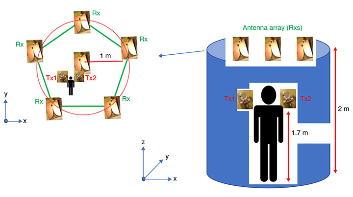
FIGURE 1. UWB antennas setup for the proposed location approach.
In FIGURE 1, the Vivaldi antennas are shown with blue dots and are placed on the top of the robotic support 2 meters above the ground. The antenna array covers a scanning area with a radius of 2 meters. The two compact wearable tag antennas are placed on the left and right shoulders of the target human at a nominal height of 1.7 meters.
Other main components of the proposed system are shown in FIGURE 2.
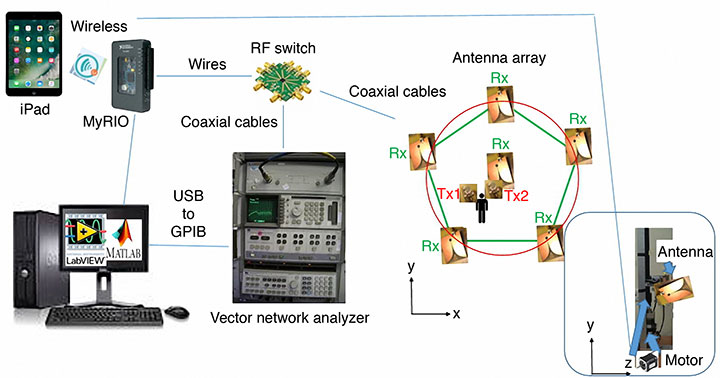
FIGURE 2. The proposed system diagram.
The system can be manually controlled by an Apple iPad or automatically controlled by a personal computer (PC). The PC runs the National Instruments (NI) Laboratory Virtual Instrument Engineering Workbench (LabVIEW) programming environment and an NI instrument monitor for debugging the operating process. Further information processing is carried out by combining the received signal from a vector network analyzer (VNA) though the USB-based NI-DAQmx driver software and associated cable and a mobile device such as the Apple iPad for remote control and cloud access. Two ports of the VNA are connected to an RF switch to transmit and receive signals using the antennas located in the scanning area. During the detection phase, the anchor antennas are sequentially active, and a number of signal time series are transferred back to the PC for imaging processing. The delay-and-sum algorithm is used for signal processing and imaging reconstruction in Matlab to find the position of any obstruction in the scanning area.
The following specific components were used in the experimental setup shown in Figure 2: an Agilent HP 8510B VNA (operating from DC to 20 GHz for two-channel acquisition), a single-pole eight-throw (SP8T) switch (an Analog Devices HMC321LP4 on an evaluation PCB forming a switchboard), seven directional UWB Vivaldi receiving antennas (operating from 2 to 14 GHz); two body-worn UWB transmitting thin-film antennas (operating from 3 to 9 GHz), a reconfigurable input/output device based on a field-programmable gate array (FPGA) and a microprocessor (NI myRIO-1950 board), a general-purpose interface bus (GPIB) to USB cable (Agilent 82357B), and a personal computer running LabVIEW and Matlab.
PRINCIPLES OF OPERATION
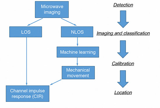
In our proposed technique, the range-based TOA approach is implemented, making use of the high accuracy obtained by the fine time resolution of the applied UWB impulse signal. FIGURE 3 shows a flowchart of the proposed localization scheme in our approach. Initially, the system needs to be calibrated to normalize the responses of all the antennas in the anchor antenna array and to eliminate the effect of reflections from the environment. To calibrate the system for microwave imaging, no objects should be present in the scanning area at this stage.
FIGURE 3. Proposed scheme for UWB localization in realistic environments with multipath situations.
There are four main phases of the operation. Firstly, the radar-based UWB microwave imaging system is introduced into the localization system to classify the LOS and NLOS environments. If the environment is LOS, the system will go to the location phase directly. If the environment is NLOS, further operations for the antenna array configuration need to be carried out to reduce the multipath effect from the non-target object. In this case, the only located target is the pair of wearable tag antennas.
Secondly, the system moves to the imaging and classification phase involving the Vivaldi antenna array on the anchor station. Using UWB impulses for MWI, the imaging system can detect the existence of inhomogeneity within a structure or medium and a two-dimensional (2D) image can be developed as shown in FIGURE 4.
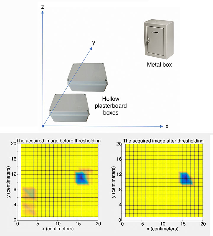
FIGURE 4. (Top) Layout of test setup. (Bottom left) The acquired imaging on shoulder plane before thresholding. (Bottom right) After thresholding.
During the imaging process, one wearable antenna is transmitting a Gaussian pulse while the other is receiving the scattered signals. Circular synthetic aperture radar (CSAR) and elevation-CSAR (E-CSAR) are widely used approaches to extract 2D spatial information of the imaging scenario and have been used for small area 2D remote sensing and foliage target detection. For our current work, we have adopted the CSAR approach. We developed Matlab code to process the data and generate images.
Various material obstructions such as hollow plasterboard boxes, solid concrete items and metal boxes were investigated during our experiments. We had to define threshold values for the various materials to get a more visually acceptable image.
According to the experiments, metal has a significant effect in NLOS environments, and the threshold value was used to optimize the final imaging result (a 20-pixel by 20-pixel image). The scanned area could be visualized with the imaging results depending, in part, on the heights of the antennas on the anchor station and the threshold value used. In this case, two hollow plasterboard boxes are filtered out, leaving the metal box in the image as shown in Figure 4(c).
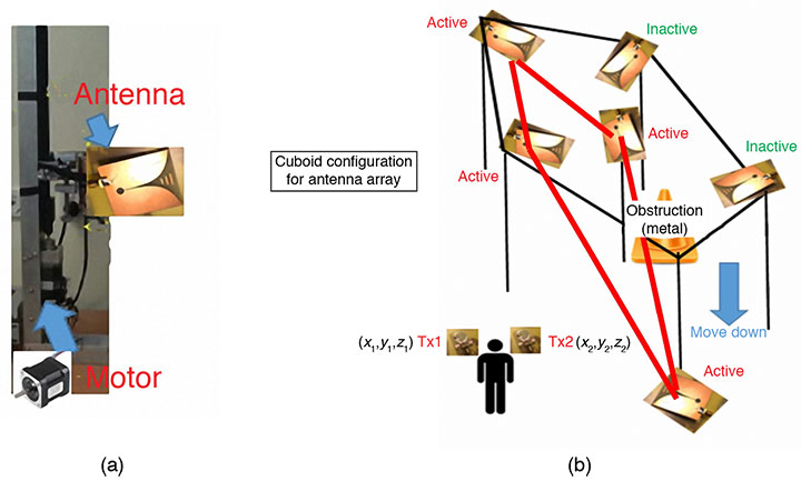
In the third phase of the operation, the image result is fed into the machine learning algorithm used in the calibration phase. A pre-defined geometry of the antennas on the anchor stations, such as the six anchor stations in a cuboid shape, Y-shape or L-shape, was chosen for implementation in the current environment. The height and angle of the anchor antenna array pattern were adjusted using motors controlled by the NI MyRIO board. In this scenario, all the antennas on the anchor station are receivers (Rxs), and only body-worn antennas are transmitters (Txs).
In this particular experiment, the obstruction (the metal box) is detected on the right upper side of the scanning area, so the cuboid configuration was selected as the anchor station setup. Four antennas on the left of the area were selected as receiving antennas as shown in FIGURE 5. Figure 5(a) highlights one of the antennas.
FIGURE 5. (a) Setup of anchor station. (b) Pre-defined geometry setup for anchor stations used for the experiment of Figure 4.
Finally, in the fourth (location) phase, the time of arrival of the signal from the transmitting antenna array at the receiving wearable antenna is estimated by channel impulse response (CIR) and peak detection techniques. An inverse fast Fourier transform (IFFT) is then applied to obtain the impulse response of the measured channels. The channel impulse response is given by:
where δ is the Dirac delta function, K is the number of resolvable multipath components, τk are the delays of the multipath components, ak are the path amplitude values, and θk are the path phase values. The MyRIO board controls the RF switch to circulate each receiving antenna and the corresponding S-parameter value (S21) is passed through the GPIB-to-USB cable for storage in the personal computer. The CIR, a peak detection technique and a TOA data-fusion method are used to accurately estimate the target’s location (xm, ym). Let (xi, yi) represent the position of the ith transmitting antennas, and r represent the range value obtained from the TOA measurement:
RESULTS
Let us summarize the procedure we followed for an experimental test of our proposed approach as described in the previous section. Our hardware setup is shown in Figure 1, and we carried out the experiment to demonstrate performance in both LOS and NLOS environments. Firstly, a 2D image of the scene area was reconstructed using the time-varying backscattered intensities as shown in Figure 4.
Secondly, the image is processed based on a database to detect the dielectric constants of the obstructions. The shape of the obstruction might not be completely delineated as the low resolution of the image favors an increased efficiency of the imaging processing. However, the position of the obstruction can be found whether it is on a critical path or not. Thirdly, the proper archor-station setup is implemented using the MyRIO board to control the RF switch and antenna motors according to a pre-defined database in the personal computer. Lastly, the peak detection algorithm is used to estimate the TOA of the UWB signal from the Tx at the Rx. The TOA is directly estimated by the detection of the strongest peak of the CIR.
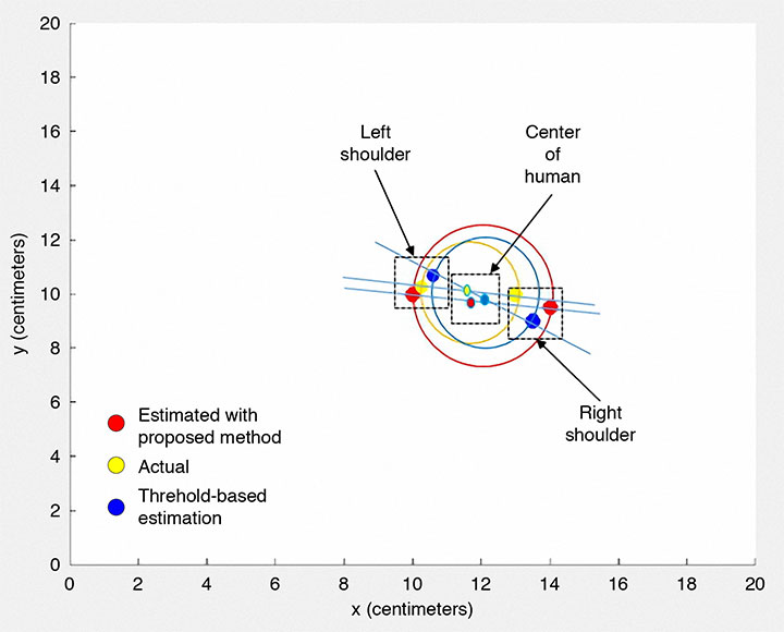
FIGURE 6 shows the localization results for the situation in Figure 4. The same experimental method was repeated but using a threshold-based TOA estimation procedure, and the results compared with our procedure. The results using that approach are also displayed in Figure 6.
FIGURE 6. UWB localization: estimated and actual positions of the antennas placed on the body for the environment as shown in Figure 5.
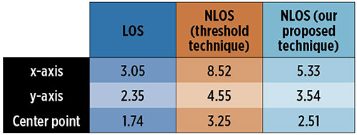
In TABLE 1, we summarize the localization errors obtained in the different environments using the two estimation techniques. The average accuracy achieved for our proposed approach for a single antenna is in the range of 3 to 5 centimeters. Given that there are two sensing antennas, one on each shoulder, we could establish a middle point as the position of the human body, and combining the results of each antenna, we could improve the accuracy to about 2.5 centimeters in the NLOS environment.
TABLE 1. Average localization error in centimeters for different testing environments with different estimation methods.
The method accuracy depends on the pre-defined solution for the anchor antenna array in the NLOS environment, and the estimation accuracy could be improved by training the hardware during the operating period. Furthermore, the localization accuracy also can be enhanced by increasing the number of active anchor stations. However, this will cost more in terms of hardware implementation and also require more space for the apparatus.
CONCLUSIONS
This article presents a hybrid UWB technique combining radar-based microwave imaging and localization of a body-worn UWB antenna for mapping 2D environments. We provided an overview of the concept and method of detecting obstructions, and described a sample implementation that proved the concept and provides ideas for further improvements.
Our results demonstrate the usefulness of the proposed technique, which provides similar performance regarding computational load and accuracy compared to traditional methods using a threshold-energy-based algorithm such as the search-back method and least-edge detection methods. The technique also is able to distinguish between LOS and NLOS environments.
Our approach has some advantages compared to the common methods for NLOS location. One advantage is the reuse of the anchor station for the microwave imaging setup to get low-resolution results for calibration. In addition, the reconfigurable anchor-station setup could be suitable in any NLOS environment with the predefined database. The database could also be improved even after the hardware system is set up. Furthermore, since the radar-based UWB microwave imaging technique uses a short pulse of low-power microwaves in the frequency range 3 GHz to 10 GHz, the measured scattered signal in the far-field can be used for imaging specific material according to its dielectric constant.
However, since the power level of the signal is limited, in part due to safety regulations, it is only detected over a short distance. The UWB pulse has a large bandwidth and, as such, the reflected signals contain a significant amount of information about the target for further imaging applications. Moreover, the anchor-station configuration model can be scaled by a factor suitable for the dimensions of any room or area under observation for a variety of indoor location applications.
A couple of important points to note is that although it is a radio technique, UWB is license-free because of its low power, and UWB technology’s carrier-less transmission property offers the advantage of simple and compact hardware.
Importantly, the performance of our proposed technique achieves more accurate localization of humans, for example, by using two body-worn transmitting antennas, one on each shoulder. The reconfigurable hardware structure under computer control provides the potential for a self-upgrading platform for indoor positioning with a more appropriate anchor-station setup being achieved using machine learning technology.
ACKNOWLEDGMENTS
The authors thank Iain Gold of the School of Engineering, University of Edinburgh, for his help in the fabrication and measurements of the antennas. The authors also acknowledge the Scottish Microelectronics Centre at the University of Edinburgh for measurement equipment support. This article is based on the paper “Localisation of Wearable Ultra-wideband Antenna for Indoor Positioning Application” presented at ION GNSS+ 2017, the 30th International Technical Meeting of the Satellite Division of The Institute of Navigation, Portland, Oregon, Sept. 25–29, 2017.
FENGZHOU WANG received a B.S. (Hons.) degree in electrical engineering from Birmingham City University in England, and an M.S. degree from the University of Southampton, England. He is working towards a Ph.D. degree in the School of Engineering, University of Edinburgh, Scotland. His research addresses the area of RF sensor systems design and integration.
GUOHUA WANG received his B.S. degree in machinery design and manufacture from Southwest Agricultural University, Chongqing, China; an M.S. degree in agricultural mechanization engineering from China Agricultural University, Beijing, China; and a Ph.D. degree in measurement technology and instrumentation from Beihang University, Beijing, China. He is a lecturer in the School of Instrumentation and Opto-Electronic Engineering in Beihang University. His research interests include automatic testing and partially reconfigurable systems.
“Hybrid Positioning with Smartphones” by J. Liu in Ubiquitous Positioning and Mobile Location-Based Services in Smart Phones, edited by R. Chen, published by IGI Global, Hershey, Pennsylvania, 2012, pp. 159–194.
Ubiquitous Positioning by R. Mannings, published by Artech House, Norwood, Massachusetts, 2008.
“Non-GPS Navigation for Security Personnel and First Responders” by L. Ojeda and J. Borenstein in Journal of Navigation, Vol. 60, No. 3, September 2007, pp. 391–407, doi: 10.1017/S0373463307004286.
• Ultra-Wideband Positioning
“Comparing Ubisense, BeSpoon, and DecaWave UWB Location Systems: Indoor Performance Analysis” by A.R.J. Ruiz and F.S. Granja in IEEE Transactions on Instrumentation and Measurement, Vol. 66, No. 8, pp. 2106–2117, August 2017, doi: 10.1109/TIM.2017.2681398.
Ultra-wideband Positioning Systems: Theoretical Limits, Ranging Algorithms, and Protocols by Z. Sahinoglu, S. Gezici and I. Guvenc, published by Cambridge University Press, Cambridge, U.K., 2008.
“Prior Models for Indoor Super-resolution Time of Arrival Estimation” by D. Humphrey and M. Hedley in Proceedings of VTC Spring 2009, the 69th Vehicular Technology Conference, Barcelona, Spain, April 26–29, 2009, 5 pp., doi: 10.1109/VETECS.2009.5073817.
“Ranging with Ultrawide Bandwidth Signals in Multipath Environments” by D. Dardari, A. Conti, U. Ferner, A. Giorgetti and M.Z. Win in Proceedings of the IEEE, Vol. 97, No. 2, February 2009, pp. 404–426, doi: 10.1109/JPROC.2008.2008846.
“A New Time of Arrival Estimation Method Using UWB Dual Pulse Signals” by R. Zhang and X. Dong in IEEE Transactions on Wireless Communications, Vol. 7, No. 6, June 2008, pp. 2057–2062, doi: 10.1109/TWC.2008.070112.
“Threshold-based TOA Estimation for Impulse Radio UWB Systems” by I. Guvenc and Z. Sahinoglu in Proceedings of ICU 2005, IEEE International Conference on Ultra-Wideband, Zurich, Switzerland, Sept. 5–8, 2005, pp. 420-425, doi: 10.1109/ICU.2005.1570024
Ultrawideband Antennas for Microwave Imaging Systems by T.A. Denidni and G. Augustin, published by Artech House, Norwood, Massachusetts, 2014.
“The Vivaldi Aerial” by P.J. Gibson in Proceedings of the 9th European Microwave Conference, Brighton, U.K., Sept. 17–20, 1979, pp. 101–105, doi: 10.1109/EUMA.1979.332681.
• Characteristics of Antennas and Their Interaction with Humans
This comment piqued my ears when heard over the coffee-break table at ION’s International Technical Meeting last month: “There is a great deal of mutual ignorance between the 5G and PNT communities. I think that the 5G people are pretty naive about PNT and the PNT community is missing an opportunity.”
So when news releases leading up to next week’s Mobile World Congress — several of them mentioning 5G in rosy terms, “catalyst for a better future” typical among these — started flooding my inbox this morning, it seemed an opportune time to investigate. Pardon my top-slice view; I’m not well-versed enough in the technology to discourse knowledgeably, but here’s quick round-up of salient points related to positioning in the fast-oncoming Next Step in cellular communications.
Regular contributing editor for Professional OEM and UAV Tony Murfin will return to this space next month, with a column previewing the massive AUVSI Xponential show in Denver, April 30–May 3. He’ll be there, too, covering the event!
The cellular 5G standard has been designed to target latencies under one millisecond, data rates of up to ten gigabits per second, extremely high network reliability, and better accuracy in positioning. With location awareness becoming an essential feature of many new markets, positioning is consequently considered as an integral part of the system design of upcoming 5G mobile networks.
Its feet firmly planted in both the present and the future, the cellular industry is currently in the midst of implementation of Long Term Evolution (LTE)-Advanced, an evolution of what might be called plain old LTE, and a “true 4G” mobile broadband. Simultaneously, the industry is preparing the next step, as “there is a vastly increased need for a new mobile communications system with even further enhanced capabilities, namely a fifth generation (5G) system.” 5G will process communication 10 times faster than 4G, according to experts. That’s enough to download a 3D movie in 30 seconds. It would take six minutes on 4G.
Pyeongchang
Alert techie viewers of the present ongoing Olympics in South Korea may have noted 5G in action there, in demos of such things as live-streaming virtual reality of bobsled and luge runs, putting the viewer in the breathtaking driver’s seat, and a test drive earlier this month from Seoul to Pyeongchang, a journey of several hours, without any human intervention whatsoever at the car’s controls. The demonstrations in Pyeongchang are laying down a backbone for what will be on show at the Tokyo Games in 2020, when 5G roll-out will be complete in many major metro areas.
As trumpets sound the fanfare for next week’s Mobile World Congress in Barcelona, AT&T announced it will first roll out 5G to three locations: Dallas, Texas; Waco, Texas; and Atlanta, Georgia. The plans introduce the service to about a dozen U.S. markets by late this year. Qualcomm meanwhile is offering insight into its 5G chips.
What has all this got to do with GNSS? Well, aside from the aforementioned precise positioning via cellular to be afforded by 5G, the two technologies share one prominent technique: adaptive array antennas for digital beam-forming. Here I am indebted to Gary McGraw of Rockwell Collins for a primer on the subject, which he presented at the International Technical Symposium on Navigation and Timing (ITSNT) in November 2016.
Adaptive array technologies have many advantages for PNT: primarily, in mitigation for multipath and for jamming and spoofing mitigation. Adaptive antenna arrays with digital beam-forming (DBF) are becoming increasingly important for PNT in challenging signal environments. DBF combines multiple antenna inputs to generate gain in arrival direction of the desired satellite signal and to create spatial nulls in direction of jamming.
Emerging applications of DBF in 5G involve dense networks of picocells, small cellular base stations typically covering a small indoor area. Picocells extend coverage where outdoor signals do not reach well, and add network capacity in areas with very dense phone usage. In this context, 5G cellular architectures will use adaptive array technology to achieve high data rates, spectrum reuse and communications robustness.
The implications for PNT are that 5G system architectures will require improved (relative) PNT to operate effectively, and these 5G picocells will be a source of PNT information in constrained environments.
5G involves massive directional communications via multiple-input multiple-output (MIMO), enabling high-bandwidth communications in fading (multipath) channels by using multiple antenna inputs to adapt to channel. It can do this without knowledge of user location, but it adds to the processing complexity. The directional capability can enable multiple users to be serviced in a picocell at different frequencies, while permitting spectrum re-use by nearby picocells through narrow beam-width and the limited range of millimeter-wave frequencies.
The PNT implications of 5G architectures, according to Gary McGraw of Rockwell, are, principally, that efficient operation of directional links will require some level of knowledge of user location with regard to picocells. Picocells will need to have the ability to do direction-of-arrival positioning and ranging in order to maintain connectivity with user nodes. This can be exploited by the user node for positioning and location-based services, particularly for indoor and dense urban environments. Meanwhile, the proliferation of adaptive array technology will drive down costs for other applications. Further, millimeter-wave transmit/receive modules will become commodity items, analogous to what cell phones have done for GPS chips.
McGraw’s Summary
5G picocells will be synergistic with PNT in challenged environments — naturally, indoor and dense urban. They will necessitate development of distributed, networked PNT processing and infrastructure. Availability of adaptive array technology will increase with deployment of 5G, and costs can be expected to drop dramatically. In addition to GNSS, adaptive array technologies can be employed to support short-range, relative PNT applications such as vehicle-to-vehicle communications and relative positioning.
Driving the Bus
The key driver for all this is that customers, the global We, expect the same quality of experience from Internet applications anytime, anywhere, and through any means of connectivity. The rapid proliferation of smartphones and other mobile devices that support a wide range of applications and services mean that image transfer and video-streaming, as well as more cloud-based services, such as cloud speech services, have become the new norm. Their requirement for massively more data than, say, simple texting is conveniently hidden from or forgotten by users. We want it. We want it now.
From a DOCOMO 5G White Paper: 5G Radio Access: Requirements, Concept and Technologies. NTT DOCOMO, INC., July 2014. At https://www.nttdocomo.co.jp/english/binary/pdf/corporate/technology/whitepaper_5g/DOCOMO_5G_White_Paper.pdf.
Tomorrow, or perhaps the next day, everything will be connected by wireless to enable monitoring and collection of information and control of devices. Thus, remote monitoring and real-time control of nearly all electronic devices in machine-to-machine (M2M) services and Internet of things (IoT): connected cars, connected homes, moving robots and sensors. Such services will become more extensive and enriched through richer content delivered in real-time. Get set for the tactile Internet, augmented reality, and other brave new wonders.
Fraunhofer Enters the Fray
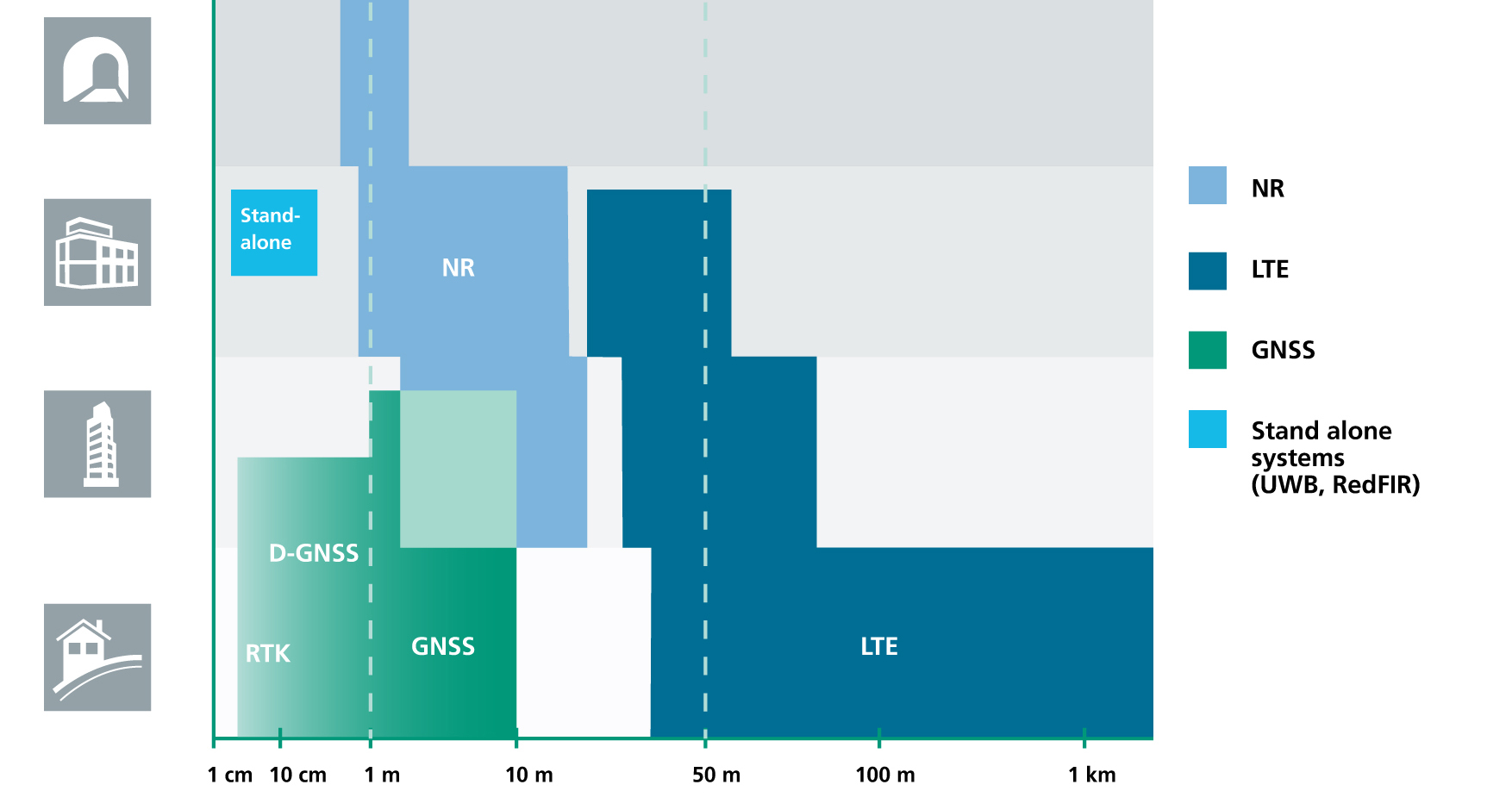
The 5G positioning framework will thereby integrate a multitude of sensors based on both, cellular signals and 3GPP independent techniques, into a hybrid positioning scheme, according to the Fraunhofer Institute for Integrated Circuits (IIS) in Germany. Fraunhofer IIS is currently prototyping low-latency and high-precision positioning systems for legacy LTE and future 5G New Radio (NR). Two selected industrial IoT live demonstrations can be seen at next week’s Mobile World Congress 2018.
Respective positioning performance for 5G NR and other technologies in different environments. (Image: Fraunhofer IIS)
5G NR enables positioning performance by providing high bandwidths for precise timing, new frequency bands at mm-wave, massive MIMO for accurate angle-of-arrival estimation and new architectural options that support positioning. Improved levels of accuracy, robustness and latency, not possible today, can soon be achieved, according to Institute. 5G provides fast and reliable access to moving objects, to achieve time-critical process control and optimization in industrial environments not possible with today’s cellular technology. As requirements vary according to the specific use cases, 5G NR will provide a flexible air interface allowing for scalable bandwidths, data rates, latencies, and positioning accuracy levels.
High-Precision Positioning
With location awareness becoming an essential feature of many new markets, positioning is an integral part of the system design of 5G mobile networks. Increased contextual awareness of goods, parts, machines and workers will enable new interaction and collaboration.
High-precision positioning, in the view of Fraunhofer IIS. (Image: Fraunhofer IIS)
Fraunhofer IIS is working on novel approaches for sub-meter accuracy to enable tracking of mobile devices in indoor and urban areas where GNSS is not sufficiently accurate nor available. Its 5G positioning framework integrate several sensors. The key benefits of 5G in this regard are high accuracy, reliability, mobility and coverage; low latency and low power; and scalability.
The Institute offers the facilities of its Test and Application Center L.I.N.K. in Nuremberg, Germany. The test center includes a 3D positioning system capable, according to the organization, of reproducing, simulating and emulating all kinds of possible environments, using every common communication and positioning system commercially available.