Centimeter-accurate, multi-constellation, multi-band, dual-antenna, RTK and affordable GNSS/INS solution
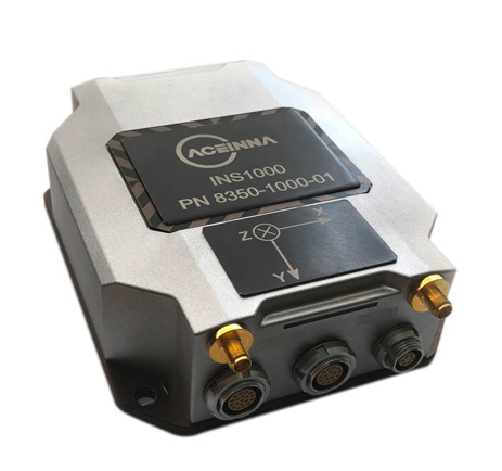
Aceinna is offering the INS1000 high-performance dual-band real-time kinematic inertial navigation system (RTK INS) with built-in inertial sensors for construction, agriculture and automotive applications.
Aceinna has also launched an OpenIMU package for autonomous vehicle guidance and navigation.
INS1o00
Photo: Aceinna
The INS1000 embeds Aceinna’s nine-degree-of-freedom inertial sensor technology to achieve automotive dead-reckoning performance in GNSS-challenged environments like urban canyons, heavily tree-lined roads, tunnels, underpasses and bridges.
The dual-frequency RTK and tight coupling between GNSS and inertial sensors provide centimeter-level accuracy, enhanced reliability, and superior performance during GNSS outages, the company said.
“Without access to satellite delivered guidance and localization information, autonomous vehicles can quickly get off track,” says Mike Horton, CTO of Aceinna. “The INS1000 delivers the essential detailed position and heading accuracy at a price point that is suitable for startups as well as fleet-wide vehicle deployment. As the leading supplier to the precision agriculture autosteer market, Aceinna is focused on driving the cost and complexity out of GNSS/INS solutions to enable widespread adoption in automotive ADAS applications.”
INS1000 is an integrated navigation system consisting of an inertial measurement unit (IMU) and other sensors. It provides the position, velocity and attitude information of the vehicle. A dual-frequency (L1/L2), dual-antenna GNSS receiver is used as the primary aiding sensor. Also supported is a distance measurement indicator (DMI) which can be attached to a wheel of the vehicle/robot to measure the rotation rate of the wheel. Integration of a DMI would give an improved solution in challenging environments: urban canyons, tunnels, warehouses and indoor facilities and campuses.
With horizontal position accuracy of 2cm (RTK), vertical position accuracy of 3cm (RTK), and velocity accuracies of 0.01m/s and 0.02m/s (horizontal and vertical, respectively), the INS1000 provides the precision navigation capabilities required for the automotive autonomous, automotive track testing, precision agriculture, and construction markets.
The INS1000 is compatible with all major global satellite systems (GPS, GLONASS, Beidou, Galileo, SBAS); it supports USB, Ethernet, CAN and RS-232 interfaces; and it supports dual GNSS antennas for accurate heading in static and dynamic scenarios, and difficult magnetic environments.
The easy-to-use embedded software allows extensive configuration and diagnostic capabilities. For optimal flexibility, the tools enable configuration of the output position, initialization of heading, IMU transformation matrix, GNSS antenna lever-arms, and NTRIP client. The control software can log and decode output data from the system or use the web application to plot results on a map.
Open IMU Package
Aceinna also offers an OpenIMU package. Its three key parts are:
a family of IMUs (three high-accuracy accelerometers, three high-accuracy gyros, and a powerful ARM Coretex);
an OpenSource tool chain and reference code for programming the IMU, with everything from basic download and debug to reference implementations of loosely coupled GPS/INS
a full developer site and tools with charting, graphing and algorithm simulation.
TDK’s booth at the Consumer Electronics Show (CES) is in South Hall 3, Booth #30306, and offers a look at sensors, passive components and more from TDK and its group companies. (Photo: TDK)
TDK Corporation has launched its InvenSense Coursa Drive software, an inertial-aided positioning solution for autonomous vehicle platform developers.
A high-performance extension of the InvenSense Positioning Library (IPL) that has provided sensor-aided positioning to more than 50 million devices worldwide, Coursa Drive enhances inertial-only vehicle positioning to <0.2 percent of distance traveled. These precise levels of accuracy are critical to maintaining decimeter lane-level vehicle positioning in challenging GNSS/perception system environments.
Coursa Drive’s inertial navigation system (INS) calibrates using absolute position inputs from either high-accuracy GNSS receivers or from perception-based systems (camera, radar, lidar) with high-definition (HD) maps.
In real time, Coursa Drive provides high-rate, 100 Hz delta positions and orientation to the autonomous vehicle (AV) system, complementing the lower-rate position references from GNSS and perception systems.
For improved system fault-tolerance, Coursa Drive can provide decimeter position precision for short periods when the GNSS or perception systems are uncertain or unavailable.
For non-real-time applications such as HD map creation and maintenance, Coursa Drive’s offline mode reprocesses INS data at two to three times higher accuracy than real-time mode, providing HD map companies alternative position references to verify HD map accuracy, even without GNSS, for up to 60 seconds.
“Coursa Drive delivers vehicle dead reckoning accuracy equivalent to high-end systems costing thousands of dollars,” said Mike Housholder, senior director of the TDK InvenSense Location Software and Services Business. “Our cost-effective software solution will help AV platform and Tier 1 vehicle manufacturers scale beyond prototype vehicles to high-volume mass production.”
Coursa Drive provides autonomous vehicle platform developers with maximum flexibility for system integration. The solution is platform agnostic and can operate on Cortex-M4F-class microcontrollers, or higher, and supports most dual-frequency GNSS receivers. The Coursa Drive API specifications are available upon request.
Coursa Drive is thoroughly tested and characterized using the InvenSense line of automotive-grade IMUs, including the IAM-20680 and IAM-20680HP, as well as several industrial grade IMUs. Coursa Drive is available now for select early partners and customers.
TDK and its group companies offering a comprehensive portfolio of sensors, electronic components and solutions for mobile, wearables, AR/VR, automotive, IoT and industrial applications will be at CES 2019, showcasing the Coursa Drive solution, along with additional innovative sensor solutions, in Booth #30306, Las Vegas Convention Center, South Hall 3, Jan. 8-11, Las Vegas.
Main applications
Level 2 to Level 5 advanced driver-assistance systems (ADAS)
Robotaxis
Trucking
Precision agriculture
Key features
World’s first high-precision inertial-aided positioning software for AVs
Inertial-only decimeter precise positions provided during short GNSS or perception system outages/uncertainties
High-rate, 100 Hz position and orientation updates supplied to the AV system
GNSS-agnostic software solution offers flexible integration for full-stack AV solution providers
Unique offline mode further enhances accuracy by two to three times for HD map building and maintenance applications.
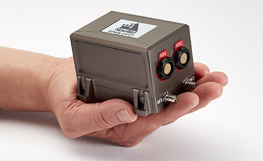
NovAtel is now delivering its SPAN tightly coupled GNSS+INS navigation technology in a rugged, ultra-compact unit.
Commercially exportable and designed for integration into a wide variety of applications, the high-performance SPAN CPT7 delivers assured positioning anywhere, in a package one-quarter the size of the company’s SPAN-CPT.
SPAN technology leverages generations of precise positioning expertise and advanced algorithms to tightly couple GNSS and inertial navigation system (INS) measurements. The system enables continuous, robust positioning and fast reacquisition in challenging navigation environments where GNSS signals may be unreliable or unavailable for short periods.
The new SPAN CPT7 also incorporates dual antennas to deliver instant alignment, along with interference detection and mitigation using NovAtel’s OEM7 Interference Toolkit (ITK) technology.
Integrators can take advantage of a spectrum analysis function of ITK to identify interference within the GNSS frequency bands and whether interference is coming from the external environment or due to other components in an integration project, NovAtel said. Mitigation features within ITK allow developers to implement digital filters and eliminate the problem.
Combining the multi-frequency, multi-constellation technology of the OEM7720 receiver board with ITK and the high-performing micro-electromechanical systems (MEMS) IMU, the SPAN CPT7 delivers anti-jamming functionality in an ultra-compact enclosure that fits in the palm of your hand. When paired with the GPS Anti-Jam Antenna (GAJT) in military applications, SPAN CPT7 is an integral part of assured position, navigation and timing (A-PNT).
“The remarkable new SPAN CPT7 delivers solutions for defense, mobile mapping, and autonomous vehicle applications with more flexibility than ever before,” said Neil Gerein, director, product management, NovAtel. “This new product saves customers space and weight without compromising accuracy or performance.”
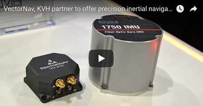
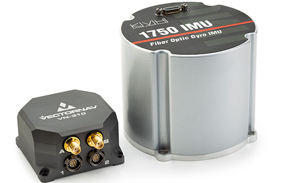
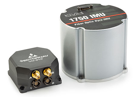
Inertial sensor companies KVH Industries and VectorNav Technologies partnered so that KVH’s fiber optic gyro-based 1750 and 1775 IMUs can now be offered to enhance the operation of VectorNav’s VN-210 and VN-310 Tactical Series GNSS-aided inertial navigation systems. In this video, VectorNav’s Jeremy Davis offers an overview of the partnership.
The products are on display in KVH’s (#2600) and VectorNav’s (#2214) booths at the AUVSI Xponential conference in Denver, Colorado, taking place April 30-May 3.
The VectorNav Tactical Series products with KVH’s FOG-based inertial measurement units (IMUs) combine the precision and reliability of KVH’s FOG technology with the robust filters and high-performance navigation algorithms of VectorNav’s inertial navigation systems.
The combined capabilities represent an affordable, effective alternative to larger, higher-cost inertial navigation systems and provide improved accuracy in challenging environments, the companies said.
Photo: VectorNav/KVH
VectorNav’s Tactical Series includes an onboard micro-electromechanical systems (MEMS)-based IMU, which provides some advantages for customers who have constraints in terms of size and weight in their navigation and stabilization applications.
However, in terms of inertial accuracy, the most demanding applications require performance that can only be delivered by FOG-based IMUs, for which KVH is a leading provider.
The VectorNav Tactical Series products with KVH FOG-based IMUs are designed for such applications as:
Satcom On The Move
gimbal and camera pointing and stabilization
weapons systems targeting and stabilization
autonomous vehicle navigation
lidar mapping
georeferencing
or any application where MEMS-based solutions are unable to deliver sufficient accuracy and precision.
Watch this video from Xponential 2018 to learn more about the partnership.
A single cable connects the two systems, running from KVH’s 1750 IMU or 1775 IMU directly to the auxiliary port on the VN-210 or VN-310. This pairing creates a fully integrated FOG-based inertial navigation system designed to provide a high-accuracy, continuous positioning, velocity, and attitude solution.
KVH is a leading innovator for assured navigation and autonomous accuracy using high-performance sensors and integrated inertial systems. KVH’s widely fielded TACNAV systems are in use by the U.S. Army and Marine Corps as well as many allied militaries around the world.
KVH’s FOGs and FOG-based IMUs are in use today in a wide variety of applications ranging from optical, antenna, and sensor stabilization systems to mobile mapping solutions and autonomous platforms and cars.
“We are pleased to feature KVH technology in our Tactical Series and give our customers the option of utilizing a FOG-based IMU for higher precision performance to support a wide range of demanding applications,” said Jakub Maslikowski, director of sales and marketing for VectorNav.
“The combination of VectorNav’s Tactical Series products with our FOG-based IMUs provides a great solution for applications that require advanced inertial navigation capability and FOG-level IMU performance,” said Jay Napoli, vice president of FOG/OEM sales for KVH.
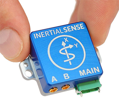
Inertial Sense has announced the availability of a micro-sized rugged version of its combined GNSS-INS module, which has an onboard GNSS receiver as well as a fully fused inertial navigation solution.
Designed to fill autonomous vehicle and sensing needs, the module is also available in AHRS/IMU versions.
At 10 grams and with 1 x 1-inch footprint, the solution provides accuracy of 0.1-degree roll/pitch and 0.3-degree dynamic heading. It is also ITAR-free module.
The modules represent 15 years of inertial navigation and motion measurement experience, according to the company.
“When I set out on this journey to provide an accurate and low-cost navigation solution, I wanted to produce a product that engineers could purchase off the shelf, hassle free,” said company founder Walt Johnson. “In my past as a UAV engineer, I was always looking for ways to save myself time and money. It’s all about convenience. There is no need to spend time choosing IMU sensors and writing the algorithms to fuse navigation data. We provide it all for you.”
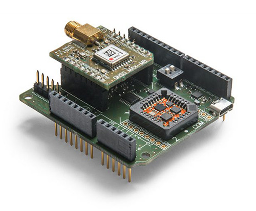
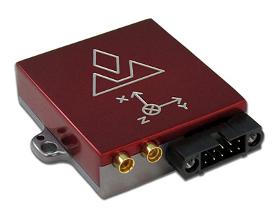
Xsens has expanded its MTi product portfolio with the introduction of the MTi-7, a miniature inertial navigation system (INS) module that uses input from an external GNSS receiver to provide an accurate, real-time position, velocity and orientation data stream.
The module has a compact 12 x 12-millimeter footprint, weighs less than 1 gram and consumes under 100 milliwatts, making it suitable for use in space- and power-constrained devices such as drones, as well as autonomous or remote-controlled mapping and imaging equipment.
Image: Xsens
Operating at output data rates up to 800 Hz, the MTi-7 achieves very low latency of 2 milliseconds, allowing for real-time operation of dynamic functions such as flight control and camera stabilization, the company said.
The module also offers a position and velocity output suitable for the navigation of autonomous ground vehicles in sectors such as smart farming and robotics.
The high performance of the MTi-7 is due to the advanced sensor fusion algorithms developed by Xsens to synchronize the inputs from the module’s onboard accelerometer, gyroscope and magnetometer with the signals from an external GNSS receiver or barometer.
The raw sensor signals are combined and processed at high speed in the MTi-7 module to produce a real-time data stream showing the device’s horizontal and vertical position, velocity, roll, pitch and yaw. This user-friendly data stream may be supplied to a host processor via a standard I2C, SPI or UART interface.
Based on the design of the successful MTi 1-series, the MTi-7 offers a straightforward upgrade path for current MTi-1 users on the same form factor. It is also able to provide heading, positioning and orientation accuracy more commonly found in much larger, heavier and higher power devices.
Image: Xsens
:We are seeing exploding demand for accurate control of autonomous or computer-guided equipment such as drones and smart farming ground vehicles,” said Hein Beute, director of product marketing at Xsens. “With its tiny footprint, light weight and low power consumption, the MTi-7 provides the industry’s best solution for any such application that is limited in terms of space or power but that needs a high degree of accuracy and precision in position and orientation data.’
The MTi-7 module is supported by an Arduino-compatible development kit (the MTi-7-DK), which provides access to the module’s I2C, SPI and UART interfaces via micro-USB connections.
Developers can configure the operation of the MTi-7 via the freely available Xsens MT Software Suite. The MT Software Suite includes a GUI for PCs operating on the Linux or Windows platforms, as well as a full Software Development Kit including example source codes and complete documentation.
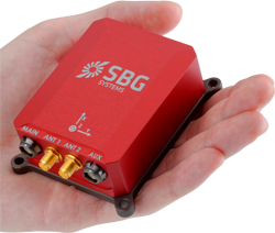
Viametris, specialist of SLAM-based mobile scanning systems, has launched a backpack-based scanning system called the bMS3D-360. The company continues to rely on SBG Systems’ expertise in inertial navigation by integrating the Ellipse2-D, an inertial navigation system with embedded real-time kinematic (RTK) GNSS receiver.
Photo: Viametris
Viametris has been developing SLAM-based scanning systems for more than 10 years, including the iMS3D, a full indoor mapping system and the VMS3D, a car-based mapping system.
The bMS3D-360 has been designed for the most challenging environments where GNSS is not accessible (indoor) or highly perturbed (urban canyons, forest, etc.). The surveyor starts the system, checks on a tablet that the GNSS and inertial information are computed, and starts the survey.
Back at the office, the user launches the INS/GNSS post-processing software to increase orientation and position accuracy, and then uses the Viametris software to georeference and colorize the point cloud.
Collected data are ready to be imported into common design software. This workflow (from collection to plan drawing) is seven times faster than a traditional method.
The bMS3D-360 offers a 360-degree camera, which greatly simplifies the treatment work. When navigating in the point cloud, the user opens a unique picture of the 360-degree scanned environment instead of looking at four different camera points of view.
Photo: SBG Systems
The Ellipse2-D from SBG Systems is a compact inertial navigation system integrating an L1/L2 GNSS receiver. This industrial-grade INS computes roll, pitch and heading as well as position because of its embedded Extended Kalman Filtering.
In real time, Ellipse2-D orientation data are used to correct the equipment attitude and help the SLAM computed heading. The embedded GNSS receiver provides absolute positioning to the point cloud as well as altitude constraint.
When the GNSS faces sources of disturbance, the INS maintains the trajectory were the SLAM technology is limited.
Red Bull Air Race has selected the VectorNav VN-300 dual-antenna GNSS-aided inertial navigation system (INS) as its primary source of aircraft telemetry data for Master Class raceplanes participating in the Red Bull Air Race World Championship.
Weighing less than 30 grams, the VectorNav VN-300 is a tiny dual-antenna GNSS-aided INS. It is used in applications ranging from autonomous vehicles to antenna pointing for satellite communication and aerial surveillance applications.
The inaugural event of the 2018 season in Abu Dhabi saw the VN-300, manufactured by VectorNav Technologies, used for the first time in all 14 aircraft to provide real-time telemetry data used for judging, in-race simulation and virtual reality applications.
Created in 2003, the world championship has held more than 80 races around the globe. The motorsport competition combines speed, precision and skill.
U.S. pilot Michael Goulian performs during the finals at the first round of the Red Bull Air Race World Championship in Abu Dhabi on Feb. 3.(Photo: Andreas Langreiter, Red Bull Content Pool)
Using the fastest, most agile, lightweight racing planes, pilots hit speeds of 370 km/h while enduring forces of up to 10 G as they navigate a low-level slalom track marked by 25-meter-high, air-filled pylons. Pilots incur time penalties for hitting pylons, incorrectly passing through air gates or only exceeding 10 G for more than 0.6 seconds, among others.
Being an individual sport, spectators need a reference to see the difference between the pilots’ lines and speed through the racetrack. Red Bull Air Race Live TV uses an augmented reality (AR) solution known as the Ghost Plane to display the trajectory of the pilots’ runs for real-time comparison in the head-to-head rounds and the Final 4 that decides the winner of the race by time.
The Ghost Plane is driven by the position, velocity and attitude data gathered during flight from the onboard INS.
Critical to the success of the Ghost Plane is the accuracy of the telemetry data, which, given the high dynamics experienced during flight, is extremely difficult to obtain.
For example, as a plane races through a chicane and into a vertical turn maneuver, GPS signals are lost and the INS needs to rely solely on the inertial sensors to accurately estimate the position and velocity until GPS is fixed again in level flight.
The VectorNav VN-300. (Photo: VectorNav)
“We evaluated several different inertial navigation systems and struggled to find one that was able to perform in our dynamics,” said Alvaro Navas, sport technical manager for the Red Bull Air Race. “VectorNav’s VN-300 was the only product able to deliver the attitude, position and velocity data accuracy we require, and it did this out of the box, no customization was required. The sensor is really amazing.”
“We are really excited to be working with Red Bull Air Race,” said Gordon Hain, VectorNav product manager. “Not only are we able to provide accurate data for the race judges and spectators, but we are also able to provide valuable information to pilots and tacticians. With the VectorNav data in hand, they are able to compare actual flight trajectories with their simulations to find areas for improvement. We are looking forward to continued work with Red Bull Air Race in the 2018 season and beyond.”
Northrop Grumman Corporation has been awarded a contract from the U.S. Air Force for technology maturation and risk reduction in support of next-generation navigation systems.
Under the $49 million contract from the Air Force Life Cycle Management Center, Northrop Grumman will provide the preliminary hardware and software architecture design for the Embedded GPS/Inertial Navigation System (INS)-Modernization, or EGI-M, technology. The modernized system is expected to be available for platform integration starting in 2019.
Northrop Grumman’s EGI-M will be based upon modular, open systems architecture to support the rapid insertion of new capabilities and adaptability based on unique platform requirements. Additionally, EGI-M will incorporate M-code-capable GPS receivers, which will help to ensure the secure transmission of accurate military signals.
“We are dedicated to ensuring mission success and the safety of warfighters by providing an EGI-M solution that offers robust, accurate and reliable positioning, navigation and timing [PNT] information, even in GPS-denied conditions,” said Dean Ebert, vice president, navigation and positioning systems business unit, Northrop Grumman Mission Systems.
EGI-M technology is designed for compatibility with current systems on legacy aircraft, allowing ease of integration and rapid adoption of new capabilities.
EGI-M will also comply with the Federal Aviation Administration’s NextGen air traffic control requirements that aircraft flying at higher altitudes be equipped with Automatic Dependence Surveillance-Broadcast (ADS‑B) Out by January 2020.
ADS-B Out transmits information about an aircraft’s altitude, speed and location to ground stations and to other equipped aircraft in the vicinity.
Polynesian Exploration Inc. has launched its high-accuracy navigation system for demanding applications such as autonomous driving and unmanned aerial vehicles (UAVs).
Polynesian Exploration is a navigation startup founded by a group of navigation-industry veterans in Silicon Valley in October 2016.
The navigation system is designed to fully utilize the advantages of both GNSS and inertial navigation systems (INS) to provide centimeter-level position and velocity accuracy with dual frequency real-time kinematic, together with accurate attitude information (roll, pitch and heading).
The system provides superior short-term stability against satellite signal outages and highly accurate heading whether the system is static or moving, Polynesian Exploration said.
The rugged and waterproof system will be ready for shipment starting July 1.
Polynesian Exploration described the demand for high-accuracy GNSS/INS solutions this way:
By the year 2020, four GNSS are expected to be fully operational, which are GPS, GLONASS, Galileo and BeiDou. The abundance of measurements from multiple constellations around the world will enable unprecedented improvements in the accuracy, continuity and integrity of GNSS navigation systems.
Although GNSS signals have grown to become ubiquitous, all radio-navigation systems are subject to radio frequency interference, short signal blockages and severe multipath errors in certain environments (such as urban canyons).
INS can potentially mitigate integrity and continuity risks caused by those issues to a certain degree. Additionally, INS is able to compute and output user’s position, velocity and attitude at high frequencies. Reporting information to users at a high-frequency is essential for many vehicle control applications, such as self-driving cars, UAV flight stability or autonomous landing.
We design our navigation systems with various performances depending on user demands, which include, but are not limited to, up to 400-Hz position, velocity, attitude outputs and meters to center-meter level position accuracy.
They can also be operational in all weather conditions and will be available globally.
Additionally, we are able to integrate special sensors for each unique application as requested by our customers. We are driven by customer satisfaction and strive to offer the best experience for our customers.
Exploring IMU specifications and correlating them to performance of a final product can be daunting, as differences between MEMS sensors are not always apparent. This article presents achievable performances in fusion technology across a range of IMUs among the best in their respective performance categories.
The number of available options in inertial navigation systems (INS) has grown substantially over the last several years. Major advances have been made not only in inertial measurement unit (IMU) technology, but also in the ability to exploit sensor information to its fullest extent. In both cases, the largest impact can be seen in the micro-electrical-mechanical systems (MEMS) sensors. MEMS sensors are typically much smaller, lower power and less expensive than traditional IMUs. The net result of these improvements is a proliferation of INS systems at much lower cost than were previously available and, therefore, greatly increased accessibility to technology that has historically seen limited deployment. Selecting the appropriate sensor and fusion solution for a particular application can be very challenging due to the large and confusing spectrum of solutions.
The IMUs will be examined in the context of new enhancements to sensor fusion algorithms such as the use of INS profiles. The concept of INS profiles applies environment specific constraints to improve performance in certain types of vehicles, or motion profiles. External sensors such as odometers and dual antenna operation can also aid the solution considerably, but will be unused in this analysis except for occasional comparisons. These external aiding sensors are extremely helpful in many cases and are available to use with a proprietary tightly coupled GNSS+INS solution called SPAN, but this paper seeks to evaluate what performance can be achieved without such aids.
Real-world test results will be examined using a selection of IMUs with the latest SPAN algorithms to illustrate what kind of performance can be achieved with different sensors in difficult conditions. Despite their major advances over the past few years, there are many challenges involved with utilizing MEMS technology to provide a robust navigation solution, particularly during limited GNSS availability or low dynamics. The measurement error characteristics of these devices have improved dramatically, but are still much larger and more difficult to estimate than traditional sensors. Advancements in SPAN sensor fusion algorithms have enabled these smaller sensors to achieve remarkable performance, especially in applications where environmental conditions allow for additional constraints to be applied.
This testing focuses on the land profile, meaning the constraints applied to a fixed-axle vehicle. The test scenarios were selected in such a way as to provide results for ideal, poor and completely denied GNSS coverage.
INS Profiles
GNSS and IMU sensors are only one part of the overall INS system performance. The sensor fusion algorithms used to exploit the available sensor data to its utmost capability are equally as important. In this regard, several improvements have been made to the SPAN INS algorithms to enhance performance under a variety of scenarios.
The largest addition to the SPAN product line is the introduction of INS profiles. That is, environment- and vehicle-specific modeling constraints can be utilized to enhance the filter performance. For example, the land profile, which will be examined in depth in this article, is intended for use with ground vehicles that cannot move laterally. The assumptions introduced for land vehicles, however, are not necessarily valid for different forms of movement, such as those experienced by a helicopter. Therefore, profiles have been implemented via command, and controlled as required by the user, allowing for maximum performance depending on the application at hand.
The land profile is analogous to what has historically been identified as dead reckoning. It is a method that uses a priori knowledge of typical land vehicle motion to help constrain the INS error growth. In other words, it makes assumptions on how land vehicles move to simplify inertial navigation from a six-degree-of-freedom system to something closer to a distance/bearing calculation. The land profile takes the concept of dead reckoning, models it as an update type into the inertial filter and adds a few additional enhancements.
Velocity Constraints / Dead Reckoning. Amongst other optimizations, the land profile enables velocity constraints based on the assumption of acceptable vehicle dynamics. This includes limiting the cross track and vertical velocities of the vehicle. Of all the enhancements, this is the one most colloquially referred to as dead reckoning.
In its simplest form, dead reckoning is the propagation of a position without any external input. In this forum, external input generally refers to GNSS satellites. Without external input, dead reckoning is inherently dependent on assumptions of velocity and heading to propagate the position. These solutions have evolved by integrating inertial and directional sensors to provide more local input and improve the solution propagation. This also is not a perfect method, however, as inertial sensors have their own errors that grow exponentially over time. The land profile velocity constraints explain the bulk of optimizations SPAN has made to enable dead-reckoning performance in extended GNSS outage conditions.
Explaining the velocity updates involves using the current INS attitude (); the vehicle attitude ( ) is estimated by applying the measured or estimated IMU body to vehicle direction cosine ( ). From this, the pitch and azimuth for the vehicle is estimated.Using the magnitude of the measured INS velocity in conjunction with the derived vehicle orientation, the vehicle velocity is computed, allowing the expected vertical velocity and cross-track to be constrained.
A velocity vector update is then applied to the inertial filter to constrain error growth. The effects of this method are expected to be most apparent in extended GNSS outage conditions when the INS solution must propagate with no external update information.
Phase Windup Attitude Updates. Some applications are inherently difficult for inertial sensors due to the fact that these systems are reliant on measuring accelerations and rotations in order to observe IMU errors. When traveling at a constant bearing and speed, separating IMU errors from measurements becomes challenging, so any application that does not provide meaningful dynamics is more demanding on inertial navigation algorithms. This type of condition commonly appears in applications such as machine control, agriculture and mining.
Gravity is a strong and fairly well known acceleration signal, so the real difficulty in this type of environment is managing the attitude, and especially azimuth, errors. Attitude parameters become difficult to observe when the system experiences insignificant rotation rates about its vertical axis.
External inputs can be used for providing input during low dynamic conditions when rotational observations are weaker. These are particularly helpful in constraining angular errors and include the same types used to assist in initial alignment: dual antenna GNSS heading, magnetometers, etc. However, as the goal of this testing is to demonstrate the achievable performance from a single antenna GNSS system, this type of external aid was specifically omitted.
Utilizing a patented technique for determining relative yaw from phase windup, the system is able to distinguish between true system rotation and unmodeled IMU errors during times of limited motion. This is a novel way to extract additional information out of existing sensors rather than adding more equipment and complexity.
The phase windup update is used to constrain azimuth error growth during low dynamic conditions that are typically not favorable to inertial navigation. However, it does require uninterrupted GNSS tracking and is therefore applicable only in GNSS benign environments. This approach is expected to show the greatest benefit in low dynamic conditions and be directly attributable to azimuth accuracy, but only in conditions where GNSS availability is relatively secure.
Equipment and Test Setup
We paired OEM-grade GNSS receiver cards with a selection of IMUs in different performance categories. Since the OEM GNSS platform is capable of tracking all GNSS constellations and frequencies, we configured each receiver to use triple frequency, quad-constellation RTK positioning. The receivers were coupled with a wideband antenna capable of tracking GPS L1/L2/L5, GLONASS L1/L2, BeiDou B1/B2 and Galileo E1/E5b signals.
Three IMUs were tested: an entry-level MEMS IMU (UUT1), a tactical-grade MEMS IMU (UUT2) and a high-performance fiber-optic gyro-based IMU (UUT3).
All GNSS receivers and IMUs were set up in a single test vehicle and collected simultaneously for all scenarios. IMUs were mounted together on a rigid frame, and all receivers ran the same firmware build that were connected to the same antenna.
The tests were conducted using a single GNSS antenna with no additional augmentation sources, such as distance measurement instrument (DMI) or wheel sensor. These are extremely helpful in aiding the solution, but as previously mentioned, this testing seeks to demonstrate the possible performance without the benefit of additional aiding sources. Dependence on aiding sources is a very important distinction when comparing such systems.
The GNSS positioning mode used was RTK via an NTRIP feed from a single base station with baselines between 5–30 kilometers. This was done to try to minimize GNSS positioning differences between the three systems. L-band correction signals were not tracked, and PPP positioning modes were not enabled.
A basic setup diagram of each system under test can be seen in Figure 1.
FIGURE 1. Equipment set-up (not to scale).
Test Scenarios
Four test scenarios will be examined using all the equipment and algorithms described above. They are: urban canyon, low dynamics, parking garage and extended GNSS outage.
The urban canyon test is designed to show the performance of the system in restricted GNSS conditions. The challenge to this scenario is to maintain a high-accuracy solution when GNSS positioning becomes intermittent or even unavailable.
The low dynamics test is intended to illustrate the benefits of the land profile, and specifically the phase windup azimuth updates in maintaining the azimuth accuracy.
The parking garage test will show the efficacy of the velocity constraint models over the different IMU classes as the extended outage provides no external information to the INS filter whatsoever. Again, no other aiding sources were used.
Urban Canyon Test. The urban canyon environment has been and remains one of the strongest arguments in favor of using GNSS/INS fusion in a navigation solution. Because urban canyons are common, densely populated and, of course, a demanding GNSS environment, they represent both an important and challenging location to provide a reliable navigation solution. Typically, they contain major signal obstructions, strong reflectors and complete blockages (depending on the city). For this reason, they provide an excellent use case for INS bridging to maintain stability of the solution.
During most urban canyon environments, it is typically rare to incur total GNSS outages of more than 30 seconds. Therefore, this scenario examines the stability of the solution in continuously degraded, but not generally absent, GNSS. In this case, the coupling technique of the inertial algorithms rather than quality of the IMU dominates achievable position accuracy.
The receiver platform is capable of tracking all GNSS constellations and frequencies. This provides a significant benefit to test scenarios, such as the urban canyon, where the amount of visible sky is significantly restricted. In this case, the more satellites that are observable, the more the tightly coupled architecture can exploit the partial GNSS information.
Though position accuracy between IMUs is less apparent in this condition, attitude results remain separated by IMU quality, which is a major consideration for some mapping applications such as those using lidar or other sensors where a distance/bearing calculation must be done for distant targets.
Test data for this scenario was collected in downtown Calgary, Canada. The trajectory (Figure 2) includes several overhead bridges for brief total outages and some very dense urban conditions.
FIGURE 2. Urban canyon test trajectory.
Table 1 shows the RMS error results of the three systems running both the default and land profiles. The first thing to notice is that the errors are differentiated by IMU category, though the differences are fairly small in the position domain thanks to the tightly coupled architecture. However, because GNSS information is partially available, the differences seen in activating the land profile are fairly modest, especially as the IMU performance rises.
TABLE 1. RTK RMS errors for urban canyon.
As the clearest benefits of the land profile are seen on the entry-level MEMS IMU (UUT1), these will be explored graphically in Figures 3 and 4. Figure 3 shows the position domain, and the RMS differences can be seen in a few cases where the default mode errors increased faster than the land profile. An example of this divergence is most obvious around the 1500-second mark of the test during periods GNSS is most heavily blocked.
FIGURE 3. UUT1 position error (std vs. land). Source: GNSS
FIGURE 4. UUT 1 attitude error (std vs. land). Source: GNSS
Low Dynamics Test. The low dynamics test is designed to emulate conditions experienced by machine control, agriculture and mining applications. In this situation, GNSS availability is generally not the limiting factor and can be used to control the low frequency position and velocity errors of the INS system. The difficulty is managing the attitude, especially azimuth, errors because attitude parameters are very hard to observe without significant rotations or accelerations (Figures 5 and 6).
FIGURE 5. Low dynamics test trajectory. Source: GNSS
FIGURE 6. Low dynamic UUT1 position errors. Source: GNSS
The low dynamics test was collected in an open-sky environment and consisted of traveling in a straight line on a rural road for roughly 2 km at an average speed of 10–15 km/h.
As this type of scenario provides little physical impetus, the azimuth and gyroscope biases are not observable. The reason for this is due to the use of the first-order differential equations to estimate the navigation system errors. Essentially, the differential equations define how the position, velocity and attitude errors change (grow) over time based on each other and the IMU errors. The observability of a particular update is tied to additional states through the off-diagonal elements of the derived transition matrix with the accelerations and rotations experienced by the system.
The overall RMS solution errors for RTK are provided in Table 2. As evident by the results presented, the position and velocity errors are clearly constrained by the continuous RTK-level GNSS position regardless of whether the land profile is enabled or not. The real differentiator in the land profile is the attitude performance due to the use of phase windup as a constraint. Moreover, the attitude improvements are certainly tied to IMU quality.
UUT1 exhibited a noticeable improvement in the attitude performance, while the higher performance IMUs did not. This is not entirely unexpected as the precision of the phase windup is lower than that of the higher grade IMUs.
Looking at the data graphically, Figure 7 shows the effect of land profile on positioning performance in this scenario. The two solutions are indistinguishable on the plot, and are all within standard RTK-level error bounds as was indicated in the RMS table.
Figure 7 shows the attitude accuracy with and without the land profile enabled. Again, the largest gains are seen on the entry-level UUT1, so this is the graphic shown below. This shows how the error peaks of the azimuth estimates are constrained. All the sharp corrections in each plot correspond to the vehicle turning around at the end of each 2-Km line and illustrates how much more powerful a rotation observation can be in azimuth accuracy overall.
FIGURE 7. UUT1 attitude error (std vs. land).
Parking Garage Test. This test was carried out at the Calgary International Airport and was selected to show the INS solution degradation during extended complete GNSS outages. The test consisted of an initialization period in open sky conditions to allow the SPAN filter time to properly converge, followed by a 500-second period within the parking garage. During the interval within the parking garage there were no GNSS measurements available.
Figure 8 provides a trajectory of the test environment. The time spent inside the parking structure is evident on the center bottom of the image.
FIGURE 8. Parking garage test trajectory.
Unlike urban canyon environments that contain partial GNSS information, this exhibits an extended period of complete GNSS outage. During this type of scenario, the IMU specifications become much more significant. IMU errors directly translate to the duration the solution can propagate before the accumulated low-frequency errors of the IMU grow to unacceptable levels. System performance during the outage degrades according to the system errors at the time of the outage and the system noise. The velocity errors increase linearly as a function of attitude and accelerometer bias errors. The attitude errors will increase linearly as a function of the unmodeled gyro bias error. The position error is a quadratic function of accelerometer bias and attitude errors.
Position results from each IMU are shown for UUT 1 in Figure 9. This plot shows the error with the land profile on and off. Without the land profile, the second-order position degradation in an unconstrained system is clearly visible.
FIGURE 9. UUT1 position error (std vs. land ).
By enabling the land profile, the filter constrains IMU errors by utilizing a velocity model for wheeled vehicles. With the constraints, the position errors are startlingly reduced for UUT1 and then progressively less impactful as the IMU quality increases in UUT2 and UUT3, respectively. This makes sense as the IMU error growth is progressively smaller in those IMUs, so the effect of mitigating them is also reduced.
Extended GNSS Outage Test. An extension of the parking garage test is to evaluate the performance in a much longer outage. Instead of 10 minutes, an outage of one hour was tested. Also, due to the extremely long GNSS outage bridging, the effects of adding a DMI sensor (odometer) will also be explored as they are able to be used as a major additional aiding source.
The most common measure of dead-reckoning performance is error over distance traveled (EDT). Due to the very long duration outages in this test, the errors will be reported in error over distance traveled to conform to the typical reporting method. This test was conducted in a mixture of highways and suburban streets with an average speed of 65 Km/h, incorporating a moderate amount of dynamics.
This effect can be seen over the duration of the entire outage as well in Figure 9. In this case, the points are the RMS error over several tests. and the light background shroud represents the one-sigma confidence as time progresses. The confidence increases over time as the overall distance traveled also increases.
FIGURE 10. Land profile EDT with and without DMI aid over 1-hour GNSS outage.
Results and Conclusions
In testing a range of IMUs in some challenging scenarios, this paper has sought to illustrate what kind of performance is achievable using each kind of system. An added complexity is looking at what effect certain inertial constraint algorithms have on this solution.
Although low-cost MEMs IMUs are continuing to greatly improve in quality and stability, the end application is still highly correlated to the overall performance of a selected INS system. For a great many applications, the MEMS devices in combination with a robust inertial filter can meet requirements and provide excellent value. However, some applications continue to require higher end sensors, and possibly post-processing to meet their needs.
The ability of SPAN to utilize partial GNSS measurements such as pseudorange, delta phase and vehicle constraints means even low-cost MEMs are capable of providing a robust solution in challenging GNSS conditions. However, this tightly coupled integration is limited in cases where GNSS is completely denied or when in low dynamic conditions.
INS profiles using velocity constraints, phase windup and robust alignment routines have been shown to provide substantial aid to the INS solution in tough conditions, such as GNSS denied or low dynamics. These improvements were shown to exhibit greater impact as the IMU sensor precision decreases. These abilities, in conjunction with the existing tightly coupled architecture of SPAN and the ever-increasing accuracy of MEMS, IMUs indicate that robust GNSS/INS solutions will continue to proliferate at lower cost targets. However, very precise applications such as mapping will continue to rely on higher quality sensors to meet strict accuracy requirements.
ACKNOWLEDGMENTS
The authors thank Trevor Condon and Patrick Casiano of NovAtel for collecting and helping to process the data presented in this article, and to Sheena Dixon for her tireless editing.
Manufacturers
NovAtel SPAN technology on the NovAtel OEM7 receiver is the testing and development platform for this research. NovAtel OEM7700 GNSS receiver cards and a NovAtel wideband Pinwheel antenna were employed. The inertial units under test were an Epson G320 (low-power, small-size MEMS IMU); Litef μIMU-IC (larger tactical-grade performance IMU still based on MEMS sensors); and a Litef ISA-100C (near navigation-grade IMU using fiber-optic gyros (FOG). Although all are excellent performers in their class and capable of providing a navigation-quality solution, the intent is to show the potential limitations that might arise due to the intended application.
RYAN DIXON is the chief engineer of the SPAN product line at NovAtel Inc., leading a highly skilled team in the development of GNSS augmentation technology. He holds a BSc. in geomatics engineering from the University of Calgary.
MICHAEL BOBYE is a principal geomatics engineer at NovAtel and has participated in a variety of research projects since joining in 1999. Bobye holds a BSC. in geomatics engineering from the University of Calgary.