Tersus GNSS Inc. is now offering the INS-T-306, a GNSS-aided inertial navigation system. The INS-T-306 is the advanced module that combines GPS L1/L2, GLONASS, BDS navigation and a high-performance strap-down system. It is capable of determining position, velocity and absolute orientation (heading, pitch and roll) for any device on which it is mounted.
The launch of the INS-T-306 aims at facilitating motionless and dynamic applications that need high accuracy, such as vessels, ships, helicopters, unmanned aerial vehicles (UAVs) and unmanned ground vehicles (UGVs).
The INS-T-306 utilizes an advanced GNSS receiver, barometer, magnetometers, micro-electro-mechanical (MEMS) accelerometers and gyroscopes to provide accurate position, velocity, heading, pitch and roll of the device under measure.
Besides GPS L1/L2, GLONASS and BDS, the unit supports differential GPS and real-time kinematic (RTK). It is able to integrate into lidar (Velodyne, Riegl and Faro brands). The on-board sensor fusion filter, navigation and guidance algorithms, and calibration software inside all make INS-T-306 a commercially exportable GNSS-aided inertial navigation system.
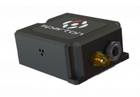
Inertial Sense will be releasing a high-quality, low-cost navigation system — the μINS — later this summer, the company said. The company made the announcement at AUVSI’s Xponential 2017.
Inertial Sense is a privately owned U.S. company that specializes in designing and manufacturing GPS inertial navigation technology for commercial and consumer products.
Historically, quality GPS inertial navigation has been expensive and was only designed into a small number of systems. As the commercial and consumer drone industries grow, the need for an accurate, low-cost navigation system has become more apparent, Inertial Sense said.
Acccording to Inertial Sense, the company’s engineers have invented a design that enables the technology to be smaller and less expensive.
The μINS is a tiny sensor module that is designed to provide high-quality direction, position and velocity data for drones and robotic applications. It provides this data by fusing sensor data from GPS (GNSS), gyros, accelerometers, magnetometers and a barometric pressure sensor.
iXBlue — a subsea navigation, positioning and imaging systems company — is offering two new positioning sensors.
Fifth-generation Octans
iXBlue is offering its customers the opportunity to upgrade their fourth-generation Octans positioning reference system to the fifth-generation system. The fourth-generation Octans was manufactured beginning in January 2014.
Built on iXBlue’s high-performance fiber-optic gyroscope technology, the Octans is an all-in-one gyro compass and motion sensor (attitude and heading reference system) with features such as IMO/IMO-HSC certification. The upgraded system provides extremely accurate real-time output for roll, pitch, heading and heave, as well as acceleration and rate of turns under challenging GNSS-denied environment.
Heading measurement accuracy has been doubled over the fourth-generation Octans: with still 0.1° Seclat in stand-alone, the system can now provide 0.05° Seclat with GNSS.
Moreover, the fifth-generation Octans now offers the ability to align on transit and the extended capability to deliver, in real time, accurate heave for swells up to 30 seconds.
The offer from iXBlue includes both the upgrade and calibration, backed by a five-year warranty.
Rovins Nano for remotely operated underwater vehicles (ROVs)
iXBlue has also launched a new inertial navigation system for the offshore industry, the Rovins Nano.
Based on iXBlue’s fiber-optic gyroscope technology, the Rovins Nano has been designed for ROV pilots performing maintenance and construction operations. It offers the stability and accuracy of the inertial position, outputting true north, roll, pitch and rotation rates.
“Rovins Nano is able to directly transmit the ROV’s position with extreme accuracy thanks to its integrated INS algorithm capable of collecting acoustic data,” said Paul Wysocki, iXBlue Rovins Nano product manager. “This is now possible regardless of the depth at which it is located: it is therefore not just an evolution, but rather a revolution for the middle water station keeping.”
Where the Doppler Velocity Log (DVL) has limitations, especially when operating in middle water, Rovins Nano is now there to guarantee optimal navigation safety.
“In the future, it will no longer be necessary to use a DVL,” Wysocki said. “Even in ‘sparse array’ LBL fields, with the presence of only one or two beacons, the combination between Rovins Nano and our Ramses acoustic system enables us to reach extremely accurate positioning data.”
A science ROV being retrieved by an oceanographic research vessel.
iXBlue provides more flexibility to its customers: by avoiding the use of DVL, operators reduce their operational and associated calibration costs.
Besides its high level of performance, Rovins Nano adapts itself to the user: the configuration, installation and product’s use have been considerably facilitated, while incorporating a system as complex as the inertial navigation system (INS). The ultimate goal is for the pilot to forget the existence of the product when maneuvering. Moreover, thanks to its compactness, lightness and open architecture with all third-party sensors, Rovins Nano is easy to integrate.
The French high technology company iXBlue is now offering an expanded range of subsea navigation systems, from ROV navigation to survey applications.
Northrop Grumman Corporation has been awarded an order to support embedded GPS/inertial navigation system (INS) pre-Phase 1 modernization efforts.
The Military GPS User Equipment (MGUE) program is developing M-code-capable GPS receivers, which are mandated by Congress after fiscal year 2017 and will help to ensure the secure transmission of accurate military signals.
Under the cost-plus-fixed-fee order valued at $4.8 million from the Joint Service Systems Management Office, Northrop Grumman will evaluate new GPS receivers’ modes of performance, including M-code and Selective Availability Anti-spoofing Module (SAASM).
Additionally, the company will perform trade studies, assess the state of development of MGUE for upcoming applications, and contribute to architecture development for next-generation GPS/inertial navigation systems.
“We are honored to help shape the next generation of navigation systems that will modernize the GPS infrastructure and keep our warfighters safer,” said Bob Mehltretter, vice president, navigation and positioning systems business unit, Northrop Grumman Mission Systems. “We are committed to using our navigation systems expertise to develop a solution that offers dependable and accurate positioning, navigation and timing information.”
The updated GPS/inertial navigation system will also comply with the Federal Aviation Administration’s NextGen air traffic control requirements that aircraft flying at higher altitudes be equipped with Automatic Dependence Surveillance-Broadcast (ADS-B) Out by January 2020.
ADS-B Out transmits information about an aircraft’s altitude, speed and location to ground stations and to other equipped aircraft in the vicinity.
The modernized system is expected to be available for platform integration starting in 2018.
The Inertial+ by OxTS improves measurements from a GPS receiver.
OxTS has successfully integrated a Locata receiver with its Inertial+ to create the first Locata+INS device, according to both companies. The device is capable of achieving centimeter-level accuracy where GPS systems fail.
The Inertial+ series, first developed in 2008, was designed for users who had an external GNSS receiver already, but still wanted to gain the benefits of an inertial system. The company has been able to combine OxTS’ Kalman filter and expertise in GNSS/IMU integration with its existing systems, meaning the user doesn’t have to pay for survey-grade integrated receivers.
Over the years, a number of popular GNSS receivers have been integrated with the Inertial+ to keep up to date with the market and make sure customers with the latest models can take advantage of the benefits the Inertial+ brings, OxTS said. Now, the Inertial+ has expanded from GNSS receivers and become the first inertial navigation system to integrate a Locata receiver, combining the many benefits of both systems, the companies said.
Locata is an innovative positioning system designed to complement rather than replace GPS, by addressing the issues and shortfalls of GNSS. As always, the Inertial+ allows Locata users to take advantage of their existing technology while enjoying the extra layer of measurements an aided-inertial navigation system brings.
Locata enables positioning in environments where GPS is either marginal or unavailable. Instead of using signals from satellites, a network of ground-based Locata transmitters (known as a LocataNet) can be set up around any specified local area. The LocataNet transmits GPS-like signals that allow any Locata receiver in the network to accurately calculate its position and time. Unlike GPS, where signals are too weak to penetrate into buildings, Locata’s signals are very powerful — more than one million times more powerful than GPS.
Additionally, with a locally based system (rather than a global satellite system), a user gains the benefit of having total control over both the reliability and quality of positioning solutions within the LocataNet coverage area. Locata systems are being sold today in many markets where GPS is unusable or unreliable, such as inside warehouses, on dockyards, in open-pit mines, for UAVs in urban areas, and for military uses where GPS is being actively denied by an adversary.
By combining the technologies of an inertial navigation system and a local positioning system, users have access to an extremely reliable and robust navigation solution, the companies said. Locata positioning data is fused with the IMU data in the Inertial+ with OxTS’ custom Kalman filter, creating a full 3D navigation solution with precise position, orientation, heading, velocity and acceleration measurements.
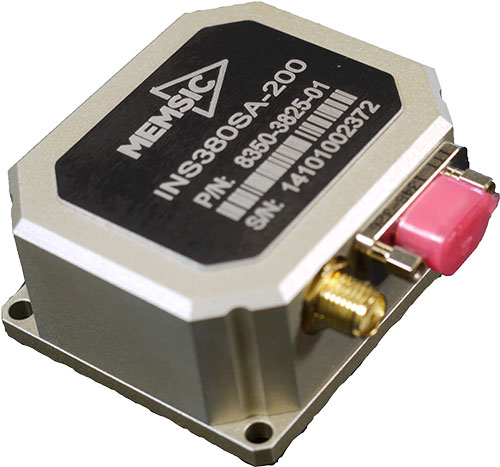
MEMSIC has launched its latest inertial system, the INS380 — a complete inertial navigation system with a built-in 48-channel GPS receiver. The INS380 is part of a portfolio of inertial systems enabled with MEMSIC’s SmartSensingtechnology for a broad range of precision-motion sensing applications.
The MEMSIC portfolio consists of inertial measurement units (IMU), vertical gyros (VG), attitude and heading reference systems (AHRS), inertial navigation systems (INS) and tilt measurement systems in a variety of packages for system designers and end-equipment manufacturers.
The SmartSensing technology enables a turnkey system with better than 0.01 m/s velocity measurement accuracy. The integrated 3-axis magnetometer allows for accurate operation when the GPS signal is lost or when the vehicle comes to a stop. SmartSensing provides users with sensor fusion and performance in critical motion sensing applications.
SmartSensing combines enhanced and patented Kalman-based algorithm with proprietary temperature, motion and alignment calibration for consistent and high-accuracy performance over a wide range of extreme operating conditions. Applications include unmanned ground and aerial vehicles, platform stabilization, avionics, precision agriculture, construction and more.
INS380SA-400 EVALKIT is available for evaluation and ships completer with an INS380 unit along with necessary accessories for quick installation. Designers can evaluate and configure the system using MEMSIC’s NavView Software, available for download.
Differential GNSS+INS for Land Vehicle Autonomous Navigation Qualification
By Gilles Boime, Emmanuel Sicsik-Paré and John Fischer
Land-vehicle autonomous navigation requires centimeter-level qualification tools to enable confidence build-up for delivery to open-road traffic insertion. External positioning sensors over a dedicated road section can be replaced with an embedded high-accuracy, highly responsive epoch-by-epoch differential GNSS receiver coupled with an inertial navigation system. The demonstrated absolute accuracy and mobility extends the potential test area and minimizes cost for multi-environment validation.
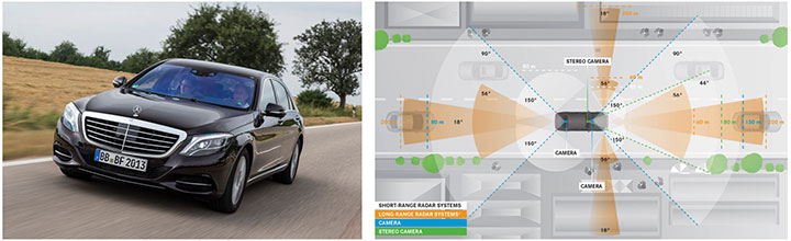
Cover courtesy of Mercedes.
Personal cars and commercial trucks are continuously improving the driver experience and safety thanks to integration of more significant and machine-assisted control systems. Advanced driver-assistance systems (ADAS) are now integrated in all luxury cars and moving into mainstream products. Technologies covered by ADAS are specific for each car integrator, but increasingly they include now involving more safety features, such as driver assistance and partial delegation to autonomous control for small maneuvers such as lane control. The generation of ADAS systems introduced in early 2015 on high-end models are engaging more intelligence from the control system such as:
Lane departure warning system
Speed assistance and control
Driver assistance and control
Autonomous emergency braking.
It is not only individual drivers who want this technology, but also governments that are getting involved to prevent accidents and minimize the economic impact associated with them. In the European Union, the general safety regulation 2009/661 was the first step to engage member-states to act as a regulator to mandate car safety improvements. The European Transport Safety Council, a non-profit private association, released in March 2015 a position paper titled “Revision of the General Safety Regulation 2009/661.” It promotes the introduction of lifesaving technologies like intelligent speed assistance, autonomous emergency technology including all speed and pedestrian detection, and lane-departure warning systems as the next step of regulation.
Car manufacturers are not far behind. They understand their customers’ expectation of minimized risk and enhanced driving experience. Telematics is also a path to convert a single vehicle into a fully intelligent, connected and entertainment object with an associated high value. So every car manufacturer is willing to be seen as a technology master.
Toyota, for example, plans to integrate collision-prevention technology in all its mainstream and luxury cars by 2017. The ADAS new generation focuses on radar-activated cruise control technology for the collision-prevention system. The control system maintains distance from a vehicle ahead and can stop the car if driver doesn’t react. The next step is to monitor driver attention with sensors like cameras focusing on the driver’s eyes, and the pressure of the hand on the steering wheel.
However, no fully driverless car is expected in the next 10 years. This technology is limited by legal issues and the lack of reliable nationwide mapping data.
Since the technology must be fully proven to prevent any lethal threat on the user and other drivers, most car and truck companies are working actively on qualifying driverless technology today. Nissan began testing driver-assist technology on open-road traffic in Japan in late 2013. It enables highly advanced systems such as lane-keeping, automatic lane change, automatic exit, automatic overtaking of slower or stopped vehicles, automatic deceleration during congestion on freeways, and automatic stopping at red lights. This is a step towards attaining fully automatic driving, targeted for 2020 by Nissan.
Some European manufacturers such as Daimler Benz are also early adopters. Daimler/Mercedes uses the Bertha Benz prototype car to test autonomous driving technologies. It merged multiple vision, radar and GPS sensor with digital map to monitor an open-road 100-kilometer trip in August 2013 (Figure 1).
Figure 1. Bertha Benz test car, left, running fully autonomous 103-kilometer trip in open road including 27 percent narrow urban roads. Right, networked sensor systems of the S 500 Intelligent Drive research vehicle.
All manufacturers are building driverless capability into their technology demonstration concept cars:
Mercedes with F 015 Luxury presented at the Consumer Electronic Show, early 2015;
Audi with Prologue, an extrapolation of test car RS7 concept equipped with SuperFast driverless pilot;
BMW’s electric i3 car is integrating ActiveAssist technology that enables portions of drive to be without any manual intervention, such as car parking and autonomous rally to a meeting point;
Google’s self-driving vehicle that conforms to California license requirements for driverless tests in open traffic;
Tesla model SD autonomous test car.
Although most market leaders agree that this is not a technology for mainstream production in the next few years, they all work very efficiently to master the technologies. It is a big challenge to integrate all the sensors and the navigation functions to autonomously and accurately position the vehicle on a map. The whole system must be certified to prevent any liability in case of a crash, a case that would engage the solution provider and the vehicle manufacturer.
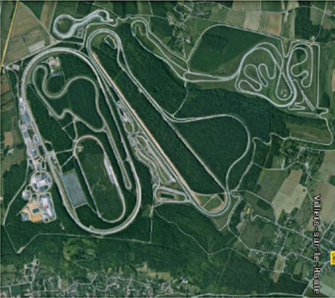
A large part of the qualification task will benefit from simulations and integration testing platforms in realistic conditions. At the very least, a very robust final open-space validation test must take place. Car manufacturers/integrators are using private test facilities in open air to perform serious trials before proceeding to real traffic conditions. Renault uses a 10-square-kilometer facility in France (Figure 2) to perform private tests in a protected area.
Figure 2. Renault outdoor test center at Aubevoye, France.
New autonomous car drive tests have mandated equipment enabling measurement of the car’s position on the track with an extremely high precision and repeatability. There are two competing technologies to do this:
Install many location sensors on the test track;
Use a general absolute positioning system.
Here we focus on an absolute positioning system that is affordable, easy to install and low maintenance. It is based on two main assertions:
The autonomous pilot can position accurately on the test track;
The test track is accurately referenced to the absolute positioning system.
We focus more closely in this article on the first assertion; the second one can be covered with a specific calibration trial where equipment, as discussed further, can be used in quasi-static mode and experience consistent accuracy. Let us have a deeper look at the candidate position technologies to verify autonomous pilot accuracy.
Positioning Technologies
Many technologies have been proposed to obtain vehicle position on the course. However, they all must be compatible with a reliable mapping database. Given the lack of consistent road infrastructure equipment with alternative capabilities, GNSS positioning is the sole enabling method to fit to a map every place around the world. That is why driverless systems always include a GNSS sensor to help other data matching with the map. The versatility and low cost of GNSS positioning makes it a candidate for open-air validation as well.
Standalone Standard Positioning Service GPS. The SPS single-frequency GPS receivers are included in so many nomadic appliances today that they are a commodity. Since their introduction 20 years ago, their performance is well understood. Some trials were performed in different area profiles with satellite constellation position dilution of precision (PDOP) < 2. Worse results were obtained from deep urban canyons in downtown Seattle, Wash.
For every technology, the relevant performance for the test course is the lateral error to the expected center of the lane in the two horizontal dimensions, referred to as 2D or N/E for orientation north and east.
For standalone SPS GPS, the lateral error standard deviation in 2D can be as high as 46 meters and have peak errors up to 660 meters. Lateral error in 3D can be as high as 20 meters with peak errors up to 175 meters.
Such performances are out of range for any positioning verification. It can only deliver a rough estimate of the point on the map, but would not provide tight correlation with other sensors for the navigation system.
Hybridized IMU and SPS GPS. Coupling of an absolute navigation GPS receiver with an inertial measurement unit (IMU) can mitigate corruption of the navigation solution when intermittent GPS signal outage is encountered. The hybrid approach is beneficial on any difficult signal transmission path from the satellite that is not line-of-sight: in urban canyons, deep foliage, under bridges, tunnels and in any multipath area. It also yields benefits in the very short term (less than a few seconds) for dispersion on the position computed from the sky.
Over the last 10 years, the combined benefits of micro-electro-mechanical sensors (MEMS) and tight coupling algorithms have raised the bar of positioning accuracy. It enables smoothed position along track and dead reckoning (DR) in case of GNSS signal outage.
Lateral error standard deviation in 2D is lowered to 2.3 meters and peak error up to 10 meters. However, this performance is still too poor to validate a vehicle position in the lane.
Hybrid Differential Single Frequency and IMU. The next step to mitigate systematic errors of the GNSS system is to use a set of multiple reference receivers in the vicinity of the area covering the test course. The reference receivers are static. The position of the reference is determined using long-term averages to mitigate constellation errors. A minimum for a position fix of 20 minutes is commonly reported. Then the position error standard deviation in 2D is less than 2 centimeters for baselines shorter than 100 kilometers.
For a MEMS integrated with a standard SPS GPS single-frequency receiver with DGPS correction on a mobile platform moving at less than 70 km/hour with HDOP < 1.4, Table 1 compares performance in a 2013 test.
Hybrid Differential Dual-Frequency Carrier Phase and IMU. The GNSS solution can be further improved, taking into account both L1 and L2 frequencies to mitigate propagation error and carrier phase to achieve ultimate signal accuracy. The combination of both helps solve ambiguities associated with the carrier-phase technique. When combined with a MEMS IMU, accuracy confirmed with HDOP < 1.6 is:
Lateral error standard deviation down to 0.18 meters;
Peak error of 0.6 meter.
However, this is still insufficient accuracy when compared to 0.1 meter required for verification testing.
With such low-cost IMU, GPS outages produce a rapidly increasing lateral error over elapsed time. The lower the speed, the poorer the position result.
Another limitation common to many differential solutions is the turn-on delay for the solution. It is also a repetitive issue in case of disruption of the GNSS solution. It extends the delay to recover from DR situation.
Geodetics’ Epoch-by-Epoch
Geodetics Inc. has developed a new class of instantaneous, real-time precise GPS positioning and navigation algorithms, referred to as Epoch-by-Epoch (EBE) and employing hybridized dual-frequency differential GPS with a high-performance IMU.
Compared to conventional real-time kinematic (RTK), integer-cycle phase ambiguities are independently estimated for each and every observation epoch. Therefore, complications due to cycle slips, receiver loss-of-lock, power and communications outages, and constellation changes are minimized. There is no need for the initialization period (several seconds to several minutes) required by conventional RTK methods.
More importantly, there is no need for re-initialization immediately following loss-of-lock problems such as those that occur when a mobile GPS receiver passes under a bridge or other obstruction, or when it loses satellite visibility during a shaded portion of road. In addition, EBE provides precise positioning estimates over longer reference-receiver-to-user-receiver baselines than conventional RTK.
This feature supports testing for long-range operations, for example, such as positioning a vehicle on a lane. The reference receiver is set in the vicinity of the test center track.
EBE requires the use of a minimum of two receivers, each of which is tracking a common set of five or more satellites and providing simultaneous dual-frequency phase data. Typically, one of the receivers is stationary, but this is not a requirement.
EBE has been proven utilizing dual-frequency receivers and operating at distances of up to 50 kilometers from the nearest base station in unaided mode. Additionally, the EBE algorithms operate in a network environment and make optimal use of all GPS measurement data at each epoch, gracefully degrading the position accuracies when some measurement data are not available. Furthermore, the system will make use of an IMU system, compensating for outages when line-of-sight to the satellites is blocked. This produces a robust and more reliable system.
Epoch-by-Epoch can deliver several benefits including:
Computationally efficient algorithms that provide a position estimate based on a single epoch in several milliseconds. This allows the real-time position estimate to be computed on the user platform (assuming reference station data is sent to the user platform).
An initialization period is not required. Since RTK requires some period of time (that can be measured in seconds to minutes) to perform ambiguity resolution, this is an important capability for platforms that:
require high accuracy (for example, for end-game scoring);
cannot see the satellites until launch;
have short flight or test course duration;
A re-initialization period following loss-of-lock is not required, unlike RTK, which needs to restart the integer-cycle phase ambiguity resolution process. This is another important capability because vehicle monitoring is considering EBE for dynamic applications where loss-of-lock and loss-of-data are likely.
However, it must be mentioned that many of the GPS receivers in use by the test (and training) community today do not support this dual-frequency requirement. Hence, those systems could not realize the maximum benefit.
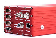
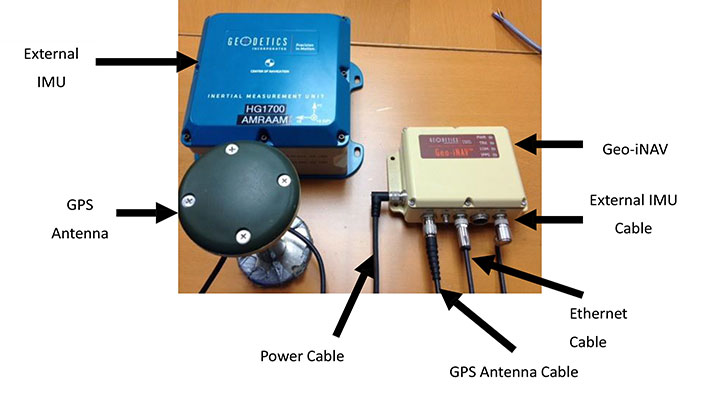
This technology is implemented in a rugged modular platform (Figure 3) with three main units:
A dual-frequency GPS antenna,
An integrated INS coupling GPS receiver with either an internal MEMS IMU or external IMU,
An external fiber-optic gyroscope (FOG) IMU for high-end accuracy and reliability. The external IMU is optional and dedicated to increasing the DR capability.
Figure 3. Dual-frequency differential navigation unit hybridized with external fiber-optic gyro.
Performance. Tests have been performed in conditions close to the land-vehicle navigation validation. It is based on measurements on-the-fly with no post-processing except for evaluation of the error.
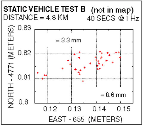
The first case is a static position of the rover 4.8 kilometers away from the reference receiver. Positions are updated once per second. The system includes a FOG IMU. the lateral error peak is less than 4 centimeters. Bias error is less than 1 centimeter. See Figure 4.
Figure 4. Single point error when rover is static.
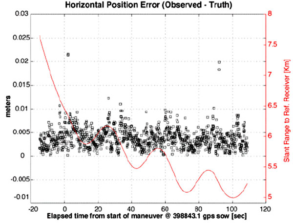
The second test case is with a high-dynamic mobile platform, moving at a speed of 200 km/h, with an average distance from the reference to the rover of 6 kilometers. Lateral error standard deviation is 0.5 centimeters, peak error is less than 2.2 centimeters. Bias error is lower than 0.2 centimeters (Figure 5).
Figure 5. Dynamic trial test single point error.
The performance in these test cases meets the expected accuracy for validation of autonomous navigation.
One last method to increase accuracy is to switch to a different class of IMU performance, from tactical grade to advanced. When in the line-of-sight of the GNSS sky-view, the performance is the nearly the same.
Conclusion
A real-time, differential Epoch-by-Epoch, dual-frequency carrier-phase GPS receiver, tightly hybridized with a high-performance IMU can provide absolute error lower than 5 centimeters in the 10-kilometer baseline range of the reference static receiver. This is fully adapted to the qualification of driverless auto-pilot systems for the targeted year of 2020. It can avoid the need to use complex theodolite and vision calibration systems. It provides maximum flexibility and minimum sustaining costs.
Acknowledgment
This study has been made possible thanks to materials provided by Geodetics Inc. and the advice of Jeffrey A. Fayman, vice president, Business & Product Development, Geodetics Inc. The results displayed in Figures 4 and 5 are from a test with a medium-sized UAV from Allied Drones, model EF44 high-endurance quad.
Manufacturers
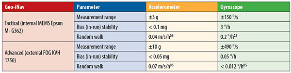
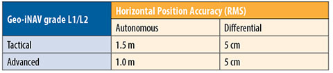
The Geo-iNAV family is a range of GPS-aided INS solutions available in different configurations, including various GPS receivers (L1, L1/L2 RTK, SAASM), internal MEMS or external FOG IMU. As part of this family, the Geo-RelNAV provides differential GPS relative navigation capability, the Geo-hNAV includes a dual GPS antenna receiver for static heading measurement capability, and the Geo-PNT combines position and attitude measurement with precise timing distribution.
Gilles Boime is is chief scientist for Spectracom. He is involved in GNSS signal generator, hybridized navigation platforms, GNSS timing and synchronization innovative solutions build-up. He holds an engineering diploma in telecommunication from Institut Superieur d’Electronique de Paris.
Emmanuel Sicsik-Pare is strategic product manager for Spectracom. He is involved in timing and navigation products and systems definition and application market monitoring. He holds a M.Sc degree from Telecom Bretagne.
John Fischer is CTO of Spectracom. He has more than 30 years experience creating navigation and communications systems, received his master’s in electrical engineering from SUNY at Buffalo. Prior to joining Spectracom, he worked in radar, command and control, and wireless systems.
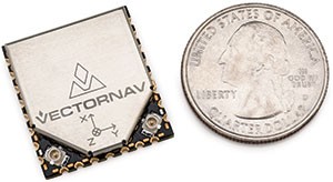
VectorNav Technologies has released a surface mount version of its VN-300 dual-antenna GPS-aided inertial navigation system (GPS/INS). It will be on display at booth 942 at AUVSI’s Unmanned Systems show, held May 5-7 in Atlanta.
Surface Mount Device
The VN-300 surface mount device (SMD) is a miniature MEMS-based inertial navigation module that includes both inertial navigation and GPS-compassing capabilities, which together provide high-accuracy position and velocity in both stationary and moving conditions. With the release of the surface mount version, VectorNav is also announcing the addition of GNSS capability to the full VN-300 product line. The VN-300 SMD completes VectorNav’s line of industrial grade inertial sensors, joining the VN-100 IMU/AHRS and VN-200 GPS/INS surface mount and Rugged modules.
Incorporating the latest MEMS sensor technology, the VN-300 combines 3-axis accelerometers, 3-axis gyros, 3-axis magnetometers, a barometric pressure sensor, two GPS receivers, and a low-power microprocessor into a rugged aluminum enclosure about the size of a matchbox. When in motion, the VN-300 couples the position and velocity measurements from the onboard GPS receivers with measurements from the onboard inertial sensors to provide position, velocity, and attitude estimates of higher accuracies and with better dynamic performance than a standalone GPS receiver or Attitude Heading Reference System (AHRS).
With the release of the surface mount version of the VN-300 the company says its own Rugged is surpassed as the smallest and lightest dual-antenna GPS/INS on the market. The surface mount VN-300 shares the same footprint and form factor with VectorNav’s surface mount VN-100 IMU/AHRS and VN-200 GPS/INS.
“The VN-300 surface mount chip is an achievement that combines the best of our expertise in inertial navigation algorithms and our innovative approach to miniaturizing embedded navigation sensors. There simply is no other product like it on the market,” said ohn Brashear, VectorNav’s president. “The VN-300 SMD completes our Industrial Series of inertial navigation sensors and paves the way for the expansion of our product lines into new markets and applications.”
The VN-300 is ideal for industrial and military applications that are size, weight, power and cost (SWAP-C) constrained, or that require an inertial navigation solution under both static and dynamic operating conditions, especially in environments with unreliable magnetic heading such as fixed-wing and multirotor UAVs, aerostats and other tethered UAVs, gimbaled camera systems onboard helicopters and multirotors, antenna systems onboard ground vehicles and marine vessels, weapons training and warfare simulation, and direct surveying.
New GNSS Capability
With the release of the surface mount version, VectorNav is also announcing the addition of GNSS capability to the full VN-300 product line.
The addition of GNSS capability now enables the VN-300 product line to include measurements from satellites in the GLONASS constellation in addition to GPS. These additional measurements provide greater tracking reliability and improved VN-300 performance in urban canyons and reduced visibility conditions.
Firmware Update
VectorNav is also announcing the release of a new firmware update for the VN-300 that improves the overall accuracy and time to acquisition of the GPS-compass feature. The new firmware also includes logic that enables the VN-300 to intelligently and seamlessly transition between magnetic heading (AHRS) mode, to INS operation in dynamic conditions and GPS-compass in static conditions, without requiring input from the user.
GAINS-10 provides accurate inertial navigation in the presence of mechanical shock, transient platform vibrations and extreme magnetic interference. It features high speed, synchronous sampling of all inertial systems combined with high rate coning and sculling compensation and is fully calibrated across temperature.
“The GAINS-10 delivers precise performance in complex environments,” said Jim Lackemacher, Group vice president of Sparton’s Defense & Security Engineered Products. “Sparton’s GAINS-10 provides flexible integration options and platform customization.”
High-speed synchronous sampling of all inertial sensors
Customizable on-board high speed digital filtering
Sculling and coning compensation
High-speed data logging capability to off-board uSD card
Ruggedized, shockproof design, with proprietary seals that allow barometric pressure sensing combined with IP67 performance
Low power consumption with power management functionality (Sleep Mode)
Interface to external GPS receiver
External data interface via Multi-GPIO connectivity
Powerful user programmable customizations via NorthTek(TM) Forth interpreter
Sparton AUVSI 2014 Events Schedule: Sparton Navigation and Exploration will be featured at the “Beyond the Booth” showcase Wednesday, May 14th at 11:30am (EDT).
Throughout the AUVSI show, Sparton will host in-booth presentations along with live demonstrations.
A Prototype System for Navigation in GPS-Challenged Environments
By Chris Rizos, Dorota A. Grejner-Brzezinska, Charles K. Toth, Andrew G. Dempster, Yong Li, Nonie Politi, Joel Barnes, Hongxing Sun, and Leilei Li
A team of Australian and U.S. researchers have integrated a ground-based system with GPS and INS to create a hybrid system that provides precise and accurate position information continuously in a variety of environments where GPS alone comes up short.
INNOVATION INSIGHTS by Richard Langley
GPS HAS ITS LIMITATIONS. Although it is a 24/7 global system, it doesn’t work everywhere. The microwave radio signals transmitted by the satellites are rather weak, and although they can provide excellent positioning performance when a receiver’s antenna has a direct line-of-sight view of a sufficient number of satellites well spread out in the sky, positioning accuracy degrades or becomes impossible when the signals are effectively blocked by obstacles such as trees, rock faces, and buildings outdoors and by roofs, ceilings, and walls indoors.
In many obstructed environments, the signals aren’t completely blocked but rather their power is severely attenuated so that they are no longer strong enough to be acquired and tracked by a conventional GPS receiver. Remarkable progress has been made in the development of super-sensitive receivers that, in conjunction with an appropriate antenna and assistance information provided over a mobile phone network, can provide position fixes in such environments. However, the precisions and accuracies of these pseudorange-based positions are often very poor — perhaps as low as 100 meters or more.
So, is it possible to obtain precise and accurate positions in obstructed environments? Well, we could add measurements from GLONASS (or other satellites) to GPS measurements, but GLONASS suffers the same problem as GPS, and while the additional satellites could be an advantage in some partially obscured areas there are many places where we won’t be any better off. We could use an inertial navigation system (INS), but such devices have their own weaknesses such as the requirement of initial calibration and the accumulation of position error with time. Are there any other technologies available?
We know GPS works very well when there is a direct line-of-sight view between the satellite transmitters and the receivers and carrier-phase measurements can provide decimeter- and even centimeter-accuracies. So why not develop a ground-based system that works in a similar way to GPS, which would allow you to place the transmitters wherever you like? Well, such a system has indeed been developed and in this month’s column, a team of Australian and U.S. researchers describes how they integrated the ground-based system together with GPS and INS to create a hybrid system that provides precise and accurate position information continuously in a variety of environments where GPS alone comes up short.
“Innovation” features discussions about advances in GPS technology, its applications, and the fundamentals of GPS positioning. The column is coordinated by Richard Langley, Department of Geodesy and Geomatics Engineering, University of New Brunswick.
The determination of the position and orientation (or “pointing direction”) of a device (or platform to which it is attached), to high accuracy, in all outdoor environments, using reliable and cost-effective technologies is something of a “holy grail” quest for navigation researchers and engineers.
However, ongoing research has identified two classes of applications that place stringent demands on the positioning/orientation device: (a) man-portable mapping and imaging systems that operate in a range of difficult urban and rural environments, often used for the detection of underground utility assets (such as pipelines, cables, conduits), unexploded ordnances and buried objects, and (b) the guidance/control of construction or mining equipment in environments where good “sky view” is not guaranteed.
The solution to this positioning/orientation problem is increasingly seen as being based on an integration of several technologies: satellite (GNSS including GPS) and terrestrial ranging systems, inertial navigation systems (INSs), laser guidance/scanning systems, and even electro-optical devices such as surveyors’ total stations or laser scanners. Each has its shortcomings, but within an integrated system, advantage can be taken of the complementary characteristics of several of these sensor technologies.
Centimeter-level accuracy positioning systems for outdoor use typically have at their core the GPS technology. GPS is, in fact, the most effective general-purpose navigation tool ever developed because of its ability to address a wide variety of applications: air, sea, land, and space navigation; precise timing; geodesy; surveying and mapping; machine guidance/control; military and emergency services operations; hiking and other leisure activities; personal location; and location-based services. The varied applications use different and appropriate receiver instrumentation, operational procedures, and data processing techniques. But all require signal availability from a minimum of four GPS satellites for three-dimensional fixes.
However, one of the usual limiting factors in using GPS is the need for direct line-of-sight between the satellites and the ground receiver. In particular, the robustness of positioning is compromised when GPS receivers are near or under trees, in urban/suburban areas, or in deep open-pit mines and construction sites, where there is partial sky view obstruction by buildings or walls. The traditional means of overcoming the gaps in navigation coverage due to satellite signal blockages is to use an INS. An INS (with its inertial measurement unit or IMU) is also the most convenient means of determining the orientation of the device or platform. The integration of GPS and INS can, in principle, overcome the defects of standalone INS (sensor errors that grow unbounded with time) and GPS (signal availability requirement). But navigation accuracy degrades rapidly if there are no GPS measurements to calibrate the INS sensor errors.
A new terrestrial RF-based distance measurement technology offers promise of continuous signal coverage, even in difficult urban/rural environments. This technology is known as “Locata.”
The Locata approach is to deploy a network of ground-based transceivers that cover an area with strong time-synchronized ranging signals. When a Locata receiver uses four or more ranging signals it can compute a high-accuracy position entirely independent of GPS or INS. However, a standalone Locata receiver has its own shortcomings: (a) in some situations it may be difficult to achieve good vertical dilution of precision due to logistical constraints of placing transmitters (to give a variation in elevation angle between the terrestrial transmitters and the receiver whose positions are to be determined), and (b) as with GPS, multiple receivers/antennas are required to derive orientation information.
What is therefore required is several carefully selected navigation sensor technologies, integrated within a single hardware package, the measurements from which are simultaneously processed to provide continuous, reliable, and accurate navigation solutions (that is, both position and orientation information).
In cooperation with Locata Corporation, the SNAP Laboratory within the School of Surveying and Spatial Information Systems at the University of New South Wales (UNSW) and the SPIN Laboratory at The Ohio State University have assembled a working prototype of a hybrid system based on GPS, inertial navigation, and Locata receiver technology to provide seamless and reliable navigation aimed at supporting vehicle guidance and control, open-pit mining, mobile and GIS mapping, and industrial applications.
Locata Technology
The SNAP Lab has been conducting pseudolite research for many years, and has experimented with pseudolites in nonsynchronous and synchronized modes for a variety of applications, using both the GPS L1 frequency as well as the 2.4 GHz ISM band frequencies. Locata Corporation has developed state-of-the-art RF terrestrial positioning technology (“Locata”), which consists of a network (“LocataNet”) of time-synchronized pseudolite-like transceivers (“LocataLites”). UNSW has assisted in the development of the technology through experimental testing and benchmarking. In a relatively open outdoor environment, the LocataNet can provide real-time stand-alone kinematic positioning (without a base station) at centimeter-level accuracy. Even in an indoor environment where LocataLite signals arrive at a Locata receiver via non-line-of-sight paths (penetrating the walls of buildings), the static positioning quality can be at the sub-centimeter level, and also at the sub-meter level for kinematic positioning.
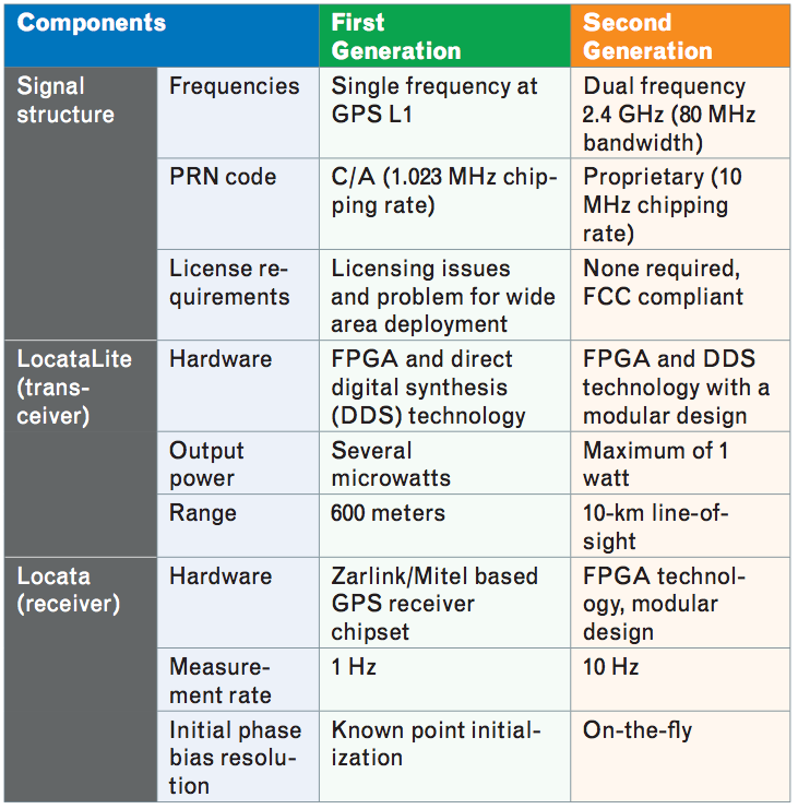
Locata has several advanced features that have been developed over a period of about 10 years through several technology generations, including a time-synchronized positioning network, network propagation to many LocataLites, improved signal penetration, change of transmitting frequency and signal structure, and spatial and frequency diversity.
In TABLE 1, the key characteristics of the two generations of Locata technology are listed. Using 2.4 GHz not only means the frequency is license-free, but also permits transceiver output power of up to 1 watt, which means greater operating distances (up to 10 kilometers). Using dual-frequency signals changes the initial phase-bias resolution from known-point initialization to on-the-fly (OTF), where the initial phase bias is resolved while the receiver is moving. The higher chipping rate (10 MHz) results in less pseudorange multipath error, because the delay in a reflected signal will rarely be more than two chips. The 10-Hz measurement rate allows relatively high velocities of the receiver.
Table 1. Specification summary of Locata’s first- and second- generation systems.
In terrestrial-based RF-based positioning, multipath error is more severe than with GPS, because the terrestrially transmitted signal arrives at the receiver at a very low (typically less than 10 degrees) or even a negative elevation angle, which can result in severe multipath signal fading. In the second-generation Locata system, spatial and frequency diversity techniques are employed. Spatial and frequency diversity are two of the three types of diversity principles (the other being polarization) that are common practices in terrestrial RF communications to mitigate against signal fading. The LocataLite transceiver uses two spatially separated (usually in the vertical) antennas, which transmit two signals at different frequencies. This gives a cluster of four diverse signals transmitted from one LocataLite. With this diversity technology, Locata kinematic positioning in moderately obstructed environments can provide centimeter-level quality with 100-percent coverage, as well as consistent geometry and high reliability. The Locata’s multipath mitigation technology is very important and relevant to this project, because the operational environments are often vegetated or wooded.
Triple Integration
As discussed in the preceding sections, there are both advantages and disadvantages to every navigation sensor. GPS and Locata have high positioning accuracy in open or moderately obstructed environments, but they are sensitive to signal blockage such as the case in dense forests, urban canyons, deep mine pits, and indoors. In contrast, INS is totally autonomous — that is, independent of external signal sources — and has high output rate for position, velocity, and attitude, but its unaided navigation error grows rapidly with time.
The most common data-processing tool to integrate GPS and INS is the Kalman filter, which forms the basis for multi-sensor integration in this research. The basic Kalman filter applies to linear system models. Therefore, several variations were developed to cope with the non-linear navigation model, such as the extended Kalman filter and the unscented Kalman filter.
The following discussion of the integration of the GPS/INS/Locata sensors is focused on two aspects: 1) the system state selection, and 2) the measurement model or integration model that decides which information to pass to the filter.
The error state vector consists of a nine-dimensional navigation error state sub-vector (three for the position, three for the velocity, and three for the orientation), an accelerometer error state sub-vector, a gyroscope error state sub-vector, and a three-dimensional gravity disturbance state sub-vector. Of course, other sensor error models can be considered for the gyroscope and accelerometer sensors, such as a combination of random constants, first-order Gauss-Markov variables, scale factors, and so on. In this case, the state space could have a dimension of more than 30. The objective is to adjust the sensor error model later based on experimental results (if needed). However, because of the limitations of observability, it is not yet known whether an augmented error state vector would give better results.
When integrating INS hardware with other sensors, the sensors cannot share the same physical location, which would be ideal from a theoretical point of view. Knowing the spatial relationship among the sensors is important to ensure the highest possible navigation performance. The displacement vectors or mounting biases are offsets, also referred to as lever arms, from the center of the IMU to the centers of the other sensors. These lever-arm parameters may be included in the Kalman filter and thus can be estimated. However, if the lever arms are precisely measured during the assembly of the system, they do not need to be included in the filter as estimable parameters.
For multiple sensor integration in a Kalman filter, there are essentially two types of general models: loosely coupled and tightly coupled. The loosely-coupled model uses a decentralized filter that has several sub-filters to process the sub-systems independently. In other words, the Kalman filter solutions from the sub-systems are combined in an overall Kalman filter that provides the integrated navigation solution. In contrast, the tightly-coupled model uses a single main filter to process the output of all sensors. In GPS/INS integration, tightly-coupled systems have obvious advantages in environments where GPS signals are frequently lost, because they can rely on the other sensor(s) when GPS positioning becomes impossible.
In the tightly-coupled model, the raw observations of all sensors will be input to the main filter. For GPS and Locata, the primary observations will be the carrier phase measurements, as code (pseudorange) observations cannot provide the required accuracy. High-accuracy GPS positioning needs to address the issue of carrier-phase ambiguity. The ambiguity can be treated as an unknown in the Kalman filter, but it may take several minutes to resolve the ambiguity using GPS alone. Using certain ambiguity resolution techniques, however, the ambiguity can be resolved outside the main filter in the GPS/INS high-precision (carrier-phase) integration filter. Note that if the ambiguity were to be resolved within the filter, this would increase the number of states of the filter. For the GPS component, ionospheric delay should be included for applications that cover a large area. Ionospheric delay can be resolved using network-based differential techniques,
but it will affect the ambiguity resolution for single baseline differential positioning if it is not included in the local solution. The filter is designed either to use, or not to use, ionospheric delay, which can ensure flexibility to accommodate network-based and single-baseline differential positioning.
As mentioned above, the measurement model in the tightly-coupled model is based on the raw observations. For GPS and Locata, the observations will be the carrier-phase observations. The approximate values for the linearization of the GPS and Locata measurement equations are provided by the INS navigation solution.
The GPS carrier-phase ambiguity is solved independently outside the Kalman filter with OTF techniques. The GPS differential positioning coefficient matrix remains the same regardless of whether or not a network-based differential technique is used. For velocity determination, the double-differenced Doppler observation is used to eliminate the clock error rate as an unknown (because it is difficult to model this in the filter). The initial carrier-phase bias of the Locata is also not included in the filter, because it can be resolved instantaneously with dual-frequency data in the Locata second-generation system.
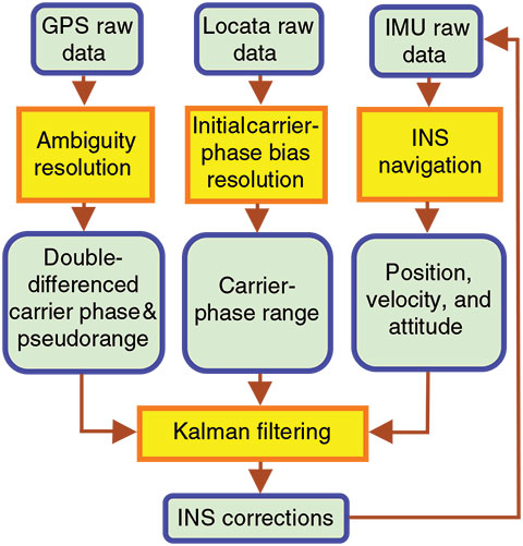
The implementation of the filter will be flexible, so adjustments can be made to account for actual environmental conditions. The filter is designed with an open interface and is modular in structure, so that components can be added (or removed) from the model. In open-sky areas, GPS is sufficient for system positioning, so only its observations need to be processed. In moderately obstructed environments, GPS and Locata observations will be processed. In this case the number of GPS observation equations is limited and sometimes will be less than four. FIGURE 1 illustrates the flowchart of the triple-integration of GPS, INS, and Locata.
Figure 1. Workflow of the integrated GPS/ INS/Locata system.
Field Tests
For experimental purposes, we used a dual INS, based on a navigation grade unit and a tactical grade unit. In addition, a Locata receiver and a dual-frequency GPS receiver were placed on a vehicle at Locata’s Numeralla Test Facility (NTF) near Canberra, Australia. This test site features both open-sky and obscured environments, allowing for testing the system’s performance under truly challenging scenarios. The test was repeated by mounting the devices on an autonomous electrical car, driven on the UNSW campus. In both cases, the separation between the rover and the terrestrial transmitters was between a few tens of meters to several kilometers. The GPS and Locata data were processed separately (for testing the internal consistency) as well in a hybrid solution, resulting in few-centimeter-level accuracy per coordinate, depending primarily on GPS availability and the geometry between the rover and Locata devices, as well as the level of multipath fading.
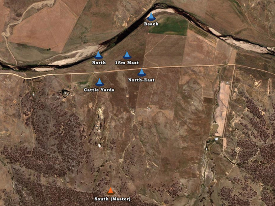
Test 1: NTF. The first integration test was conducted at the NTF on March 17, 2008. The NTF covers an area of approximately three hundred acres (2.5 kilometers × 0.6 kilometers) and is ideally suited to real-world system testing over a wide area. At the NTF, a number of LocataNet configurations are possible through the installation of permanent antenna towers. The network configuration used for this experiment is illustrated in FIGURE 2.
Figure 2. NTF: LocataLite network.
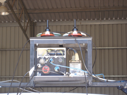
Before the test, a special mounting platform was designed and built. The platform, shown in FIGURE 3, consists of a two-level metal frame. The bottom level can accommodate two inertial measurement units, while the top level can hold up to four antennas. The platform can be easily attached to either the roof of the NTF test vehicle or to the body of UNSW’s small electric car (described later).
Figure 3. Devices setup for the NTF test.
The devices used in the test include two dual-frequency GPS receivers (one used as the rover receiver and the other as the base station), one navigation grade INS, and one Locata rover unit. The GPS antenna and the Locata antenna were mounted with the INS together on the top of a truck. The GPS data rates were set to 1 Hz. The average length of the GPS differential baselines was about 1.2 kilometers. The GPS observation conditions were good during the testing period. The Locata data rate was set to 10 Hz, while INS data rate was 256 Hz, and both were synchronized with the GPS time using SNAP-Lab-developed time synchronization devices based on field-programmable gate array (FPGA) technology.
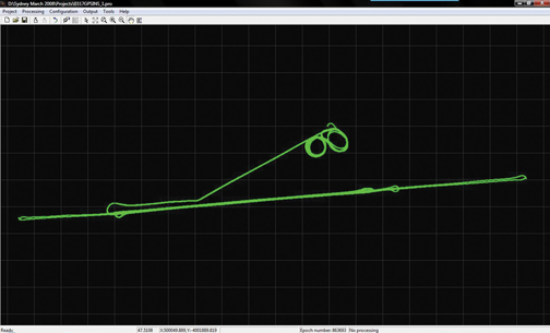
The GPS/INS data were first processed in tightly-coupled mode. The trajectory is depicted in FIGURE 4. The standard deviation of position, velocity, and attitude are shown in FIGURES 5-7 respectively.
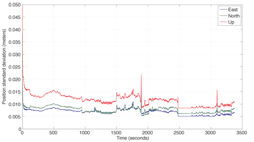
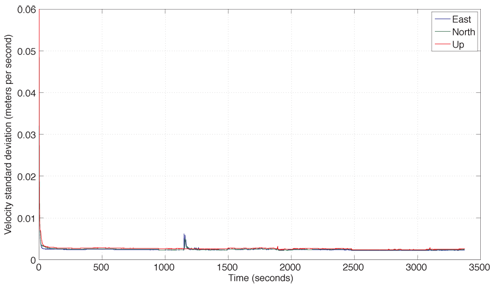
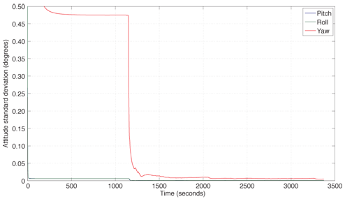
Figure 4. The trajectory of the vehicle in the NTF testFigure 5. The standard deviation of position in the test.Figure 6. The standard deviation of velocity in the test.Figure 7. The standard deviation of attitude in the test.
In Figures 5-7, it can be seen that the standard deviations of position and velocity are less than 0.02 meters and 0.01 meters per second respectively. The standard deviations of pitch and roll angles are less than 0.001 degrees as well as that of yaw, which is less than 0.01 degrees after the vehicle starts to move, at about the 1500th second.
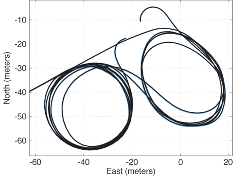
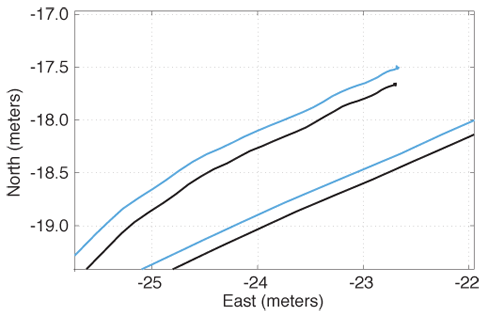
The Locata data was post-processed using Locata’s Integrated Navigation Engine (LINE). It provides an unsmoothed single point position using carrier-phase measurements. The initial ambiguity bias was resolved using the data from the GPS carrier-phase position. Following this initialization, the Locata solution was computed independently of GPS. A 15-meter tower LocataLite location in the vicinity of the start and end of the test (indicated by the “figure eight” pattern in FIGURE 8) allowed sufficient geometry for 3D positioning using Locata. For the rest of the data where there was insufficient vertical geometry, GPS height aiding was used. Figures 8 and 9 show the independent Locata and GPS solutions (without lever arm correction) for the section of the trajectory in the vicinity and the end of the test, respectively. The Locata solution compared to the GPS solution to within a few centimeters for the entire trajectory.
Figure 8. Section of trajectory showing independent Locata solution (black) vs. GPS (blue) with no lever-arm correction.Figure 9. End of trajectory showing independent Locata solution (black) vs. GPS (blue) with no lever-arm correction.
To test the GPS/INS/Locata integration, some GPS observation epochs were deleted to simulate two GPS blockages from seconds of week 94100 to 94250 and from 94500 to 94600. The INS standalone navigation errors with this deleted GPS data were about 8 meters and 2.6 meters, respectively.
In the final GPS/INS/Locata integration test, Locata compensated for the missing GPS data. The integration result was almost identical to the GPS/INS integration result obtained with the original GPS observed data clearly showing that the Locata system could seamlessly replace GPS in this scenario.
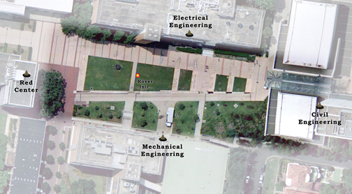
Test 2: Electric Car. Early in 2007, UNSW researchers established a permanent LocataNet on the university campus to provide a research and test facility at UNSW devoted to the Locata technology. The LocataNet setup at UNSW is illustrated in FIGURE 10. It consists of four dual-frequency LocataLites situated on tops of four buildings surrounding a lawn test area. The master LocataLite is on the Civil Engineering building and the other three LocataLites are synchronized to it.
Figure 10. LocataLites on the UNSW campus.
Currently, to be able to obtain a carrier-phase position solution with Locata, the initial ambiguities need to be resolved by initializing the rover receiver on a known position. For this purpose, a point in the middle of the test area was surveyed, and the coordinates were used to initialize the Locata receiver.
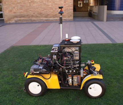
SNAP Lab has developed a small electric car that can be driven using an attached handheld controller (see FIGURE 11). The controller enables the car to move in both forward and reverse and to steer the front wheels.
Figure 11. The electronic car used in the test.
For these tests, the same mounting platform as the one used in the previous experiment allowed all the sensors and ancillary equipment to be attached to the car. For this experiment, we used the following equipment: a Locata receiver, two GPS receivers, a tactical grade INS, a 360-degree prism (tracked by a robotic total station), and two time-sync FPGA data-logging devices.
The starting position was the known point in the middle of the Locata network. The car was then driven in a circular path three times before finishing back at the starting position.
During the test the raw data stream from the Locata receiver, the GPS receivers, and the INS were recorded using the time-sync data-logging devices. In addition, a robotic total station (RTS), which was set up at the edge of the test area, automatically tracked the prism position (the data was recorded internally).
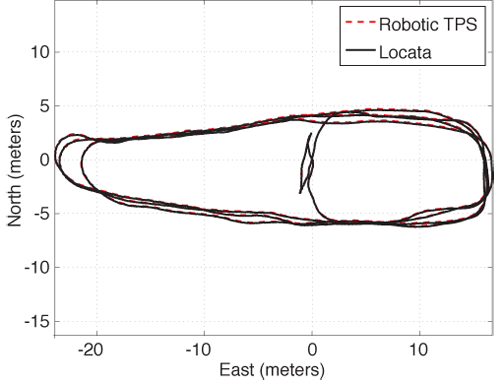
The Locata data was post-processed using LINE to give a single point unsmoothed carrier-phase solution. The initial ambiguity bias was resolved using the data from the GPS carrier-phase position. Following this initialization, the Locata solution was computed independently of GPS. Where there was insufficient vertical geometry (at the very west end of the trajectory shown in FIGURE 12), GPS height aiding was used. The Locata-only solution and the RTS result are shown in Figure 12. The two solutions compare to within a few centimeters of each other.
Figure 12. The trajectory from the Locata-only and robotic total station solutions.
We then carried out the integrated GPS/INS processing. To test the GPS/INS/Locata integration, two GPS outages were simulated by simply removing the data from the GPS file, between seconds of week 103703 and 103713 and 103834 and 103844, respectively.
We then carried out the integrated GPS/INS processing. To test the GPS/INS/Locata integration, two GPS outages were simulated by simply removing the data from the GPS file, between seconds of week 103703 and 103713 and 103834 and 103844, respectively.
In comparison to the original GPS/INS integration, the standalone INS solution has errors of about 35 meters and 12 meters during the first and second outages, respectively.
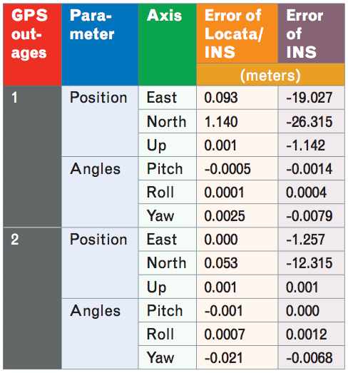
The Locata/INS integration significantly reduced the navigation error during the GPS outages, as summarized in TABLE 2.
Table 2. The difference between the Locata/INS solution and the original GPS/ INS solution
From Table 2 it can be seen that 3D position differences between the Locata/INS and the original GPS/INS integration result have been reduced to 1.143 meters and 0.053 meters during the two GPS outages, respectively. However, the improvement in the accuracy of the attitude angles is not obvious because a 10-second GPS outage is not long enough to cause a significant INS drift.
Concluding Remarks
The test experiments described here are a demonstration of the proof-of-concept of a triple-integration GPS/INS/Locata system. The navigation results indicate that this sensor combination may support navigation in GPS-denied environments, as long as some partial view of the LocataLites within the network is available. Further development of this triple integration system is being undertaken.
Acknowledgments
The research is funded by the Australian Research Council. This article is based on the paper “A Hybrid System for Navigation in GPS-challenged Environments: A Case Study,” presented at ION GNSS 2008, the 21st International Technical Meeting of the Satellite Division of The Institute of Navigation, Savannah, Georgia, September 16-19, 2008.
Manufacturers
The Numerella test equipment included Locata devices, a Honeywell H-764G navigation-grade INS, a Boeing (now Systron Donner) C-MIGITS II tactical grade INS, and a Leica System 1200 dual-frequency GPS receiver. The UNSW campus test equipment included Locata devices, an Omnistar GPS receiver, a Leica MC500 GPS receiver, a Boeing C-MIGITS II INS, a Leica GRZ4 360-degree prism, and a Leica robotic total station TCRP 1203+.
CHRIS RIZOS is a graduate of the University of New South Wales (UNSW), Sydney, Australia, where he obtained a Ph.D. in satellite geodesy. He is head of the School of Surveying and Spatial Information Systems at UNSW.
DOROTA BRZEZINSKA is a professor and leader of the Satellite Positioning and Inertial Navigation (SPIN) Laboratory at The Ohio State University (OSU) in Columbus, Ohio. She received her M.S. and Ph.D. in geodetic science from OSU.
CHARLES TOTH is a senior research scientist at OSU’s Center for Mapping. He received a Ph.D. in electrical engineering and geo-information sciences from the Technical University of Budapest, Hungary.
ANDREW G. DEMPSTER is the director of research in the School of Surveying and Spatial Information Systems at UNSW.
YONG LI is a senior research fellow at the SNAP Lab. He obtained a Ph.D. in aerospace engineering.
NONIE POLITI is a graduate of the School of Electrical Engineering and Telecommunications at UNSW. He obtained a Bachelor’s degree in Telecommunication Engineering and an M.Eng.Sc. in electronics.
JOEL BARNES is director of navigation R&D for Locata Corporation and is also a senior visiting research fellow at the SNAP Lab.
HONGXING SUN is a post-doctoral researcher in the SPIN Lab. He received a bachelor’s degree in geodesy and M.S. and Ph.D. degrees in photogrammetry from Wuhan University, China.
LEILEI LI is a Ph.D. candidate at Chongqing University, China. He is also a visiting Ph.D. student in the SPIN Lab. He received an M.S. degree in instrument science and technology from Chongqing University.
FURTHER READING
• Locata
“Locata: A New Technology for High Precision Positioning” by N. Politi, Y. Li, F. Khan, M. Choudhury, J. Bertsch, J.W. Cheong, A. Dempster, and C. Rizos in Proceedings of ENC-GNSS 2009, the European Navigation Conference, Naples, Italy, May 3-6, 2009.
“Deploying a Locata Network to Enable Precise Positioning in Urban Canyons” by J.-P. Montillet, G.W. Roberts, C. Hancock, X. Meng, O. Ogundipe, and J. Barnes in Journal of Geodesy, Vol. 83, 2009, pp. 91–103 (doi: 10.1007/s00190-008-0236-7).
“High Accuracy Positioning Using Locata’s Next Generation Technology” by J. Barnes, C. Rizos, M. Kanli, A. Pahwa, D. Small, G. Voigt, N. Gambale, and J. Lamance in Proceedings of ION GNSS 2005, the 18th International Technical Meeting of the Satellite Division of The Institute of Navigation, Long Beach, California, September 13–16, 2005, pp. 2049–2056.
“A Positioning Technology for Classically Difficult GNSS Environments from Locata” by J. Barnes, C. Rizos, M. Kanli, and A. Pahwa in Proceedings of IEEE/ION PLANS 2006, the Position, Location, and Navigation Symposium, San Diego, California, April 25–27, 2006, pp. 715–721.
• Integrated Positioning
“Seamless Navigation Through GPS Outages – A Low-cost GPS/INS Solution” by Y. Li, P. Mumford, and C. Rizos in Inside GNSS, Vol. 3, No. 5, July/August 2008, pp. 39–45.
“Ubiquitous Positioning: Anyone, Anything: Anytime, Anywhere” by X. Meng, A. Dodson, T. Moore, and G. Roberts in GPS World, Vol. 18, No. 6, June 2007, pp. 60–65.
“Photogrammetry for Mobile Mapping: Bridging Degraded GPS/INS Performance in Urban Centers” by T. Hassan, C. Ellum, S. Nassar, W. Cheng, and N. El-Sheimy in GPS World, Vol. 18, No. 3, March 2007, pp. 44–48.
“Development of a GPS/INS Integrated System on the Field Programmable Gate Array Platform” by Y. Li, P. Mumford, J. Wang, and C. Rizos in Proceedings of ION GNSS 2006, the 19th International Technical Meeting of the Satellite Division of The Institute of Navigation, Fort Worth, Texas, September 26–30, 2006, pp. 2222–2231.
“An Integrated Positioning System: GPS + INS + Pseudolites” by Y. Yi, D. Grejner-Brzezinska, C. Toth, J. Wang, and C. Rizos in GPS World, Vol. 14, No. 7, July 2003, pp. 42–49.
• Kalman Filtering for Integrated Systems
“Tightly-coupled GPS/INS Integration Using Unscented Kalman Filter and Particle Filter” by Y. Yi and D.A. Grejner-Brzezinska in Proceedings of ION GNSS 2006, the 19th International Technical Meeting of the Satellite Division of The Institute of Navigation, Fort Worth, Texas, September 26–30, 2006, pp. 2182–2191.
“Low-cost Tightly Coupled GPS/INS Integration Based on a Nonlinear Kalman Filtering Design” by Y. Li, J. Wang, C. Rizos, P. Mumford, and W. Ding in Proceedings of NTM 2006, the National Technical Meeting of The Institute of Navigation, Monterey, California, January 18–20, 2006, pp. 958–966.
• Data Time Synchronization
“A Time-synchronisation Device for Tightly Coupled GPS/INS Integration” by P. Mumford, Y. Li, J. Wang, C. Rizos, and W. Ding in Proceedings of IGNSS Symposium 2006, International Global Navigation Satellite Systems Society, Gold Coast, Australia, July 17–21, 2006.
Oxford Technical Solutions (OxTS) has rolled out its Inertial+, an inertial navigation system that can be used with an existing GPS receiver to improve position measurements, according to the company.
The Inertial+ includes inertial sensors, processing engine, and algorithms. It is built around a 6-axis inertial measurement unit — including three angular rate sensors (gyros) and three servo-grade accelerometers — to measure position and velocity even when GPS is not available, OxTS said.
Designed for surveying in an urban environment, the Inertial+ is able to ignore or correct jumps in the GPS measurements. In addition to position data when combined with a GPS receiver, the device will also produce measurements like roll, pitch, and heading. Data is read and output in NMEA format, and other formats are supported. By combining an Inertial+ with a high-accuracy real-time kinematic (RTK) GPS receiver, users can achieve 1 centimeter precision, 0.03 degrees roll/pitch accuracy, and low drift rates when GPS is not available, according to the company.
 Tersus GNSS Inc. is now offering the INS-T-306, a GNSS-aided inertial navigation system. The INS-T-306 is the advanced module that combines GPS L1/L2, GLONASS, BDS navigation and a high-performance strap-down system. It is capable of determining position, velocity and absolute orientation (heading, pitch and roll) for any device on which it is mounted.