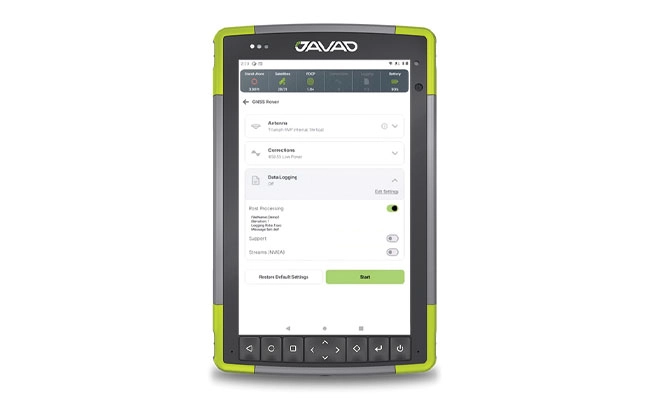
JAVAD Data Collector (JDC) is designed to run seamlessly on any Android device and interface seamlessly with JAVAD GNSS smart antennas. JDC features simple, intuitive workflows that require minimal training, making it accessible for users of all skill levels.
The software includes a Signal Bar for a quick view of receiver status, ensuring users can easily monitor their equipment’s performance. Its easy navigation allows users to move through the software efficiently. It is designed to streamline operations of customers ranging from individual surveyors to large surveying firms, making it easier to deploy and manage receivers across teams of any size with minimal training. JDC is available for download through the company website.
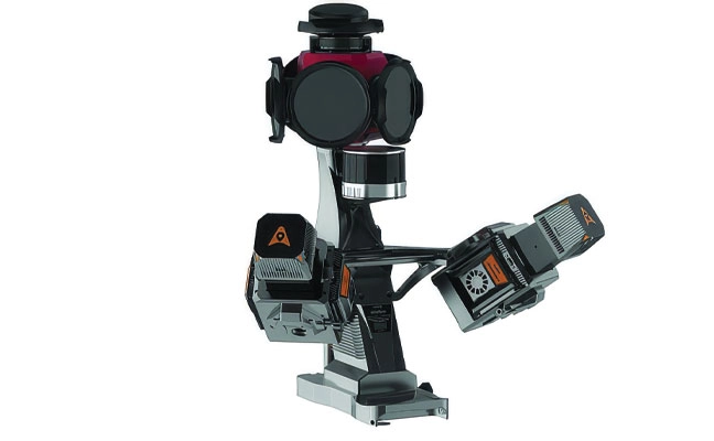
The AU20 MMS is a vehicle-mounted mobile mapping system designed for accurate and efficient collection of 3D spatial data. It combines high-performance lidar technology, versatile sensor support and intelligent data processing to provide a practical and flexible solution for professionals in road surveying, asset management and infrastructure documentation. Its lidar system uses fourth-generation real-time waveform processing to achieve a scan rate of 2 million points per second and 200 revolutions per second, producing point cloud data with 5 mm accuracy and 3 mm precision. This level of detail allows for the identification of fine surface characteristics and features, supporting comprehensive asset inventories and condition assessments. The system’s long-range, multi-cycle laser technology enables high-density data capture up to 250 m in vehicle-mounted applications.
GLONASS satellites traditionally use L1 and L2 frequency division multiple access (FDMA) signals. FDMA is characterized by a different transmit frequency for each satellite. Newer satellite generations also transmit an L3 code division multiple access (CDMA) signal. CDMA uses the same frequency but different ranging codes for individual satellites. The first GLONASS K2 satellite, with the space vehicle number R803, was launched in August 2023. It extends the range of CDMA signals to the L1 and L2 bands.
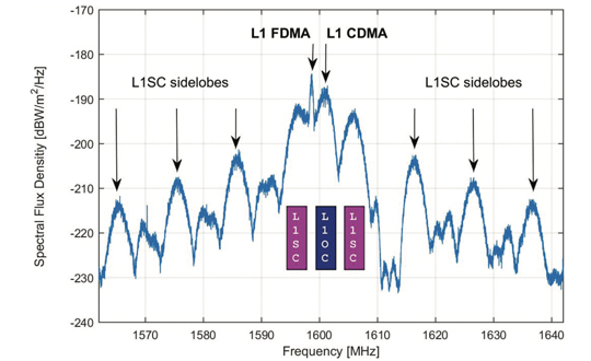
Figure 1. GLONASS K2 spectrum of the L1 frequency band. The different components of the L1 CDMA signal are indicated by colored boxes. L1SC: secured signal. L1OC: open service signal. (All figures provided by the authors)
Frequency spectra of R803, including these new signals, are shown in Figures 1 and 2. They were measured with the 30 m high-gain antenna of the German Space Operations Center (GSOC) in Weilheim, Germany, on Jan. 17, 2024. The largest and sharpest peak in the L1 band at 1,598.625 MHz originates from the 0.5 MHz binary phase-shift keying (BPSK) FDMA signal. The center peak of the L1 CDMA signal is located at 1,600.995 MHz. It is related to the L1 open service signal consisting of a data component (L1OCd) and a pilot component (L1OCp). L1OCd and L1OCp are combined by time-division multiplexing. The peaks that are ±5 MHz away from the L1 CDMA center frequency are introduced by the binary offset carrier (BOC) modulation of the secured L1SC signal. Prominent L1SC side lobes are visible ±15, ±25 and ±35 MHz offset from the center frequency. A quadrature phase-shift keying (QPSK) modulation is used to combine the L1OC and L1SC signals. The local minimum between 1,610 MHz and 1,614 MHz is caused by a notch filter onboard the satellite to protect radio astronomical observations of the Hydroxyl spectral line at 1,612 MHz.
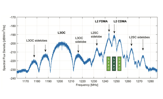
Figure 2. GLONASS K2 spectrum of the L2 and L3 frequency bands. The different components of the L2 CDMA signal are indicated by colored boxes. L2SC: secured signal. L2xC stands for the time multiplexed L2OCp and L2 CSI signal. (All figures provided by the authors)
The L2 CDMA signal is composed of a signal for service information (L2 CSI) and the pilot open service navigation signal (L2OCp). As for L1, these two signals are time-division multiplexed and combined with the secured L2SC signal by QPSK. The left main lobe of the L2SC signals coincides with the L2 FDMA center frequency of 1,243.375 MHz. Both, the L2 CSI, as well as the L2OCp signal, contribute to the peak at the L2 CDMA center frequency at 1,248.06 MHz. The L3 CDMA signal is composed of 10 MHz BPSK data (L3OCd) and pilot (L3OCp) components resulting in a broad peak at 1,202.025 MHz.
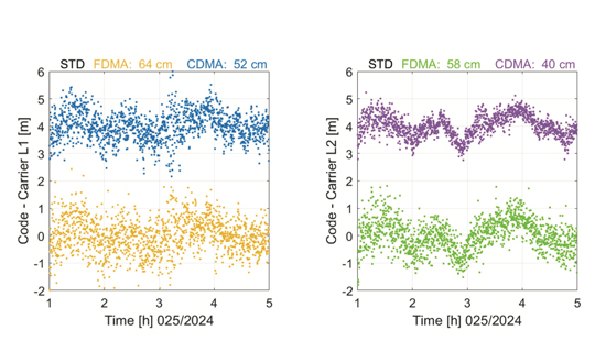
FDMA and CDMA signals of GLONASS R803 were tracked with a JAVAD TRE_3S receiver with a prototype firmware located at GSOC in Oberpfaffenhofen, Germany. Figure 3 shows the differences between pseudo range and carrier phase observations for the FDMA and CDMA signals in the L1 and L2 frequency bands. Long-term ionospheric effects were removed by a second-order polynomial. Thus, remaining effects include short-term ionospheric variations, multipath, and observation noise. The standard deviation of the code–carrier combination is, in general, at the half-meter level. Due to their advanced design, the CDMA signals show an improved performance by 18% for L1 and even 31% for L2 compared to the legacy FDMA signals.
Figure 3. Code – carrier for GLONASS R803 FDMA and CDMA signals: L1 (left) and L2 (right). A second order polynomial has been removed and the CDMA signals are shifted by 4 m. (All figures provided by the authors)
Further launches of L1 and L2 CDMA-capable GLONASS K2 satellites are planned for the upcoming years. A constellation of at least 12 satellites is expected for 2030. To guarantee backwards compatibility, these satellites will also transmit the L1 and L2 FDMA signals. Further improvements in positioning accuracy are expected due to improved satellite clocks and inter-satellite laser ranging.
Russian Space Systems (2016), GLONASS Interface Control Document: Code Division Multiple Access Open Service Navigation Signal in L1 frequency band. Russian Rocket and Space Engineering and Information Systems Corporation, Joint Stock Company.
Russian Space Systems (2016), GLONASS Interface Control Document: Code Division Multiple Access Open Service Navigation Signal in L2 frequency band. Russian Rocket and Space Engineering and Information Systems Corporation, Joint Stock Company.
Manufacturers
GNSS data used in this article were collected with a JAVAD TRE_3S receiver. The spectral overviews were captured with a Rohde & Schwarz FSQ26 signal analyzer.
Javad GNSS’ Javad Ashjaee offers a rundown on the company’s Triumph-F1 unmanned aerial vehicle at Intergeo 2017, which took place Sept. 26-28 in Berlin, Germany. According to the company, the Triumph-F1 is a field-tested high-precision geodetic GNSS receiver that includes four battery compartments, four angled documentation cameras and more.
GLONASS 701K, the first GLONASS-K1 satellite, launched on February 26, 2011, has been reactivated on frequency channel -5. GLONASS 701K, still undergoing flight tests, had previously been active, transmitting legacy FDMA signals on channel -5 between April 8 and October 10, 2011, using almanac slot 4 although the satellite was (and still is) physically in/near orbital slot 21. Transmissions resumed on October 31, 2011, using almanac slot 3, and ceased again on November 30, 2011. During these tests, the satellite was set unhealthy in the broadcast almanac.
GLONASS 701K does not currently appear in the broadcast almanacs but its broadcast ephemeris gives its designation as 26 or R26 in IGS nomenclature.
Some receivers may not currently track GLONASS 701K (also known as GLONASS 801 by the IGS to distinguish the satellite from an earlier GLONASS-M satellite also numbered 701) given that it is not in the almanacs and/or has a non-orthodox slot number. Some software providing conversions between receiver data formats and RINEX formats may not recognize the satellite either.
However, according to reports, at least Javad receivers can successfully track the satellite at the moment.
The reactivation of GLONASS 701K may be a hint that plans to expand the GLONASS constellation from 24 to 30 satellites, as previously reported, are actually underway.
Thanks to T.S. Kelso and Javad Ashjaee for information concerning the reactivation of the satellite.