Tag: lidar

  • Ford Autonomous Vehicle On the Way, CEO Says

    Ford Autonomous Vehicle On the Way, CEO Says

     Mark Fields, President and CEO, Ford Motor Company, delivers the opening keynote address at the 2015 International CES. (Photo by: Sam VarnHagen/Ford)
    Mark Fields, President and CEO, Ford Motor Company, delivers the opening keynote address at the 2015 International CES. (Photo by: Sam VarnHagen/Ford)

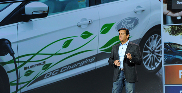
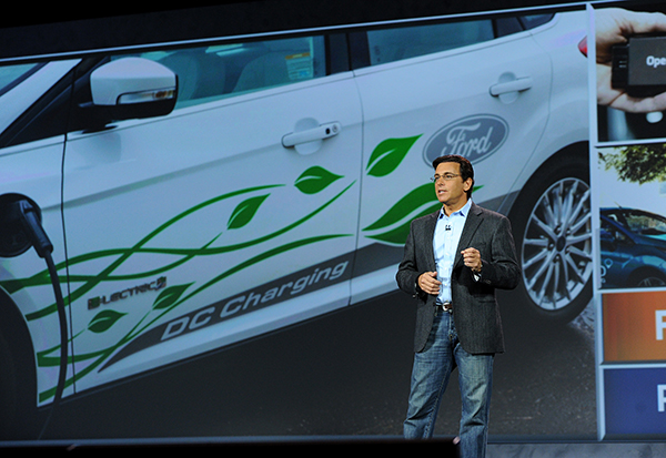
    Ford Motor Company highlighted the semi-autonomous vehicles it has on the road today and fully autonomous vehicles now in development at the 2015 Consumer Electronics Show in Las Vegas this week.

    “We’re already manufacturing and selling semi-autonomous vehicles that use software and sensors to steer into both parallel and perpendicular parking spaces, adjust speed based on traffic flow or apply the brakes in an emergency,” said Raj Nair, Ford chief technical officer and group vice president, Global Product Development. “There will be a Ford autonomous vehicle in the future, and we take putting one on the road very seriously.”

    Ford’s semi-autonomous vehicle features available today include lane-keeping assist, adaptive cruise control, Pre-Collision Assist with Pedestrian Detection and active park assist — with Traffic Jam Assist coming.

    A fully autonomous Ford Fusion Hybrid research vehicle is undergoing road testing. The vehicle uses the same semi-autonomous technology in Ford vehicles today, while adding four LiDAR sensors to generate a real-time 3D map of the surrounding environment.

    The vehicle can sense objects around it using the LiDAR sensors, and uses advanced algorithms to help it learn to predict where vehicles and pedestrians might move.

    “Our priority is not in making marketing claims or being in a race for the first autonomous car on the road,” Fields said. “Our priority is in making the first Ford autonomous vehicle accessible to the masses and truly enhancing customers’ lives.”

    Ford Smart Mobility

    The automaker also laid out its Ford Smart Mobility plan for connectivity, mobility, autonomous vehicles, the customer experience and big data. Included are 25 experiments set for this year — eight in North America, nine in Europe and Africa, seven in Asia and one in South America.

    Each experiment is designed to anticipate what customers will want and need in tomorrow’s transportation ecosystem. “We see a world where vehicles talk to one another, drivers and vehicles communicate with the city infrastructure to relieve congestion, and people routinely share vehicles or multiple forms of transportation for their daily commute,”said Ford President and CEO Mark Fields.  “The experiments we’re undertaking today will lead to an all-new model of transportation and mobility within the next 10 years and beyond.”

    The 25 experiments address four global megatrends — explosive population growth, an expanding middle class, air quality and public health concerns, and changing customer attitudes and priorities — challenging today’s transportation model and limiting personal mobility, especially in urban areas.

    Fourteen of the 25 experiments are Ford-led research projects, and 11 are part of the company’s Innovate Mobility Challenge Series. The experiments include:

    With the Innovate Mobility Challenge Series, Ford invited innovators and developers around the world to create solutions for specific mobility challenges in North America and South America, Portugal, Africa, India, China, England and Australia. Challenges included finding technology solutions to identify open parking spaces in urban areas, better ways to navigate crowded cities and the use of navigation and other tools to help people gain access to medical care in remote areas.

    SYNC 3

    Also at CES, Ford is demonstrating SYNC 3, the company’s new communications and entertainment system that is faster, more intuitive and easier to use with enhanced response to driver commands. SYNC 3 has more conversational speech recognition technology, a more smartphone-like touch screen and easy-to-read graphics to help drivers connect and control their smartphone while on the road.

    The next-generation system builds on the capability of SYNC technology already in more than 10 million vehicles on the road globally. SYNC 3 begins arriving on new vehicles this year.

    “Ford is delivering an easier way for customers to stay connected,” said Nair. “SYNC 3 is another step forward in delivering connectivity features customers most want, and they tell us this kind of technology is an important part of their decision to buy our vehicles.”

    “Even as we showcase connected cars and share our plans for autonomous vehicles, we are here at CES with a higher purpose,” Fields said. “We are driving innovation in every part of our business to be both a product and mobility company — and, ultimately, to change the way the world moves just as our founder Henry Ford did 111 years ago.”

  • L’Avion Jaune Selects Septentrio’s RTK Technology for UAV Laser Scanner

    L’Avion Jaune Selects Septentrio’s RTK Technology for UAV Laser Scanner

    NR_Yellowscan_Ax-m_picture Photo: L’Avion Jaune
    Photo: L’Avion Jaune

    L’Avion Jaune, a service provider and airborne sensors integrator in the field of aerial surveys, has selected the Septentrio AsteRx-m to equip its YellowScan unmanned aerial system. L’Avion Jaune chose the AsteRx-m for its robustness and low-power consumption, Septentrio said.

    YellowScan is the a lightweight all-in-one solution designed to deliver quality aerial surveys carried out using a LiDAR sensor aboard UAVs. The self-contained system integrates into a small package all the necessary equipment for conducting airborne surveys: a 3D laser scanner, an AHRS, a controller, an autonomous power supply module and the AsteRx-m, a high-performance precision GNSS receiver.

    The AsteRx-m provides a compact and low-power solution for precise positioning in difficult environments where the tracking of both GLONASS and GPS satellites allows the receiver to improve the availability and robustness of a positioning solution. Septentrio’s newest RTK models optimally adapt to situations where GNSS signals can be distorted by reflective surfaces and feature unique countermeasures to disturbances, maintaining accurate and stable measurements wherever and whenever centimeter-level accuracy is needed, the company said.

    “The easy-to-integrate AsteRx-m has proven to deliver the most reliable and stable RTK performance of all, in a compact and exceptionally low-power consumption module,” said Michel Assenbaum, CEO of L’Avion Jaune. “The AsteRx-m allows us to extend the operational range and capabilities of the YellowScan, a fully autonomous surveying solution dedicated to UAVs. We have tested the solution in various environments across the world and have never seen it falter.”

    “We are delighted that L’Avion Jaune, a respected expert in designing unmanned-aerial remote sensing solutions, has validated the excellent performance of our ultra-compact GNSS receiver,” said Jan Van Hees, head of business development at Septentrio. “We are impressed to see how much interest YellowScan has drawn since its introduction and we are very proud to be contributing to the success of a best of breed solution in this highly competitive market.”

  • Riegl Launches RiCopter UAV at InterGeo

    At InterGeo 2014, James Van Rens, chief executive officer of Riegl, explains the launch of the RiCopter UAV with LiDAR integration, and its designer gives a live demonstration of the UAV in flight. The show was held October 7-9 in Berlin.

    The unmanned aerial vehicle is a survey-grade unmanned scanning platform for a variety of demanding applications, such as corridor, power line, or railway mapping.

    The high-performance UAV can be equipped with the Riegl VUX-1 survey-grade LiDAR sensor to offer a fully integrated turnkey solution. The RiCopter platform design includes a fully integrated Riegl VUX LiDAR sensor, IMU/ GNSS unit with antenna, control unit, and up to four optional cameras providing measuring characteristics of a 330-degree field of view, 500,000 measurements per second, and 10-millimeter accuracy.

    The class 1 unmanned aircraft system can be flown at a maximum operating altitude of 550 meters with a maximum take-off mass of up to 25 kg and a maximum payload of 16 kg, providing a long flight endurance of 30 minutes.

    RiCopter flight characteristics are smooth and stable in hovering positions, as well as on demanding flight maneuvers under challenging conditions.

    See more InterGeo videos at GPS World’s YouTube Channel.

    Another video of the RiCopter in action comes from Riegl:

  • Eagle Mapping Expands into Large-Area Projects with Airborne LiDAR

    The Riegl LMS-Q1560 airborne laser scanner.
    The Riegl LMS-Q1560 airborne laser scanner.

    Eagle Mapping Ltd., a North American digital airborne mapping company, is now using the new Riegl LMS-Q1560 airborne laser scanner system. Designed to capture ultra-wide swaths and complex environments, the high-performance Riegl LiDAR will enable Eagle Mapping to expand into new markets including large-area, forestry and urban mapping applications for governments and first-nation organizations.

    “The Riegl LMS-Q1560 is a powerful laser scanner developed to acquire data over large geographic areas at high altitudes,” said James Hume, Eagle Mapping President. “This will allow us to map expansive cities, counties and tribal lands quickly and cost effectively.”

    Riegl designed the powerful dual-channel LMS-Q1560 laser scanner with integrated medium-format camera for a variety of airborne mapping projects with an emphasis on wide-swath coverage. With a 58-degree field of view, the laser can be operated at a maximum pulse repetition rate of 800 kHz capable of measuring 530,000 points per second on the ground from an altitude up to 15,500 feet AGL.

    “The Riegl LMS-Q1560 is the most cost-competitive airborne laser scanner on the market today,” said Hume. “We can fly at a higher altitude and collect a denser spacing of elevation data than any other LiDAR system out there.”

    In addition, the Riegl LMS-Q1560 has a forward-and-look capability which, when combined with its wide field of view, enables the device to capture data from multiple angles effectively and accurately at an extremely high point density. The sensor also utilizes Multiple-Time-Around processing, echo digitization and waveform analysis to simultaneously track more than 10 pulses in the air.

    This means the LiDAR can collect tightly spaced elevation points even in complex environments. Examples are built-up city centers with a variety of buildings and vertical structures, as well as extremely rugged mountain terrain where elevations change dramatically and abruptly.

    “Whether working in the mountains of British Columbia or over a densely developed urban center, we will capture accurate elevation points between soaring peaks as efficiently as we do between high-rise office buildings,” added Hume. “And regardless of the terrain, we’ll collect more data in a day and finish jobs faster than we could before.”

    Over nearly three decades, Eagle Mapping has built its reputation on finding more accurate and affordable mapping technologies. Focusing primarily on the global mining industry, the Vancouver firm was among the first to deploy airborne LiDAR technology for mapping. More recently, the Canadian firm configured a high-density, narrow-swath Riegl VQ-580 LiDAR with a DiMAC medium-format camera on a single aircraft to simultaneously collect elevation and image data for efficient mapping of pipeline and transmission line corridors.

    “As we expand into urban and large-area projects for government clients, we will continue to support our extensive client base in the international mining and corridor mapping markets,” said Rodney Cope, vice president of sales and marketing.

    Eagle Mapping operates a Cessna 206 and Piper Navajo aircraft based in British Columbia. The Navajo carries the new Riegl LMSQ1560, and the Cessna is equipped with the Riegl VQ-580 LiDAR and DiMAC digital camera. The firm maintains field offices in Bellingham, Washington, USA, and Medellin, Colombia, in South America.

  • Why Data from Automated Vehicles Needs Serious Protection

    Concerns about data privacy aren’t going away and, in fact, are growing. Many retailers that have adopted in-store tracking technology to enhance shopping experiences and gather information on customer behavior have met with backlash. Increasingly, people are turning to a new crop of apps to safeguard how personal information is used in other apps. We have apps to guard other apps. The world is getting more confused and scary. The Heartbleed bug and other threats have heightened concern about an even more threatening vulnerability of our connected world. So how will drivers feel about increasingly automated vehicles that generate huge masses of data of an exceedingly personal nature? What happens when it is hacked?

    Automated vehicles require multiple types of sensors to obtain information about the vehicle, its movement, and the surrounding environment, which includes the roadway, other vehicles, obstacles and infrastructure. All sorts of ambient information may be captured. Perhaps activity outside of your house, or your kids on their way to school, or the licenses of cars in your driveway will be caught on camera.

    The massive amount of data collected needs to be crunched, and only some of it will be processed within the vehicle. Other captured data will be sent off-board to the cloud for handling, with results then returned to the vehicle. The amount of data that will be created by automated vehicles is uncertain, but I’ve seen estimates of 1 GB per second. Whatever it is, it will be immense.

    What’s collecting data in a driverless vehicle? Lidar, a laser technology that uses reflected light, is identifying everything around the vehicle with great precision. Cameras are taking pictures to detect phases of traffic lights, identify stop signs, and map road lane markings. GPS is tracking the location of the vehicles and helping with navigation. Sonar is detecting objects and measuring their distance, speed and direction. And each vehicle is exchanging positioning, braking, heading and speed data with other vehicles on the road to prevent collisions.

    The data generated is both of a critical and personal nature. And data that is moving in and out of the vehicle to be processed elsewhere or to communicate with other vehicles is particularly vulnerable. The consequences are far greater than a violation of privacy or a stolen identity. The operation of vehicles is at risk to be maliciously disrupted to disastrous outcome. This isn’t an issue we can put off until driverless vehicles are closer in reach. Vehicles today are increasingly equipped with safety and entertainment features that capture critical or sensitive data, any of which could present a threat in the wrong hands.


  • Trimble Launches New Airborne LiDAR Systems

    Trimble's AX60i aerial imaging system.
    Trimble’s AX60i aerial imaging system.

    Trimble is adding to its airborne LiDAR portfolio with the Trimble AX60i and AX80. Both are highly capable, versatile systems that meet the demands of aerial survey operators for corridor and wide area mapping projects, Trimble said.

    The new airborne systems, together with flight planning and analysis software tools, have been designed to provide rapid and efficient point cloud capture as well as high-resolution images and proven workflows with high productivity. The systems can be installed on either fixed wing or rotary aircraft.

    Designed for low-altitude corridor mapping applications, the Trimble AX60i is an entry-level LiDAR system built on the same versatile platform as the high-altitude AX60 system, Trimble said. The platform allows AX60i users to upgrade to an AX60 in the future. The AX60i can be operated up to 5,000 feet above ground level (AGL) while offering a 400-kHz laser pulse repetition rate (PRR) with a single-channel, downward-looking laser.

    The Trimble AX80 is a dual-channel LiDAR system that can be operated up to 15,500 feet AGL and is designed for the most demanding survey applications from high-altitude wide area mapping to detailed low-altitude corridor mapping. The AX80 offers an 800-kHz PRR with revolutionary forward- and backward-looking capability to enhance point density on the ground and improve image resolution. This two-dimensional oblique view offers unparalleled scanning of vertical facades of structures.

    Trimble's AX80 aerial imaging system.
    Trimble’s AX80 aerial imaging system.

    An optional, fully-calibrated 80-Megapixel camera with forward motion compensation can be added to the AX60i and AX80 systems. The camera is integrated into the sensor head package and harmonized with the laser sub-system so that it does not need re-calibration each time the system is fitted to an aircraft.

    These systems are optimized for precision applications, providing a uniform distribution of laser points across the entire field-of-view to widen the usable swath width. Operators can reduce track overlap or duplication, or fly at higher altitudes to achieve a given resolution. Together with a high-precision positioning system, integral power supplies and an in-flight monitoring tool, the Trimble AX60i and AX80 can allow operators to lower the complexity of airborne LIDAR surveys while increasing the quality of the output.

    “The Trimble AX60i and AX80 systems extend our portfolio of aerial imaging solutions to meet a variety of mapping applications,” said Phil Sawarynski, business area director of Imaging Solutions for Trimble’s Geospatial Division. “They have been designed as true end-to-end solutions and are delivered with Trimble flight planning software and Trimble Inpho analysis software. Because everything is supplied by Trimble, operators can have confidence that the complete solution works together properly, and that the flight planning and post-mission analysis suites will enable them to provide a high-quality service to their customers.”

  • Trimble Launches New Geospatial Solutions for Aerial Imaging

    Trimble announced today new additions to its aerial imaging portfolio — the Trimble AX60, a new airborne LIDAR system; and an updated version of its Inpho processing software.

    The announcement was made today at Intergeo 2013, being held this week in Essen, Germany.

    The Trimble AX60.
    The Trimble AX60.

    The Trimble AX60 is a versatile system that can be operated at up to 15,500 feet above ground level (AGL), which meets the requirements for aerial survey projects such as wide area mapping, corridor mapping and remote sensing. Together with integrated flight planning and analysis software tools, the platform has been specifically designed as end-to-end solution that provides enhanced mission flexibility, rapid and efficient point cloud capture, excellent resolution, in-service reliability and high-productivity workflows. The Trimble AX60 can be installed on either fixed wing or rotary aircraft.

    The AX60 has a 400-kHz laser pulse repetition rate (PRR) with a single channel downward-looking laser. An optional, fully calibrated 80-megapixel camera with forward motion compensation can be added. The camera is integrated into the sensor head package and harmonized with the laser system so that it does not need re-calibration each time the solution is fitted to an aircraft. Another key feature is Trimble’s rotating polygon mirror technology for beam deflection that can allow survey missions to be completed faster. This technology provides higher accuracy and a uniform distribution of laser points across the entire field-of-view to widen the usable swath width. Operators can reduce track overlap or duplication, or fly at higher altitudes to achieve a given resolution. Together with a high precision positioning system, integral power supplies, and an in-flight monitoring tool, the Trimble AX60 can allow operators to lower the complexity of airborne LIDAR surveys while increasing the quality of the output.

    “The performance, operational flexibility and reliability of the Trimble AX60 make it an ideal solution for aerial survey companies,” said Phil Sawarynski, business area director of Imaging Solutions for Trimble’s Geospatial Division. “In addition, the Trimble AX60 has been designed as a true end-to-end solution, which includes field-proven Trimble flight planning software and Trimble Inpho analysis software. Since the hardware and software are all supplied by Trimble, operators can have confidence that the complete solution works together seamlessly, and that the flight planning and post-mission analysis suites can enable them to provide a high quality service to their customers.”

    In conjunction with the new airborne laser scanner launch, Trimble also announced its Inpho version 5.6 processing software suite. Version 5.6 now includes the UASMaster module, which has been designed for the complete processing of data acquired by remote piloted aircraft systems (RPAS/UAS). The module georeferences RPAS/UAS images and generates point clouds and othophoto mosaics that allow users to create high quality deliverables for CAD and GIS applications. The UASMaster module is fully compatible with Inpho photogrammetric software modules.

    The Trimble AX60 solution is expected to be available in the first quarter of 2014 through Trimble’s Geospatial Division distribution network. The Inpho version 5.6 and UASMaster is expected to be available in the fourth quarter of 2013.

  • GRW Purchases Optech Gemini ALTM LiDAR Sensor

    GRW has purchased an Optech Gemini Airborne Laser Terrain Mapper (ALTM), adding to the company’s full realm of geospatial mapping solutions, including Digital Aerial Photography, Aerial LiDAR, ground-based Stationary Terrestrial Laser Scanning (STLS), and Mobile Terrestrial Laser Scanning (MTLS).

    “The Optech Gemini will meet the increased demand for aerial acquisition, providing our clients with the latest advancements in LiDAR technology,” said Jeremy Mullins, CP, GRW’s LiDAR manager. “We have seen a substantial growth in the LiDAR market over the last several years.”

    Ben Fister, PE, PLS, PSM, is principal‐in‐charge of the firm’s Geospatial Division. “GRW has always been committed to providing our clients with the best available solutions tailored to their project goals. After careful evaluation, we appreciate the technical advancements that the Optech Gemini has provided in the field of advanced aerial LiDAR solutions. It is a perfect addition to GRW’s arsenal of equipment,” Fister said.

    The sensor will be utilized for a variety of projects and industries, including aviation, coal, forestry, transportation, 3D engineering design projects, and related federal, state, and municipal mapping projects.

  • Autodesk Introduces ReCap, a Free Tool to Create 3D Images from Digital Photos

    Autodesk announces ReCap, a free, key addition to the complete 2014 portfolio of Suites which is a family software and services on the desktop and in the cloud to create intelligent 3D data from captured photos and laser scans in a streamlined workflow. Autodesk ReCap brings together laser scanning and photogrammetry into one streamlined process. In addition, it provides the visualization quality and scalability to handle extremely large data sets.

    AutodeskReCap

    According to the announcement, the Autodesk ReCap product line comprises two main offerings – Autodesk ReCap Studio and Autodesk ReCap Photo. Autodesk ReCap Studio makes it easy to clean, organize and visualize massive datasets captured from reality. Autodesk ReCap Photo helps users create high-resolution textured 3D models from photos using the power of cloud computing. Rather than beginning with a blank screen, Autodesk ReCap now enables any designer, architect or engineer to add, modify, validate and document their design process in context from existing environments.

    For example, a civil engineer can bypass an existing bridge or expand the road underneath digitally and test feasibility. At construction phase, builders can run clash detection to understand if utilities will be in the way. Urban planners can get answers to specific design questions about large areas, such as how much building roof surface is covered by shadow or vegetation.

    ReCap Studio is a data preparation environment that runs on the desktop. Users can import captured data directly into Autodesk design solutions, such as AutoCAD, Autodesk Revit, Autodesk Inventor, etc., to conduct QA and verification of data. The data can come from non-intelligent, black and white sparse point clouds to intelligent, visually high appealing content. ReCap Studio will ship in Autodesk product and suite installers or be available for free on the Autodesk Exchange Apps store.

    ReCap Photo is an Autodesk 360 service designed to create high resolution 3D data from photos to enable users to visualize and share 3D data. By leveraging the power of the cloud to process and store massive data files, users can upload images on Autodesk 360 and instantly create a 3D mesh model. ReCap Photo is available with Standard Suites entitlement and higher.

    Key features of Autodesk ReCap include:

    Visualize and edit massive datasets: On the desktop, ReCap users can view and edit billions of points to prepare them for use in Autodesk portfolio products to enable realistic in context design work
    Professional-Grade Photo to 3D Features: ReCap unlocks the power of ubiquitous cameras to capture high-quality 3D models, bringing reality capture within reach of anyone with a camera. ReCap supports objects of any size and range, full resolution for high-density meshes, survey points and multiple file exports.
    Photo and Laser: ReCap incorporates the best of both photo and laser data capture so that customers can use photos to fill in holes or augment laser scan data. Users can both increase photos scene accuracy with laser points and add photo-realistic detail to laser scans. Create point clouds from photos, align scans and photos and convert professional grade photo to 3D models.
    Autodesk continues to invest in developing sophisticated, easy-to-use reality capture technologies. The company has made several key acquisitions including Alice Labs and Allpoint Systems as well as applied its own research and development resources to accelerate the mainstream adoption of these technologies. As customers are looking for ways to easily and accurately capture the world around them, Autodesk ReCap streamlines Reality Capture workflows, making working with Reality Capture data easy, quick and cost effective.

    Autodesk reports that it combines laser scanning data and photogrammetry into one product family to address and streamline the entire workflow. Whereas traditional point clouds appear as dots, Autodesk technology can now visualize truly massive point clouds as realistic surfaces. Unique to Autodesk is that users can interact with these huge data sets doing CAD-like operations such as selection, tagging, moving, measuring, clash detection, and object extraction, all with native points. Laser scanning and photogrammetry are historically very expensive and data intensive. Autodesk’s goal is to democratize the process of reality capture so that anyone can capture the world around them to create high quality 3D models.

  • Blue Marble Releases Global Energy Mapper Version 14.1

    Blue Marble Geographics has announced the release of Global Energy Mapper 14.1, making available a variety of enhancements in the its GIS tool for energy professionals. This update to the company’s desktop GIS software offers  new and improved features and functions, including a significant improvement in the ability to process massive amounts of LiDAR point cloud data, jumping from tens of millions of points to hundreds of millions. B

    lue Marble’s geospatial data manipulation, visualization and conversion solutions are used worldwide by thousands of GIS analysts at software, oil and gas, mining, civil engineering, surveying, and technology companies, as well as governmental and university organizations.

    Global Energy Mapper 14.1 provides a dramatic increase in LiDAR processing and display speed and the ability to view and process point files in the hundreds of millions range, Blue Marble said. This is beneficial for previewing the data before creating a gridded surface model and includes several options for filtering the data during import and for rendering the point cloud to reflect return type or intensity. Improved metadata access provides a detailed statistical breakdown of the point cloud and customizable point size improves on-screen display. Global Mapper Package (.GMP) files are now able to store LiDAR point clouds in a special compressed format, much smaller than uncompressed LAS data and on par with the best compression available today. This allows LiDAR data to be efficiently archived or shared with other Global Mapper users.

    Global Energy Mapper 14.1 also provides a new tool for creating whisker lines emanating from a selected point or points, useful for seismic survey coverage. Whisker lines are often used to estimate coverage from selected points to see if a point in a seismic survey covers what is needed. There is also a new digitizer tool for easily subdividing an existing area into four separate areas that is useful for subdividing parcels or properties.

    Version 14.1 includes an enhancement to the Site Pad Placement tool so users can create a site pad for a non-level surface. There are also speed improvements when accessing Spatial On Demand data from our partner Spatial Energy, along with new built in point types for oil and gas symbology, Blue Marble said. Additionally USB dongle licensing is now available for GEM with this release.

    “We are excited to be offering this significant upgrade to our Global Energy Mapper customers,” stated Blue Marble President Patrick Cunningham. “We are confident our users in the oil and gas and other energy sectors will be impressed with the improvements in processing LiDAR point clouds along with the new energy specific tools.”

  • Indianapolis Awards Multi-Million Dollar Mapping Contract to Woolpert

    Woolpert announced its Indianapolis office has been awarded two contracts totaling approximately $2 million by the City of Indianapolis Department of Public Works (DPW) to survey pavements and develop a street sign inventory using mobile mapping technology.

    According to the announcement, the project requires collection of data across 3,200 miles of city streets, one of the single largest mobile light detection and ranging (LiDAR) collection efforts to date. LiDAR technology uses pulses from a laser to produce highly accurate measurements and map physical features.

    “We’re proud to be at the front of using this industry-leading technology for a cost-effective approach to collecting data and developing a 3D model of the city. This truly maximizes taxpayers’ dollars by reducing the cost of a data collection effort while also providing us with the data necessary to perform government functions more efficiently, such as street rehabilitation,” said Jeremy Jobe, Woolpert project manager in Indianapolis. “Further, the dataset can be used for safety improvements through viewshed or line-of-sight analysis to proactively identify potential traffic hazards caused by the surrounding environment.”

    Nearly half of the cost associated with the project is being covered through a federal grant, according to Woolpert. The city leveraged this grant to significantly reduce using local dollars for the project. Remaining funds were generated from the RebuildIndy program and other local funding sources.

    Woolpert will use its Optech LYNX M1 Mobile LiDAR system to collect the data and then use that data to develop a street sign database for compliance with Federal Highway Administration’s (FHWA) Manual on Uniform Traffic Control Devices (MUTCD) requirements for sign inventories. This manual provides the U.S. standard for signs, signals and pavement markings.

    “The benefit of using a high-accuracy mobile LiDAR system with survey-grade capabilities on such projects is the rich dataset that it captures from which assets can be extracted, in this case signage,” said Jobe. “The city will not only be able to use the data for its sign database, it will also be able to extract or call on the Woolpert team to extract additional features in the future without remobilizing the team and assuming associated costs or placing additional field crews in harm’s way, which provides the true value in this collection effort.”

    Woolpert will team with VS Engineering and DB Engineering on the sign inventory and Dynatest on the pavement analysis. Upon completion of the project, data will be integrated with the city’s existing computerized maintenance management system.

  • A Comparison of Lidar and Camera-Based Lane Detection Systems

    By Jordan Britt, David Bevly, and Christopher Rose

    Nearly half of all highway fatalities occur from unintended lane departures, which comprise approximately 20,000 deaths annually in the United States.  Studies have shown great promise in reducing unintended lane departures by alerting the driver when they are drifting out of the lane. At the core of these systems is a lane detection method typically based around the use of a vision sensor, such as a lidar (light detection and ranging) or a camera, which attempts to detect the lane markings and determine the position of the vehicle in the lane. Lidar-based lane detection attempts to detect the lane markings based on an increase in reflectivity of the lane markings when compared to the road surface reflectivity. Cameras, however, attempt to detect lane markings by detecting the edges of the lane markings in the image. This project seeks to compare two different lane detection techniques-one using a lidar and the other using a camera. Specifically, this project will analyze the two sensors’ ability to detect lane markings in varying weather scenarios, assess which sensor is best suited for lane detection, and determine scenarios where a camera or a lidar is better suited so that some optimal blending of the two sensors can improve the estimate of the position of the vehicle over a single sensor.

    Lidar-based lane detection

    The specific lidar-based lane detection algorithm for this project is based on fitting an ideal lane model to actual road data, where the ideal lane model is updated with each lidar scan to reflect the current road conditions. Ideally, a lane takes on a profile similar to the 100-averaged lidar reflectivity scans seen in Figure 1 with the corresponding segment.
    Figure 1. Lidar reflectivity scan with corresponding lane markings.

    Note that this profile has a relatively constant area bordered by peaks in the data, where the peaks represent the lane markings and the constant area represents the surface of the road.  An ideal lane model is generated with each lidar scan to mimic this averaged data, where averaging the reflectivity directly in front of the vehicle generates the constant portion and increasing the average road surface reflectivity by 75 percent mimics the lane markings.  This model is then stretched over a range of some minimum expected lane width to some maximum expected lane width, and the minimum RMSE between the ideal lane and the lidar data is assumed to be the area where the lane resides. For additional information on this method, see Britt, Rose & Levy, September 2011.

    Camera-based lane detection

    The camera-based method for this project was built in-house and uses line extraction techniques from the image to detect lane markings and calculate a lateral distance from a second-order polynomial model for the lane marking in image space. A threshold is chosen from the histogram of the image to compensate for differences in lighting, weather, or other non-ideal scenarios for extracting the lane markings. The thresholding operation converts the image into a binary image, which is followed by Canny edge detection. The Hough transform is then used to extract the lines from the image, fill in holes in the lane marking edges, and exclude erroneous edges. Using the slope of the lines, the lines are divided into left or right lane markings. Two criteria based on the assumption that the lane markings do not move significantly within the image from frame to frame are used to further exclude non-lane marking lines in the image. The first test checks that the slope of the line is within a threshold of the slope of the near region of the last frame’s second-order polynomial model. The second test uses boundary lines from the last frame’s second-order polynomial to exclude lines that are not near the current estimate of the polynomial. second-order polynomial interpolation is used on the selected lines’ midpoint and endpoints to determine the coefficients of the polynomial model, and a Kalman filter is used to filter the model to decrease the effect of erroneous polynomial coefficient estimates. Finally, the lateral distance is calculated using the polynomial model on the lowest measurable row of the image (for greater resolution) and a real-distance-to-pixel factor. For more information on this camera-based method, see Britt, et al.


    Figure 2. Camera-based lane detection (green-detected lanes,blue-extracted lane lines, red-rejected lines).

    Testing

    Testing was performed at the NCAT (National Center for Asphalt Technology) in Opelika, Alabama, as seen in Figure 3.  This test track is very representative of highway driving and consists of two lanes bordered by solid lane markings and divided by dashed lane markings.  The 1.7-mile track is divided into 200-foot segments of differing types of asphalt with some areas of missing lane markings and other areas where the lanes are additionally divided by patches of different types and colors of asphalt.


    Figure 3. NCAT Test Facility in Opelika, Alabama.

    A precision survey of each lane marking of the test track as well as precise vehicle positions using RTK GPS were used in order to have a highly accurate measurement of the ability of the lidar and camera to determine the position of the vehicle in the lane. Testing occurred only on the straights, and the performance was analyzed on the ability of the lidar and camera to determine the position of the lane using metrics of mean absolute error (MAE), mean square error (MSE), standard deviation of error (σ­error), and detection rate. The specific scenarios analyzed included varying speeds, varying lighting conditions (noon and dusk/ dawn), rain, and oncoming traffic. Table 1 summarizes the results for these scenarios. For additional results, please see [8].

    Scenario

    MAE(m)

    MSE(m)

    σ­error (m)

    %Det

    Lidar

    Noon Weaving

    0.1818

    0.1108

    0.3076

    98

    Camera

    Noon Weaving

    0.1077

    0.0511

    0.2246

    80

    Lidar

    Dusk 45mph

    0.0967

    0.0176

    0.1245

    100

    Camera

    Dusk 45mph

    0.2021

    0.0592

    0.2433

    57

    Lidar

    Medium Rain

    0.1046

    0.0177

    0.1314

    65

    Camera

    Medium Rain

    0.0885

    0.0101

    0.0635

    91

    Lidar

    Low Beam, Night

    0.0966

    0.0159

    0.1215

    99

    Camera

    Low Beam, Night

    0.1182

    0.0185

    0.0762

    84

    Table 1. Lidar and camera results for various environments.

    Additional testing on the effects of oncoming traffic at night was examined by parking a vehicle on the test track at a known location with the headlights on. Figure 4 shows the lateral error with respect to closing distance where a positive closing distance indicates driving at the parked vehicle, and a negative closing distance indicates driving away from the vehicle. Note that the camera does not report a solution at -200 m, which is due to track conditions and not the parked vehicle.


    Figure 4. Error vs. Closing Distance.

    Based on these findings it would appear that the camera provided slightly more accurate measurements than the lidar while having a decrease in detection rate. Additionally the camera performed well in the rain where the lidar experienced decreased detection rates.

    References

    Frank S. Barickman. Lane departure warning system research and test development. Transportation Research Center Inc., (07-0495), 2007.

    J. Kibbel, W. Justus, and K. Furstenberg. using multilayer laserscanner. In Proc. Lane estimation and departure warning Proc. IEEE Intelligent Transportation Systems, pages 607 611, September 13 15, 2005.

    P. Lindner, E. Richter, G. Wanielik, K. Takagi, and A. Isogai. Multi-channel lidar processing for lane detection and estimation. In Proc. 12th International IEEE Conference on Intelligent Transportation Systems ITSC ’09, pages 1 6, October 4 7, 2009.

    K. Dietmayer, N. Kämpchen, K. Fürstenberg, J. Kibbel, W. Justus, and R. Schulz. Advanced Microsystems for Automotive Applications 2005. Heidelberg, 2005.

    C. R. Jung and C. R. Kelber, “A lane departure warning system based on a linear-parabolic lane model,” in Proc. IEEE Intelligent Vehicles Symp, 2004, pp. 891–895.

    C. Jung and C. Kelber, “A lane departure warning system using lateral offset with uncalibrated camera,” in Intelligent Transportation Systems, 2005. Proceedings. 2005 IEEE, sept. 2005, pp. 102 – 107.

    A. Takahashi and Y. Ninomiya, “Model-based lane recognition,” in Proc. IEEE Intelligent Vehicles Symp., 1996, pp. 201–206.

    Jordan Britt, C. Rose, & D. Bevly, “A Comparative Study of Lidar and Camera-based Lane Departure Warning Systems,” Proceedings of ION GNSS 2011, Portland, OR, September 2011.