Furuno Electric and Xona Space Systems have signed a Memorandum of Understanding (MoU) to collaborate on solutions using Xona Pulsar, a low-Earth-orbit positioning, navigation and timing (LEO PNT) service for next-generation satellite navigation.
Through the agreement, both companies will leverage their respective technological expertise and business strengths to explore opportunities for delivering advanced and promising LEO PNT solutions.
Furuno has been actively pursuing LEO PNT as a promising technology capable of complementing or even substituting for GNSS.
LEO PNT refers to systems that use a satellite constellation of 200 to 400 satellites deployed in low Earth orbit at an altitude of 500 km to 2,000 km. The LEO constellation is designed for PNT rather than non-terrestrial networks to provide global positioning and timing services similar to GNSS, but with significantly better performance.
Xona is a pioneer in LEO PNT technology and offers a commercial service called Pulsar, which uses a dedicated LEO PNT constellation of 258 satellites. Compared to conventional GNSS, this service enhances resiliency and improves the accuracy of positioning and timing — the proximity of LEO satellites to Earth makes their signal power about 100 times stronger.
Pulsar adopts a signal architecture similar to GNSS for compatibility, making it easy to integrate into existing GNSS products. Integrating Xona Pulsar into Furuno’s products will provide an alternative to GNSS while significantly boosting performance by complementing existing GNSS services.
Furuno’s Pulsar-enabled timing solutions allow users to maintain accurate synchronization even when GNSS is degraded due to unexpected failures, including jamming and spoofing, the companies said.
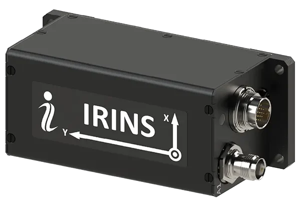
Inertial Labs, a Viavi Solutions Inc. company, has announced IRINS, a low Earth orbit (LEO)-aided inertial navigation system (INS) designed to allow full operation across land, air and sea in GNSS-denied, -degraded and -disrupted space operating environment .
Combining the capabilities of an INS, an altitude and heading reference system (AHRS) and a LEO PNT receiver, this platform marks a major milestone in Viavi’s portfolio for assured positioning, navigation and timing by bringing together the INS capabilities of inertial labs and the timing expertise of Jackson Labs.
The IRINS embedded system has been developed to counter the exponentially rising number of spoofing and jamming attacks that have affected military and critical infrastructure. Now, resilient LEO-based PNT and inertial navigation are available within a fully integrated system from a single vendor.
The system combines an INS, an AHRS and the GNSS-independent STL-2600 LEO Iridium receiver module. These capabilities enable the system to calculate altitude, position, velocity and time data, as well as minimize bias from causing drift. To help detect and eliminate attack signals, the device additionally integrates a GNSS receiver with a controlled reception pattern antenna (CRPA) port.
“The IRINS is the first fruit borne of VIAVI’s visionary strategy to mitigate vulnerabilities in positioning, navigation and timing, bringing together resilient satellite-based timing with tactical-grade IMUs to deliver the most precise PNT for GNSS-denied environments,” said Jamie Marraccini, vice president, Inertial Labs Products, Viavi. “By tightly coupling inertial sensing, LEO-based timing and navigation and anti-jam GNSS technologies into a single platform, the IRINS provides unmatched continuity, accuracy and trust for operations in contested and denied environments.”
“Assured access to PNT is critical for operations in contested environments,” said Maynard Porter, Director, Government PNT Business, Iridium. “Integrating Iridium PNT alongside VIAVI’s INS and AHRS provides users with an exceptionally resilient source of time and location data to maintain operational effectiveness when GNSS signals are disrupted.”
The IRINS is certified for IP67 and MIL-STD-810G environmental requirements. It is based on the company’s fully calibrated tactical-grade MEMS 3-axis accelerometer, gyroscope and clock. These are combined with embedded barometers, magnetometers and an optional onboard air-data computer as part of its AHRS.
Satellite communication is provided through the company’s STL-2600 receiver, which links to the Iridium LEO constellation. All capabilities are housed within a compact 126.5 × 49.3 × 53.3 mm enclosure.
Tokyo-based satellite company ArkEdge Space Inc. has signed letters of intent with three international organizations to develop a PNT satellite network in low-Earth orbit (LEO).
The agreements with TrustPoint Inc., the Royal Institute of Navigation in the United Kingdom and FrontierSI aim to strengthen satellite-based PNT capabilities for civil, commercial and security applications.
The collaboration represents an early phase in ArkEdge Space’s effort to build international partnerships for PNT infrastructure. The company, which designs and operates small satellite constellations, said the project will focus on improving resilience of positioning and timing systems that support critical infrastructure.
The partners plan to examine policy frameworks and national PNT strategies as the project moves into a demonstration phase. ArkEdge Space said it will expand its network of international partners to support the development of space-based positioning systems.
“By working together, this collaboration represents an important step as we accelerate the development of resilient, trusted PNT capabilities that support critical infrastructure and informed decision-making worldwide,” ArkEdge Space CEO Takayoshi Fukuyo said.
TrustPoint has transmitted its first Low-Earth Orbit Navigation System (LEONS) time-transfer and tracking signals from a ground node to spacecraft in orbit. The milestone advances the development of commercial navigation infrastructure independent of GPS.
GNSS satellites require knowledge of their own time and orbital position to provide accurate data to Earth-based users. Most LEO spacecraft currently rely on GPS or medium-Earth orbit (MEO) signals for that information. Interference and jamming are increasingly affecting these LEO connections, degrading or blocking signals.
LEONS provides GPS-independent time transfer and orbit tracking. Initially developed for TrustPoint’s planned constellation, the system can be adapted for other LEO operators requiring timing and navigation for their spacecraft. The ground-to-space infrastructure is designed to support a GPS-independent PNT layer in orbit.
“With the pace of modern threats accelerating, the difference between concepts and capabilities matters,” said Nicole Hilliard, director of government programs at TrustPoint. “This milestone demonstrates that commercial partners can field resilient, GPS-independent PNT capabilities that strengthen national security architectures and justify continued investment in companies that deliver.”
The demonstration supports TrustPoint’s participation in the SpaceWERX AltPNT Challenge, which awarded the company two contracts to develop alternative PNT capabilities. The program seeks to deploy new options for precise, dual-use PNT systems.
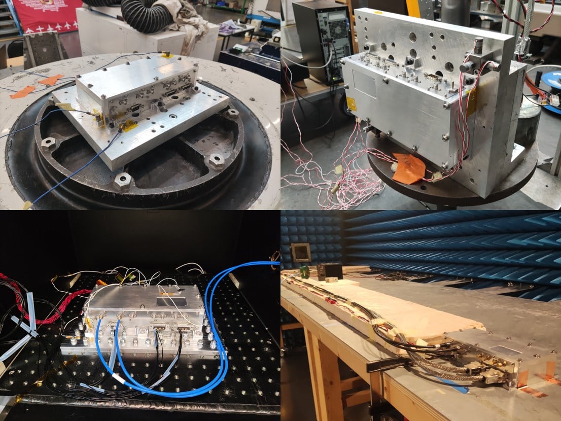
SpacePNT SA, a global provider of high-accuracy, radiation-tolerant spaceborne GNSS receiver equipment for missions ranging from Earth to cislunar orbit, has completed extensive qualification testing of its second-generation product, including vibration, shock, thermal vacuum and electromagnetic compatibility tests.
The multi-frequency, multi-GNSS receiver resulted from two European Space Agency (ESA) ARTES Competitive & Growth (C&G) development projects supported by ESA and the Swiss Space Office.
The first project enabled SpacePNT to develop an industrialized second-generation product for large-scale production targeting low-Earth orbit, LEO position-navigation-timing and geostationary orbit telecommunications constellations. The receiver includes a proprietary Precise Orbit Determination algorithm that provides sub-decimeter real-time positioning and timing aboard spacecraft. The company validated the POD algorithm in a hardware-in-the-loop environment and retrofitted it into two first-generation flight models delivered to a customer for satellite integration.
Under the second project, SpacePNT developed a Radiation Hardiness Assurance approach for long-duration missions in harsh radiation environments. ESA’s GENESIS satellite mission, which will operate in a challenging medium Earth orbit environment, will be the first to use this RHA approach. SpacePNT will supply the mission’s GNSS receiver equipment.
Though the second-generation receiver uses largely the same hardware, software and firmware technology as the company’s flight-proven first-generation product, SpacePNT performed a complete qualification campaign to validate design changes.
After passing all qualification and performance tests, SpacePNT will begin manufacturing first flight models of its second-generation products for several customers. The receivers will fly on demanding Earth observation, in-orbit servicing and space exploration missions at altitudes from LEO through medium Earth orbit, geosynchronous transfer orbit, geostationary orbit and lunar distances.
The views expressed herein do not reflect the official opinion of the European Space Agency.
The National Space Science and Technology Center (NSSTC) and Thales Alenia Space, a joint venture between Thales (67%) and Leonardo (33%), are cooperating to explore opportunities in low-Earth orbit (LEO) space navigation systems.
The growing dependence of economies and daily lives on Global Navigation Satellite Systems is driving innovation and leading to technologies that deliver enhanced resilience and improved performance. At the forefront, low-Earth orbit positioning, navigation and timing (PNT) is emerging as a game-changer.
The LEO-PNT satellites seek to provide guaranteed and sovereign centimeter location accuracy, robustness, resistance against jamming and spoofing, and low latency. LEO-PNT will serve emerging applications such as high-level autonomy cars, including persistent coverage in dense urban areas, unmanned aerial and maritime vehicles, and 5G/6G ground telecommunication network synchronization.
Recognizing the strategic importance of LEO-PNT, the NSSTC is working with Thales Alenia Space to explore opportunities in this domain. The partnership was formalized through the signing of a memorandum of understanding at the Paris Air Show 2025, establishing a framework for cooperation. Building on that foundation, both parties signed an agreement marking the start of joint technical studies and engineering activities focused on regulatory protection and system design elements for LEO-PNT.
The collaboration reflects a vision to explore pathways that can enhance the robustness and sovereignty of future navigation services while deepening international cooperation and knowledge exchange between the United Arab Emirates and Europe in the field of space technology.
“This collaboration marks an important step toward building the UAE’s next-generation navigation capabilities,” said Ali Al Shehhi, director of NSSTC. “LEO-PNT will bring a new level of precision and resilience, and working with Thales Alenia Space allows us to accelerate our path toward a sovereign system that supports the UAE’s long-term strategic vision.”
“LEO-PNT is a game changer in satellite navigation in terms of increased precision, resilience and signal penetration, enabling new applications and economic growth,” said Hervé Derrey, CEO of Thales Alenia Space. “We are proud to offer our expertise in satellite navigation to the NSSTC, thereby strengthening our collaboration with the United Arab Emirates in the space domain.”
The European Space Agency (ESA) has confirmed plans to launch the first two satellites in its low-Earth orbit (LEO) positioning navigation and timing (PNT) constellation in the second half of December 2025. The launch will use a Rocket Lab Electron Vehicle, marking Europe’s first venture into LEO-based satellite navigation.
The LEO-PNT in-orbit demonstrator mission, called Celeste, aims to test satellite navigation capabilities in LEO and evaluate its integration with existing medium-Earth orbit (MEO) systems.
Celeste features a constellation of ten satellites that will fly close to Earth to test innovative signals across various frequency bands. The first two Celeste satellites, built in parallel by GMV and Thales Alenia Space, are set to launch in the coming months.
The dedicated Electron rocket launch will place both satellites in orbit at 510 km altitude. The launch window extends for three months beginning in mid-December 2025, with operations conducted from Rocket Lab’s New Zealand facility.
ESA Director of Navigation, Javier Benedicto, said, “We are thrilled to see the LEO-PNT demonstration advancing so quickly, with less than two years between mission kick-off and launch. This launch ensures the first European LEO-PNT satellites are in space before spring 2026, crucial for bringing the frequencies into use in compliance with the International Telecommunications Union.”
Galileo’s “Daughter Mission”
The name Celeste pays homage to Maria Celeste, Galileo Galilei’s daughter, as the two shared a strong emotional and intellectual bond, with the daughter honoring her father’s astronomical interest. This symbolic connection links the pioneering work of the father of modern astronomy to contemporary navigation systems, with Celeste serving as a bridge between Galileo’s groundbreaking discoveries and today’s satellite-based positioning technology.
The demonstrator satellites for Galileo, launched in 2005 and 2008, were called GIOVE, after the Italian word for Jupiter. This name also paid tribute to Galileo’s achievements in discovering the planet’s four largest Moons which were used to determine longitude from anywhere on Earth.
System Advantages
The initial Pathfinder A satellites are CubeSats measuring 12U and 16U formats, comparable to suitcase size and weighing approximately 20 kg to 30 kg. These satellites will broadcast in L-band and S-band frequencies and operate for at least six months following orbital commissioning.
The larger, more complex Pathfinder B satellites will follow, incorporating additional payloads to test innovative signals across multiple frequency bands and demonstrate expanded services.
LEO-PNT satellites will supplement existing GNSS constellations by providing enhanced coverage in challenging environments. The system aims to improve navigation services in deep urban areas, under heavy foliage, in polar regions and potentially indoor locations where current MEO satellites face limitations.
The complete demonstrator constellation, expected to be operational by 2027, will assess how LEO navigation systems can integrate with existing GNSS infrastructure. The mission will also test interoperability with 5G and 6G communication standards.
Preparing for Launch
Satellite integration and testing of Pathfinder A hardware and software continues ahead of the December launch. ESA and industrial teams plan to complete testing during summer 2025, with qualification and acceptance reviews scheduled for autumn.
“Pathfinder A satellites have already paid off, even before launch,” said Roberto Prieto-Cerdeira, ESA’S LEO-PNT project manager. “The experience gathered during their development is helping to identify critical technologies, system design trade-offs, design choices and optimised approaches and processes, paving the way for future phases of LEO-PNT. Having them in orbit and validating their signals and algorithms is a major additional achievement.”
Future Plans
Following the demonstrator mission, ESA plans to propose an in-orbit preparatory phase at the agency’s November Ministerial Council meeting. This phase would focus on technology development and industrialization, potentially leading to an operational system integrated with EU GNSS infrastructure.
The Celeste demonstrator is part of FutureNAV, an ESA Navigation program designed to maintain Europe’s position at the forefront of satellite navigation technology.
The mission receives backing from 15 ESA member states: Austria, Belgium, Finland, France, Germany, Hungary, Italy, Norway, Poland, Portugal, Romania, Spain, Sweden, Switzerland and the United Kingdom. More than 50 entities from 14 countries participate in the two development consortia awarded contracts in 2024.
PNT services are integral to industries worldwide, from logistics and telecommunications to critical infrastructure. The rise of LEO satellites is set to revolutionize this space, overcoming limitations of traditional GNSS, such as vulnerability to interference and limited urban coverage, according to FrontierSI.
Key insights from the report, which is the first in a series of annual reports, include:
Industry impacts: How LEO PNT addresses GNSS vulnerabilities, offering more robust and accurate navigation solutions.
Government and regulatory challenges: The rise of commercial PNT players necessitates collaboration to address interoperability, spectrum management and governance issues.
Business innovation opportunities: Critical sectors such as logistics and autonomous systems stand to benefit from assured and precise PNT services.
Investment potential: The nascent stage of the LEO PNT market presents opportunities for investors to identify game-changing technologies and key players.
The report is recommended for professionals and organizations deeply engaged in satellite navigation, including:
Engineers, designers and project managers in the space and defense industries
Autonomous systems manufacturers
Policymakers and regulatory bodies responsible for satellite navigation and spectrum management
Commercial stakeholders in telecommunications, transport and logistics
Academics, researchers and analysts with an interest in satellite navigation technologies
Investors analyzing the growth potential of LEO PNT solutions
Providers of critical infrastructure reliant on precise timing synchronization
The LEO PNT State of the Market Report aims to provide stakeholders with the necessary insights to navigate this transformative period for PNT.
The European Space Agency (ESA) will host the first FutureNAV Industry Day on Feb. 18, 2025 — at ESTEC, the Netherlands — to address the growing demand for advanced positioning, navigation and timing (PNT) technologies. This event aims to bring together European stakeholders in satellite navigation to discuss future developments and foster collaboration within PNT and GNSS sectors.
As the leading system developer and design authority for Galileo and EGNOS, ESA plays a crucial role in Europe’s satellite navigation landscape. The agency launched the FutureNAV program in 2022 to unify efforts in advancing navigation technologies. Two key missions under this initiative are low-Earth orbit (LEO) PNT, which will demonstrate the potential of navigation satellites in LEO and Genesis, which will combine four geodetic techniques in one satellite to improve Earth’s reference frame.
FutureNAV Industry Day seeks to provide attendees with insights into ESA navigation plans and potential opportunities for European industry. It will follow a Request for Information on LEO-PNT industrialization, gathering information on European production capabilities for payload building blocks and satellite platforms.
To complement these upstream initiatives, the Navigation Innovation and Support Programme (NAVISP) Industry Days will be held at the University of London on March 4-5, 2025, focusing on downstream applications and bringing together industry leaders and innovators.
Click here to register and learn more about the event.
The European Space Agency (ESA) has initiated two navigation missions, Genesis and low-Earth-orbit positioning, navigation and timing (LEO-PNT) as part of its FutureNAV program. ESA has awarded contracts, totaling €233 million, to several European entities to begin the development of the missions. They are designed to address the growing demand for more resilient and precise navigation solutions in Europe.
Genesis, with a contract value of €76.6 million, involves a consortium led by OHB Italia, tasked with the development and operation of the Genesis satellite and its payloads, supported by contributions from Italy, Belgium, France, Switzerland, Hungary and the UK. The satellite is expected to launch in 2028, with subsequent years dedicated to scientific exploitation. Genesis aims to significantly improve the International Terrestrial Reference Frame (ITRF) and offer unprecedented precision for navigation and a myriad of Earth sciences applications.
For the LEO-PNT mission, ESA has distributed €78.4 million for each of the two contracts for the development of in-orbit demonstrators. These LEO-PNT satellites will explore new signals and frequency bands, designed to provide enhanced resilience, accuracy and speed in navigation. The projects are led by GMV Aerospace and Defense and Thales Alenia Space France and involve a broad consortium of more than 50 entities from 14 countries. The first LEO-PNT satellite is expected to launch within 20 months from the project’s commencement, with the complete constellation operational before 2027.
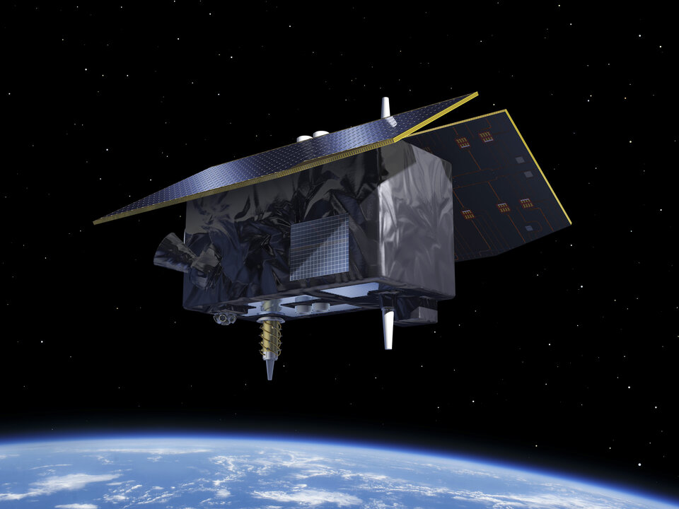
LEO-PNT satellite. (Image: ESA)
Genesis is designed as a flying observatory to refine the ITRF to an accuracy of 1 mm and a stability of 0.1 mm/year, serving as a crucial reference for all space- and ground-based observations. This enhanced reference frame is designed to directly benefit satellite-based systems and applications across various sectors, including aviation, traffic management and autonomous vehicles. It is intended to have have broader implications for meteorology, natural hazard prediction and climate change monitoring.
The LEO-PNT mission aims to establish a small constellation of demonstration satellites to test novel navigation signals and interoperability with GNSS to offer improved signal robustness and extended navigation services to challenging environments such as deep urban areas and indoors. This mission will explore the potential of LEO constellations in supporting a wide range of applications, from transportation and critical infrastructure to mobile devices and asset tracking using advancements in communication standards, such as 5G/6G.
To produce GNSS satellite orbit ephemerides and clock data with high precision and for all constellations, the Navigation Support Office of the European Space Agency’s European Space Operations Centre (ESA/ESOC) continually strives to keep up and improve its precise orbit determination (POD) strategies. As a result of these longstanding efforts, satellite dynamics modeling and GNSS measurement procedures have progressed significantly over the last few years, especially those developed for the European Galileo satellites. Because the accuracy of ESA/ESOC’s GNSS orbits has reached such a high level (about 1 to 3 centimeters), introducing a completely new type of GNSS satellite into the processing is not as easy as it used to be. New spacecraft models – the first and foremost being a model for a satellite’s response to solar radiation pressure (SRP) – are needed for the “newcomer” so that the quality of the overall multi-GNSS solution does not suffer. Just as important are spacecraft system parameters, or metadata, such as the location of the satellite antenna’s electrical phase center and the satellite attitude law.
In this article, we show the efforts we have made at ESA to bring the quality of our orbit estimates for the GPS Block III satellites up to par with those for Galileo and the earlier GPS satellite blocks. We report on the results from on-ground and in-flight determinations of the Block III transmit antenna phase center characteristics up to 17 degrees from the antenna boresight direction. Moreover, we take advantage of the non-zero horizontal offsets of the transmit antenna from the spacecraft’s yaw axis to estimate the satellite yaw angle during Earth eclipse season and present a simple analytical formula for its calculation. Finally, we describe the development and validation of improved radiation force models for the Block III satellites.
We start, however, by giving a brief overview of the GPS Block III program.
GPS BLOCK III
The U.S. Space Force GPS Block III (previously referred to as Block IIIA) is a series of 10 satellites being procured by the United States to bring new future capabilities to both military and civil positioning, navigation, and timing (PNT) users across the globe. Designed and manufactured by defense contractor Lockheed Martin (LM), the satellites are reported to deliver three times better accuracy, 500 times greater transmission power, and an eightfold enhancement in anti-jamming functionality over previous GPS satellite blocks. At ESA/ESOC, we are paying particular attention to this new tranche of satellites as they are the first to broadcast L1C, a new common signal interoperable with other GNSS, including Galileo.
At the time of this writing, there are six GPS III space vehicles (SVs) in orbit. The first one – nicknamed “Vespucci,” in honor of Italian explorer Amerigo Vespucci – lifted off atop a SpaceX Falcon 9 rocket from Cape Canaveral Air Force Station, Florida, in December 2018, and entered service on January 13, 2020. An additional four SVs are expected to be launched soon, before moving on to an updated version called GPS IIIF (“F” for Follow On). The first Block IIIF satellite is projected to be available for launch in 2026.
In view of the growing number of GPS III SVs in orbit, and soon to be joined by IIIFs, accurate spacecraft models and metadata information are becoming more and more important in order to maximize PNT accuracy.
SATELLITE ANTENNA PHASE CENTER PARAMETERS
GNSS signal measurements refer to the electrical phase center of the satellite transmitting antenna, which is neither a physical nor a stable point in space. The variation of the phase center location as a function of the direction of the emitted signal on a specific frequency is what we call the phase center variation (PCV). The mean phase center is usually defined as the point for which the phase of the signal shows the smallest (in a “least-squares” sense) PCV.
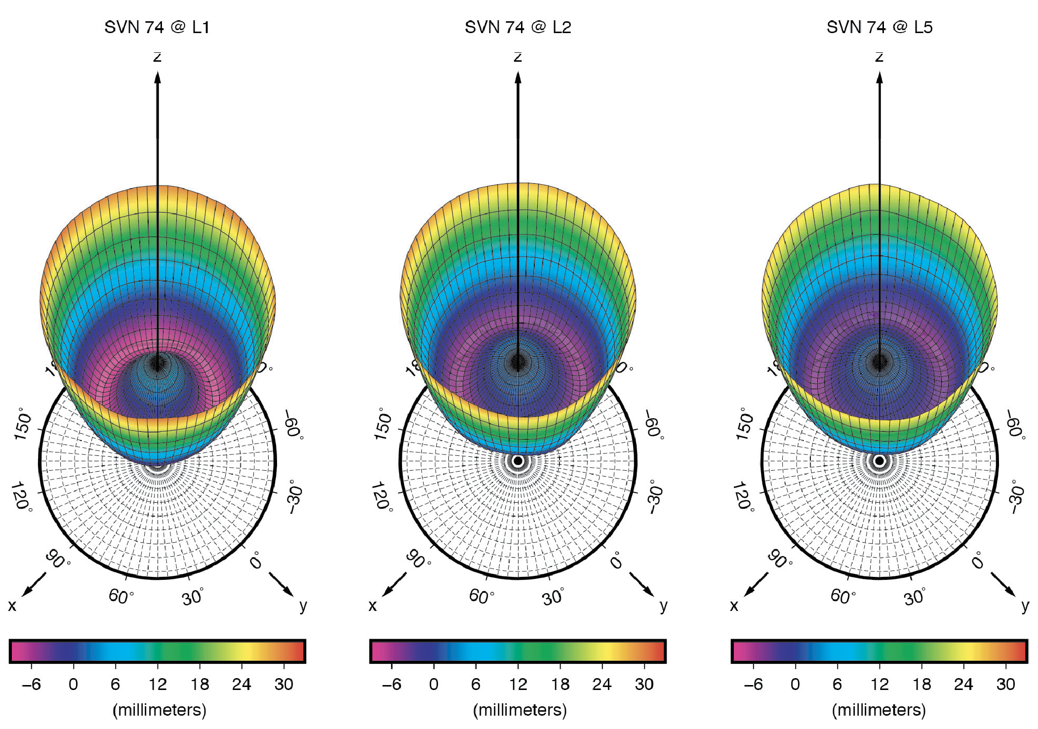
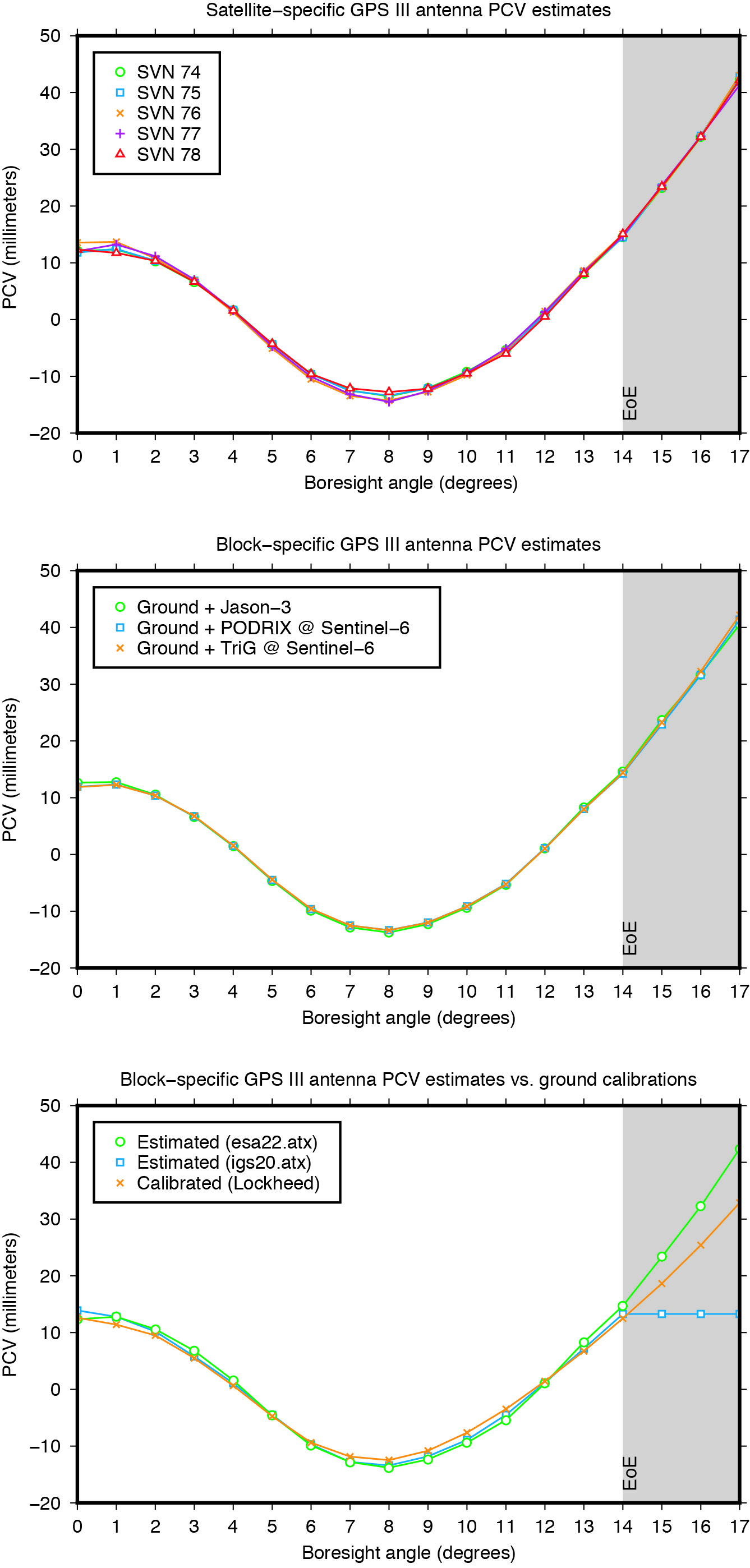
Figure 1: Ground-calibrated GPS Block III transmit antenna phase center variations (PCVs). (All figures provided by the authors).
The point of reference for describing the motion of a satellite, however, is typically the spacecraft center of mass (CoM). The difference between the position of the mean phase center and the CoM is what we typically refer to as the satellite’s antenna phase center offset (PCO). Both PCO and PCV parameters must be precisely known — from either a dedicated on-ground calibration or one performed in flight — so that we can tie our GNSS carrier-phase measurements consistently to the satellites’ CoM.
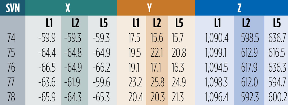
On-Ground Calibrations. Like for previous GPS vehicles, the Block IIR and Block IIR-M satellites, LM has fully calibrated the GPS III transmit antennas prior to launch at their ground test facilities. Antenna offset parameters for all three carrier signals (L1, L2 and L5) were posted on the U.S. Coast Guard Navigation Center (NAVCEN) website (www.navcen.uscg.gov) shortly after each satellite launch. In December 2021, NAVCEN released the PCOs for SV number (SVN) 78, along with updates to the first four satellites (see Table 1). About ten months later, in October 2022, the antenna pattern for each satellite and signal frequency were published (see Figure 1).
Table 1: Ground-calibrated GPS Block III transmit antenna PCOs in millimeters. (Image: GPS World staff)
The December 2021 offsets are referred to as predicted values at the end of year one on orbit. They differ from the previous ones by several centimeters in both vertical (Z) and horizontal (X and Y) directions. Particularly surprising are the X- and Y-PCOs, which were initially reported to be close to zero. The differences in the horizontal PCOs have generated uncertainty and debate, especially within the International GNSS Service (IGS) about which values to adopt for the new antenna model release (igs20.atx). Testing of the two different PCO datasets in our software demonstrated that the non-zero values as given in Table 1 are the significantly more accurate ones. We will return to this later in this article.
Combined Ground- and Space-Based Tracking. In this part of this article, we discuss the combination of dual-frequency tracking data from geodetic-quality GPS receivers in low Earth orbit (LEO) with those from a global receiver network on the ground to determine the phase center parameters of the GPS Block III transmit antennas. The LEO-based measurements were taken by the GNSS receivers on board the ocean altimetry satellites Sentinel-6 Michael Freilich and Jason-3. The 1,336-km altitude of both of these missions enables the estimation of the GPS satellite antenna PCVs from 0 up to 17 degrees from boresight while GPS receivers on Earth can only see the satellites up to a maximum angle of 14 degrees. The 14-degree limit is also referred to as the GPS satellites’ edge of Earth (EoE) angle.
For the modeling of the PCVs we follow the approach of the IGS using piece-wise linear functions of the boresight angle and constraining the PCV values to between 0 and 14 degrees to have zero mean. Furthermore, we employ fully normalized spherical harmonic expansions of degree 8 and order 5 to solve for the azimuth- and elevation-angle-dependent PCVs of the orbiting receiver antennas. The IGS standard antenna phase center corrections from igs20.atx are applied to all terrestrial receiver and GPS Block II transmit antennas.
Figure 2: GPS Block III transmit antenna PCVs as a function of boresight angle. The gray shaded area indicates the angular range that is inaccessible from the ground but relevant to high altitude LEO missions such as Sentinel-6 Michael Freilich or Jason-3.
The estimated Block III antenna PCVs are depicted in Figure 2. The estimates for the five individual antennas match each other to within 0.4 millimeters root-mean-square (RMS) (see Figure 2, top). The agreement among the PCVs that we get when processing the tracking data from each LEO receiver’s antenna separately is at the sub-millimeter level, too (see Figure 2, middle). Overall, the level of consistency suggests that the PCVs are of very good quality and that a block-specific representation is sufficient for precise applications. Comparison of the final block-specific PCV estimates against the values from the current IGS antenna model and from the ground calibrations shows strong agreement (RMS = 0.7 millimeters) between 0 and 14 degrees from boresight (see Figure 2, bottom). Beyond the 14-degree limit, the differences compared to the IGS standard are up to three centimeters, underlying the urgent need for an update of the igs20.atx file.
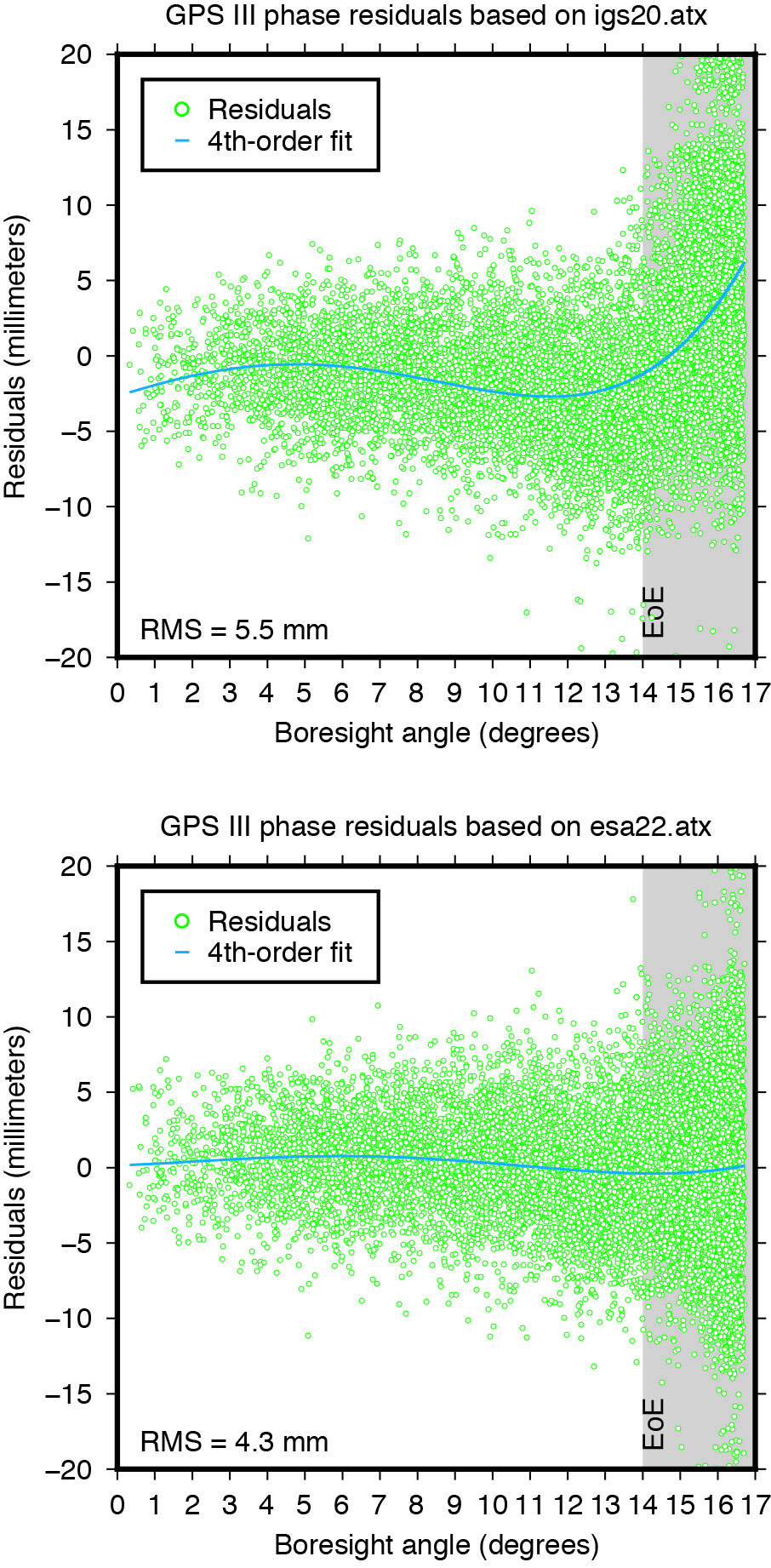
Applying the extended PCV corrections as part of the POD process to the GPS LEO receiver data shows significant improvement in the post-fit carrier-phase residuals when compared to the PCV corrections from the IGS legacy model. It removes a previously existing boresight angle-dependent trend and leads to a more than 20% reduction in the computed residual RMS (see Figure 3).
Figure 3: Post-fit residuals of GPS III carrier-phase data from Sentinel-6 Michael Freilich when using igs20.atx (top) and esa22.atx (bottom), respectively.
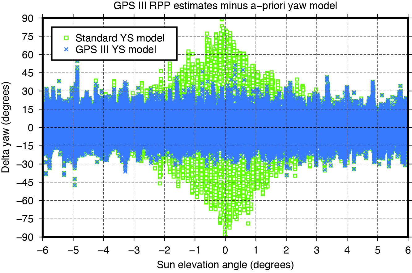
YAW MODELING
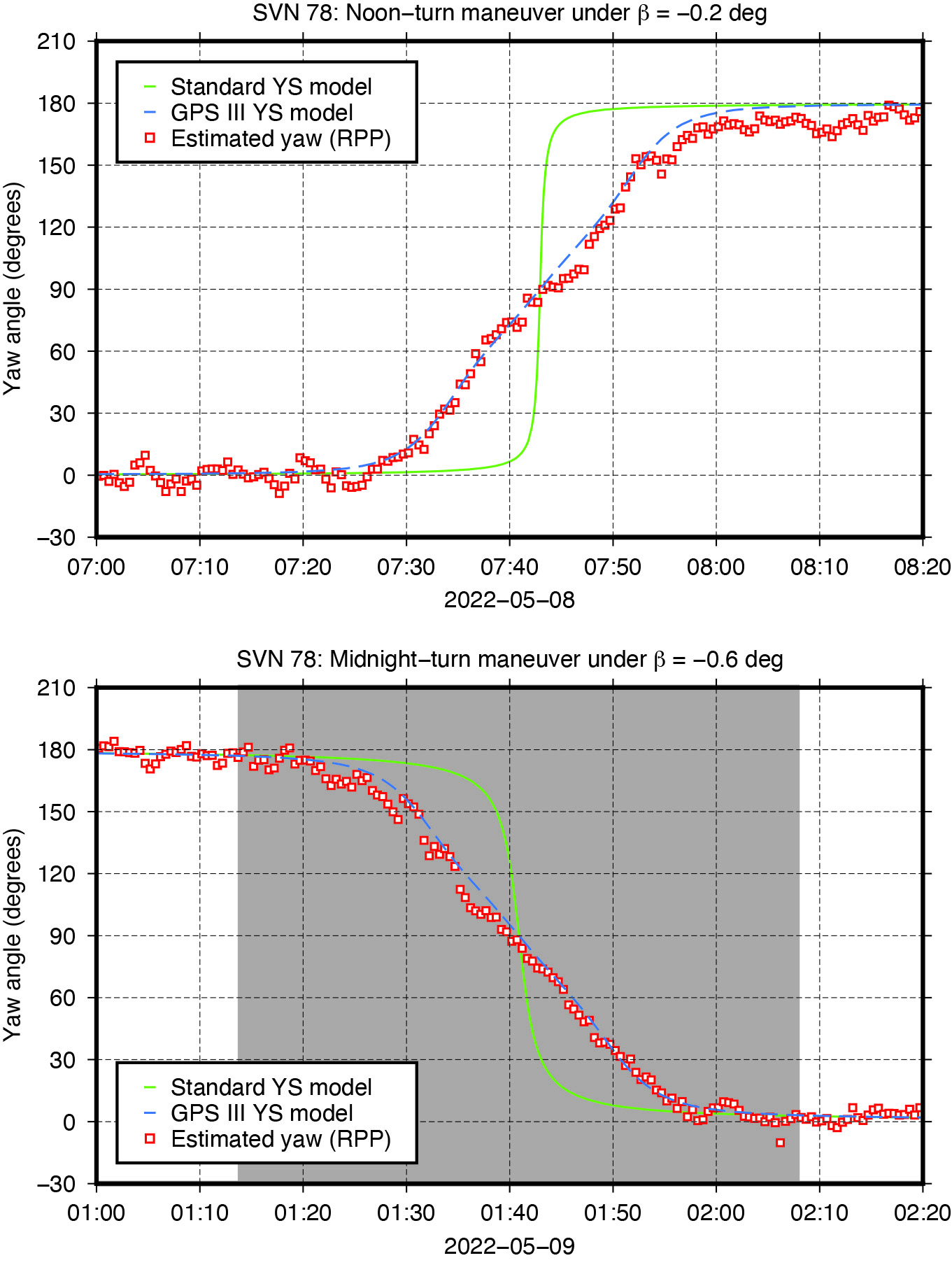
Figure 4: Yaw turn maneuver of GPS Block III satellite SVN 78 near orbit noon (top) and orbit midnight (bottom), respectively.
GNSS satellites cannot follow an ideal yaw-steering whenever the Sun elevation angle relative to the orbital plane (the so-called beta angle) gets too low and the yaw rate required to keep the satellite solar panels pointing towards the Sun exceeds the maximum satellite yaw rate. The strategies on how GNSS satellites perform rate-limited yaw-steering are different for each type of spacecraft and only partly documented for public users. Continuous knowledge of GNSS spacecraft yaw attitude, however, is important for kinematic and dynamic reasons. Errors in yaw are known to affect the modeling of transmit antenna phase center’s position, carrier-phase wind-up, and radiation pressure forces. On the other hand, when the mean antenna phase center location is offset from the spacecraft’s Z-axis, the satellite yaw state can be estimated instantaneously from the tracking data of a global receiver network. The approach behind this is commonly referred to as “upside down” or “reverse kinematic precise point positioning” (RPP). The horizontal antenna offset vector can be viewed here as a kind of rotating lever arm whose length determines the accuracy of the yaw angle estimates. Since the Block III X-offset is just 7 centimeters, one should not expect the same RPP accuracy as for other GNSS satellites like those of the GPS IIF or GLONASS-M series, which have an X-offset that is six (GPS IIF) or even eight (GLONASS-M) times larger.
Nonetheless, with more than three hundred ground stations, kinematic RPP works reasonably well even for GPS III as we can see from Figure 4, which shows the estimated yaw angle of SVN 78 while passing orbit noon and orbit midnight with a Sun elevation angle of almost zero degrees. The plots suggests that Block III satellites — unlike previous Block IIA and IIF SVs — perform their yaw slews near noon and near midnight in the same way and at the same yaw rate. In this respect, the yaw turn behavior is similar to that of the IIR/IIR-M satellites. However, with a maximum yaw rate of 0.10 degrees per second, the Block III satellites rotate only half as fast as those of the IIR/IIR-M family. What is also different is the start time of the yaw maneuver. As can be seen from Figure4, the maneuver does not start when the required yaw rate exceeds the physical limit but already a couple of minutes before.
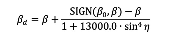
The RPP analysis has led to the development of a simple yaw model for the Block III satellites. For a Sun elevation angle β below β0 = 4.780 degrees, the yaw angle can be approximated with an RMS accuracy of about 8 degrees by the following formula: whereas
is a modified Sun elevation angle, SIGN(β0, β) a FORTRAN function returning the value of β0 with the sign of β, and η is the satellite’s argument of latitude with respect to orbit midnight. The agreement between estimated and modelled yaw angles is illustrated in Figure 5.
Figure 5: Differences between yaw angle estimates and yaw angle models.
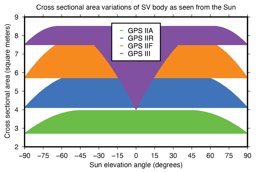
Fourier Series for Radiation Force Modeling. The most critical component determining the shape of a GNSS satellite’s trajectory is SRP – the force caused by the impact of solar photons hitting the satellite’s surfaces. A satellite’s sensitivity to SRP can be characterized by the variation of the cross-sectional area to mass ratio (A/M) of the satellite body as it orbits Earth and the Sun. The greater the change in A/M, the higher the sensitivity. From this perspective, the Block III spacecraft can be considered the most sensitive in GPS history.
Based upon LM’s tried-and-true A2100 bus, the satellite is much more elongated than previous generations. With an estimated size of 7.5 meters squared, the X-side is almost twice as large as the Z-side. Depending on the elevation angle of the Sun relative to the orbital plane, the body’s cross-sectional area exposed to sunlight varies between 4.0 and 8.5 meters squared (See Figure 6). With a nominal on-orbit weight of approximately 2,160 kilograms, this results in a change of A/M of 0.0021 meters squared per kilogram. For comparison, the corresponding values for the previous GPS SVs are 0.0015 (IIF), 0.0017 (IIR), and 0.0013 (IIA) meters squared per kilogram.
Figure 6: Size of GPS satellite body’s cross-sectional area exposed to sunlight.
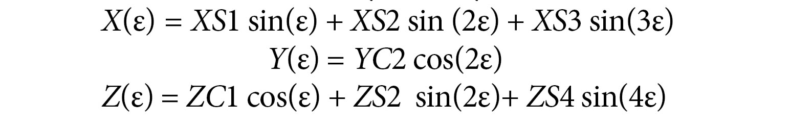
Given the size and shape of Block III spacecraft, an appropriate radiation force model is considered mandatory to achieve the highest orbit accuracy possible. With that said, we empirically derived a set of background force models for the first five GPS III satellites. Our approach rests on dynamical long-arc (9-day) fitting to precise orbit data spanning up to three years and the following low-order Fourier functions of the Earth-spacecraft-Sun angle ε to represent the radiation force in the satellite body-fixed system:
The Fourier coefficients (XS1, XS2, XS3, YC2, ZC1, ZS2 and ZS4) are iteratively adjusted together with initial epoch state, a constant Y-axis bias, and 1‐cycle per revolution along‐track parameters to best fit the orbit data in a least-squares sense. All individual 9-day arc solutions are rigorously combined on a normal equations level to form a robust set of Fourier model coefficients for each satellite or group of satellites.
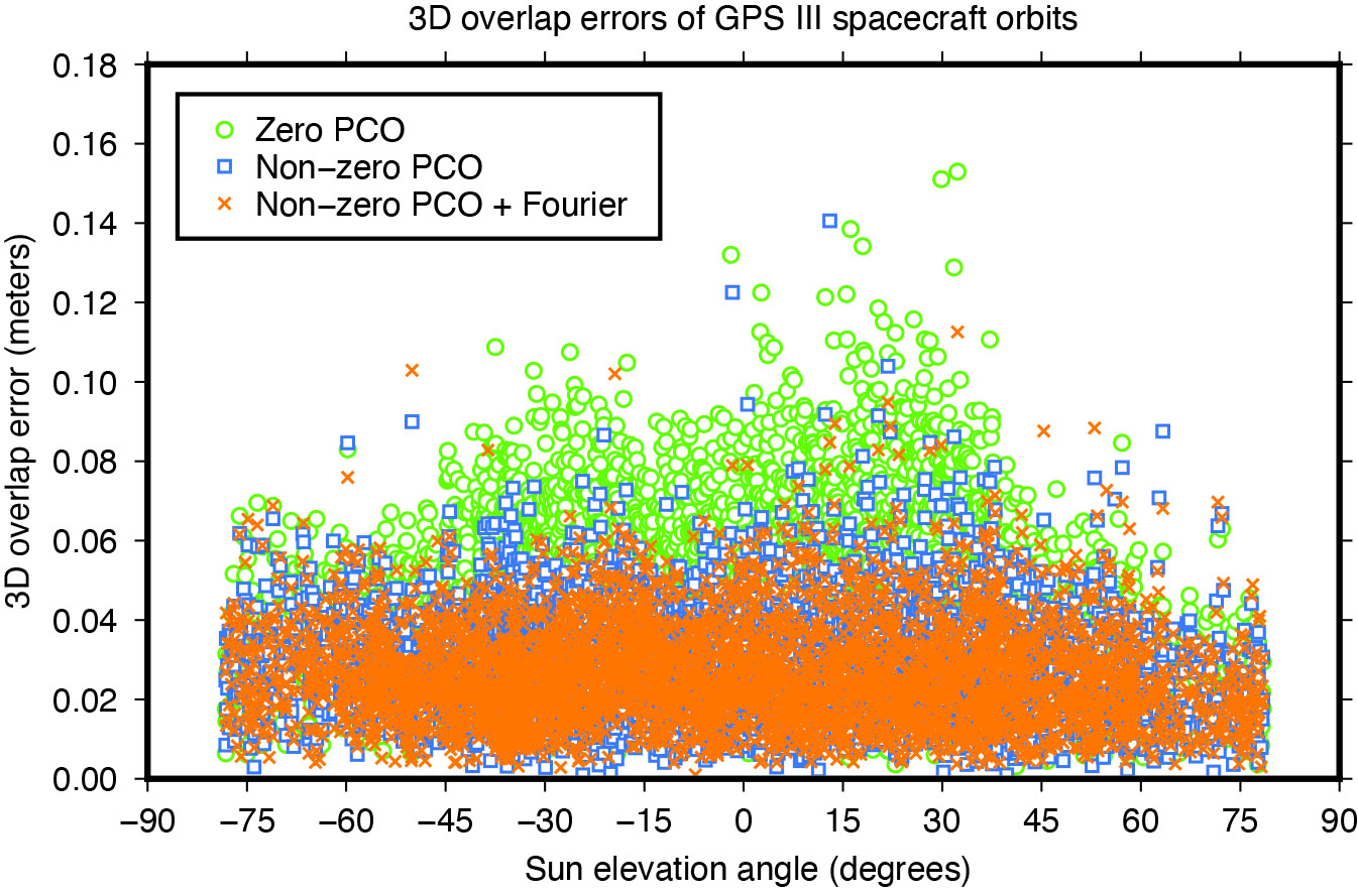
ORBIT OVERLAP TESTS
Figure 7: Impact of horizontal antenna PCOs and Fourier force model on day-boundary orbit overlap errors.
To investigate the effect of the transmit antenna PCOs and the Fourier force models on the satellite orbits, we use our ESA/IGS processing strategy to generate dynamic 24-hour-arc solutions spanning January 2020 to December 2022, first with zero PCO and the non-zero horizontal offsets from Table 1 and no a-priori radiation force model, then with the non-zero offsets and the additional Fourier model in the background. The direct comparison of the generated orbits reveals significant differences for the Block III satellites of about 0.1 meters (3D).
To demonstrate the improved performance of the non-zero offsets and the Fourier model, we take the orbits for successive days and look at the midnight epoch where they overlap. The difference in the orbit position, subsequently referred to as “overlap error,” gives us a worst case estimate of the satellite orbit accuracy. Comparison of the overlap errors provides evidence that the Block III orbits are much more accurate when using the non-zero rather than the zero X and Y PCOs. The overall 3D overlap RMS reduces from 49.5 millimeters (with zero PCOs) down to 32.3 millimeters (with non-zero PCOs). Results for the Sun elevation regions below 45 degrees, in particular, show significant improvement (see Figure 7).
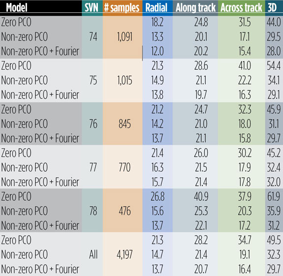
Use of the Fourier model has additional positive impact on the overlaps. Comparing the orbits produced with and without the a-priori radiation force model, we see a decrease in the 3D overlap error RMS from 32.3 to 29.7 millimeters averaged over all satellites. The orbit component that benefits most from both the improved antenna phase and the advanced force modeling is the one normal to the satellite orbital plane (across track). The SVs improving the most are SVN 75 and SVN 78, though significant improvements can be seen for all other satellites too (see Table 2).
Table 2: Day-boundary overlap RMS errors of GPS III spacecraft orbits in millimeters.
EMPIRICAL PARAMETER ESTIMATES
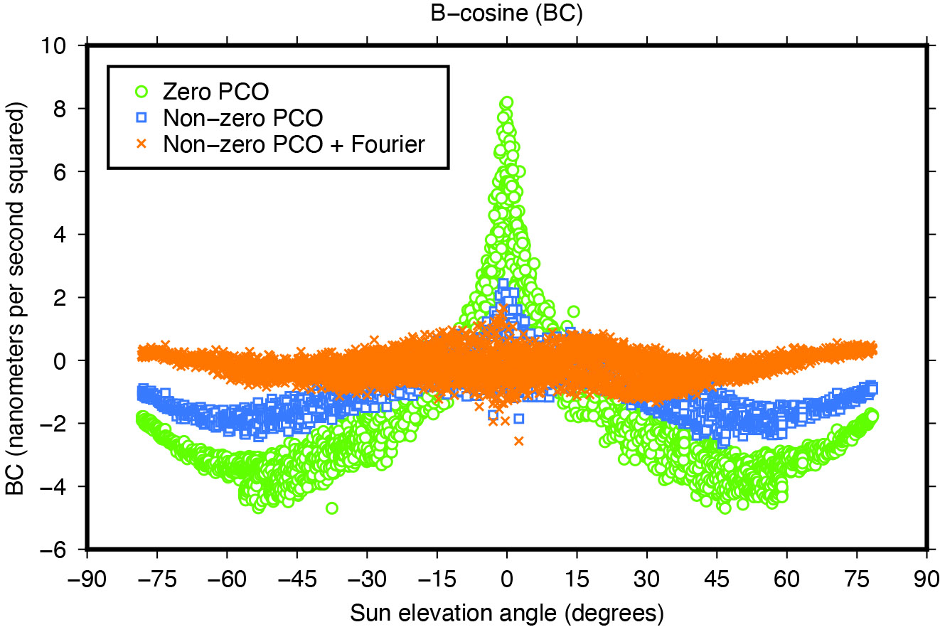
Another means of assessing the quality of spacecraft models is the size and variability of the five-plus-three empirical dynamic radiation pressure parameters that we still estimate on a daily basis for each GNSS satellite in addition to its a-priori force model. Introducing the non-zero PCO and Fourier models into the POD turned out to reduce the size of the empirical parameters and their dependency on the satellite-Sun geometry to a great extent as the example in Figure 8 demonstrates.
Figure 8: Impact of horizontal antenna PCOs and Fourier force model on empirical once-per-revolution acceleration term BC.
NARROW-LANE AMBIGUITY FRACTIONALS
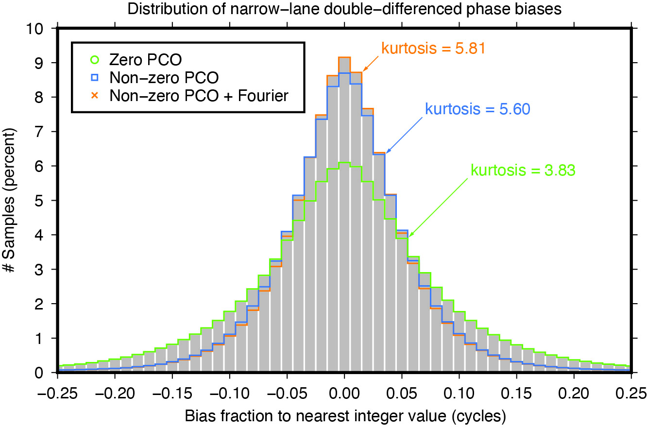
Integer ambiguity resolution — that is, resolving the unknown cycle ambiguities of double-differenced carrier-phase data to integer values — is considered indispensable to GNSS satellite POD and commonly results in a factor of two improvement in orbit precision. Of particular importance is the narrow-lane ambiguity that results from combining the carrier-phase measurements from a pair of GNSS frequencies. One of the intermediate steps in the ambiguity resolution algorithm is the fixing of the double-differenced narrow-lane ambiguities to integer values. For reliable fixing, the fractional part of the difference between the integer and decimal (float) values should be as close as possible to zero and follow a symmetrical distribution. The “tailedness” of the distribution curve may be characterized by its kurtosis — the larger the kurtosis, the fewer values are in the tails of the distribution and the more peaked is the distribution. In other words, the larger the kurtosis, the closer the “fractionals” cluster around zero, the more ambiguities can be resolved with higher confidence, and the more accurate the resolved solution. Moreover, as satellite orbit and antenna phase center errors do not cancel out completely through double-differencing, the narrow-lane kurtosis may also be considered as an indicator for the accuracy of the satellite force and phase center models that were used. The results in Figure 9 show that the non-zero horizontal PCOs bring a major improvement and that the Fourier force model does give some additional benefit.
Figure 9: Impact of horizontal antenna PCOs and Fourier force model on fractional part of double-differenced narrow-lane ambiguities.
CONCLUSIONS
Adding a new GNSS satellite type to high-precision multi-GNSS solutions requires detailed knowledge and understanding of the satellite type. Key issues are the transmit antenna phase center parameters, the satellite’s attitude, and the radiation pressure forces acting on its surfaces.
In this article, improved antenna phase center, attitude, and radiation pressure models for the current series of GPS Block III spacecraft have been developed using multiple years of in-flight orbit and tracking data. A number of internal metrics such as post-fit carrier-phase residuals, day-boundary orbit differences (overlaps), empirical acceleration parameters, and carrier phase ambiguity statistics have been used to gauge the models’ performances. Overall, the results underscore the importance of the models for GPS III orbit determination. This applies primarily to the radiation force and the antenna phase center model, or more precisely, the horizontal (X and Y) offsets of the phase center model whose existence has been neglected for years in the analysis of GPS III data.
Comparison of the overlap statistics suggest that orbits generated based upon updated (non-zero) phase center corrections and ESA/ESOC’s new (Fourier-based) radiation pressure model in the background are better by almost a factor of two. The average overlap RMS errors calculated across all current Block III SVs and for each orbital component (radial, along track and across track) dropped from 21 , 28 and 35 millimeters down to 14, 21 and 16 millimeters, respectively.
More relevant when it comes to processing GPS data recorded on board low-flying satellites such as Sentinel-6 Michael Freilich or Jason-3, is the extension of the current IGS Block III antenna PCV model beyond a 14-degree boresight angle. After applying the extended PCV corrections, we reduced Block III carrier-phase residuals by 20% with no or few systematic signatures remaining, unlike the residuals produced with the current IGS antenna model. The IGS is strongly encouraged to adopt the Block III PCV extension into their antenna model to continue to support GPS-based POD of low-Earth-orbiting satellites.
For further details on ESA/ESOC’s solar radiation pressure modeling approach, see our paper “GPS III Radiation Force Modeling” presented at the IGS 2022 Virtual Workshop: click here.
FLORIAN DILSSNER is a satellite navigation engineer in the Navigation Support Office at the European Space Operations Centre (ESOC) of the European Space Agency (ESA), Darmstadt, Germany. He earned his Dipl.-Ing. and Dr.- Ing. degrees in geodesy from the University of Hannover, Germany.
TIM SPRINGER has been working for the Navigation Support Office at ESA/ESOC since 2004. He received his Ph.D. in physics from the Astronomical Institute of the University of Bern in 1999.
FRANCESCO GINI is a satellite navigation engineer in the Navigation Support Office at ESA/ESOC. He received his Ph.D. in astronautics and space sciences from the Centro di Ateneo di Studi e Attività Spaziali at the University of Padova in 2014.
ERIK SCHÖNEMANN is a satellite navigation engineer in the Navigation Support Office at ESA/ESOC. He earned his Dipl.-Ing. and Dr.- Ing. degrees in geodesy from the University of Darmstadt, Germany.
WERNER ENDERLE is head of the Navigation Support Office at ESA/ESOC. He holds a doctoral degree in aerospace engineering from the Technical University of Berlin, Germany.
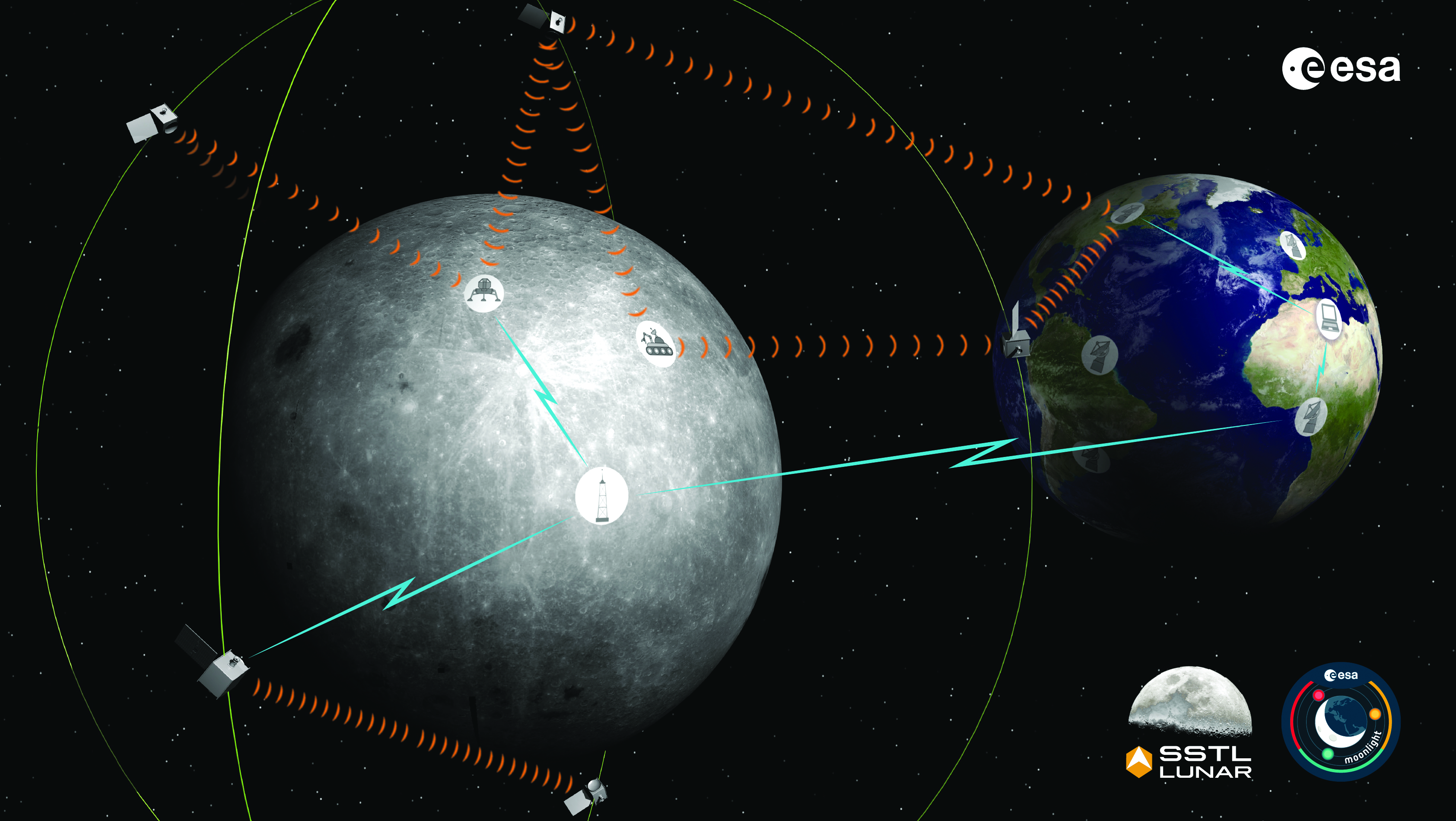
The Moonlight initiative will provide sustainable lunar data-relay services for communication and navigation around the Moon. (ESA Moonlight Study conceptual drawing.) (Image: SSTL/Airbus/ESA)
GNSS researchers presented hundreds of papers at the 2022 Institute of Navigation (ION) GNSS+ conference, which took place Sept. 19–23 in Denver, Colorado, and virtually. The following five papers focused on lunar and space applications. The papers are available now.
MTO Navigation Using Lunar Signals
The moon transfer orbit (MTO) is becoming increasingly important as several national space agencies are planning moon exploration soon, with projects such as NASA’s Artemis. In previous research, the GPS navigation accuracy on the MTO reached 200 m at the moon altitude by using GPS signals emitted from the far side of Earth. As accuracy on a low-Earth orbit (LEO) using GPS is a few meters, 200 m accuracy is not accurate enough to support lunar exploration. The deterioration of accuracy is due to the poor geometry of the GPS satellites that became visible from the MTO.
The authors want to achieve an accuracy of less than 100 m in MTO by using other navigation sources, including the lunar navigation satellite system (LNSS) to be deployed in the moon’s orbit. The LNSS signals will come from the far side of the moon, similar to the signals of GPS satellites coming from the opposite side of Earth. Its satellites will be pointed towards the moon to provide positioning, navigation and timing services on the moon surface, especially at the lunar South Pole region
The researchers have been conducting the simulation evaluation for the MTO navigation accuracy using signals coming from the moon and assume that these signals will be emitted from beacons on the moon surface or the LNSS.
Murata, Masaya; Kogure, Satoshi; “Moon Transfer Orbit Navigation Using Signals Coming from the Moon.”
Designing the Smallsat-Based LNCSS
There is growing interest in the use of a smallsat platform for the future lunar navigation and communication satellite system (LNCSS); however, many design considerations are not finalized for the smallsat-based LNCSS, such as choice of the satellite clock, satellite orbital parameters and the constellation size.
Using the Systems Tool Kit simulation software, the authors examined various LNCSS constellation case studies based in elliptical lunar frozen orbit and with a low-grade chip-scale atomic clock.
They evaluated case studies of navigation design considerations including position and timing accuracy, lunar user equivalent ranging error, and dilution of precision. As for case studies of communications design considerations, the authors examined daily data volume, availability and data rate. Finally, they examined smallsat factors including the cost, size, weight and power of the satellite payload.
The paper includes trade-off analysis in satisfying the preliminary design criteria outlined by international space agencies and commercial space companies.
Bhamidipati, Sriramya; Mina, Tara; Sanchez, Alana; Gao, Grace; “A Lunar Navigation and Communication Satellite System with Earth-GPS Time Transfer: Design and Performance Considerations.”
Developing an SDR for Space
A geostationary satellite (GEO) equipped with the satellite-based augmentation system (SBAS) function has a transmitter for GNSS correction signals at the L1 and L5 bands. This transmitter could interfere with the GNSS space service volume (SSV) receiver in the same satellite, so L1 and L5 signals cannot be used for the GEO SBAS satellite. However, the use of GPS L2C signals can be an alternative.
The authors of this paper present the development of a GPS L2C signal generator for the SSV in GEO simulation. They present the simulation process for GEO satellites and the structure of the GPS L2C signal generator.
In this study, a verification through the receiver test with a GNSS software-defined receiver is included to show the possibility of the designed signal simulator. The validation is performed by analyzing the programmable system device, the results of the acquisition, code/carrier tracking, and the C/N0 estimation.
Lee, Hak-beom; Choi, ByeongHyun; Song, Young-Jin; Won, Jong-Hoon; Kwon, Ki-Ho; “Development of GPS L2C Signal Generator for SSV in Geostationary Orbit Simulation.”
Differential Positioning on the Moon
This paper introduces a new concept of delivering the pseudorange correction calculated at a reference station on the lunar surface, as a part of the lunar navigation satellite system (LNSS) navigation message. The concept enables LNSS users to apply differential positioning using pseudorange correction without adding new hardware to their receivers.
The authors propose the differential positioning technique to reduce the signal-in-space range error of LNSS satellites and the coordinate transformation errors from Earth-centered fixed frame to lunar reference frame — the dominant errors in satellite positioning by LNSS.
The proposed reference station is equipped with instruments to externally estimate its own position relative to the lunar reference frame. The user on the lunar surface would then perform differential positioning using the station coordinate and pseudorange correction obtained at the reference station.
In this study, the simulation results using eight elliptical lunar frozen orbit satellites show that the real-mean-squared values for both horizontal and vertical positioning errors with differential correction are reduced to 1/10 of those without differential correction, even at 10 degrees latitude from the reference station at the lunar South Pole.
Akiyama, Kyohei; Murata, Masaya; Kogure, Satoshi; “Differential Positioning Performance on Lunar South Pole Region Using Lunar Navigation Satellite System.”
GEO Precise Orbit Determination
Using GPS in satellites in geostationary (GEO) orbits provides advantages by improving position, velocity and timing data, reducing operating costs and providing autonomous orbit control for station keeping. This paper presents the result of the onboard data evaluation and precise orbit determination of an optical data-relay satellite (ODRS) using GPS L1 C/A code and carrier-phase observations for 74 days.
As a result of precise orbit determination, the authors found that both code- and carrier-phase observations are affected by the ionospheric delay when signals pass through the plasmasphere located above the ionosphere.
Several methods were implemented during this research to reduce the effect of the plasmasphere, including setting a higher cut-off altitude, applying correction sequences generated from orbit determination residuals, and applying a new observation noise model depending on the GPS off-nadir angle. Results show that the correction sequences and the new noise model improve the internal orbit consistency. The authors also found that the orbit bias in radial direction due to negatively biased carrier-phase observations is mitigated from –51 cm to –17 cm by setting a higher cut-off altitude and applying correction sequences.
Matsumoto, Takehiro; Sakamoto, Takushi; Yoshikawa, Kazuhiro; Kasho, Sachiyo; Nakajima, Ayano; Nakamura, Shinichi; “GEO Precise Orbit Determination Using Onboard GPS Carrier Phase Observations of Optical Data Relay Satellite.”


