A roundup of recent products in the GNSS and inertial positioning industry from the December 2024 issue of GPS World magazine.
Mapping
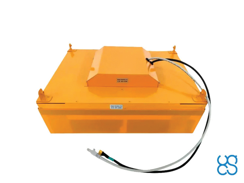
Photo: SPH Engineering
GPR System For terrestrial and airborne applications
The Zond Aero 500 NG is a versatile ground penetrating radar (GPR) system designed for both terrestrial and drone-mounted surveys, suitable for applications such as utility scanning, sinkhole detection, glaciology and geological studies. It operates in dual mode, allowing for ground-based and airborne surveys, enhancing data collection flexibility. Key specifications include a center frequency of 500 MHz, an operating bandwidth of 200 MHz – 900 MHz, a sampling rate of 25,600 samples per second and a scan rate of 50 scans per second, with depth penetration up to 4 meters in average soil conditions. The system features advanced electronics for real-time data collection, which can significantly improve the signal-to-noise ratio. It is compatible with DJI Matrice 300/350 UAVs for airborne applications.
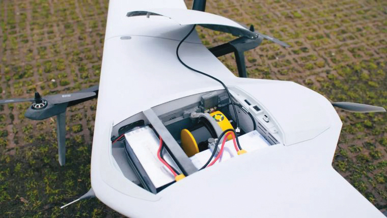
Streamlined Lidar Mapping YellowScan’s Surveyor Ultra integrated with DeltaQuad Evo
Integrating YellowScan’s Surveyor Ultra with the DeltaQuad Evo platform allows users to collect high-precision, high-density data across 1,200 hectares in a single flight while simultaneously capturing lidar and RGB data.
DeltaQuad Evo’s long-range flight capabilities and efficient vertical take-off and landing (VTOL) design, paired with the Surveyor Ultra’s lidar technology, allow users to streamline their workflows to reduce time spent in the air and on post-processing tasks, making it particularly beneficial for large infrastructure projects, forestry analysis and environmental monitoring. The system can be used for surveying, construction, forestry and environmental research.
Airborne Mapping System With a ‘cross-fire’ scan pattern
The VQ-1560 III-S is a dual-channel laser scanning system designed for airborne mapping applications. Its “cross-fire” scan pattern allows for simultaneous forward and backward viewing at the edges of the swath, along with a nadir view in the center. This configuration optimizes point distribution for effective target sampling. With pulse repetition rates reaching up to 4.4 MHz, the VQ-1560 III-S can operate at altitudes of up to 1,600 m above ground level (AGL). At a lower pulse repetition rate of 560 kHz, it can function at altitudes as high as 3,900 m AGL.
The system features inertial measurement unit (IMU) and GNSS integration, with the option to include one or two high-resolution RGB/NIR cameras. It is ideal for professionals in fields such as urban planning, forestry and environmental monitoring.
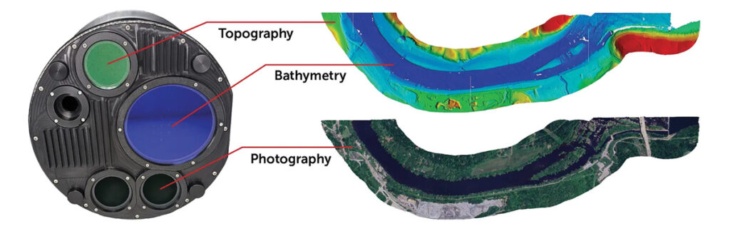
This bathymetric lidar system is designed for coastal and inland water mapping. It combines high-resolution topographic and bathymetric capabilities, allowing for seamless data collection across land and sea. It can be used for coastal zone management, environmental monitoring, infrastructure planning and more.
Fathom delivers data quickly by leveraging real-time quality control with Onboard and scalable processing with a CARIS workflow. It also includes a built-in topographic lidar and a multispectral camera for coastal surveys at a coverage of 50 km2/hour.
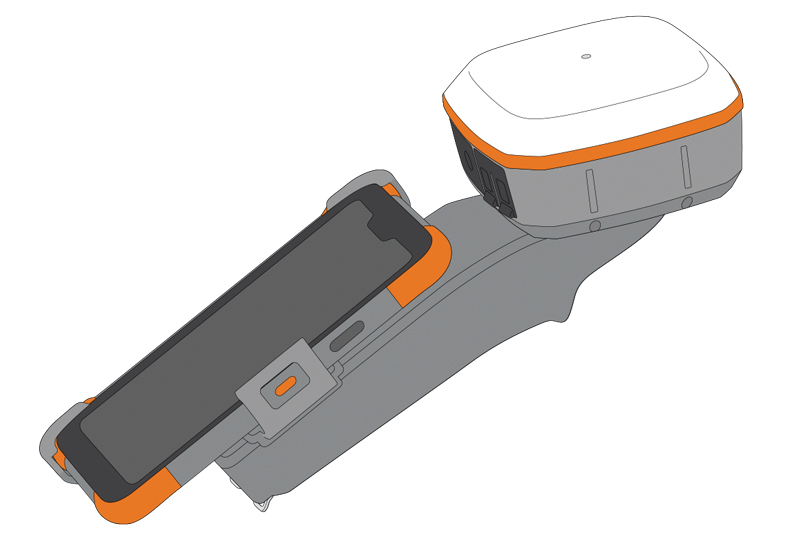
The Geode Grip is a mounting accessory featuring a specialized bracket. It allows users to securely attach smartphones directly to Juniper’s Geode GNSS receivers, offering an integrated and streamlined data collection solution.
The Geode Grip is a tool designed for professionals in surveying, mapping and geographic information systems (GIS) to enhance mobile data collection. It replaces the traditional survey pole with a handheld setup that aims to improve ergonomics. It is ideal for field projects that require precise location data and mobile data collection, such as environmental research, land surveying, agriculture and infrastructure engineering.
New Product Bundle For high-accuracy GNSS applications
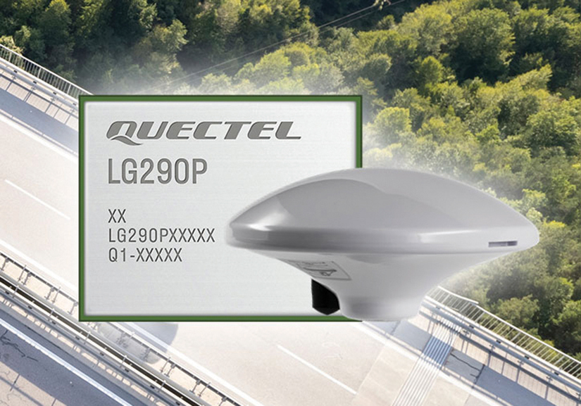
Quectel Wireless Solutions has unveiled a new product bundle designed to facilitate the development of high-accuracy GNSS applications. The bundle includes the LG290P GNSS module, which is a quad-band, multi-constellation device capable of receiving signals from various satellite systems, including GPS, GLONASS, Galileo, BDS, QZSS and NavIC. The LG290P is engineered for high precision and supports RTK positioning, allowing for centimeter-level accuracy even in challenging environments. It can be used in diverse applications, such as autonomous vehicles, precision agriculture and surveying.
In addition to the LG290P module, the bundle includes options for either the YEGN103W8A geodetic antenna or the YEGD006U1A patch antenna. Both antennas are designed to operate within the same frequency bands as the GNSS module and are compliant with environmental regulations such as RoHS. This pre-integrated solution simplifies developers’ procurement and integration process by providing a one-stop solution that combines antennas with GNSS modules and RTK correction services.
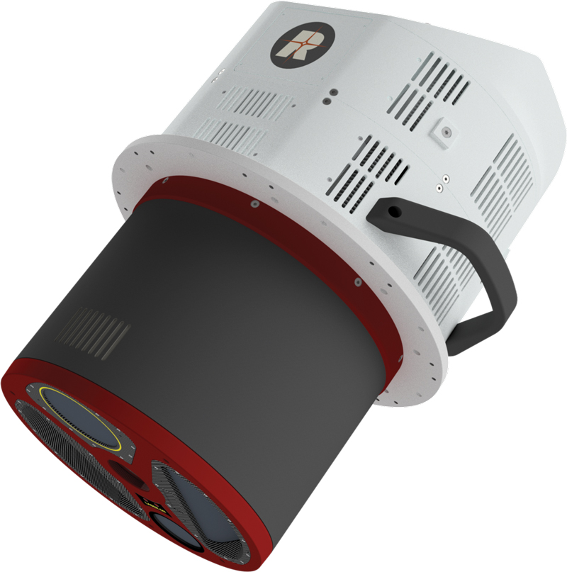
Lidar Camera Payload For surveying and mapping applications
The RESEPI Ultra LITE is a lightweight payload combining lidar and camera technology for advanced surveying and mapping applications. The system integrates the XT-32 lidar scanner to offer users advanced data accuracy and point density across various operational modes.
It has a compact design with a 5MP colorization camera, making it ideal for small unmanned aerial systems (SUAS) with strict volume constraints. It can be used for aerial and ground-based applications, including utility mapping, construction volumetrics, precision agriculture, forestry, site surveying and mining. Designed for seamless integration, the system is compatible with a wide range of platforms such as Freefly, WISPR, DJI, Sony and mobile setups. Inertial Labs’ proprietary SnapFit adapters ensure quick and secure mounting to enhance the system’s adaptability.
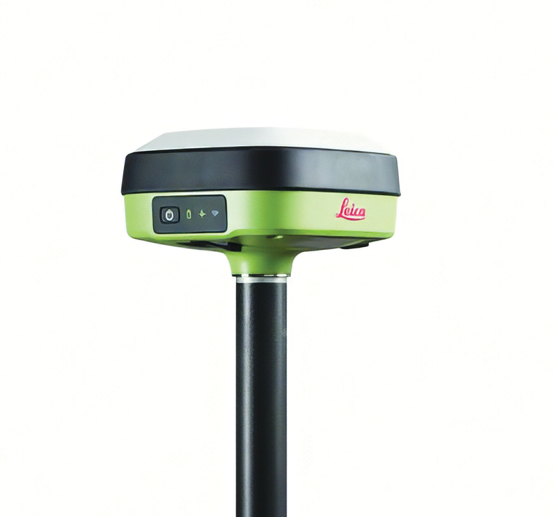
The Leica GS05 is a compact and lightweight GNSS smart antenna designed for surveying tasks, featuring calibration-free tilt compensation. This robust device allows for accurate measurements even when the survey pole is tilted up to 30°, enhancing data collection in challenging environments. Its integration with Leica Geosystems’ portfolio, including Leica Captivate software and total stations, seeks to maximize efficiency. The GS05 can function as both a base and an RTK rover, supporting single base stations and RTK networks such as Leica SmartNet.
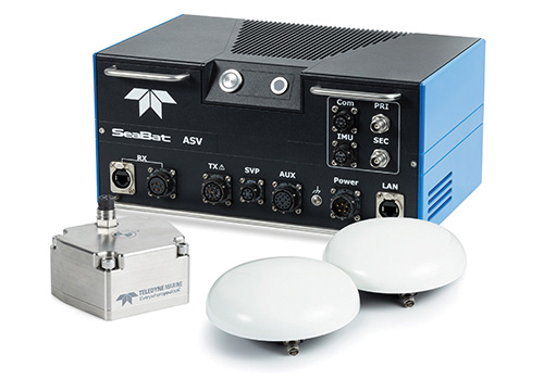
Intrepid is a GNSS/INS system integrated with the SeaBat T20-ASV processor and includes a compact IMU and two GNSS antennas, ensuring reliable and precise positioning.
It can automatically stream data to third-party software. This eliminates the need for manual sensor interfacing and reduces downtime. The Intrepid GNSS/INS benefits users in marine surveying applications by providing the precise navigation necessary for operational efficiency. Its intuitive design allows for simple configuration.
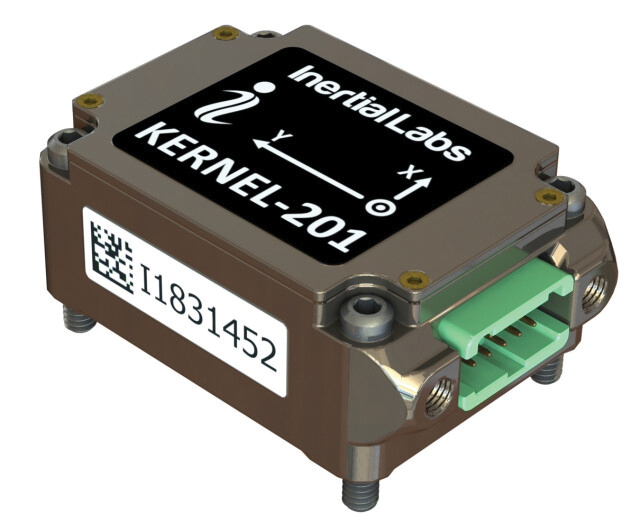
Miniature MEMS Sensor-Based IMU Can withstand high shock and vibrations
The KERNEL-201 features three-axis MEMS accelerometers and gyroscopes that offer ultra-low noise, high bandwidth and minimal latency. These characteristics make it ideal for applications such as pointing, stabilization and navigation in systems where performance and size are critical. Its volume of 0.38 cubic inches offers a high dynamic range.
Fully calibrated and temperature-compensated, the unit offers consistent, precise measurements even in challenging environments. It features an in-run bias stability of up to 0.7 deg/hr for gyroscopes and 0.005 mg for accelerometers, along with a low angular random walk (ARW) of 0.065°/√hr and velocity random walk (VRW) of 0.015 m/sec/√hr.
The unit is designed to withstand high shock and vibration while maintaining peak performance, making it suitable for a wide range of challenging applications. The KERNEL-201 can be integrated into various high-level systems, such as motion reference units (MRUs), GPS-aided inertial navigation systems (INS) and attitude and heading reference systems (AHRS). It offers continuous built-in testing (BIT), customizable communication protocols and flexible power options.
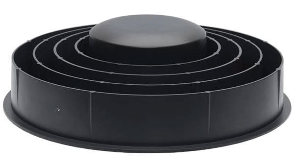
Smart Choke Antenna Offers comprehensive GNSS signal reception
The VCS6000XF full band smart choke antenna is engineered for CORS applications. It combines Tallysman Verachoke antenna elements with Septentrio’s Mosaic X5 full-band receiver to offer an integrated solution for OEM CORS systems.
The VCS6000XF offers comprehensive GNSS signal reception, including GPS/QZSS L1/L2/L5, GLONASS G1/G2/G3, Galileo E1/E5a/E5b/E6/E5 AltBoc, BeiDou B1/B2/B2a/B3, NavIC L5, SBAS and L-Band correction services.
The antenna features a 0.5 mm phase center variation and utilizes Calian’s eXtended filtering for near-band signal interference mitigation. The integrated Septentrio Mosaic X5 receiver provides capabilities such as anti-jamming, anti-spoofing, scintillation mitigation and receiver integrity by combining the antenna and receiver in the choke ring antenna.
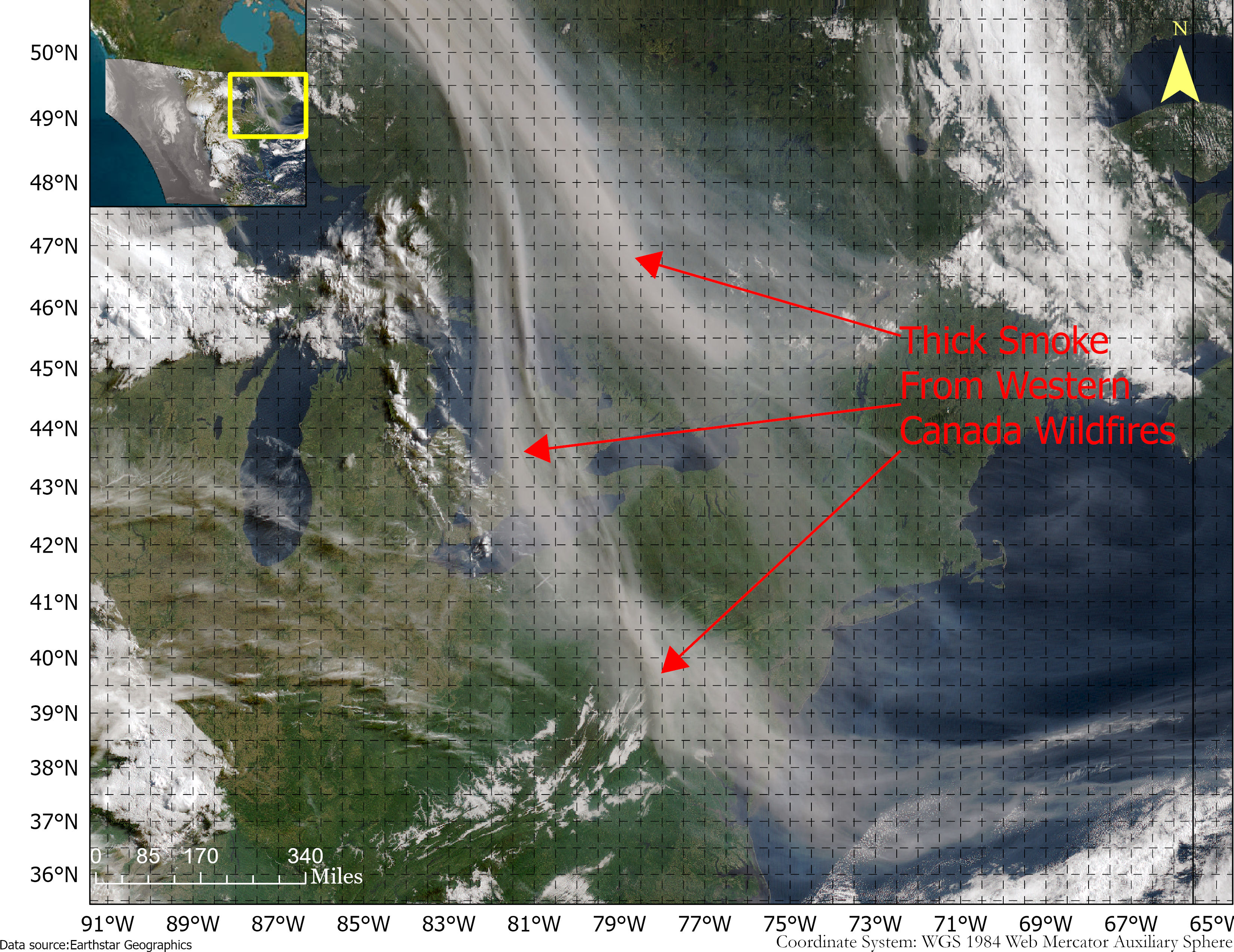
Smoke from the Canadian wildfires continues to pollute the air across the United States, mainly affecting cities in the northeast, including Pittsburgh, Chicago, Cleveland, Detroit and Buffalo.
According to the New York Times, in early June, the level of particulate matter in the air from smoke became so unhealthy that many U.S. cities set records. Visibility decreased in many cities as well, with the smoke creating an orange haze.
Most of the smoke can be attributed to several fires burning across Canada. Many of these fires were caused by lightning; however, with above-average temperatures and dry conditions, wildfires have been breaking out since May.
A storm system off the coast of Nova Scotia forced smoke from the fires southeast into the United States. (Image: NOAA)
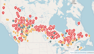
Based on data from the Canadian Interagency Forest Fire Centre, there are 480 active fires in Canada: 252 are out of control, 77 are being held in place, and 151 are under control.
The fires are mapped in the image below.
The red dots represent the out-of-control fires, the green dots are fires being held in place, and the yellow dots are fires that are under control. (Image: Screenshot of CIFFC wildfire map)
Understanding air quality importance
The Air Quality Index (AQI) measures the density of five pollutants: ground-level ozone, particulates, carbon monoxide, nitrogen dioxide, and sulfur dioxide. It was originally established by the Environmental Protection Agency to communicate the cleanliness of the air Americans are breathing every day.
The index runs from zero to 500 — the higher the number the more polluted the air is.
Effects of air pollution can range from mild symptoms, such as eye and throat irritation, to serious ones such as heart and respiratory issues. Pollution can cause inflammation of the lung tissue and increase the vulnerability to infections.
During wildfires, fine particles in the soot, ash and dust can fill the air.
The AQI identifies the concentration of particles smaller in diameter than 2.5 μM. When these particles are inhaled, the tiny specks can increase the risk of heart attacks, cancer, and respiratory infections — especially in children and older adults.
Below is an updated map of air quality from the U.S. AQI as of June 28.
The colors on the map range from yellow — which is unhealthy air quality — to purple, meaning the air quality is hazardous. (Image: AirNow.gov)
Image: Johan Holmdahl/iStock/Getty Images Plus/Getty Images
The Nippon Foundation—General Bathymetric Chart of the Oceans (GEBCO) Seabed 2030 Project has partnered with NORBIT Oceans, a provider of underwater imaging and mapping technology. The organizations aim to advance the field of ocean science and obtain a complete map of the entire ocean floor.
Under the partnership, NORBIT Oceans will strengthen the capabilities of the Seabed 2030 Project and its network by providing solutions involving bathymetric survey data sets, research voyages, and general survey activities.
A collaborative project between the Nippon Foundation and GEBCO, the Seabed 2030 Project aims to inspire the complete mapping of the world’s oceans by 2030, and to compile all the data into the freely available GEBCO Ocean Map. GEBCO is a joint program of the International Hydrographic Organization (IHO) and the Intergovernmental Oceanographic Commission (IOC) and is the only organization with a mandate to map the entire ocean floor.
With a focus on providing technology solutions to global maritime markets, NORBIT Oceans is one of three segments within the global technology company NORBIT ASA, based in Norway. NORBIT Oceans offers solutions for seafloor mapping, environmental monitoring, tailored products for the aquaculture and security markets, as well as customized cables.
All data collected and shared with the Seabed 2030 Project is included in the free and publicly available GEBCO global grid.
The Linux Foundation has launched the Overture Maps Foundation, interoperable open map data for developers who build map services or use geospatial data and to strengthen mapping services globally. Overture expects to release its first datasets in the first half of this year.
Overture aims to deliver services including collaborative map building by incorporating data from Overture members, civic organizations, and open data sources, creating a global entity reference system, quality assurance processes to detect map errors and ensure map data can be used in production systems, and a structured data schema to create an ecosystem of map data. Additionally, map data is open and extensible to users under an open data license.
Founded by Amazon, Meta, Microsoft and TomTom to help developers source and curate up to date map data, Overture will integrate with existing open map data from projects such as OpenStreetMap and city planning departments, as well as with new map data contributed by members, to create a living digital record of the physical world using artificial intelligence and machine leaning techniques.
The initial release of datasets will include basic layers including buildings, roads and administrative information with plans to improve coverage, resolution and accuracy of existing data over time. It also will introduce new layers including places, routing and 3D building data.
Trimble Maps enables a shipping company to offer one-hour delivery windows. (Photo: Trimble)
To reduce its emissions, DPD Deutschland — a franchise of DPDgroup, one of the largest international parcel carriers in Europe — has asked Trimble Maps to help optimize its operations. DPD Deutschland’s parcel supply chain covers 80 franchise depots, 9,500 employees and more than 13,000 drivers, delivering about 2 million packages to businesses and consumers per day via a mixed fleet of vehicles, including electric ones.
DPDgroup has a vision to become the international standard in sustainable delivery by 2030. Per parcel, it has reduced its CO2 emissions by 18.8% since 2013 and is on track to reach a 30% reduction by 2030, according to Trimble.
One of DPD’s most popular service offerings, called Predict, allows parcel recipients to track the progress of their deliveries in real time, with an estimated one-hour delivery window and updated notifications along the way. Since 2014, Trimble Maps’ portfolio has helped calculate this one-hour delivery window and provided turn-by-turn navigation to DPD drivers, resulting in less overall travel time, more successful first-time deliveries and reduced emissions.
DPD was the first, and still is the only, parcel carrier in Germany that provides recipients with an estimated one-hour delivery window, the company says, calculating it for every parcel. The service is made possible in part by the integration of Trimble Maps’ route optimization and mapping web services platform, known internally as DPD Maps. Recipients can reschedule deliveries as needed for future days and times, or perhaps to a convenient drop-off location. This reduces emissions created by multiple return trips.
DPD Maps calculates an optimized route for drivers, who are then able to manually sort the stops and change the route to best fit their preferences. Once routes are locked in, Trimble’s commercial navigation application, CoPilot, provides drivers with real-time directions. Once a driver’s route is complete for the day, DPD can compare the actual route taken with the optimized route DPD Maps calculated in an easy-to-understand view that can be analyzed by the driver and the depot.
DPD Maps allows the company to visualize, share and discuss results with different stakeholders within the organization. The solution also allows drivers to plan out their day as they see fit, while giving the back office access.
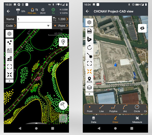
CHC Navigation has released LandStar8, a field surveying and mapping application for Android devices. LandStar8 is designed to be flexible and user-friendly for surveying and mapping tasks.
LandStar8 is versatile, modular and customizable for topographic tasks such as surveying, stake out, cadastral, mapping and geographic information systems (GIS). Building on the legacy of LandStar7, the new LandStar8 provides features such as a refined user interface, streamlined workflows, faster operation, and integrated cloud services.
“With LandStar8, we want to provide our users with unprecedented field experience,” said Rachel Wang, product manager of CHC Navigation’s Surveying and Engineering Division. “LandStar8’s modular design allows users to customize the interface according to their usage habits, making it easier and more efficient for field crews to work.”
Cloud connectivity is built in, for backup, data storage or remote technical support.
LandStar 8 has a simple and intuitive layout with large map windows and sharp graphics. Users can hide features they rarely use and display only those they need.
On LandStar8, users can copy coordinate settings, control and staking points from another handheld controller by scanning a QR code. Projects can be edited and sorted by history and attributes. Custom coordinate systems, geoid models and coding libraries can be updated at any time by using resource packages. LandStar8 also features a terrain calibration wizard designed specifically for non-expert users.
A proprietary MetaCAD graphics engine opens DWG and DXF base maps faster and with smoother rendering. DXF files up to 200 MB can be opened in less than 10 seconds. LandStar8 also supports opening external reference files, automatically recognizes CAD length units, and allows editing of CAD base maps directly in the field.
LandStar8 is designed around a comprehensive cloud-based architecture that supports project backup, collaborative work and data storage. Its remote support capabilities help the office helpdesk resolve user problems and provide personalized technical assistance. A “share code” feature allows users to transfer project data between desktop computers and field controllers or among field controllers quickly to further boost work efficiency.
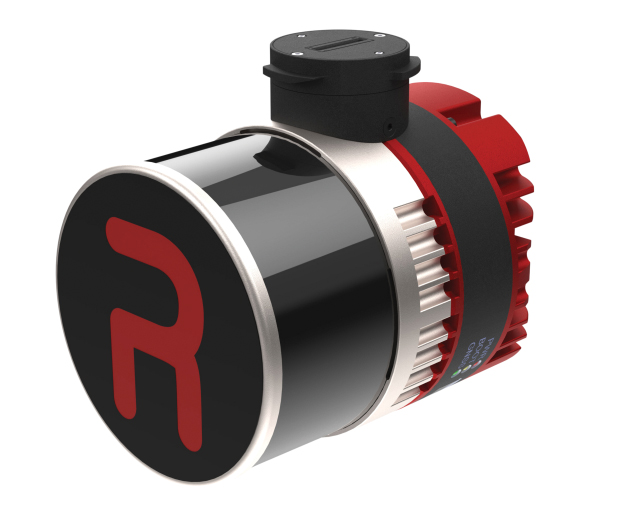
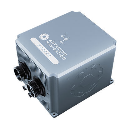
The D70 is the latest release in the Boreas digital FOG (DFOG) series, offering a new performance grade with superior accuracy, exceptional stability and reliability. The technology is suited to surveying, mapping and navigation across subsea, marine, land and air applications.
“We are thrilled to expand the Boreas series with the D70. It’s a system that will provide additional flexibility in the Boreas family, making ultra-high accuracy inertial navigation far more affordable than with previous FOG INS systems,” said Xavier Orr, CEO and co-founder of Advanced Navigation. “This patented technology opens the possibility for adopting FOG INS systems across a much broader range of vehicular applications, particularly autonomous vehicles and aircraft where weight and size are at a premium.”
Boreas D70 combines closed-loop DFOG and accelerometer technologies with a dual-antenna real-time kinematic (RTK) GNSS receiver. These are coupled with Advanced Navigation’s artificial-intelligence-based fusion algorithm to deliver accurate and precise navigation.
The system features ultra-fast gyrocompassing, acquiring and maintaining an accurate heading under demanding conditions. While the D70 does contain a GNSS receiver, it is not required for gyrocompass operation.
Based on the company’s DFOG technology, the D70 delivers a 40% reduction in size, weight, power and cost (SWaP-C) when compared to systems of similar performance.
0.01° roll and pitch
0.1° secant latitude heading (gyrocompass)
0.01°/hour bias instability
10 mm position accuracy
The Boreas Series
The Boreas DFOG series features ultra-fast gyrocompassing and can acquire heading, either stationary or dynamically, in less than two minutes. The gyrocompassing allows the system to determine a highly accurate heading without any reliance on magnetic heading or GNSS.
The technology stems from Advanced Navigation’s artificial intelligence sensor-fusion algorithm allowing the system to extract significantly more information from the data. It is designed for control applications, with a high level of health monitoring and instability prevention to ensure stable and reliable data.
Advanced Navigation designed Boreas from the ground up for reliability and availability. The hardware and software are designed and tested to international safety standards and have been environmentally tested to MIL-STD-810. The system achieves a mean time between failure (MTBF) of more than 70,000 hours.
Additional features of the Boreas D70 include Ethernet, CAN and NMEA protocols, as well as disciplined timing via a PTP server and 1 PPS. An embedded web interface provides full access to all of the device’s internal functions and data. Internal storage allows for up to 1 year of data logging.
About DFOG Technology
DFOG is patented technology, which has been developed over 25 years involving two research institutions. DFOG was created to meet the demand for smaller and more cost-effective FOGs, while increasing reliability and accuracy.
The first generation of FOG, made available in 1976, used analog signals and analog-signal processing. The second generation was developed in 1994 and is still used to this day. It improved upon the first generation with a hybrid approach using an analog signal in the coil with digital signal processing.
In 2021, FOG evolved into DFOG. This third generation of FOG sets itself apart by being completely digital, providing higher performance and reliability while enabling a 40% reduction in SWaP-C.
To achieve this, three different yet complementary technologies have been developed to improve the capabilities of FOG.
Digital Modulation Techniques. DFOG uses a specially developed digital modulation technique passing spread spectrum signals through the coil. The new digital modulation technique introduced in DFOG technology allows in-run variable errors in the coil to be measured and removed from the measurements. This makes DFOG significantly more stable and reliable than traditional FOGs. It also allows a smaller FOG with less coil length to achieve the accuracy of one with a longer coil.
Revolutionary Optical Chip. By integrating five sensitive components into a single chip and removing all the fiber splices, the size, weight and power are reduced considerably while significantly improving reliability and performance.
Specially Designed Optical Coil. DFOG employs a specially designed closed-loop optical coil, developed to take full advantage of the digital modulation techniques. The design allows for optimum sensing of in-run variable coil errors using the new digital modulation technique. It also provides a very high level of protection for the optical components from shock and vibration.
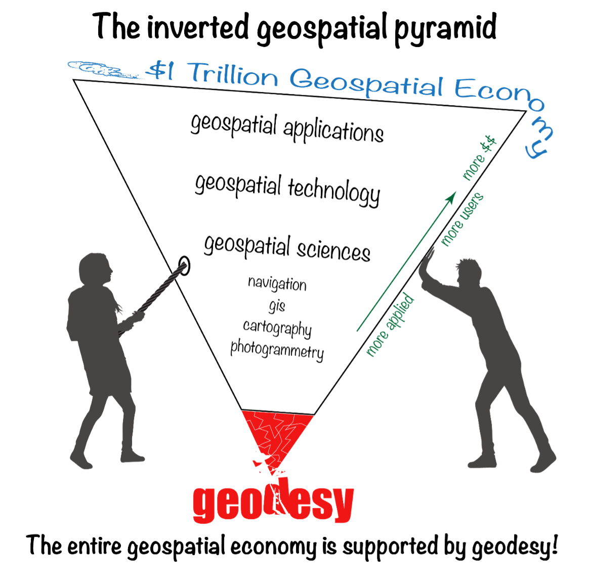
Last year I was privileged to be part of a Blue-Ribbon Review Panel for an American Society of Civil Engineers (ASCE) surveying publication. The book is Surveying and Geomatics Engineering: Principles, Technologies, and Applications. I recently received my copy of the published book in the mail and decided to highlight some sections. While preparing this column, the chapters reminded me of how geodesy has expanded into so many different disciplines.
I first mentioned this in my July 2020 article for the “First Fix” column of GPS World, where I stated that the shortage of American trained geodesists poses a significant economic risk for the United States. In that column, I mentioned how geodetic science and technology now underpin many sciences, large areas of engineering (such as driverless vehicles and drones), navigation, precision agriculture, smart cities and location-based services. That is why I believe understanding geodesy is more critical today than ever. In January 2022, Mike Bevis, collaborating with others, prepared a white paper titled “The Geodesy Crisis,” documenting the concern about the lack of trained geodesists in the United States.
Image: Dana Caccamise II
“The inverted geospatial pyramid” graphic depicts how the entire $1 trillion geospatial economy is supported and dependent on geodesy, and how it’s close to collapsing without an increase of support for geodesy. A lack of geodetic expertise in the United States presents a significant challenge, with future impacts on positioning, navigation, mapping and dependent geospatial technologies.
In my opinion, without investment in geodesy, the United States will not have the available skills and knowledge to develop new geodetic technologies and improve models to address challenges to society, such as
how the Earth’s surface is changing as sea level rises and the Earth’s glaciers and ice sheets change on timescales of months
how the tectonic plates are deforming and what physical processes control earthquakes, and
the ability to monitor the temporal changes in Earth’s water reservoirs by measuring changes in Earth’s gravitational field as it responds to the moving water mass and the deformation of the solid Earth caused by moving water.
These challenges need a well-maintained, stable terrestrial reference frame (TRF) with sub-1 mm/year vertical accuracy. Errors in TRF heights can propagate systematically into estimates of atmospheric water vapor, sea level, satellite orbits and other parameters. An accurate TRF can lead to important observations and discoveries because it enables revelations from coherent global motions. (My previous column described the latest International Reference Frame of 2020 [ITRF2020].)
Geodesy has been a significant part of my life for 50 years. I’ve seen a lot, and unless we address the Geodesy Crisis, the innovations in geodetic science of the past will not continue in the future. At least not in the United States.
The Geodesy Crisis paper was mentioned in the Fall 2022 ION Quarterly Newsletter by Everett Hinkley (see the box below). Hinkley noted, “The geospatial community relies on geodesists, though few in the community are fully aware of this connection nor understand the importance of geodesy to their work.” I encourage everyone to download the white paper and the ION Quarterly Newsletter to understand the importance of the need for more trained geodesists.
Excerpt from Everett Hinkley’s Article
“In January 2022, a white paper entitled America’s loss of capacity and international competitiveness in geodesy, the economic and military implications, and some modes of corrective action was released (Bevis et al.). This collaborative paper paints an alarming picture of the dwindling pool of trained geodesists within the United States. The report highlights America’s loss of capacity and international competitiveness in geodesy and states: ‘The U.S. is on the verge of being permanently eclipsed in geodesy and the downstream geospatial technologies. This decline in capability threatens our national security and poses major risks to an economy strongly tied to the geospatial revolution, on Earth and, eventually, in space.’ Though the word crisis correctly describes the dire predicament well, it didn’t occur overnight. Due to several converging trends, the geodesy crisis has been decades in the making. A national lack of geodetic expertise presents a significant challenge with downstream impacts on positioning, navigation, mapping, and dependent geospatial technologies. The Department of Defense, intelligence community, and federal civil agencies’ mapping entities rely on accurate and precise maps for a broad range of purposes, and reliable maps depend on an accurate geodetic underpinning. The geospatial community relies on geodesists, though few in the community are fully aware of this connection nor understand the importance of geodesy to their work.” (Reproduced with permission from ION.)
In my “First Fix” column, I mentioned that I attended The Ohio State University (OSU) to obtain my graduate degree in Geodetic Science in 1979. Therefore, I admitted that I am a little biased — once a geodesist, always a geodesist. That said, in OSU’s geodesy heyday (1960–1990s), many Americans trained were sent there by federal agencies: National Geospatial-Intelligence Agency (NGA), NOAA/National Geodetic Survey (NGS), USGS, Army, Navy and Air Force. During the 1970s, NGS sent two employees back to school every year. These agencies needed geodesists because they were undertaking significant projects, such as the NGS projects to readjust the U.S. national horizontal (NAD83) and vertical geodetic (NAVD88) networks. I was one of the employees NGS sent to OSU to be trained to support the NAD83 and NAVD88.
Today, the environment is different. U.S. federal agencies still need geodesists to develop enhanced and refined geodetic models and tools. However, major U.S. companies, such as Google and FedEx, the automobile industry, the construction industry (automated machine guidance), precision farming companies and mining companies also need more accurate geodetic models, tools and algorithms. Therefore, these companies also need trained geodesists to perform essential research on topics that address their geodetic requirements. As indicated in “the inverted geospatial pyramid” graphic, the entire $1 trillion geospatial economy is supported by geodesy.
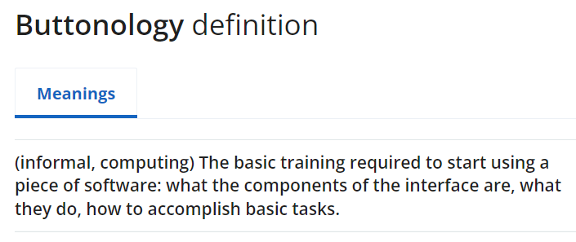
As implied in Hinkley’s article, geodesy has played a role in developing geospatial products but most users didn’t realize that it was their foundation. Since it’s been in the background, everyone assumes it will always be there. A participant at one of my workshops stated that “GPS has made geodesists out of all of us.” In my opinion, the advancements in GNSS equipment and processing software provided some users with a “false sense of knowledge or security” that they understood what was happening within the “black box.” One of my colleagues at NGS said that the new equipment and software programs were creating a field force of “buttonologists.”
These statements concerned me at the time and concern me today. With the last generation of trained geodesists either retired or getting ready to retire, we are at a critical stage of not being able to meet the geospatial needs of the future. As indicated in the white paper, there are significant challenges in rebuilding programs that support the training of geodesists.
Hinkley’s article summarized several action items that could help improve the lack of trained geodesists in the United States. I’ve provided his list in the box below. I’ve highlighted several items the surveying and mapping community can help achieve.
So how do we build and educate the next generation of geodesists?
Make the White House and Congress aware of this crisis, particularly its national security implications; seek direct support in the federal budget to correct this issue. It has become clear that, without engagement at the highest echelons of the U.S. government, averting this current crisis and its eventual outcome is unlikely.
Teach rigorous math in our public schools; follow the scholastic math approach used in many Asian and European countries.
Encourage creative thinking!
Actively market geodesy in high schools as a rewarding career for the math stars before college entry.
Build back, support and sponsor geodesy programs at select universities. This support needs to be strategic, with backing from the highest levels of the U.S. government.
Break our cultural trend of reactions to crises and seize the opportunity to be proactive and prevent the foreseen consequences of this crisis.
Encourage U.S. government support in the form of grants, professional development of staff, and research collaborations/affiliations. There are early efforts underway to bring new talent into the pipeline:
the National Geospatial-Intelligence Agency (NGA) is forming an emerging scientist consortium (ESCON) with partnerships that exist with Ohio State, UT-Austin, and other industry/academic/government partners
a pilot Ph.D. geodesy educational program with three NGA and one NGS employee is in place; the NGA expects to continue growing this program.
the NGA’s new western headquarters in St. Louis will bring 350 companies and organizations into the regional GEOINT ecosystem.
If we answer this call to action collectively, there is hope that a new cadre of U.S. geodesists can be cultivated before it’s too late to recover.
(Reproduced with permission from ION.)
With all that said about the need for more geodesists, one thing that this ASCE publication may do is make some readers realize how much they don’t know about the roots of the technology that they’re using to create geospatial products and services. This knowledge gap is not just correctly using GNSS and other geospatial technology to perform a survey, but also integrating various instruments to create an accurate mapping system, such as mobile mapping and terrestrial laser systems. My intent is not to criticize the expertise or knowledge of anyone, and I only mean to point out that in today’s use of computers and programs, many technical concepts are hidden in “black boxes.” I learned many things about some topics by reviewing this book.
The book is 556 pages and has 15 chapters. As part of my responsibilities as a Blue-Ribbon Panel member, I read every word in the book, and not many people will read the entire book. Still, I would encourage surveyors, engineers, geodesists, photogrammetrists and GIS and remote-sensing practitioners to obtain a copy of the book for reference and to understand the limitations of geospatial technology.
Now to the book’s content. I want to highlight that the forward is written by Juliana Blackwell, director of the National Geodetic Survey (NGS). She states that “A common thread running through the manual is the importance of the National Spatial Reference System (NSRS) to modern geospatial applications.”
Most of my columns highlight something relevant to the NSRS. That’s because the NSRS is the foundation layer for United States federal geospatial products, and geodesy provides the foundation for all geospatial products and services as indicated in the “The inverted geospatial pyramid” figure.
I would also like to highlight a statement by Gene Roe in the preface. He states, “Because entire books could be devoted to each of these topics, this manual only provides a summary, and it points the readers to important references where they can find more details. The manual is meant to provide a comprehensive but general overview to help support education and inform practicing engineers on the important role of the surveying engineer. It is too important for this not to occur.”
I agree with Roe’s statement that the book is important for surveying engineers. Still, I would add that this book is important to anyone working with GNSS and other geospatial data, especially geodesists, surveyors and GIS practitioners.
This publication is edited by three individuals that are licensed surveyors; two of them are geodesists who work for NGS. These individuals have performed a fantastic job of ensuring that all chapters have been reviewed for correctness and that the information provided is current and essential for users of geospatial data.
Readers can download copies of the book and specific chapters here. You can buy it as an e-book or in print. The “Abstract” box summarizes the book from the ASCE Library website.
Abstract
Sponsored by the Surveying Committee of the Surveying and Geomatics Division of the Utility Engineering and Surveying Institute of ASCE and the National Geodetic Survey of the US National Oceanic and Atmospheric Administration
Surveying and Geomatics Engineering: Principles, Technologies, and Applications, MOP 152, is a comprehensive yet general overview to help support education and inform practicing engineers on the important role of the surveying engineer. It provides a much-needed update on the modern practice of surveying and geomatics engineering.
Topics include:
• geodesy
• coordinate systems and transformations
• least squares adjustments and error propagation
• modern surveying and remote sensing technology
• analysis and establishment of control
• geographic and building information systems
• construction surveying, and
• best practices.
MOP 152 can be used as a summary and a reference for practicing engineers, surveying and otherwise, to help provide a solid understanding of the state of the surveying and geomatics engineering field.
Below is a list of the chapters and their authors. This column cannot highlight everything important in this book, but I will select a few items to which I believe users of geospatial data should pay attention.
Chapter Titles
Chapter Number
Chapter Title
Author(s)
Forward
Juliana P. Blackwell
Preface
Gene V. Roe
Acknowledgments
Daniel T. Gillins
1
Engineering Surveying Within ASCE
Gene V. Roe
2
Geodesy and Geodetic Computations
Earl F. Burkholder
3
Map Projections and Local Coordinates Systems
Michael L. Dennis
4
Local, Regional, and Global Coordinates Transformations
Michael L. Dennis
5
Analysis and Adjustment of Observational Errors
Charles D. Ghilani
6
Satellite-Based Surveying Technology
Jan Van Sickle
7
Leveling and Total Stations
N.W.J. Hazelton
8
Terrestrial Laser Scanning
Michael J. Olsen
9
Mobile Terrestrial Laser Scanning and Mapping
Michael j. Olsen, Jaehoon Jung, Erzhuo Che, Chris Parrish
10
Aerial Surveying Technology
Michael J. Starek, Benjamin E. Wilkinson
11
Survey Control
Daniel T. Gillins
12
Construction Surveys
Marlee A. Walton
13
Survey Records
Andrew C. Kellie
14
Information Systems in Civil Engineering
Yelda Turkan, Dimitrios Bolkas, Jaehoon Jung, Matthew S. O’banion, Michael Bunn
15
Professional Services and Design Professionals Agreements
David E. Woolley, Lisa D. Herzog
As a geodesist, I usually focus on topics relevant to geodetic science. This book has a lot of topics that use geodesy concepts to create an engineering product or service. For example, chapter 2, “Geodesy and Geodetic Computation” by Earl Burkholder, provides a good summary of geodetic concepts that anyone using or generating geospatial products should know and understand. It gives basic equations without lengthy derivations of how they were developed.
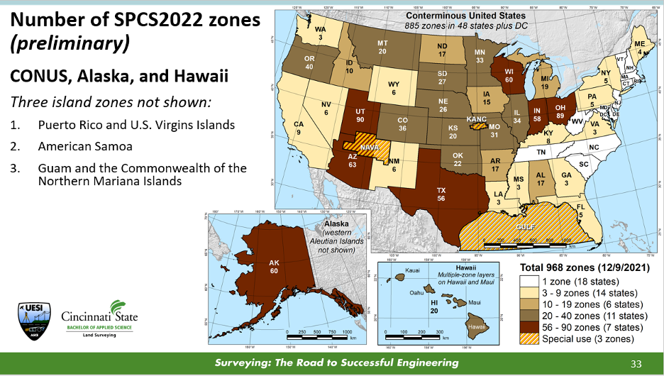
In my opinion, chapter 3, “Map Projections and Local Coordinates Systems” by Michael Dennis, does the best job of explaining the concepts of map projections that are relevant to the surveying and mapping community. Many GIS practitioners use map projections in their software but don’t have a working knowledge of what’s happening to their original data. This chapter describes the current United States State Plane Coordinate System of 1983 (SPCS83) and the future State Plane Coordinate System of 2022 (SPCS2022) that is scheduled to be adopted in 2025. Dennis uses figures and diagrams to describe map projections, angular and linear distortion, and methods for reducing map projection distortion to make it easier for readers to understand the concepts. One section of interest to many surveyors after SPCS2022 is adopted is the Low-Distortion Projection (LDP) Coordinate Systems section. This is useful because, in SPCS2022, many states have designed LDP systems for their state’s SPCS2022. The box below provides a diagram with the number of zones for each state.
Image: NGS Presentations Webpage “Grids for the Future: A New Approach for Designing State Plane Coordinate System Zones” by Michael Dennis.
One purpose of an LDP is to reduce linear distortion; it is not a new concept. Many surveyors have performed a simplified form of it for decades. It’s known by many as a “modified” or “scaled” State Plane. The American Congress on Surveying and Mapping (ACSM) taught a workshop for decades describing how to compute a “modified” State Plane Coordinate. I was an instructor of this class in the 1980s and 1990s. “Modified” State Plane Coordinates had several issues, but they worked reasonably well in small areal extents. Today, with the advancements in computers and computer software, there are better ways to accomplish an LDP. Dennis’ section does a great job explaining the new SPCS2022 and the design of LDPs in the SPCS2022. The use-case examples provide a simplified description of understanding the linear distortion behavior in an area.
Chapter 4, “Local, Regional, and Global Coordinate Transformation” by Michael Dennis, is one that every surveyor and GIS practitioner should read. Dennis highlighted the differences between “equation-based” transformations and “grid-based” transformations, as well as combined equation-based transformations with grid-based transformations. Understanding the information provided in chapter 4 will be important when NGS replaces the NAD 83 (2011) and NAVD 88 datums with the new, modernized NSRS in 2025. NGS will provide models and tools for users to perform coordinate transformations, but hopefully, some users will want to understand what’s happening behind the scenes.
Chapters 8 and 9 discuss laser scanning systems. In chapter 8, “Terrestrial Laser Scanning,” the “Data Quality Considerations” section highlights common artifacts or limitations encountered with terrestrial lidar system data. The authors provide many examples of these artifacts, making the concept easy to understand. At the end of this chapter, there are 14 pages of references that will be very helpful to users involved with terrestrial laser scanning systems.
Chapter 9, “Mobile Terrestrial Laser Scanning and Mapping,” is very informative, especially the section on georeferencing. This section is not just the description of properly using GNSS to perform a survey, but also the integration of various instruments to create an accurate mobile mapping system. I like how the authors discussed the error sources in georeferencing the system, listed the source, and provided an explanation of the error.
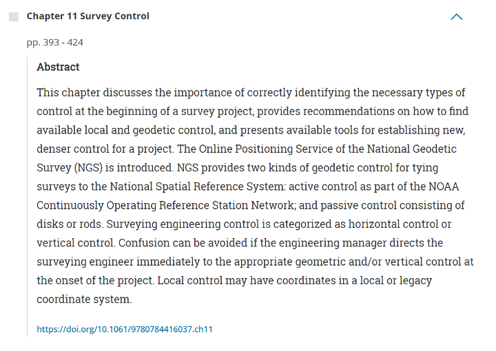
Anyone performing a GNSS survey project that meets NGS’s requirements needs to read chapter 11. I like the section describing how users should evaluate CORSs before using them as control. Evaluating CORS is something all users should do before using any CORS in their project, because not all CORS are created equal. See the excerpt from chapter 11 below for the recommended steps from the author.
Excerpt from Chapter 11 – Steps for Evaluation of CORS
The author recommends the following steps:
1. Choose stations that are within 100-300 km of a project site. It is well known that errors in GNSS baseline processing are directly correlated with baseline length (Chapter 6). Tropospheric delay is reduced when baselines are shorter and atmospheric conditions at each end of the line are similar. In addition, mutual satellite visibility at each end of the line for differencing diminishes as baselines grow longer. That said, errors in GNSS processing are more occupation time-dependent than baseline length-dependent (Eckl et al. 2001). Therefore, for short GNSS sessions (i.e., < 2 hours), choose CORS within approximately 100 km as control; for moderate GNSS sessions (i.e., 2 to 8 h), choose CORS within approximately 300 km. Note that even longer baselines can be successfully processed when GNSS sessions are very long in duration (e.g., up to 2,000 km for 24 h sessions).
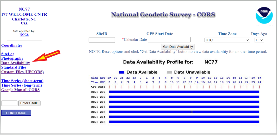
2. Determine if GNSS data are available at a given CORS during the time of your survey. Of course, if data are unavailable, then the station simply cannot be used as control. NGS provides a tool known as “User Friendly CORS (UFCORS)” for entering a date and time range to view available data at a given station (NGS 2021c). This tool can also be used to download the raw GNSS data for processing and adding a station to the survey network.
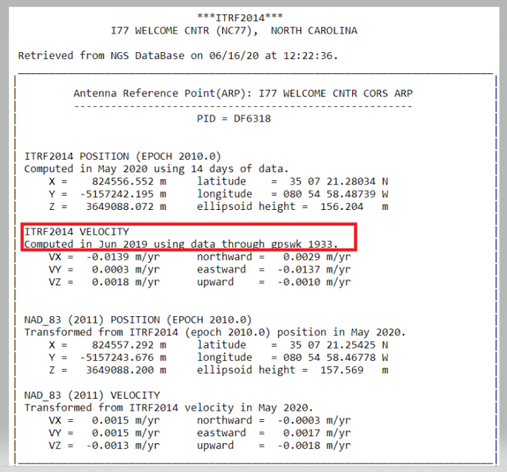
3. As discussed previously and when possible, choose a CORS with computed velocities rather than modeled velocities from HTDP. NGS provides tables of official coordinates with “computed” versus “htdp” coordinates and velocities on the website for CORS.
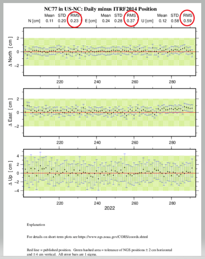
4. Review the aforementioned short-term time-series plot for the station, ideally at the time of the project. Stations with large spikes, data gaps, bias from the published “red” line, or large standard deviations should be avoided. A good rule-of-thumb is for the RMS in the short-term time-series plot (Figure 11-2) to be less than 1.0 cm in north and east and 2.0 cm in the up direction in a local geodetic horizon frame at the station.
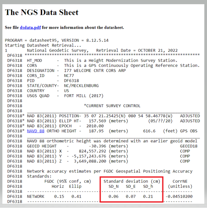
5. Examine the formal uncertainties for the official coordinates of the CORS. Standard deviations in north, east, and up are provided on the station’s datasheet, accessible from the webpage for the CORS (more on datasheets are discussed in the following under Passive Control). Stations with unusually large standard deviations (> 3 cm) should be avoided. Note that standard deviations are not available for CORSs with modeled velocities.
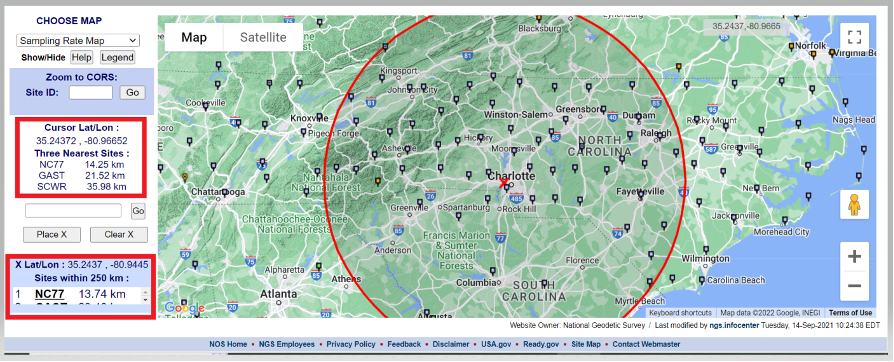
I believe that the evaluation of NOAA CORS is critical, so I’ve described Dan Gillins’ “Steps for Evaluation of CORS” below. First, users can access the NOAA CORS using the NGS CORS Map utility. After the map appears, users can move the cursor over the center of the project area, where it provides the location of the cursor and the three closest CORS. Users can click on a CORS icon and get coordinates and other information about the CORS. Also, they can place an X on the map, and the utility will draw a 250-km circle around the point. The box in the lower left-hand side of the map provides a list of the sites within 250 km of the marked location.
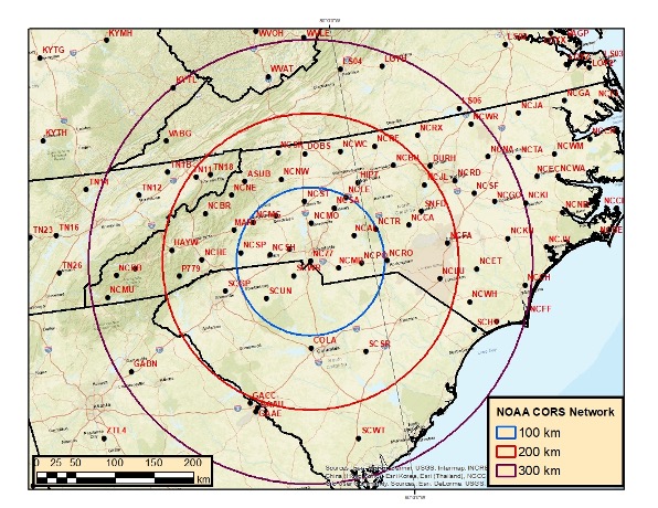
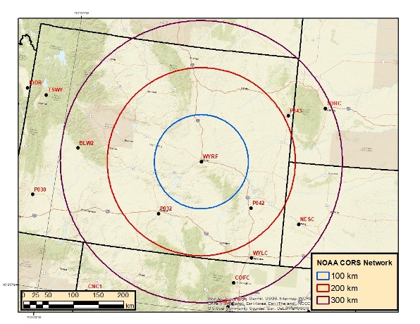
Users can download the NOAA CORS coordinates and velocities (computed and modeled). I downloaded the files and plotted three circles (with radii of 100, 200, and 300 km) around CORS NC77 in Charlotte, North Carolina. I only plotted CORS that are operational and have computed velocities. North Carolina has a lot of CORS to select from. In contrast, I’ve plotted three circles (also with radii of 100, 200 and 300 km) around CORS WYRF in Casper, Wyoming.
Buffer Zones around Charlotte, NC
Image: Dave Zilkoski
The plot depicting the buffer zones around Casper indicates that there are no CORS within the 100-km circle and only a few between 100 and 200 km.
Buffer Zones around Casper
Image: Dave Zilkoski
The data availability of the CORS site can be obtained by clicking on the CORS icon, selecting “Get Site Information,” and then selecting “Data Availability.”
There are too many chapters to describe each one, but I encourage users to check each chapter’s abstract on the ASCE website and decide which ones would be the most beneficial to them (see the box titled “Abstract for Chapter 11 Survey Control”). The manual provides numerous references and can serve as a helpful resource for finding further details on the fields of geodesy and surveying.
A goal of mine is for some readers of this column to obtain enough knowledge to “whet their appetite” and encourage them to pursue an education in geodesy and surveying. Others who are influential in federal government programs and those responsible for geospatial research for industries will recognize the need for more trained geodesists in the United States and help by doing the following:
actively market geodesy in high schools as a rewarding career for the math stars before college entry
build back, support, and sponsor geodesy programs at select universities; this support needs to be strategic with backing from the highest levels of the U.S. government
encourage U.S. government support in the form of grants, professional development of staff, and research collaborations/affiliations.
According to Fact.MR, a market research and competitive intelligence provider, the global surveying and mapping services market was worth US$9 billion in 2021 and is expected to expand at a CAGR of 3% during the forecast years of 2022-2032.
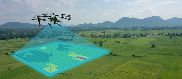
The survey and mapping industry has significantly benefited from drone technologies, because UAVs are less expensive and more accessible compared to traditional methods. Conventional surveying methods require rental aircraft and trained pilots, along with attached recording instruments — a costly and resource-intensive process. The introduction of UAVs has substantially created a future opportunity for surveying and mapping services to gather spatial information in a tighter structure. This also allows the collection of geospatial information with easy storage, processing and sharing capabilities.
For instance, in May 2022, India-based software company PDRL introduced a software-as-a-service platform — DroneNaksha — under the Svamitva Yojana scheme by the government of India for mapping land parcels using drone technology across the country. Similarly, in March 2022, Australia-based Emesent introduced Hovermap ST autonomous drone lidar mapping and surveying payload.
The integration of advanced technologies such as Wi-Fi, first-person view cameras, and GPS technology to make UAVs highly flexible and eliminate the need for a skilled pilot is expected to stimulate the demand for drones for survey and mapping activities, thereby driving market expansion.
Key Takeaways
The global surveying and mapping services market is projected to expand at a CAGR of 3.4% and reach US$13 billion by 2032.
Over the 2017-2021 historical period, the market evolved at 3.2% CAGR.
Forestry and agriculture account for a leading share in the market at a valuation of US$1.80 billion in 2021.
North America and East Asia account for leading shares in the global mapping services market at 24% and 32%, respectively.
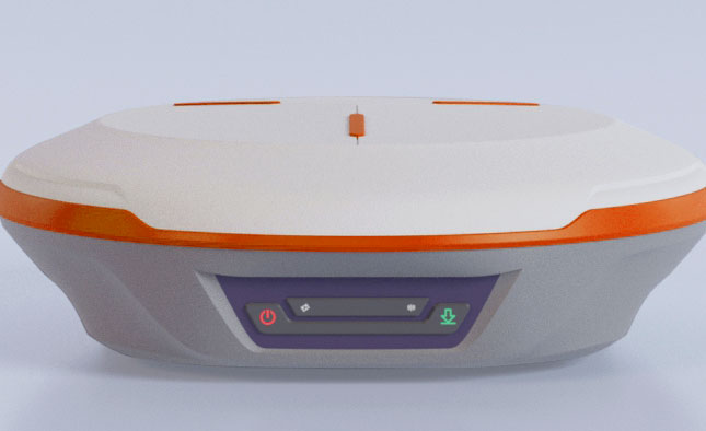
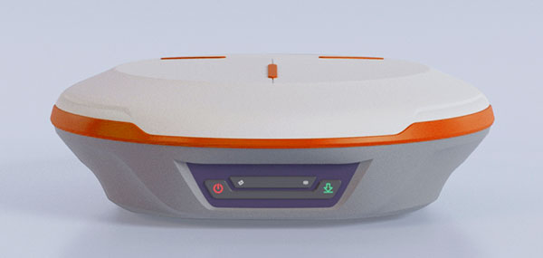
ComNav Technology Ltd. has released the N2 Palm RTK GNSS receiver. The release coincides with the company’s 10th anniversary. With its advanced technologies, the N2 is suitable for surveying, mapping and construction.
The N2 has a highly integrated main board and a three-in-one antenna, yet is extremely thin and portable, weighing about the same as a basketball (0.72 kg with battery) and measuring 48 mm, the thickness of AirPods.
Powered by ComNav’s SinoGNSS K8 high-precision module, the N2 can track 1,590 channels, including all existing and planned signals of GPS, BDS-2, BDS-3, GLONASS, Galileo, QZSS and SBAS. Its advanced satellite-tracking technology ensures it works well even in harsh environments, such as under heavy foliage or close to buildings.
A third-generation inertial measurement unit (IMU) makes the N2 immune to magnetic disturbance, which greatly improves its reliability. Pole-tilt compensation of up to 60° allows surveyors to locate difficult points precisely and easily while maintaining positioning accuracy within 2.5 cm. By using the company’s Quantum algorithm, the N2 achieves calibration-free operation — after 10 seconds of initialization, users can make tilt measurements with centimeter-level accuracy for an extended period, greatly improving efficiency.
With its integrated UHF modem, the N2 can reach a working range of up to 15 km. It can be used as either a base station or a rover.
The N2 features a 10,000 mAh intelligent Li-ion battery, along with ComNav’s patented low-power-consumption technology. It fully charges in five hours and works continuously in the field for 20 hours. The built-in USB-C port makes it convenient to charge with standard smartphone chargers or external power banks.
As with ComNav’s other products, the N2 meets ComNav’s high quality and durability standards; it is rated IP67 (dustproof and waterproof) and can work in temperatures from –35° C to +65° C. It can be used in a wider range of outdoor working conditions.
With near-field communication (NFC), the N2 can connect to other NFC-enabled devices, such as the R60 data collector. V5.0 dual-mode Bluetooth inside allows users to connect at ultra-long distances with low energy requirements.
The N2 Palm RTK GNSS receiver now is available through ComNav Technology authorized local distributors or directly from ComNav Technology.
The new device will ship in the fourth quarter of this year and is available for pre-order
Juniper Systems is entering the 10-inch rugged tablet market with the launch of its Mesa Pro rugged tablet. The Mesa Pro features 11th Generation Intel Core processors, a Windows 11 operating system, device customization options, a large sunlight-readable display and “Juniper Rugged” company design.
“We are excited to be entering the 10-inch rugged tablet segment for the first time,” said Darren Hellstern, the Mesa Pro product manager at Juniper Systems. “Mesa Pro offers powerful processing, a rugged design meant for any environment, and is a versatile workstation that can be used in the office or the field.”
Standard Mesa Pro units come equipped with an 11th Gen Intel Core i5 processor and 16 GB of LPDDR4x RAM. Core i7 and Celeron versions of the device are also available.
Each Mesa Pro configuration offers powerful performance and allows users to select a level of computing performance that best fits their needs while having options that meet their budgets.
“It was important for us to offer performance tiers,” said Hellstern. “This is the first time we have offered various performance levels in one of our devices. The needs that our customers and users have varies greatly. From running CAD programs, viewing construction plans, mapping and mounted-vehicle solutions, we feel that we have an offering with Mesa Pro that fits the processing need of the user. We are also available to help users determine what level of performance they need.”
Mesa Pro joins the current Mesa family of 7-inch devices and helps Juniper Systems achieve its mission of providing powerful rugged computing and data-collection devices to mobile field workers everywhere. The Mesa 3 runs on either Windows or Android operating systems. The Mesa family started in 2010 with the launch of the Mesa Rugged Notepad.
“Mesa devices have served our customers for over a decade,” said Hellstern. “We are proud to add Mesa Pro to that list of incredible devices and offer more options to our customers and users around the world.”
Juniper Systems is now accepting pre-orders for the Mesa Pro.
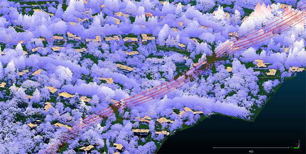
Teren, a climate resilience analytics company, has expanded its Premium 4D Content program for regions across the United States, including the Gulf Coast, Midwest, Rocky Mountains and West Coast.
Teren acquires and quickly processes high-fidelity lidar data, making it available via its content library, and delivers analytics with actionable insights to energy and engineering firms.
“Climate change is causing drought, flooding, landslides and wildfires across the country – significantly impacting asset owners and project developers. As a result, the market demand for high-fidelity, temporal data to identify, prioritize, and monitor climate-related risk is higher than ever,” said Toby Kraft, Teren CEO.
Teren is amassing a content library of remotely-sensed 3D (spatial) data across the United States. That data is updated on regular intervals to monitor changes over time providing a unique 4D (temporal) view. This 4D data library feeds analytics that identify risk, inform mitigation, and strengthen asset resilience. While remotely-sensed data has traditionally been sourced on a project-by-project basis, Teren offers its data and analytics as a subscription service. This model drives down the costs for clients and stakeholders, helping to maximize the speed of delivery, return on investment, and data value.
“In our flagship content region, Appalachia, our customers tap into our 4D content library to identify and monitor the terrain and surface conditions surrounding their assets — primarily aiming to identify and mitigate landslides before they become catastrophic incidents,” Kraft said. “We’re expanding the program nationwide to meet the growing demand for terrain monitoring and climate resilience analytics around events such as erosion, flooding, wildfires and more.”
Teren’s solution saved clients in Appalachia an estimated $152 million annually, preventing 24 failures per year due to landslides. While landslides are not as pervasive across the United States, companies can apply the data and analytics suite for the following:
Gulf Coast: inundation, subsidence, land movement
Midwest: erosion, flooding, subsidence
Rock Mountains: landslides, flooding, wildfire
West Coast: wildfires, land movement, flooding.
Traditionally used by the energy sector, Teren’s data has also proven to be highly valuable to state and federal agencies, insurers and civil engineers. Teren expects to see increased variability across clients and use cases as the content region expands.
To learn more about Teren or to request a demo, visit www.teren4d.com.