Tag: OEM

  • Innovation: Getting Along

    Innovation: Getting Along

    Collaborative Navigation in Transitional Environments

    By Dorota A. Grejner-Brzezinska, J.N. (Nikki) Markiel, Charles K. Toth and Andrew Zaydak

    GPS World photo
    INNOVATION INSIGHTS by Richard Langley

    COLLABORATION,  n. /kəˌlæbəˈreɪʃən/, n. of action. United labour, co-operation; esp. in literary, artistic, or scientific work — according to the Oxford English Dictionary. Collaboration is something we all practice, knowingly or unknowingly, even in our everyday lives. It generally results in a more productive outcome than acting individually. In scientific and engineering circles, collaboration in research is extremely common with most published papers having multiple authors, for example.

    The term collaboration can be applied not only to the endeavors of human beings or other living creatures but also to inanimate objects, too. Researchers have developed systems of miniaturized robots and unmanned vehicles that operate collaboratively to complete a task. These platforms must navigate as part of their functions and this navigation can often be made more continuous and accurate if each individual platform navigates collaboratively in the group rather than autonomously. This is typically achieved by exchanging sensor measurements by some kind of short-range wireless technology such as Wi-Fi, ultra-wide band, or ZigBee, a suite of communication protocols for small, low-power digital radios based on an Institute of Electrical and Electronics Engineers’ standard for personal area networks.

    A wide variety of navigation sensors can be implemented for collaborative navigation depending on whether the system is designed by outdoor use, for use inside buildings, or for operations in a wide variety of environments. In addition to GPS and other global navigation satellite systems, inertial measurement units, terrestrial radio-based navigation systems, laser and acoustic ranging, and image-based systems can be used.

    In this month’s article, a team of researchers at The Ohio State University discusses a system under development for collaborative navigation in transitional environments — environments in which GPS alone is insufficient for continuous and accurate navigation. Their prototype system involves a land-based deployment vehicle and a human operator carrying a personal navigator sensor assembly, which initially navigate together before the personal navigator transitions to an indoor environment. This system will have multiple applications including helping first responders to emergencies. Read on.

    “Innovation” is a regular feature that discusses advances in GPS technology andits applications as well as the fundamentals of GPS positioning. The column is coordinated by Richard Langley of the Department of Geodesy and Geomatics Engineering, University of New Brunswick. He welcomes comments and topic ideas. To contact him, see the “Contributing Editors” section on page 6.


    Collaborative navigation is an emerging field where a group of users navigates together by exchanging navigation and inter-user ranging information. This concept has been considered a viable alternative for GPS-challenged environments. However, most of the developed systems and approaches are based on fixed types and numbers of sensors per user or platform (restricted in sensor configuration) that eventually leads to a limitation in navigation capability, particularly in mixed or transition environments.

    As an example of an applicable scenario, consider an emergency crew navigating initially in a deployment vehicle, and, when subsequently dispatched, continuing in collaborative mode, referring to the navigation solution of the other users and vehicles. This approach is designed to assure continuous navigation solution of distributed agents in transition environments, such as moving between open areas, partially obstructed areas, and indoors when different types of users need to maintain high-accuracy navigation capability in relative and absolute terms.

    At The Ohio State University (OSU), we have developed systems that use multiple sensors and communications technologies to investigate, experimentally, the viability and performance attributes of such collaborative navigation. For our experiments, two platforms, a land-based deployment vehicle and a human operator carrying a personal navigator (PN) sensor assembly, initially navigate together before the PN transitions to the indoor environment.

    In the article, we describe the concept of collaborative navigation, briefly describe the systems we have developed and the algorithms used, and report on the results of some of our tests. The focus of the study being reported here is on the environment-to-environment transition and indoor navigation based on 3D sensor imagery, initially in post-processing mode with a plan to transition to real time.

    The Concept

    Collaborative navigation, also referred to as cooperative navigation or positioning, is a localization technique emerging from the field of wireless sensor networks (WSNs). Typically, the nodes in a WSN can communicate with each other using wireless communications technology based on standards, such as Zigbee/IEEE 802.15.4. The communication signals in a WSN are used to derive the inter-nodal distances across the network. Then, the collaborative navigation solution is formed by integrating the inter-nodal range measurements among nodes (users) in the network using a centralized or decentralized Kalman filter, or a least-squares-based approach.

    A paradigm shift from single to multi-sensor to multi-platform navigation is illustrated conceptually in Figure 1. While conventional sensor integration and integrated sensor systems are commonplace in navigation, sensor networks of integrated sensor systems are a relatively new development in navigation. Figure 2 illustrates the concept of collaborative navigation with emphasis on transitions between varying environments. In actual applications, example networks include those formed by soldiers, emergency crews, and formations of robots or unmanned vehicles, with the primary objective of achieving a sustained level of sufficient navigation accuracy in GPS-denied environments and assuring seamless transition among sensors, platforms, and environments.

    Source: Dorota A. Grejner-Brzezinska, J.N. (Nikki) Markiel, Charles K. Toth and Andrew Zaydak
    Figure 1. Paradigm shift in sensor integration concept for navigation.
    Source: Dorota A. Grejner-Brzezinska, J.N. (Nikki) Markiel, Charles K. Toth and Andrew Zaydak
    Figure 2. Collaborative navigation and transition between varying environments.

    Field Experiments and Methodology

    A series of field experiments were carried out in the fall of 2011 at The Ohio State University (OSU), and in the spring of 2012 at the Nottingham Geospatial Institute of the University of Nottingham, using the updated prototype of the personal navigator developed earlier at the OSU Satellite Positioning and Inertial Navigation Laboratory, and land-based multisensory vehicles. Note that the PN prototype is not a miniaturized system, but rather a sensor assembly put together using commercial off-the-shelf components for demonstration purposes only.

    The GPSVan (see Figure 3), the OSU mobile research navigation and mapping platform, and the recently upgraded OSU PN prototype (see Figure 4) jointly performed a variety of maneuvers, collecting data from multiple GPS receivers, inertial measurement units (IMUs), imaging sensors, and other devices. Parts of the collected data sets have been used for demonstrating the performance of navigation indoors and in the transition between environments, and it is this aspect of our experiments that will be discussed in the present article.

    Source: Dorota A. Grejner-Brzezinska, J.N. (Nikki) Markiel, Charles K. Toth and Andrew Zaydak
    Figure 3. Land vehicle, OSU GPSVan.
    Source: Dorota A. Grejner-Brzezinska, J.N. (Nikki) Markiel, Charles K. Toth and Andrew Zaydak
    Figure 4. Personal navigator sensor assembly.

    The GPSVan was equipped with navigation, tactical, and microelectromechanical systems (MEMS)-grade IMUs, installed in a two-level rigid metal cage, and the signals from two GPS antennas, mounted on the roof, were shared among multiple geodetic-grade dual-frequency GPS receivers. In addition, odometer data were logged, and optical imagery was acquired in some of the tests.

    The first PN prototype system, developed in 2006–2007, used GPS, IMU, a digital barometer, a magnetometer compass, a human locomotion model, and 3D active imaging sensor, Flash LIDAR (an imaging light detection and ranging system using rapid laser pulses for subject illumination). Recently, the design was upgraded to include 2D/3D imaging sensors to provide better position and attitude estimates indoors, and to facilitate transition between outdoor and indoor environments. Consequently, the current configuration allows for better distance estimation among platforms, both indoors and outdoors, as well as improving the navigation and tracking performance in general.

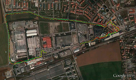
    The test area where data were acquired to support this study, shown in Figure 5, includes an open parking lot, moderately vegetated passages, a narrow alley between buildings, and a one-storey building for indoor navigation testing. The three typical scenarios used were:
    1)    Sensor/platform calibration: GPSVan and PN are connected and navigate together.
    2)    Both platforms moved closely together, that is, the GPSVan followed the PN’s trajectory.
    3)    Both platforms moved independently.

    Source: Dorota A. Grejner-Brzezinska, J.N. (Nikki) Markiel, Charles K. Toth and Andrew Zaydak

    Image-Based Navigation

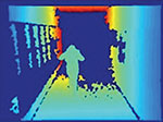
    The sensor of interest for the study reported here is an image sensor that actually includes two distinct data streams: a standard intensity image and a 3D ranging image, see Figure 6. The unit consists primarily of a 640 × 480 pixel array of infrared detectors. The operational range of the sensor is 0.8–10 meters, with a range resolution of 1 centimeter at a 2-meter distance.

    Source: Dorota A. Grejner-Brzezinska, J.N. (Nikki) Markiel, Charles K. Toth and Andrew Zaydak
    Figure 6. PN captured 3D image sequence from inside the building.

    In this study, the image-based navigation (no IMU) was considered. To overcome this limitation, the intensity images acquired simultaneously with the range data by the unit were leveraged to provide crucial information. The two intensity images were processed utilizing the Scale Invariant Feature Transform (SIFT) algorithm to identify matching features between the pair of 2D intensity images.

    The SIFT algorithm has been primarily applied to 1D and 2D imagery to date; the authors are not aware of any research efforts to apply SIFT to 3D datasets for the expressed purpose of positioning. Analysis at our laboratory supported well-published results regarding the exceptional performance of SIFT with respect to both repeatability and extraction of the feature content. The algorithm is remarkably robust to most image corruption schema, although white noise above 5 percent does appear to be the primary weakness of the algorithm. The algorithm suffers in three critical areas with respect to providing a 3D positioning solution. First, the algorithm is difficult to scale in terms of the number of descriptive points; that is, the algorithm quickly becomes computationally intractable for a large number (>5,000) of pixels. Secondly, the matching process is not unique; it is exceptionally feasible for the algorithm to match a single point in one image to multiple points in another image. Finally, since the algorithm loses spatial positioning capabilities to achieve the repeatability, the ability to utilize matching features for triangulation or trilateration becomes impaired. Owing to the noted issues, SIFT was not found to be a suitable methodology for real-time positioning based on 3D Flash LIDAR datasets.

    Despite these drawbacks, the intensity images offer the only available sensor input beyond the 3D ranging image. As such, the SIFT methodology provides what we believe to be a “best in class” algorithmic approach for matching 2D intensity images. The necessity of leveraging the intensity images will be apparent shortly, as the schema for deriving platform position is explained.

    The algorithm has been developed and implemented by the second author (see Further Reading for details). The algorithm utilizes eigenvector “signatures” for point features as a means to facilitate matching. The algorithm is comprised of four steps:
    1)    Segmentation
    2)    Coordinate frame transformation
    3)    Feature matching
    4)    Position and orientation determination.

    The algorithm utilizes the eigenvector descriptors to merge points likely to belong to a surface and identify the pixels corresponding to transitions between surfaces. Utilizing an initial coarse estimate from the IMU system, the results from the previous frame are transformed into the current coordinate reference frame by means of a Random Sampling Consensus or RANSAC methodology. Matching of static transitional pixels is accomplished by comparing eigenvector “signatures” within a constrained search window. Once matching features are identified and determined to be static, the closed form quaternion solution is utilized to derive the position and orientation of the acquisition device, and the result updates the inertial system in the same manner as a GPS receiver within the common GPS/IMU integration. The algorithm is unique in that the threshold mechanisms at each step are derived from the data itself, rather than relying upon a-priori limits. Since the algorithm only utilizes transitional pixels for matching, a significant reduction in dimensionality is generally accomplished and facilitates implementation on larger data frames.

    The key point in this overview is the need to provide coarse positioning information to the 3D matching algorithm to constrain the search space for matching eigenvector signatures. Since the IMU data were not available, the matching SIFT features from the intensity images were correlated with the associated range pixel measurements, and these range measurements were utilized in Horn’s Method (see Further Reading) to provide the coarse adjustment between consecutive range image frames. The 3D-range-matching algorithm described above then proceeds normally.

    The use of SIFT to provide the initial matching between the images entails the acceptance of several critical issues, beyond the limitations previously discussed. First, since the SIFT algorithm is matching 2D features on the intensity image; there is no guarantee that the matched features represent static elements in the field of view. As an example, SIFT can easily “match” the logo on a shirt worn by a moving person; since the input data will include the position of non-static elements, the resulting coarse adjustment may possess very large biases (in position). If these biases are significant, constraining the search space may be infeasible, resulting in either the inability to generate eigenvector matches (worst case) or a longer search time (best case). Since the 3D-range-matching algorithm checks the two range images for consistency before the matching process begins, this can be largely mitigated in implementation. Secondly, the SIFT features are located with sub-pixel location, thus the correlation to the range pixel image will inherently possess an error of ± 1 pixel (row and column). The impact of this error is that range pixels utilized to facilitate the coarse adjustment may in fact not be correct; the correct range pixel to be matched may not be the one selected. This will result in larger errors during the initial (coarse) adjustment process. Third, the uncertainty of the coarse adjustment is not known, so a-priori estimates of the error ellipse must be made to establish the eigenvector search space. The size and extent of these error ellipses is not defined on-the-fly by the data, which reduces one of the key elements of the 3D matching algorithm. Fourth, the limited range of the image sensor results in a condition where intensity features have no associated range measurement (the feature is out of range for the range device). This reduces the effective use of SIFT features for coarse alignment. However, using the intensity images does demonstrate the ability of the 3D-range-matching algorithm to generically utilize coarse adjustment information and refine the result to provide a navigation solution.

    Data Analysis

    In the experiment selected for discussion in this article, initially, the PN was initially riding in the GPSVan. After completing several loops in the parking lot (the upper portion of Figure 5), the PN then departed the vehicle and entered the building (see Figure 7), exited the facility, completed a trajectory around the second building (denoted as “mixed area” in Figure 5), and then returned to the parking lot.

    Source: Dorota A. Grejner-Brzezinska, J.N. (Nikki) Markiel, Charles K. Toth and Andrew Zaydak
    Figure 7. Building used as part of the test trajectory for indoor and transition environment testing; yellow line: nominal personal navigator indoor trajectories; arrows: direction of personal navigator motion inside the building; insert: reconstructed trajectory section, based on 3D image-based navigation.

    While minor GPS outages can occur under the canopy of trees, the critical portion of the trajectory is the portion occurring inside the building since the PN platform will be unable to access the GPS signal during this portion of the trajectory. Our efforts are therefore focused on providing alternative methods for positioning to bridge this critical gap.

    Utilizing the combined intensity images (for coarse adjustment via SIFT) and the 3D ranging data, a trajectory was derived for travel inside the building at the OSU Supercomputing Facility. There is a finite interval between exiting the building and recovery of GPS signal lock during which the range acquisition was not available; thus the total extent of travel distance during GPS signal outage is not precisely identical to the travel distance where 3D range solutions were utilized for positioning. We estimate the distance from recovery of GPS signals to the last known 3D ranging-derived position to be approximately 3 meters. Based upon this estimate, the travel distance inside the building should be approximately 53.5 meters (forward), 9.5 meters (right), and 0.75 meters (vertical). Based upon these estimates, the total misclosure based upon 3D range-derived positions is provided in Table 1. The asterisk in the third row indicates the estimated nature of these values.

    Source: Dorota A. Grejner-Brzezinska, J.N. (Nikki) Markiel, Charles K. Toth and Andrew Zaydak
    Table 1. Approximate positional results for the OSU Supercomputing Facility trajectory.

    The average positional uncertainty reflects the relative, frame-to-frame error reported by the algorithm during the indoor trajectory. This includes both IMU and 3D ranging solutions. The primary reason for the rather large misclosure in the forward and vertical directions is the result of three distinct issues. First, the image ranging sensor has a limited range; during certain portions of the trajectory the sensor is nearly “blind” due to lack of measurable features within the range. During this period, the algorithm must default to the IMU data, which is known to be suspect, as previously discussed. Secondly, the correlation between SIFT features and range measurement pixels can induce errors, as discussed above. Third, the 3D range positions and the IMU data were not integrated in this demonstration; the range positions were used to substitute for the lost GPS signals and the IMU was drifting. Resolving this final issue would, at a minimum, reduce the IMU drift error and improve the overall solution.

    A follow-up study conducted at a different facility was completed using the same platform and methodology. In this study, a complete traverse was completed indoors forming a “box” or square trajectory, which returned to the original entrance point. A plot of the trajectory results is provided in Figure 8. The misclosure is less than four meters with respect to both the forward (z) and right (x) directions. While similar issues exist with IMU drift (owing to lack of tight integration with the ranging data), a number of problems between the SIFT feature/range pixel correlation portion of the algorithm are evident; note the large “clumps’ of data points, where the algorithm struggles to reconcile the motions reported by the coarse (SIFT-derived) position and the range-derived position.

    Source: Dorota A. Grejner-Brzezinska, J.N. (Nikki) Markiel, Charles K. Toth and Andrew Zaydak
    Figure 8. Indoor scenario: square (box) trajectory.

    Conclusions

    As demonstrated in this paper, the determination of position based upon 3D range measurements can be seen to have particular potential benefit for the problem of navigation during periods of operation in GPS-denied environments. The experiment demonstrates several salient points of use in our ongoing research activities. First, the effective measurement range of the sensor is paramount; the trivial (but essential) need to acquire data is critical to success. A major problem was the presence of matching SIFT features but no corresponding range measurement. Second, orientation information is just as critical as position; the lack of this information significantly extended the time required to match features (via eigenvector signatures). Third, there is a critical need for the sensor to scan not only forward (along the trajectory) but also right/left and up/down. Obtaining features in all axes would support efforts to minimize IMU drift, particularly in the vertical. Alternatively, a wider field of view could conceivably accomplish the same objective. Finally, the algorithm was not fully integrated as a substitute for GPS positioning and the IMU was free to drift. Since the 3D ranging algorithm cannot guarantee a solution for all epochs, accurate IMU positioning is critical to bridge these outages. Fully integrating the 3D ranging solution with a GPS/IMU/3D schema would significantly reduce positional errors and misclosure.

    Our study indicates that leveraging 3D ranging images to achieve indoor relative (frame-to-frame) positioning shows great promise. The utilization of SIFT to match intensity images was an unfortunate necessity dictated by data availability; the method is technically feasible but our efforts would suggest there are significant drawbacks to this application, both in terms of efficiency and positional accuracy. It would be better to use IMU data with orientation solutions to derive the best possible solution. Our next step is the full integration within the IMU to enable 3D ranging solutions to update the ongoing trajectory, which we believe will reduce the misclosure and provide enhanced solutions supporting autonomous (or semi-autonomous) navigation.

    Acknowledgments

    This article is based on the paper “Cooperative Navigation in Transitional Environments,” presented at presented at PLANS 2012, the Institute of Electrical and Electronics Engineers / Institute of Navigation Position, Location and Navigation Symposium held in Myrtle Beach, South Carolina, April 23–26, 2012.

    Manufacturers

    The equipment used for the experiments discussed in this article included a NovAtel Inc. SPAN system consisting of a NovAtel OEMV GPScard, a Honeywell International Inc. HG1700 Ring Laser Gyro IMU, a Microsoft Xbox Kinect 3D imaging sensor, and a Casio Computer Co., Ltd. Exilim EX-H20G Hybrid-GPS digital camera.


    DOROTA GREJNER-BRZEZINSKA is a professor and leads the Satellite Positioning and Inertial Navigation (SPIN) Laboratory at OSU, where she received her M.S. and Ph.D. degrees in geodetic science.

    J.N. (NIKKI) MARKIEL is a lead geophysical scientist at the National Geospatial-Intelligence Agency. She obtained her Ph.D. in geodetic engineering at OSU.

    CHARLES TOTH is a senior research scientist at OSU’s Center for Mapping. He received a Ph.D. in electrical engineering and geoinformation sciences from the Technical University of Budapest, Hungary.

    ANDREW ZAYDAK is a Ph.D. candidate in geodetic engineering at OSU.

    FURTHER READING

    ◾ The Concept of Collaborative Navigation

    “The Network-based Collaborative Navigation for Land Vehicle Applications in GPS-denied Environment” by J-K. Lee, D.A. Grejner-Brzezinska and C. Toth in the Royal Institute of Navigation Journal of Navigation; in press.

    “Positioning and Navigation in GPS-challenged Environments: Cooperative Navigation Concept” by D.A. Grejner-Brzezinska, J-K. Lee and C. K. Toth, presented at FIG Working Week 2011, Marrakech, Morocco,  May 18-22, 2011.

    “Network-Based Collaborative Navigation for Ground-Based Users in GPS-Challenged Environments” by J-K. Lee, D. Grejner-Brzezinska, and C.K. Toth in Proceedings of ION GNSS 2010, the 23rd International Technical Meeting of the Satellite Division of The Institute of Navigation, Portland, Oregon, September 21-24, 2010, pp. 3380-3387.

    ◾ Sensors Supporting Collaborative Navigation

    “Challenged Positions: Dynamic Sensor Network, Distributed GPS Aperture, and Inter-nodal Ranging Signals” by D.A. Grejner-Brzezinska, C.K. Toth, J. Gupta, L. Lei, and X. Wang in GPS World, Vol. 21, No. 9, September 2010, pp. 35-42.

    “Positioning in GPS-challenged Environments: Dynamic Sensor Network with Distributed GPS Aperture and Inter-nodal Ranging Signals” by D.A. Grejner-Brzezinska, C. K. Toth, L. Li, J. Park, X. Wang, H. Sun, I.J. Gupta, K. Huggins and Y. F. Zheng (2009): in Proceedings of ION GNSS 2009, the 22nd International Technical Meeting of the Satellite Division of The Institute of Navigation, Savannah, Georgia, September 22-25, 2009, pp. 111–123.

    “Separation of Static and Non-Static Features from Three Dimensional Datasets: Supporting Positional Location in GPS Challenged Environments – An Update” by J.N. Markiel, D. Grejner-Brzezinska, and C. Toth in Proceedings of ION GNSS 2007, the 20th International Technical Meeting of the Satellite Division of The Institute of Navigation, Fort Worth, Texas, September 25-28, 2007, pp. 60-69.

    ◾ Personal Navigation

    “Personal Navigation: Extending Mobile Mapping Technologies Into Indoor Environments” by D. Grejner-Brzezinska, C. Toth, J. Markiel, and S. Moafipoor in Boletim De Ciencias Geodesicas, Vol. 15, No. 5, 2010, pp. 790-806.

    “A Fuzzy Dead Reckoning Algorithm for a Personal Navigator” by S. Moafipoor, D.A. Grejner-Brzezinska, and C.K. Toth, in Navigation, Vol. 55, No. 4, Winter 2008, pp. 241-254.

    “Quality Assurance/Quality Control Analysis of Dead Reckoning Parameters in a Personal Navigator” by S. Moafipoor, D. Grejner-Brzezinska, C.K. Toth, and C. Rizos in Location Based Services & TeleCartography II: From Sensor Fusion to Context Models, G. Gartner and K. Rehrl (Eds.), Lecture Notes in Geoinformation & Cartography, Springer-Verlag, Berlin and Heidelberg, 2008, pp. 333-351.

    “Pedestrian Tracking and Navigation Using Adaptive Knowledge System Based on Neural Networks and Fuzzy Logic” by S. Moafipoor, D. Grejner-Brzezinska, C.K. Toth, and C. Rizos in Journal of Applied Geodesy, Vol. 1, No. 3, 2008, pp. 111-123.

    ◾ Horn’s Method

    “Closed-form Solution of Absolute Orientation Using Unit Quaternions” by B.K.P. Horn in Journal of the Optical Society of America, Vol. 4, No. 4, April 1987, p. 629-642.

  • Winning Experts to Discuss GNSS in November Webinar

    The winners of GPS World’s 2012 Leadership Awards will be featured in November webinar “The Future of GNSS Research & Development.” The webinar will be held Thursday, November 15, at 10 a.m. PDT / 1 p.m. ET / 5 p.m. GMT. Registration is free.

    The winners are expected to discuss with moderator and editor-in-chief Alan Cameron their significant recent achievement in four fields, as well as the future directions of their research or significant research that they think should be undertaken by others in the GNSS community.

    The invited speakers are:

    • Martin Unwin, Surrey Satellite Technology Limited. One of the driving forces behind the GIOVE-A satellite (recently retired) and the Galileo IOV satellites.
    • Todd Humphrey, Radionavigation Laboratory, University of Texas at Austin. Received the GPSW Signals Leadership Award. Leader of several seminal studies on spoofing and jamming; testified this summer before Congress on the subject.
    • Waldemar Kunysz, NextNav LLC. Received the GPSW Services Leadership Award for his work on WAPS (Widea Area Positioning System) design and implementation in the continental USA. He spent the previous 16 years with NovAtel on various research projects and novel antenna designs.
    • Robert Lutwak, Symmetricom. Received the GPSW Products Leadership Award for practical advances to overcome the intrinsic physical barriers to affordable chip-scale atomic clocks, enabling precision time and time transfer in mobile GNSS and communications systems.

    To register, visit our webinar page or go straight to the registration form.

  • Topcon Unveils B110 GNSS Receiver Board


    Topcon Positioning Systems announces the light, ultra-compact dual-frequency positioning engine, the B110 GNSS receiver board. The B110 is the first GNSS board with Topcon’s new Vanguard ASIC, supporting 226 universal channels for GPS, GLONASS and Galileo tracking and scalable positioning from sub-meter DGPS to sub-centimeter RTK.

    The B110 board’s small size, low power consumption and flexible communication interfaces make it easy to integrate into any precise positioning application, reducing the time-to-market for OEM customers.

    Features that facilitate easy integration include:

    • Compact 40 x 55mm footprint with low power consumption
    • 226 universal channels with GPS + GLONASS L1/L2, Galileo E1 and SBAS “all in view” tracking
    • High performance RTK engine
    • Industry-leading position update rate of 100Hz
    • SD/MMC card interfaces for quick and easy support for data logging – just add a memory card holder
    • Serial, USB, CAN, I2C, PPS and EVENTIN.
  • JAVAD Tracks L5 Signals from Indian GAGAN Satellite

    JAVAD GNSS has commented on some news that its receivers can track a new L5 signal from the Indian SBAS satellite, GSAT-8, launched on May 20.  In a further explanation to GPS World, CEO Javad Ashjaee explained, “All owners of our products can track it. The only thing is that if customers have not updated their firmware for a long time, they should update to recent firmwares released earlier. They need to update their firmware, which is free of charge and is posted on our website. All of our customers with recent firmware versions can track the GAGAN L5 signal.”

    An earlier report from CANSPACE that appeared on the GPS World website said, in part, “Although GSAT-8 reportedly carries a dual-frequency transponder, no L5 signals from this satellite have yet been detected by International GNSS Service tracking stations.”

    The JAVAD GNSS statement on September 30 said “Report of GPS World that GAGAN PRN127 does not transmit L5 signal is not correct. Our receivers track it.
 This graph shows code-phase measurements for this signal.” The web page displays this figure:


    A check with a University of Bern, Switzerland, report of stations participating in the IGS M-GEX campaign on October 2 found that a number of stations are tracking the L1 signal from GSAT-8 but none are tracking the L5 signal yet due to issues with receiver firmware. However, various stations in the Cooperative Network for GNSS Observation (formerly the Cooperative Network for GIOVE Observation, still abbreviated CONGO), using Javad Triumph receivers, have tracked GAGAN L1 and L5 signals for more than half a year. No detailed analysis of these measurements has been performed so far.

  • New BeiDou-2/Compass Satellites Begin Transmissions

    News courtesy of CANSPACE Listserv.


    The two BeiDou-2/Compass satellites launched on 18 September are now  in their circular medium Earth orbits and have started transmitting navigation signals. Several stations participating in the International GNSS Service’s Multi-GNSS Experiment as well as some in the Cooperative Network for GNSS Observation started tracking the satellites on 26 September.

    From NORAD/JSpOC, we have the following orbits for the new satellites:

    BEIDOU M5
    1 38774U 12050A   12272.66377655 -.00000046  00000-0  00000+0 0    87
    2 38774 055.0007 232.0409 0023106 183.4242 172.2126 01.86242137   380

    BEIDOU M6
    1 38775U 12050B   12275.26998096 -.00000027  00000-0  00000+0 0   220
    2 38775 055.1037 231.4461 0018364 210.8886 135.6552 01.86257715   424

    Satellite M5 is using PRN code 13 and M6 is using PRN code 14.

    A plot showing the argument of latitude vs. longitude of ascending node for the BeiDou-2/Compass MEO satellites, including the M1/C30 test satellite, can be downloaded.

    The plane spacing for the operational satellites is about 120 degrees. The slot spacings seem to be about 45 degrees.

  • Lockheed, Raytheon Complete First Launch Exercise for Next-Gen GPS Satellites

    Raytheon Company and Lockheed Martin have successfully completed the first launch readiness exercise for the U.S. Air Force’s next generation GPS III satellites. The exercise is a key milestone demonstrating the team remains on schedule to achieve launch availability in 2014, the companies said.

    The Lockheed Martin-built GPS III satellites and the Raytheon-developed next generation GPS operational control system, known as OCX, are critical elements of the U.S. Air Force’s effort to affordably replace aging GPS satellites while improving capability to meet the evolving demands of military, commercial and civilian users worldwide. This is the first space and ground enterprise successfully building the ground control and space vehicles by two independent prime contractors.

    The launch readiness exercise, completed over a three day period by mission operations personnel, validated the basic satellite command and control functions, tested the software and hardware interfaces and demonstrated basic on-console procedures required for space vehicle contacts during the launch and early orbit mission.  The event sets the stage for the first GPS III satellite’s mission readiness timeline, which includes five short-duration exercises and six, five-day mission rehearsals leading up tolaunch.

    “Completion of our first GPS III launch readiness exercise is a major milestone for the entire GPS enterprise and is a solid indictor that our space and ground segments are well synchronized,” said Col Bernie Gruber, the director of the U.S. Air Force’s Global Positioning Systems Directorate.

    To achieve first launch availability in the 2014 timeframe, the U.S. Air Force awarded Lockheed Martin and Raytheon contracts in January of this year to provide a Launch and Checkout Capability (LCC) for launch and early on-orbit testing of all GPS III satellites.  At the heart of the LCC is Raytheon’s Launch and Checkout System that will provide satellite command and control capability, an integral part of OCX’s  support of the first GPS III launch.

    “The completion of our first launch readiness exercise is an important milestone for the entire GPS enterprise,” said Keoki Jackson, vice president of Lockheed Martin’s Navigation Systems mission area. “This achievement is a testament to efficient planning and synchronization by the U.S. Air Force and demonstrates that we are on track to deliver critical GPS III capabilities to military, commercial and civilian users worldwide.”

    “This milestone represents the hard work and dedication of the entire GPS III and OCX government-industry team,” stated Ray Kolibaba, a vice president of Raytheon’s Intelligence and Information Systems business and GPS OCX program manager. “This is another demonstration of the rapid progress we’re making on OCX development, while maintaining GPS space-ground enterprise alignment. I’m confident that we’ll be prepared to support the first GPS III launch with an efficient, evolvable and secure ground control system built independently.”

    The GPS III team is led by the Global Positioning Systems Directorate at the U.S. Air Force Space and Missile Systems Center. Air Force Space Command, based at Schriever Air Force Base, Colo., manages and operates the GPS constellation for both civil and military users.

  • Innovation: Software GNSS Receiver

    Innovation: Software GNSS Receiver

    An Answer for Precise Positioning Research

    By Thomas Pany, Nico Falk, Bernhard Riedl, Tobias Hartmann, Günter Stangl, and Carsten Stöber

    Innovation Insights with Richard Langley
    Innovation Insights with Richard Langley

    WHAT IS THE IDEAL GNSS RECEIVER? Well, that depends on what you mean by “ideal.” If we take it to mean the simplest, conceptually, yet the most capable and adaptable receiver, then we would just connect an analog-to-digital converter (ADC) to an antenna and pass the converter’s output to a digital signal processor whose software would transform the received signal into the desired result with the utmost speed and precision. There are certain technological limitations that currently preclude fully developing such a device but we are getting very close to the ideal and practical implementations already exist.

    Such a GNSS receiver is an example of a software-defined radio — a radio-communications architecture in which as much of the operation of a receiver (or a transmitter) as feasible is performed by software in an embedded system or on a personal computer (PC).

    Now, we can’t simply connect an ADC to an antenna since the strength of GNSS signals falls well below the sensitivity threshold of real ADCs and those that can directly digitize microwave radio frequencies are rather power hungry. Therefore, the front end of a real software GNSS receiver includes a low-noise preamplifier, filters, and one or more downconverters to produce an analog intermediate-frequency signal that passes to a high-speed ADC. The digitized signal is provided at the output of the front end in a convenient format, which, for processing signals on a PC, is typically USB 2.0 with its maximum signaling rate of 480 megabits per second. All baseband signal processing is then carried out in the programmable microprocessor.

    Software GNSS receivers offer a number of advantages over their hardware cousins. Foremost is their flexibility, which permits easy and rapid changes to accommodate new radio frequency bands, signal modulation types and bandwidths, and baseband algorithms. This flexibility is beneficial not only for multi-GNSS operation but also for prototyping algorithms for conventional hardware designs. Another advantage is their use in embedded systems such as smartphones and wireless personal digital assistants. Software GNSS receivers are also a boon for teaching, where a student can tweak a particular operating parameter and immediately see the effect. And given their remarkable flexibility, software GNSS receivers can be adapted to a variety of special scientific and engineering research applications such as reflectometry and signal analysis.

    In this month’s “Innovation,” we look into the development and capabilities of one modern software GNSS receiver in an effort to answer the question “What is the ideal GNSS receiver for precise positioning research?”

    “Innovation” is a regular feature that discusses advances in GPS technology andits applications as well as the fundamentals of GPS positioning. The column is coordinated by Richard Langley of the Department of Geodesy and Geomatics Engineering, University of New Brunswick.


    Personal-computer-based software receivers have found broad use as R&D tools for testing new signal processing algorithms, for analyzing received GNSS signals, and for integrating various sensors with GNSS. Software receivers also provide a consistent framework for GNSS signal samples, correlator values, pseudoranges, positions, assistance data, and sensor (inertial) data, and often act as integration platforms for prototype navigation systems. The distinctive feature of PC-based software receivers is their ability to work in post-processing mode in addition to real-time operation and the support of high-performance central processing units (CPUs).

    So far, software receivers are typically not used as operational receivers — neither in the mass market, nor in the professional sector, nor as a reference station where a PC would already be available. The last point can be explained by the fact that most software receivers can only process a limited number of frequency bands (sometimes just L1) and are often limited to small bandwidth signals (such as that of the L1 C/A-code signal or the L2 civil signal (L2C)). Improvements of the PC-based software receiver SX-NSR achieved at the end of 2010 and in early 2011 try to overcome these limitations. They include the first real-time implementation of P-code processing on L2, a unique method for processing the ultra-wide Galileo AltBOC signals on E5, and a method to synchronize two NavPort-4 frontends (each supporting four frequency bands of 15 MHz bandwidth) via a hardware link.

    The SX-NSR, which has been developed in cooperation with the Universität der Bundeswehr München in Munich, Germany, runs under the Windows operating system (XP or 7) and supports processing of GNSS signals plus sensor data (such as that from an inertial measurement unit, or IMU) in real time and in post-processing mode. It supports all the civil GPS, GLONASS, Galileo, and Compass signals. User-defined signals can be included by providing the pseudorandom noise (PRN) codes and the associated tracking parameters.

    The computational real-time performance can be characterized by two rules-of-thumb for acquisition and tracking. Acquisition is based on a flexible coherent and noncoherent integration and may be accelerated by a graphics card based on the Compute Unified Device Architecture (CUDA) — a parallel-computing architecture developed by Nvidia for graphics processing but also useful for accelerating non-graphics applications. Depending on the graphics card type, a few million or many millions of equivalent correlators are available to detect even the weakest signals quickly. Stable tracking is done with multiple correlators. An x86 CPU core supports around 20 channels (for a laptop) to 30 channels (for a PC) at an average CPU load below 50–60 percent. With that CPU load, the software has enough reserve (in terms of the size of the sample buffer) to cope with latencies introduced by the non-real-time Windows operating system. In post-processing, a virtually unlimited number of channels or correlators is available.

    The SX-NSR software typically connects to the NavPort-4 front end via a single USB 2.0 connector. One front end supports four RF paths with 15-MHz bandwidth in the L-band. One band is sampled at 40.96 MHz with 12-bit precision. Small batches of samples are transferred with 12 bits at regular intervals to the PC for increased spectral analysis possibilities but the continuous transfer is usually done with just 2 bits. Decimation by a factor of two (yielding a sample rate of 20.48 MHz) and/or bit reduction are options to limit the data transfer bandwidth on the USB bus. The NavPort also includes configurable notch and finite-impulse-response (FIR) filters working with 12-bit precision and 40.96-MHz data rate. The SX-NSR further supports standard output formats (such as Receiver Independent Exchange (RINEX) format or that of the Radio Technical Commission for Maritime Services (RTCM)), has a graphical user interface, and a freely user-accessible application programming interface (API) in the C programming language.

    A reference station was established with the SX-NSR for the International GNSS Service (IGS) Multi-GNSS Experiment (M-GEX) starting on February 1, 2012, at the Observatory Graz in Austria (marker name GRAB). The data is routinely processed by the European Reference Frame analysis center at Observatory Lustbuehel, Graz, Austria, with Bernese Software 5.0, and shows results with a quality that is virtually no different than that of commercial hardware receivers.

    All-in-view tracking of the four GNSS constellations on all frequencies (see TABLE 1) has been achieved with an off-the-shelf $1,000 PC, two synchronized NavPorts, and the SX-NSR software. In particular, the front end receives Compass B1, B2, and B3 signals and currently the software is tracking two of the geostationary Earth orbit (GEO) satellites, a few of the inclined geosynchronous orbit (IGSO) satellites, and the medium Earth orbit (MEO) satellites at Graz on B1 and B2. There are plans to implement tracking of the B3 signal for the M1 satellite and that of satellite-based augmentation system (SBAS) satellites on L5.

    Table 1. Frequency bands supported by the dual NavPort-4 receiver.
    Table 1. Frequency bands supported by the dual NavPort-4 receiver.

    Typical received carrier-to-noise-density-ratio (C/N0) values recorded at station GRAB are shown in FIGURE 1. Freely accessible GRAB data in RINEX format can be downloaded from several data archive sites (see Further Reading online).

    The SX-NSR software receiver provides a GNSS development and research framework with the API opening it up for user-implemented algorithms. The user may implement only small portions of new code (such as a special acquisition technique) and for the rest of the receiver rely on the well-known behavior of the SX-NSR’s framework. A number of applications are possible using the flexibility of a software receiver; some of them are described in this article.

    Figure 1. C/N0 values for five typical satellites, one each for GPS, GLONASS, Galileo, Compass, and the European Geostationary Navigation Overlay Service (EGNOS) SBAS as recorded at Observatory Graz.
    Figure 1. C/N0 values for five typical satellites, one each for GPS, GLONASS, Galileo, Compass, and the European Geostationary Navigation Overlay Service (EGNOS) SBAS as recorded at Observatory Graz.

    The Front End

    The front-end frequency plan was adjusted to have a clean spectrum free of internal interference. This is of utmost importance as software receivers are often used to detect and mitigate interference especially for the Galileo E5 and E6 frequency bands due to overlapping radio navigation services.

    An inter-front-end link enables synchronization of two NavPort-4 devices. It generates a synchronous reference clock for a proper phase relationship. Moreover, a trigger is used to adjust the digital data stream of both devices. One possible application of the inter-front-end link technology is to easily double the number of available GNSS frequencies. Another possible application is the building of a dual-antenna solution. For this purpose, each NavPort-4 device handles the same GNSS frequencies, but from different antennas. Whereas within each NavPort, a quad analog-to-digital converter (ADC) synchronously samples the four received GNSS signals, the synchronicity between two NavPorts is more complex.

    For the inter-front-end link, both devices have to use the same 10-MHz clock reference for a synchronous setup. This is reached by using the reference clock output of the master device as reference clock input of the slave device as depicted in FIGURE 2. It is also possible to connect both NavPort-4 devices to a single external clock reference.

    Figure 2.
    Figure 2.

    Each device generates its own 40.96-MHz sample rate from this reference. The phase difference of the 40.96-MHz sample rate is measured in the master and slave with a phase detector. The first input of the detector is the local 40.96-MHz clock. The second input is the 40.96-MHz clock from the other NavPort-4 with a different phase alignment due to ambiguities in its generation and cable delay. The phase detector measures the phase difference between both clocks. The low-pass-filtered output of this measurement is digitized with an ADC. If this measurement is within a phase range of ±7 degrees at 40.96 MHz, which corresponds to ±14 centimeters, the coarse synchronization is finished. If the value is not within this range, the synchronization algorithm repeats.

    After starting the data processing for both devices simultaneously with an implemented digital trigger, the phase difference between master and slave clock could be measured continuously for later fine-tuning in the SX-NSR to achieve an accuracy of much below 1 degree at 40.96 MHz, which corresponds to ±2 centimeters.

    The synchronization algorithm is verified by connecting two L1-capable NavPorts to the same antenna. The phase and code delay can then be determined from receiver single-differences of GPS L1 C/A-code-derived phase and code measurements. Actually, this delay estimation is part of an attitude solution (see below) and an example is shown in FIGURE 3. The code delay here is around 50 centimeters and includes the RF filter delay difference of around 40 centimeters (which can be calibrated and is stable over power cycles) in addition to the synchronization delay (here around 10 centimeters). The phase delay is naturally determined modulo one cycle and shows warm-up effects of 1.4 centimeters during the first few minutes of operation.

    Figure 3. Inter-front-end hardware delay variation on a GPS L1 signal.
    Figure 3. Inter-front-end hardware delay variation on a GPS L1 signal.

    GNSS Reference Station

    Although the GPS modernization process is ongoing and more and more L2C-capable satellites are in orbit, tracking of the encrypted P-code signal on L2 is still a key element for any receiver to be considered as a reference station or geodetic receiver. Dual-frequency observations need to be available for the full GPS constellation. A possible option to retrieve full wavelength carrier-phase observations and code ranges on L2 is cross-correlation tracking of the encrypted P-code signal. The receiver computes the cross-correlation function between the raw L1 and L2 samples over a long coherent interval as shown in FIGURE 4. The encrypted P-code stream, identical on L1 and L2, is represented by c(tµ).

    Figure 4. Cross-correlation block diagram.
    Figure 4. Cross-correlation block diagram.

    A receiver internal complex carrier is generated (see frequency compensation in Figure 4), whose frequency equals the Doppler shift frequency plus the intermediate-frequency difference between L1 and L2. This frequency is generally different for each satellite. The L1 signal is delayed to compute the cross-correlation function for several code-phase taps.

    The cross-correlation function is computed using the predicted Doppler difference based on the Doppler frequency estimated from L1 with complex-valued baseband samples. A number of batches are collected and a post-correlation fast Fourier transform is applied. The parameter values shown in TABLE 2 result in a total coherent integration time of 6.4 seconds.

    Table 2. SX-NSR cross-correlation parameter values.
    Table 2. SX-NSR cross-correlation parameter values.

    The result is the cross-correlation function as a function of code phase and Doppler. Using interpolation techniques, the position of the peak is determined, which then gives the delay and Doppler shift of the L2 signal with respect to the L1 signal. The complex argument of the peak value gives the L2-L1 carrier-phase differences. Those differences are filtered and are then added to the L1 parameters to give the L2P code estimates.

    We use two first-order Kalman filters (one for the code, one for the phase) to smooth the cross-correlation estimates. The code filter is updated with the estimated delay and the Doppler; the phase filter is updated with the estimated Doppler and phase. Cycle slips are detected if the L1-L2 phase changes are too high. Loss-of-lock is detected by comparing the estimated L2 C/N0 value against a threshold. After several Kalman filter tuning steps, the L2P signal is tracked down to low elevation angles. For example, the GPS Block IIF satellite PRN1 was tracked over a whole pass without cycle slips as shown in the code-minus-carrier plot in FIGURE 5. 

    Figure 5. Code minus carrier-phase measurements for GPS PRN1 at site GRAB on day of year 106, 2012.
    Figure 5. Code minus carrier-phase measurements for GPS PRN1 at site GRAB on day of year 106, 2012.

    One of the key applications of a professional GNSS receiver is its use as a GNSS reference station. Using a software receiver for this purpose would also provide increased monitoring capabilities to detect (un)intentional inference via RF spectral analysis or to detect signal anomalies due to satellite failures or multipath. Furthermore, it is useful for a number of scientific experiments and research topics such as scintillation monitoring or atmospheric occultation studies.

    Other GNSS Signals

    The inclusion of new GNSS signals in a software receiver is typically straightforward. The PRN codes need to be loaded and the tracking parameters (such as carrier frequency, integration time, error correction scheme, phase relation of signal components data/pilot, correlator positions, and discriminator type) can be selected without source code modification. If a hand-over from a different signal is performed (such as from GPS L1 to GPS L5) and if the first signal has already been synchronized to the transmit time by decoding the time-of-week, then it is possible to directly resolve the code ambiguity of the new signal. If this is not possible, a navigation message decoder has to be implemented to retrieve the time-of-week, which mostly has to be in the source code.

    Galileo AltBOC. An important exception to this rule is the Galileo AltBOC signal due to its high bandwidth. A conventional view on the AltBOC signal processing would require a sample rate of at least two times the total signal bandwidth. Depending on how many outer AltBOC side lobes are considered, this results in a sampling rate of 102 megasamples per second or more. This is undesirable for a cost-efficient software receiver solution, regarding the data transfer and the CPU load. The AltBOC processing inside the SX-NSR relies on the fact that both frequency bands E5a and E5b are sampled coherently and this coherency can be exploited to reconstruct the full AltBOC signal. The accuracy of the AltBOC navigation signal is concentrated in the main BOC sidelobes itself. More specifically, the thermal noise and multipath performance are dependent on the Gabor bandwidth, which represents the curvature of the correlation function at the tracking point. Thus a similar Gabor bandwidth can be obtained by sampling the E5a and the E5b band separately. This is the key idea of the resulting AltBOC processing scheme.

    The E5a and E5b signal samples are generated synchronously inside the same ADC chip and are transferred via the USB bus to the PC running the SX-NSR. The SX-NSR first acquires and tracks the signal separately on E5a and E5b. As it is quite efficient to run the E5a and E5b tracking on separate threads (and on separate CPU cores), the combination of E5a and E5b correlation values to E5 correlation values is done at the post-correlation level.

    There is no feedback from the E5 channel to the E5a/b channels. The channel maintains its own numerically controlled oscillator (NCO). A dedicated transformation is used to account for NCO differences between the E5a/b NCO values and the E5 NCO values. It is basically a sinc-interpolation in the code-phase direction and accounts for Doppler and carrier-phase differences. The transformed correlation values are added and yield an approximation to the AltBOC correlation function.

    The E5 correlation values are used to compute the discriminator values to update the E5 tracking loops. The E5 NCO values are used to compute the code pseudoranges and carrier-phase measurements, the Doppler frequency, and the C/N0 values, which are the primary outputs of the E5 receiver. Although the E5 receiver is a somehow a virtual receiver (that is, without correlators), it has the same user interface including most of the configuration parameters, output (for example, multi-correlator), and API.

    With AltBOC tracking, the Galileo satellites deliver code and phase measurements on five different carrier frequencies. A code-minus-carrier plot is shown in FIGURE 6. The code accuracy of the AltBOC signal is striking. The E6 signal is severely impacted by the present interference, and phase tracking is only possible for higher elevation angles.

    Figure 6. Code minus carrier-phase measurements for Galileo PRN12 at site GRAB on day of year 104, 2012.
    Figure 6. Code minus carrier-phase measurements for Galileo PRN12 at site GRAB on day of year 104, 2012.

    Polyfit and Vector Tracking

    A software receiver should provide a transparent way to retrieve pseudorange measurements that is well understood and can be well modeled. It should also provide a flexible input to control tracking NCO values. Both points are important if the receiver is part of larger navigation system (such as an integrated GNSS/INS system). Conventional delay-lock loop (DLL) / frequency-lock loop (FLL) / phase-lock loop (PLL) configuration is one option and is well understood by all GNSS researchers and engineers. It has, however, two major drawbacks. The loops introduce time correlations that cannot be easily modeled in a positioning Kalman filter, especially if low bandwidths (carrier aiding) are used. Second, the internal parameters of a DLL are difficult to match to a deeply coupled GPS/INS system.

    One way to overcome this is a method called polyfit tracking based on a rather old Jet Propulsion Laboratory patent (U.S. Patent No. 4821294). The idea behind this is to decouple pseudorange determination from the NCO counters. This is accomplished by forming the pseudoranges at the integrate-and-dump rate (such as 50 Hz) and to add the discriminator values to them. The resulting pseudorange is then obtained via a polyfit over the measurement interval.

    The time correlation of the measurements is solely determined by the discriminator values, and they compensate for the NCO correlations. A nice example is the application of this method to vector tracking. In vector tracking the NCO values are determined via a line-of-sight projection of the last position, velocity, and time (PVT) estimate and this estimate is usually slightly delayed. Furthermore, the line-of-sight projection is not perfect due to inevitable modeling errors (such as atmospheric delay errors). Thus the NCO does not follow the received signal as well as for DLL/FLL/PLL tracking. This is not a problem as the difference is captured in the discriminator values. FIGURE 7 shows the output of the method for a measurement interval of 0.5 second, one GPS C/A-code signal and for a dynamic user. The PVT update happens with a delay of about 100 milliseconds, changing the Doppler frequency. This resulting phase slope discontinuity is nicely compensated by the phase discriminator. The actual measurements are marked as brown stars in Figure 7. The method can also be applied to slave a channel to a master channel. This is useful for reflectometry, for example, where the master channel locks onto a line-of-sight signal and the slave channel tracks the reflected signal from sea surface.

    Figure 7. NCO-based phases (green) plus discriminator values (yellow) and polyfit for carrier-phase, code, and Doppler tracking (dynamic user, GPS C/A-code tracking).
    Figure 7. NCO-based phases (green) plus discriminator values (yellow) and polyfit for carrier-phase, code, and Doppler tracking (dynamic user, GPS C/A-code tracking).

    With multiple correlators (for example, nine correlators equally spaced from -0.5 to 0.3 chip for GPS C/A-code tracking), the polyfit method can be extended in a natural way to estimate and mitigate multipath. Using the polyfit carrier estimate, the multi-correlator values are coherently combined over the measurement interval and then a correlation function model is fitted to it. An eventually presented data bit is estimated and wiped off. The correlator fit starts with the assumption that only the line-of-sight signal is present. If the chi-squared value is above a certain threshold, the correlator fit is repeated assuming additionally one multipath signal. Up to two multipath signals can be estimated.

    The performance of this method can be tested with an RF signal generator. The scenario includes the line-of-sight signal (GPS C/A-code) and one multipath signal. The initial multipath delay is 0 meters and increases slowly (5.7 millimeters per second). The standard tracking method uses a multipath-mitigating double-delta code discriminator formed from four correlators (-0.2, -0.1, 0.1, 0.2) and an arctan carrier discriminator. Standard tracking is used to control the NCO values. FIGURE 8 shows that multipath is detected for delays larger than 15 meters. The detection performance depends on the carrier-phase difference of the line-of-sight and multipath signal, but for delays larger than 32 meters, multipath is always detected. If multipath is detected, the corrected ranges and C/N0 values are significantly improved.

    Figure 8. SX-NSR real-time carrier-phase multipath detection and mitigation performance for a GPS C/A-code signal with a -10 dB multipath signal (standard tracking shown in black, multipath-estimating discriminator output shown in red).
    Figure 8. SX-NSR real-time carrier-phase multipath detection and mitigation performance for a GPS C/A-code signal with a -10 dB multipath signal (standard tracking shown in black, multipath-estimating discriminator output shown in red).

    The polyfit method is used routinely in the reference station and has also been tested in a dynamic scenario. A bus drive near the IFEN office in Poing, Germany, with the antenna mounted on the roof has been carried out. Even in this rural area, short-term shading and multipath severely distort single channel (DLL/PLL) tracking causing rather large position errors (red dots in FIGURE 9).

    Source: Thomas Pany, Nico Falk, Bernhard Riedl, Tobias Hartmann, Günter Stangl, and Carsten Stöber
    Source: Thomas Pany, Nico Falk, Bernhard Riedl, Tobias Hartmann, Günter Stangl, and Carsten Stöber

    With a simple switch in the software, the NCO control can be switched from DLL/PLL to vector tracking (polyfit tracking is always on with the same fit parameters). If the standard point positioning (SPP) solution is used to control the NCO values (yellow dots), the errors are already drastically reduced because the NCOs follow the position and not the reflected signals. Also, erratic NCO jitter preceding loss-of-lock events is now eliminated. A further improvement is achieved if the PVT solution is computed by a Kalman filter (green dots), giving finally the typical high-navigation accuracy of modern GNSS receivers even with partial signal blocking.

    Dual-Antenna Heading Determination

    The bus drive mentioned above has actually been carried out with two antennas on the roof top with the aim of demonstrating the dual-antenna performance of the software receiver to determine heading. Two synchronized NavPorts have been used, both receiving GPS C/A-code signals (more frequencies would even be more beneficial and possible, but such a test has not yet been carried out). The software is fully prepared to handle data streams from two antennas and one option is to use the same NCO for both antennas. That is, the master antenna data is used to realize vector tracking and the discriminators of the slave channels capture the relative movement of the slave antenna to the master antenna. Again, polyfit tracking provides a natural framework to cope with this data.

    Attitude is determined with receiver single-difference observations. It is beneficial to form this difference as early as possible in the receiver processing, that is, immediately after correlation. Thus carrier-phase tracking is based on receiver single-difference correlators, being the product of the complex-conjugate master prompt correlator and the slave prompt correlator (both obviously for the same GNSS signal). The heading is shown in FIGURE 10. As reference, a GPS/INS system was used that calibrated the IMU during the first 300 seconds. One sees that the polyfit plus difference correlator is able to track the carrier phase continuously over 400 seconds in the rural test drive, although there is high multipath and some shading even for the high-elevation-angle satellites. Switching off only one option (vector tracking or the difference correlator) introduces cycle slips and corrupts the heading solution.

    Figure 10. Heading and heading error for the dual-antenna test.
    Figure 10. Heading and heading error for the dual-antenna test.

    Conclusions

    Currently, we see two main applications for software receivers. First, they may replace hardware receivers if the increased software receiver performance/flexibility justifies the increased power consumption and size. Several features have been shown in this article, and the possibility to do post-processing and the high-power CPU for customized algorithms are striking arguments for software receivers. On the other hand, software receivers may be customized by inserting user-specific code via the API offering enormous possibilities.

    Acknowledgments

    The research leading to the AltBOC results and the difference correlator results has received funding from the European Community’s Seventh Framework Programme (FP7/2007–2013) under grant agreement numbers 248151 and 247866, respectively. This article is based, in part, on the award-winning paper “Wide-band Signal Processing Features for Reference Station use of a PC-based Software Receiver: Cross-correlation Tracking on GPS L2P, AltBOC and the Inter-frontend Link for up to Eight Frequency Bands” presented at ION GNSS 2011, the 24th International Technical Meeting of the Satellite Division of The Institute of Navigation, held in Portland, Oregon, September 19–23, 2011.

    Manufacturers

    The IFEN GmbH NavPort/SX-NSR receiver at station GRAB is fed by a Leica Geosystems AG LEIAR25.R4 antenna with a LEIT radome. The kinematic test used a NovAtel Inc. SPAN GNSS/inertial system.


    THOMAS PANY works for IFEN GmbH in Poing, Germany, as a senior research engineer in the GNSS receiver department. He also works as a lecturer (Priv.-Doz.) at the Universität der Bundeswehr München (UniBwM) in Munich, Germany. NICO FALK works for IFEN GmbH in the receiver technology department. BERNHARD RIEDL works for IFEN GmbH as product manager for SX-NSR. TOBIAS HARTMANN works for IFEN GmbH in the receiver technology department. GÜNTER STANGL is an officer of the Austrian Federal Office for Metrology and Surveying and works half time at the Space Research Institute of the Austrian Academy of Sciences. CARSTEN STÖBER is a research associate at UniBwM.


    FURTHER READING

    • Authors’ Proceedings Paper

    “Wide-band Signal Processing Features for Reference Station Use of a PC-based Software Receiver: Cross-correlation Tracking on GPS L2P, AltBOC and the Inter-frontend Link for up to Eight Frequency Bands” by T. Pany, N. Falk, B. Riedl, T. Hartmann, J. Winkel, and G. Stangl in Proceedings of ION GNSS 2011, the 24th International Technical Meeting of the Satellite Division of The Institute of Navigation, Portland, Oregon, September 19–23, 2011, pp. 753–766.

    IFEN Software Receiver Website

    • Overviews of Software GNSS Receivers

    Real-Time Software Receivers: Challenges, Status, Perspectives” by M. Baracchi-Frei, G. Waelchli, C. Botteron, and P.-A. Farine in GPS World, Vol. 20, No. 9, September 2009, pp. 40–47.

    GNSS Software Defined Radio: Real Receiver or Just a Tool for Experts?” by J.-H. Won, T. Pany, and G. Hein in Inside GNSS, Vol. 1, No. 5, July–August 2006, pp. 48–56

    Satellite Navigation Evolution: The Software GNSS Receiver” by G. MacCougan, P.L. Normark, and C. Ståhlberg in GPS World, Vol. 16, No. 1, January 2005, pp. 48–55.

    • Software GNSS Receiver Algorithms and Implementations

    Digital Satellite Navigation and Geophysics: A Practical Guide with GNSS Signal Simulator and Receiver Laboratory by I.G. Petrovski and T. Tsujii with foreword by R.B. Langley, published by Cambridge University Press, Cambridge, U.K., 2012.

    Simulating GPS Signals: It Doesn’t Have to Be Expensive” by A. Brown, J. Redd, and M.-A. Hutton in GPS World, Vol. 23, No. 5, May 2012, pp. 44–50.

    Navigation Signal Processing for GNSS Software Receivers by T. Pany, published by Artech House, Norwood, Massachusetts, 2010.

    A Software-Defined GPS and Galileo Receiver: A Single-Frequency Approach by K. Borre, D.M. Akos, N. Bertelsen, P. Rinder, and S.H. Jensen, published by Birkhäuser, Boston, 2007.

    GNSS Radio: A System Analysis and Algorithm Development Research Tool for PCs” by J.K. Ray, S.M. Deshpande, R.A. Nayak, and M.E. Cannon in GPS World, Vol. 17, No. 5, May 2006, pp. 51–56.

    Fundamentals of Global Positioning System Receivers: A Software Approach, 2nd Edition, by J. B.-Y. Tsui, published by John Wiley & Sons, Inc., Hoboken, New Jersey, 2005.

    • Galileo Signal Tracking

    “Performance Evaluation of Single Antenna Interference Suppression Techniques on Galileo Signals using Real-time GNSS Software Receiver” by A.S. Ayaz, R. Bauernfeind, J. Jang, I. Kraemer, D. Dötterbock, B. Ott, T. Pany, and B. Eissfeller in Proceedings of ION GNSS 2010, the 23rd International Technical Meeting of the Satellite Division of The Institute of Navigation, Portland, Oregon, September 21–24, 2010, pp. 3330–3338.

    • Detecting Multipath and Signal Anomalies

    Implementing Real-time Signal Monitoring within a GNSS Software Receiver” by C. Stöber, F. Kneißl, I. Krämer, T. Pany, and G. Hein in Proceedings of ENC-GNSS 2008, Toulouse, April 23–25, 2008.

    • International GNSS Service

    “The International GNSS Service in a Changing Landscape of Global Navigation Satellite Systems” by J.M. Dow, R.E. Neilan, and C. Rizos in Journal of Geodesy special issue, “The International GNSS Service (IGS) in a Changing Landscape of Global Navigation Satellite Systems,” Vol. 83, Nos. 3-4, 2009, pp. 191–198, doi: 10.1007/s00190-008-0300-3.

    The International GNSS Service: Any Questions?” by A.W. Moore in GPS World, Vol. 18, No. 1, January 2007, pp. 58–64.

    IGS Multi-GNSS Experiment (M-GEX) website: http://www.igs.org/mgex.

    Software receiver data archive for site GRAB: ftp://olggps.oeaw.ac.at/pub/igsmgex/.


  • GIOVE-B: Lost and Found

    News courtesy of CANSPACE Listserv.


    After more than four years of service as a Galileo test-bed satellite, GIOVE-B was retired on July 23. Its navigation transmitters were switched off and, according to an announcement from the European Space Agency, the satellite’s height was subsequently raised in a series of steps to place it in a so-called “graveyard” orbit where there will be no danger of it interfering with the operational Galileo satellites or other spacecraft.

    After the first delta-V orbit manoeuvre, NORAD/JSpOC lost the satellite — at least NORAD/JSpOC stopped providing updated two-line orbital element sets for it. Eventually, 24 days later, the agency found it and resumed issuing element sets.

    Just before the orbit manoeuvres, GIOVE-B had a mean motion of 1.70959839 orbits per day according to NORAD/JSpOC, which translates to an orbit semi-major axis value of approximately 29,544 kilometres. When NORAD/JSpOC recovered the satellite, its mean motion was 1.65377594 orbits per day with a semi-major axis of 30,205 kilometres, a change of 661 kilometres.

  • Next Galileo Satellite Reaches French Guiana Launch Site

    The third Galileo In-Orbit Validation flight model satellite being unloaded from its Antonov 124-100 transport aircraft at Cayenne Airport in French Guiana on August 7.
    The third Galileo In-Orbit Validation flight model satellite being unloaded from its Antonov 124-100 transport aircraft at Cayenne Airport in French Guiana on August 7.

    The next Galileo navigation satellite has touched down at Europe’s Spaceport in French Guiana, to begin preparations for its launch in October, reports the European Space Agency. Cocooned within a protective, air-conditioned container, the satellite left the Thales Alenia Space Italy plant in Rome on Monday evening for nearby Fiumicino Airport.

    At 23:15 CEST it boarded an Antonov 124-100 aircraft for its overnight flight across the Atlantic, stopping in Tenerife at 03:50 CEST for refuelling.
    The satellite touched down on Tuesday, August 7, in French Guiana’s Cayenne Airport at 07:55 local time (12:55 CEST). It was accompanied by a four-person team from Thales, plus one representative each from Astrium and ESA, as well as all the specialized test and support equipment that will be needed during the launch preparations. The satellite was then moved onto a lorry for transport to the Guiana Space Centre, for subsequent removal from its container.

    These third and fourth Galileo In-Orbit Validation (IOV) satellites are due to be launched aboard a Soyuz ST-B vehicle in October. These new satellites will join the first two Galileo satellites — launched last year — in medium-Earth orbit at 23,222 kilometer. This will mark a significant step in Europe’s program because it will complete the deployment of infrastructure required for the IOV phase and will allow for the first time a computation of on-ground position based solely on Galileo satellites, ESA said.

    The IOV phase is being followed by the deployment of additional satellites and ground segment as required to achieve the Full Operational Capability, leading to provision of services. 
The first 22 of these Final Operational Capability satellites are being built by OHB in Germany, responsible for the platforms and final satellite integration, and UK-based Surrey Satellite Technology Ltd., producing the payloads.

    The first four Galileo IOV satellites have been built by a consortium led by EADS Astrium, Germany, with Astrium producing the platforms and Astrium UK responsible for the payloads.

  • NVS Technologies Selected by Advanced Navigation for Spatial Miniature GNSS/INS System

    Advanced Navigation, a developer of 3D navigation technologies, has launched its Spatial product series, featuring NVS Technologies AG’s NV08C-MCM high-performance multiple GNSS-constellation receiver.

    The Spatial is a ruggedized miniature GNSS/INS & AHRS system that provides accurate position, velocity, acceleration and orientation under demanding conditions. It combines temperature calibrated accelerometers, gyroscopes, magnetometers and a pressure sensor with an advanced GNSS receiver. These are coupled in a sophisticated fusion algorithm to deliver accurate and reliable navigation and orientation, Advanced Navigation said.

    The Spatial product line takes advantage of the NV08C-MCM’s multi GNSS constellation support, ensuring high availability of navigation signals, high sensitivity, providing reliability, accuracy and performance.

    Advanced Navigation is a privately owned Australian company that specializes in the development of 3D navigation technologies. The company’s engineers come from a background in mission critical robotics built to military specifications.


  • Second Russian SBAS Satellite Prepared for Launch

    News courtesy of CANSPACE Listserv.

    Luch-5B, the second of a set of three geostationary satellites being launched to reactivate Roscosmos’s Luch Multifunctional Space Relay System, has been delivered to the Baikonur Cosmodrome. It arrived together with the Yamal-300K satellite in a single shipping container aboard an Antanov An-124-100 Ruslan flight from Krasnoyarsk.

    This marked the first time that Information Satellite Systems – Reshetnev has used the special container, which is large enough to carry two middle-class spacecraft at one time. According to the company, sophisticated equipment fitted with a control system that helps monitor the environment inside the container helps avoid any chances of external damage or unwanted environmental impact during transportation.

    Luch-5B is now undergoing preparations for launch.

    The Luch system will be used to relay communications and telemetry between low-Earth-orbiting spacecraft, such as the the Russian segment of International Space Station, and Russian ground facilities.

    The system’s satellites also carry transponders for the System for Differential Correction and Monitoring (SDCM), Russia’s satellite-based augmentation system. The transponders will broadcast GNSS corrections on the standard GPS L1 frequency using C/A PRN codes assigned by DoD’s Global Positioning Systems Directorate.

    As previously reported, Luch-5A, which was launched on 11 December 2011, has been placed in an orbital slot at 95 degrees east longitude. It began transmitting corrections on July 12, 2012, using PRN code 140.

    Luch-5B, scheduled for launch on September 7, 2012, will be positioned at 16 degrees west longitude.


    Satellite Luch-5B in an anechoic chamber at ISS-Reshetnev.

  • New Version of NMEA 0183 Released

    The National Marine Electronics Association (NMEA) has released a significantly updated version of NMEA 0183, its well-known standard that enables the interfacing of marine electronics, reports the Martime Executive. Version 4.10 will improve boating safety and navigation through updates and expansions of various electronic communications “sentences” pertaining to a number of navigation and communications devices, including Galileo satellite receivers and Automatic Identification Systems (AIS).

    NMEA 0183 defines electrical requirements, data transmission protocol and timing, and specific sentence formats for a 4800-baud serial data bus. Version 4.10 affects shipboard, non-shipboard, and land-based equipment as well as networks for maritime and other industry use. The standard has been expanded to include Galileo. Many of the existing GNSS sentences have been extended to accommodate Galileo and future GNSS improvements.

    Version 4.10 replaces V 4.00, created in 2008. The new version is backward-compatible to V 2.00.

    Read more about the changes here.