Fugro’s SpaceStar GNSS precise point positioning (PPP) service provides high-accuracy positioning in space
Artist’s rendering of Loft Orbital’s YAM-2 small satellite in orbit. The small sat will demo Fugro’s PPP service. (Image: Loft Orbital)
Loft Orbital on June 30 launched its YAM-2 satellite, the first satellite equipped with Fugro’s SpaceStar next-generation positioning technology from Cape Canaveral in Florida onboard a SpaceX Falcon 9 rocket. Now in orbit, the satellite will provide an on-orbit demonstration of the new service.
From its 525-km Sun-synchronous orbit, SpaceStar is using PPP to deliver high-accuracy sub-decimeter onboard positioning in real time during YAM-2’s low Earth orbit (LEO) operations. Fugro’s proprietary positioning software is integrated into YAM-2 and receives precise GNSS real-time orbit and clock corrections from geostationary satellites. Highly accurate positioning in LEO is becoming increasingly important for Earth observation applications, safe constellations management, and space debris collision avoidance.
“We’re especially excited to demonstrate this new functionality,” said Loft Orbital CTO, Pieter van Duijn. “Fugro’s SpaceStar service is something that can really help not only Loft Orbital’s missions, but also be of interest to the wider application of space situational awareness and safety.”
“We are extremely proud to be providing our real-time PPP service to the YAM-2 small satellite,” said Daan Scheer, Fugro’s satellite positioning commercial manager. “We’ve been able to bring this innovative product to market thanks to our close cooperation with Loft Orbital, and we’re looking forward to completing a successful in-orbit demonstration mission. The accuracy of our SpaceStar position service is not only contributing to our purpose of a safe and liveable world but, by facilitating safer navigation in space, even beyond.”
Rx Networks TruePoint.io global precise point positioning (PPP) correction service now provides quad-constellation support.
More mobile devices are integrating multi-constellation GNSS chipsets for better positioning. With quad-constellation expanded multi-constellation support, Rx Networks TruePoint.io global precise point positioning (PPP) correction service unlocks that accuracy, providing global PPP corrections for every major GNSS constellation those chips can track.
TruePoint.io global PPP originally delivered GPS and GLONASS corrections. Now, it also provides corrections for Galileo and BeiDou. Mass-market multi-constellation GNSS chipsets can now augment all their satellite measurements with accuracy and fully leverage their positioning capabilities with quad-constellation support.
Consumer devices now have the potential to achieve 50-cm position accuracy when using Rx Networks services for any of the four GNSS constellations. Other internet of things (IoT) and infrastructure applications that do not require real-time positioning can realize 10-cm accuracy in a variety of environments.
Multi-constellation correction capability ushers in new possibilities and use cases for the connected receiver, according to Rx Networks.
TruePoint.io remains ubiquitous and as flexible as possible to GNSS chipsets using industry standard formats, and is also receptive to custom integration services for unique usage scenarios. By offering PPP and other high accuracy services in a variety of data standards, TruePoint.io empowers telecom providers with a straightforward approach to integrating high- accuracy services that provide more value to their client devices, and propels the development of exciting new use cases.
“With this new expansion of TruePoint.io, applications already serviced by Rx Networks can accelerate their market growth objectives with better accuracy and precision using constellations ideal for target regions,” said Vincent Chen, product manager of Truepoint.io. “Being able to deliver global PPP corrections for GPS, GLONASS, Galileo and BeiDou also sets the stage for the addition of more constellations like QZSS. Stay tuned.”
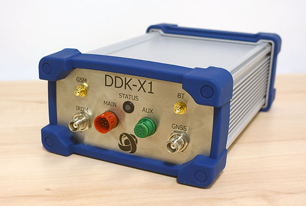
DDK Positioning’s precise GNSS positioning solution provides an accuracy of less than 5 cm
NSSLGlobal has entered a strategic alliance with DDK Positioning, to incorporate enhanced GNSS positioning navigation and timing solutions into NSSLGlobal’s maritime portfolio.
NSSLGlobal will now provide, install and service DDK’s GNSS precise point positioning (PPP) solution which enhances the ability of NSSLGlobal’s customers to precisely locate and track their assets.
DDK’s independent GNSS technology is provided exclusively through Iridium’s global satellite constellation, and creates a robust, resilient and completely independent GNSS solution that has an enhanced accuracy of less than 5 cm, compared to the standard GPS accuracy of 10 m.
“This partnership is a fantastic fit for DDK Positioning,” said Kevin Gaffney, DDK Positioning CEO. “We are now in a place to provide our clients with our precise positioning solutions globally and we are delighted to formalize our working relationship with NSSLGlobal with the signing of this new strategic alliance.
Photo: DDK Positioning
“To continue the journey with such a strong and well-respected company such as NSSLGlobal, and with their reach in the market, makes great sense and we are looking forward to the journey that we will have together.”
“DDK Positioning is leading the field in advanced GNSS positioning,” said Paul Rutherford, service director, NSSLGlobal. “We’re pleased to partner with such an innovative company and to be able to add this technology offering on top of the already extensive navigation and communication portfolio we offer our customers. The system will provide greater location accuracy, along with the ability to help detect and mitigate spoofing.”
The European GNSS Agency (GSA), with the European Commission, has published an information note on the Galileo High Accuracy Service (HAS). The 16-page document provides an overview of the main characteristics of the service, information on features such as service levels, target performance, an implementation roadmap, and an overview of the target markets for the service.
Target markets for Galileo HAS include geomatics, precision agriculture, consumer solutions and the space sector.
The market for high-accuracy positioning is dynamic, driven by various factors, including
emerging applications such as autonomous vehicles and drones;
technological advances such as dual-frequency chipsets for the mass-market; and
the market situation, with cheap or free-of-charge augmentation services available in some countries.
These factors are resulting in the democratization of high accuracy, which is becoming a more widespread commodity, rather than the exclusive domain of professional applications.
With the Galileo HAS, Galileo will pioneer a worldwide, free high-accuracy positioning service aimed at applications that require higher performance than that offered by the Galileo Open Service.
Benefitting several markets
Target markets for the HAS include geomatics, agriculture or consumer solutions. Transport is also a major potential target market, with possible applications in aviation, road, rail and maritime and inland waterways.
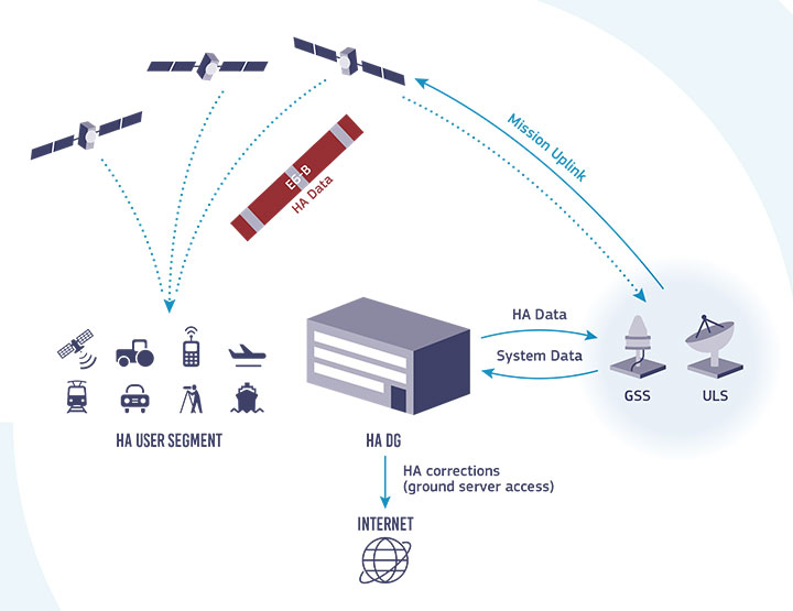
In these markets, the HAS will provide high-accuracy precise point positioning corrections for Galileo and GPS free of charge, in the Galileo E6-B data component and by terrestrial means, to achieve real-time improved user positioning performances, with a positioning error of less than two decimetres in nominal conditions.
“With its High Accuracy Service, Galileo will be the first satellite constellation able to provide a high-accuracy precise point positioning service globally, directly through the Signal in Space,” said GSA Executive Director Rodrigo da Costa. “This will be another key differentiator of the Galileo system, giving it a competitive advantage over other systems and allowing it to foster innovation in both consolidated and emerging markets.”
Galileo HAS high-level architecture. (Image: GSA)
HAS Initial Service
HAS Phase 1 will cover the provision of an initial Galileo HAS resulting from the implementation of a high-accuracy data-generation system that processes Galileo data only.
Phase 2 will see full provision of the Galileo HAS, meeting its target performance of 20-cm worldwide positioning accuracy after 2024.
Through the HAS, Galileo will offer a unique service with the transmission of corrections directly via Galileo satellites, allowing free high-accuracy positioning globally, for everyone.
Every month, we ask members of our Editorial Advisory Board to weigh in on a topic. For the January 2021 issue, we asked,
Will precise point positioning (PPP) replace real-time kinematic (RTK)? If so, for which applications and when?
Miguel Amor
“Recently, Hexagon’s Autonomy & Positioning division demonstrated RTK levels of performance — globally —through PPP technology; we call it RTK From the Sky (see page 29). I believe that PPP adoption rates will grow significantly in the coming years and eventually replace RTK — especially in areas that are not well served by RTK networks or similar services. Adoption rates will depend on which applications can field GNSS receivers capable of the signals and constellations to perform like RTK.”
Miguel Amor Hexagon’s Autonomy & Positioning division
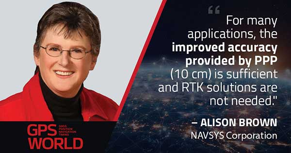
Alison Brown
“For many applications, the improved accuracy provided by PPP (10 cm) is sufficient and RTK solutions are not needed. However, the typical convergence time of PPP is between 20 and 40 minutes, depending on the number of satellites available, satellite geometry, the quality of the correction products, the receiver’s multipath environment, and atmospheric conditions. This slow convergence compared to RTK solutions will limit application for many real-time applications such as mobile solutions.”
Alison Brown NAVSYS Corporation
Jean-Marie Sleewaegen
“PPP-RTK combines near-RTK accuracy and quick initialization times with the broadcast nature of PPP, over internet or L-band. PPP-RTK can be seamlessly integrated into GNSS receivers, bringing convenient sub-decimeter accuracy to applications where configuring RTK is not practical or where there is no internet connection. PPP-RTK is likely to be adopted by emerging mass-market applications such as UAVs, while RTK will probably remain prevalent in applications where it is already well established, such as precision agriculture.”
Jean-Marie Sleewaegen Septentrio
Bernard Gruber
“I do not believe that PPP will replace RTK technology solutions anytime soon. Satellite-based GNSS correction services with an emphasis on global provide worldwide access, but achieving the required accuracy, due to convergence, can be slow. Today, myriad users and emerging customers may utilize corrections augmented with RTK transmitter/base stations that hybrid solutions can provide, thus solving both the age-old navigation issue of obscuration and near real-time positioning simultaneously.”
For the past decade, widespread deployment of autonomous vehicles (AV) has been just over the horizon — that imaginary line that recedes as you approach it.
It has been delayed mainly by technical issues, which will eventually be followed by legal and regulatory ones, mainly regarding liability, and by a struggle to gain public acceptance. When they finally reach the mass market, however, AVs will reduce traffic fatalities by at least an order of magnitude because they do not get distracted, drunk, drowsy or enraged and are much better able than humans to gauge distances and speeds.
Additionally, they will be able to communicate with each other and with the infrastructure, which will not only further improve safety but also reduce congestion and fuel consumption via the adoption of techniques such as convoying.
Logically, even if AVs only somewhat reduced traffic fatalities (about 38,000 per year in the United States), the public should welcome them with open arms. In reality, though, the reaction to even a single death caused by an AV — like the one in Tempe, Arizona, in March 2018 — can set AV deployment back years.
Therefore, car manufacturers are challenged to develop AVs that can navigate extremely safely in a wide range of traffic, road and weather conditions. For more than a century, human drivers have routinely managed sudden obstructions, poor visibility and dangerous behavior by other drivers that still bedevil their new robotic counterparts, despite the sensors, microprocessors and algorithms at their disposal.
The primary technological obstacle to widespread deployment of AVs on roads is “the complexity of the system and the amount of time that it takes to develop a functionally safe autonomous vehicle,” said Steve Ruff, general manager of Trimble’s On-Road Autonomy Division, which develops positioning solutions for autonomous vehicles that operate on public roadways. He cites the time required to develop “a comprehensive, safe, autonomous vehicle technology stack” and points out that “we are on the verge of going from level two to level three, which requires the driver to stay engaged in the driving experience in case the autonomous system has a problem.”
Multiple sensors
While AV developers are exploring different ways of obtaining reliable sub-centimeter positioning accuracy, all generally rely on collecting data from multiple sensors on the vehicle and applying an algorithm to synthesize the data in real time and generate a continuous, accurate position. Computer vision, radar and lidar play important roles in an AV by perceiving its surroundings and localizing it to an a priori map. This functions well in feature-rich urban environments, but can degrade in sparse highway settings.
Radar has good ranging accuracy, but is unable to detect and recognize traffic signs and road markings. Lidar has even greater ranging accuracy but is challenged in featureless areas, such as straight highways and country roads. Digital cameras are good for detecting objects and navigating in tunnels and urban canyons, but, like lidar, are less effective on featureless roads and in low visibility conditions (rain, fog, darkness, snow, sun glare).
Plus, they are challenged by the absence of road markings or the presence of construction. Inertial navigation systems (INS), while excellent at compensating for brief GNSS outages, can only guide vehicles for short stretches due to their inherent drift. (INS are essential on aircraft and vessels, whose attitude is constantly changing, but that is not relevant for vehicles, which travel essentially flat relative to, and at a constant distance from, the road surface.)
GNSS and Corrections
Satellite navigation plays a central role in an AV. At a minimum, it guides it from a trip’s origin to its destination, including stops or waypoints in between, the same way it would advise a human driver. It also continuously alerts the vehicle to upcoming stops, slowdowns, turns, congestion and other challenges that are already mapped—whether long in advance by map makers or moments earlier via crowdsourced updates. Finally, if sufficiently accurate, it can steer the vehicle to keep it in the center of its lane and to make smooth lane changes and turns. Determining on which road a vehicle is requires an accuracy of less than 5 meters; determining in which lane it is requires an accuracy of less than 1 meter; and determining where in the lane it is requires an accuracy of less than 0.5 meters.
Two kinds of GNSS corrections are commonly used for AVs: real-time kinematic (RTK) and precise point positioning (PPP). RTK, which is generally accurate to the centimeter level, relies on ground-based reference stations at fixed, surveyed locations that process and transmit error-corrected signals to receivers within a 10- to 20-kilometer range, typically in real-time via a cellular link. PPP, which is accurate to the tens of centimeters, uses a global network of ground stations to generate an accurate signal, and transmits it to subscribers via the internet or geostationary satellites. However, the receiver in the vehicle needs 20 to 60 minutes to align with the PPP signal before it can rely on it.
Both RTK and PPP are established in industries such as mining, construction and precision agriculture, where vehicles operate in controlled environments with little or no traffic. AVs on public roads present a far greater challenge. A car’s typical range far exceeds that of any RTK base station, and base stations can also have down time, while in-vehicle systems must use multi-frequency receivers to reduce the convergence time of the PPP signal. In case of outage of either the GNSS signal or the correction signal, the vehicle’s system must rely on data from its other sensors and recover swiftly from the error state.
Trimble’s RTX is road ready
The first PPP service in commercial use for passenger vehicles is Trimble’s RTX, which provides real-time, centimeter-level positions via IP/cellular connection or satellite broadcast worldwide. It delivers positioning via satellite to GM’s Super Cruise, a hands-free driver assistance feature for use on limited access freeways.
“We’re GNSS receiver-agnostic,” said Steve Ruff of Trimble’s On-Road Autonomy Division. “We’ll use any receiver that’s preferred by the OEM building the AV.”
Image: Trimble
Trimble, he recalled, became GNSS agnostic with regard to automotive navigation nearly 15 years ago, when it decided to get out of the commercial-grade or consumer-grade GNSS business. “It has worked out quite well, because not only can we meet the quality costs and performance targets of our OEM customers, it also allows us to do what we’re good at. We can take our positioning solution, adapt it to work with any measurement engine, and put together a solution that fits the OEM’s requirements just right.”
Automotive companies, Ruff explained, generally have certain requirements for the GNSS receiver, including certain standards for application-specific integrated circuits (ASIC) and automotive safety integrity level (ASIL), as well as meeting their accuracy requirements. “So, if the receiver has suitable code and carrier phase measurements that can support their accuracy level, then that will be the third requirement for the receiver for the automotive segment.”
For off-road vehicles for agriculture, construction and mining, Trimble only uses its own receivers, said Thomas Utzmeier, general manager of the company’s Off-Road Autonomy Division. Their requirements center on precision, position availability in challenging environments, and integrity of the position. “In the use cases on which we are working,” Utzmeier said, “we certainly see sub-decimeter accuracy. We are targeting probably three, four, sometimes five centimeters.” In more challenging use cases, GNSS plus sensor fusion — including INS and optical data — maximizes position availability and accuracy, he explained.
For the on-road segment, Ruff’s division offers a “positioning stack” that includes corrections, the GNSS position algorithm and inertial fusion. “Then we provide services to help the OEMs take our software and integrate it on the platform of their choice.”
New service provides PPP convergence for centimeter-level accuracy on land, air and marine applications around the world
Research from Hexagon’s Autonomy & Positioning division has resulted in breakthrough innovations in precise point positioning (PPP) that enable nearly instant global centimeter-level accuracy. These developments pave the way to bring “RTK from the Sky” performance to worldwide users through correction service products and GNSS receivers from Hexagon.
RTK from the Sky technology provides the quick accuracy of an RTK solution with the high accessibility and availability of PPP. Users will no longer have geographic or regional infrastructure restrictions — they will be free to operate anywhere around the world with the same premium level of positioning performance.
RTK from the Sky technology removes the traditional PPP barrier of long convergence times as well as internet and radio communication limitations, delivering instantaneous convergence anywhere in the world. This breakthrough establishes the foundation for assured positioning with no downtime in marine, agriculture, and autonomous applications.
To achieve these results, there must be masterful attention to detail throughout the entire positioning ecosystem: no errors conveniently cancelled and no errors ignored. All errors are carefully estimated and removed from the final GNSS position faster and more reliably than ever before.
This end-to-end fine-tuning of measurement quality and error mitigation establishes the foundation for RTK from the Sky performance. No matter the location or application, users will be able to rely upon the highest availability and accuracy of corrections anywhere in the world, without the convergence time, Hexagon said.
“In 2020, PPP has become RTK — without the mobility limitations,” said Sandy Kennedy, VP of Innovation at Hexagon’s Autonomy & Positioning division. “RTK from the Sky has been a very satisfying development. To see this kind of positioning performance available anywhere in the world is the realization of the next step of innovation for GNSS.”
RTK from the Sky technology will be the foundation for future correction service products and applications from Hexagon built for diverse applications.
As the skipper of Galileo 4, a 50-foot sailboat on the Columbia River, I instruct my crew to alert me if the water under the keel drops below 10 feet and take immediate action if it drops below 5 feet, because I cannot constantly monitor my chart to avoid running aground. Yet, the huge cargo ships that navigate the river for 100 miles from its mouth at Astoria to the Port of Portland sometimes have as little as two feet of vertical clearance.
This feat of navigation is made possible by the knowledge, experience and electronic equipment used by the river pilots who steer the ships, the hydrographers who survey the river, and the dredge operators who perform the Sisyphean task of maintaining the required depth of the navigation channel. Each additional inch of draft they enable allows a ship to carry additional cargo worth up to several million dollars.
In similar ways, marine professionals around the world cooperate to chart ocean bottoms and to keep ports, harbors and navigable waterways safe for the more than 90% of trade that is carried by ships. Additionally, off-shore installations—such as fiber optic cables, pipelines, drilling platforms and wind turbines—all require accurate surveys of the ocean floor. Finally, population growth in coastal areas and sea level rise due to climate change are driving the need for bathymetric data for planning and emergency management.
Bathymetry
For centuries, mariners recorded water depth using nothing more than a lead line, a compass, a sextant and a rudimentary nautical chart. This was such a time-consuming process, however, that they could only perform it for a tiny percentage of the world’s oceans and coastlines. Today’s technology makes the process not only more accurate, but also vastly more efficient.
In deep waters, depth data is collected using huge multi-beam echo sounders (MBES) that operate at very low frequencies. As the depth decreases, smaller devices are used that operate at higher frequencies and, therefore, have higher resolution. However, close to shore, the efficiency of these devices drops dramatically, as the cone of their sound signal is cut off by the slope of the shelf. This is where airborne lidar sensors become a much more efficient means of collecting depth data.
In addition to data from the sounders, bathymetry requires data about the vessel’s location and attitude. The former, an obvious requirement for any kind of mapping, are collected by differential GNSS receivers. The latter, collected by an inertial measurement unit (IMU), are used to compensate for variations in the depth measurement depending on the vessel’s rotational movements (roll, pitch and yaw) and translational movements (heave, surge and sway). This is the same reason that aerial photogrammetrists use IMUs on aircraft.
Challenges
Traditionally, MBES systems have been large, complex and expensive. However, they are rapidly becoming smaller, cheaper, quicker to deploy, and easier to use thanks in part to the introduction of inertial systems that use microelectromechanical systems (MEMS), said Ludovic Bazin, technical support manager for SBG Systems, which specializes in MEMS technology. “You can see that the new systems are being increasingly deployed in smaller autonomous vehicles, on smaller autonomous surface vessels (ASV), and even smaller vessels. So, people can go quickly in operation,” he said. An additional advantage, he pointed out, is that they do not require an export license.
A key to accurate bathymetric surveys is reducing the error budget aboard the vessel, where the survey positions are tied back to a GNSS antenna. “You have errors all the way through the system,” said Richard Turner, vice president of global marine sales for Hexagon’s Autonomy & Positioning division, which caters mostly to the market for survey related to oil and gas. He attributes the largest improvements in recent years to the increase in accuracy using precise point positioning (PPP). “If you are out of range of real-time kinematic (RTK) and any other near-shore positioning, the accuracy of PPP is constantly improving,” he said. “It is getting down into the five-centimeter range horizontal or better than that.”
Turner also pointed to the tight integration of inertial navigation system (INS) technology with other systems. “Every time you improve the accuracy of your system the specs go up,” he said. Therefore, the challenge is to ensure that the equipment is installed properly, which requires very accurate offset measurements. “It is no good having two centimeters position accuracy if your heading or your offsets are wrong.” Generally, he points out, boats are not designed for this type of installation, due to such things as long cable runs.
Hexagon will send surveyors out with equipment from Leica, one of its divisions, to do the dimensional control and to calibrate the gyroscopes, which are another source of error. In 2014, Hexagon acquired Veripos. “Many of the people in the Veripos organization come from the offshore survey world or the dredging world, so it is very marine focused,” said Turner. “No other providers have the marine experience that we do.”
For bathymetric software companies, the main current challenge is “keeping up with all the modern and cheaper hardware,” including RTK receivers, echo sounders, and side scan sonars, said Leon Steijger, owner and programmer at Eye4Software B.V., which makes the Hydromagic software.
Requirements and capabilities
To get accurate data, all position and depth records must be timestamped with high precision so that the location of the echo sounder pings can be calculated during post-processing, Steijger noted. “The software needs to be able to generate elevation maps, depth contours, and 3D terrain views and must support volume calculations to calculate how much water there is in a basin, or to determine how much material has been removed during dredging operations.”
Hydromagic uses “plugins,” which are pieces of software that are loaded optionally to interface sensors with the software. “For some hardware we also offer a plugin containing a user interface that can be used to, for instance, upload a planned route to an automatic pilot or to control the signal processing parameters of an echo sounder.” Operators only need to specify the dimensions of their vessel and correct for the sound velocity and the static draft (the distance between the water surface and transducer). They see the vessel’s track in real time, but the rest of the data are post-processed.
Hexagon controls its own correction services and the network that delivers them. “We obviously build our own GPS receivers, so we can tightly integrate inertial systems,” said Turner. “We use third-party inertial systems. However, because we have access to the tracking loops on the GNSS boards, we can tightly integrate that inertial system so it gives a level of coupling that’s difficult unless you are actually building those boards yourself.” While near-shore operations can use RTK or post-processing, he pointed out, “the offshore guys often use real-time positioning to collect data for oil and gas. And that is really where we come to the party, because we have all those services too.”
SBG Systems designs, manufactures, and calibrates its own IMUs, then integrates them with GNSS boards, creating OEM products. “We also design and produce our own firmware algorithms to merge all those datasets,” said Bazin. “From the selection of the MEMS sensor to the final product, SBG will design, manufacture, develop, and produce the entire systems. We also provide tools for people to integrate our systems to develop their own libraries or to integrate our libraries into their systems and work with some integrators for APIs so they can control our systems from their own application.” The company’s post-processing system, Qinertia, integrates GNSS corrections with raw IMU data. “So, when we do post-processing, we reprocess an entire solution at the end for position, but also for stabilization for pitch, roll and heading,” Bazin explained. One of the benefits is the ability to remove many multipath effects.
For bathymetric surveys using an unmanned aerial vehicle (UAV), the control software must keep the platform at a constant altitude and speed over the surface of the water, because the echo sounder is dragged through the water at the end of a cable, explained Alexey Dobrovolsky, CTO of SPH Engineering, based in Riga, Latvia, which delivers UAV-related software. Therefore, he said, “missions should be executed in a fully automated mode.” His company’s software only requires the UAV’s operator to define the survey area, set the direction of the survey lines, and specify the distance between them. The software will handle everything else. “We automatically recalculate the depth measured from the echo sounder to the real depth in our data files using data from a radar altimeter,” he said. “Our software contains a high-end model of the echo sounder, which has a tilt sensor and a pitch sensor.”
Of course, dragging an echo sounder from a UAV only works for small areas, such as in open pit mines where the liquid can be very contaminated. “The flight time with an echo sounder of the most popular UAV will be around 20 minutes,” said Dobrovolsky. “That determines the maximum length of the survey lines that can be covered by a single flight.”
A couple of years ago, SPH began to provide some UAV-based bathymetry solutions that use low frequency ground-penetrating radar (GPR). There are two scenarios when GPR can be useful for bathymetry, Dobrovolsky explained. The first one is to do bathymetry through ice on the surface of lakes or rivers, which would require drilling holes to use an echo sounder. “With GPR, you can do bathymetry through the ice layer,” he said. The second scenario is mountain rivers with extremely strong currents, when it is not possible to use a standard manned or unmanned boat, because GPR works without contact with the water.
Bathymetric systems are now also deployed on autonomous underwater vehicles (AUVs) that are only one to three feet long. “MEMS INS are compact and can be integrated directly with MBES systems, which provide an all-in-one compact system that can be easily deployed and operated because they are lightweight and their mechanical alignments are known and fixed,” said Bazin. “Some of these systems can go 2,000 meters below the surface of the water.” In post-processing, he pointed out, some MEMS INS can have an angular accuracy as low as 0.07 degrees for the vessel’s pitch and roll and a heading accuracy of as little as 0.01 degrees.
Outputs
To integrate diverse sensors with a UAV, SPH developed an onboard computer, called UgCS SkyHub, that logs data from the sensors. In the case of the echo sounder, it can be an NMEA stream or just a stream of current depth measurements, said Dobrovolsky. The device is also connected to the UAV’s autopilot, so it logs the platform’s position and speed, and with the altimeter. UgCS SkyHub can record three types of data files: a CSV file containing the coordinates, depths, and a few additional parameters; a file in NMEA 0183 format, which is also standard for bathymetry; and a SEG-Y file containing the full echo sounder data, including, for example, sediments and objects in the water.
SBG Systems’ software has two kinds of outputs, Bazin explained. First, a proprietary binary format, as well as NMEA and ASCII formats, that are used to provide stabilization and navigation for the platform in real-time. Second, a standard as-built survey format for post-processing. “Then, we have very powerful tools to output ASCII files that are completely configurable from header to footer,” he added.
Eye4Software’s main outputs are volume reports or plot sheets for end customers containing a map with depth colors and depth contours, as well as cross section views or XYZ export files for further processing in, for instance, AutoDesk Civil 3D and AutoCAD.
Feature image: A UAV from SPH Engineering tows a bathymetric sonar just under the surface of a river. (Photo: SPH Engineering)
Thirty years ago, more than a decade before most people had even heard of GPS, receiver manufacturers and surveyors were already improving on it by providing and using correction services to compensate for errors in the system—including clock drift, orbit errors, signal errors, atmospheric errors and multipath.
Today, dozens of public and commercial correction services enable users to achieve accuracies of decimeters, centimeters or even millimeters. Also, many GNSS processing services correct measurements taken in the field using data from reference points. Increasing positioning accuracy has become the cornerstone of modern GNSS practice.
The current boom for correction services is driven mostly by the demand for high accuracy from the automotive industry (including the development of self-driving cars), as well as smart consumer devices and various forms of automation. Automotive companies and telecoms are deploying infrastructure around the globe to provide centimeter-level positioning. GNSS satellites also can transmit corrections directly, as the Japanese CLAS service from the QZSS constellation does, and Galileo’s High-Accuracy Service (HAS) soon will. To compensate for receiver-side issues — multipath, jamming and spoofing — some GNSS receivers also incorporate advanced positioning algorithms.
Clock and orbit errors are specific to each satellite; they do not depend on the position of the receiver. But atmospheric errors are introduced when the signal travels from the satellites to the user. Reference stations (base stations) of GNSS receivers installed at fixed and precisely surveyed positions provide corrections that compensate for both sets of errors to the rovers carried by field crews. When connected, reference receivers spread over a geographic area form reference networks, such as that of continuously operating reference stations (CORS). Achieving maximum accuracy requires initializing the receiver, which can take a few seconds to several minutes, depending on the type of corrections.
Established and new methods
Two established methods have been used for decades.
Real-time kinematic (RTK). In RTK, a receiver obtains correction data from a single base station or a local reference network in the same area.
Precise point positioning (PPP). While accessible from anywhere in the world, receiver initialization for PPP can take up to 30 minutes. Also, a few PPP correction services only provide corrections for satellite clock and orbit errors and not for atmospheric errors, limiting users to a lower accuracy level than with RTK.
Hybrid PPP-RTK. In recent years, new methods have emerged. Hybrid PPP-RTK combines near-RTK accuracy and quick initialization times with the global access of PPP. It relies on a network of reference stations within about 150 kilometers of each other. The stations collect GNSS data and calculate both satellite and atmospheric correction models. The network then broadcasts these corrections via internet, satellites or cellphone towers to subscribers, who can use them to achieve sub-decimeter accuracy.
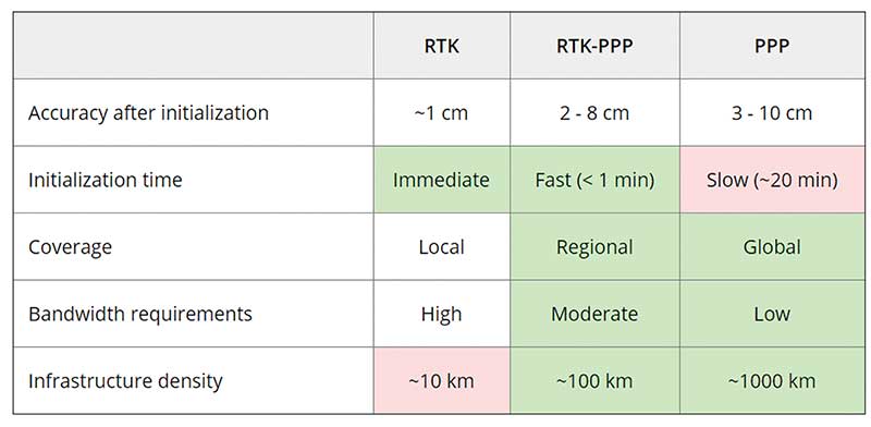
Each of these methods has advantages and disadvantages (see table 1). RTK, which relies on communication between the user and the local correction service, provides centimeter accuracy over small areas. PPP-RTK and PPP broadcast corrections and require a lighter infrastructure, making them scalable for mass-market and industrial applications. The new services are cheaper and more user-friendly than traditional correction services.
TABLE 1: Differences of various correction methods. (Chart: Septentrio)
CORS/VRS
Traditional reference networks — often called CORS or virtual reference station (VRS) networks — have long been a source of differential GPS (DGPS) and RTK corrections, mainly for surveying and mapping applications, which require high accuracies.
“Most CORS in the United States are strictly for providing high-accuracy correction data to GNSS users who need to know their position to less than an inch,” said Alex Ngu, applications engineer at Trimble. “However, some — like Utah’s TurnGPS network and the North Carolina Geodetic Survey (NCGS) — have considered dabbling in using them to double up for weather monitoring.” In some regions, such as Japan and Washington state, CORS are also used to study plate tectonics and provide early warning of earthquakes.
CORS receivers often operate in remote locations and may be powered by solar panels. Therefore, they require low power consumption and the ability to configure, run and update remotely. They also need to archive on-board measurements and withstand harsh environments.
Changes in the market
As the market for GNSS corrections changes, so does the role of CORS networks. They are increasingly used for industrial automation that needs centimeter accuracy, including construction and agriculture. “Now, due to the growth in autonomous systems, such as autonomous cars, people are looking at corrections in a completely different way and with more focus on mass markets,” said Gustavo Lopez, market access manager at Septentrio. Septentrio lets customers choose which correction service to use.
“CORS/VRS networks will keep focus on performance and on adding constellations and signals, but nothing major is expected to happen in these traditional systems,” Lopez said. They will continue to exist because they focus on centimeter-level accuracy for survey, construction, mining, machine control and precision agriculture. “What will really change the market are these new services with 10-cm to 20-cm accuracies, which also offer a new way of delivering the data, namely broadcasting rather than using two-way communication methods.” This helps with adoption by emerging applications, Lopez said.
He predicts that applications needing 10- to 50-centimeter acurcy will migrate to cheaper services, including new consumer applications, advanced driver-assistance systems (ADAS), professional applications such as robotics, UAVs, logistics and internet of things (IoT) applications.
Mobile technologies adopting dual-frequency chipsets also will need correction services. “We will see more and more telecoms interested in providing GNSS corrections as a service, as is already the case in Asia and Europe,” Lopez said. “A few CORS/VRS networks will try to capture part of this emerging applications market by reusing their technology or partnering with other companies to provide a more transparent solution.”
One might think that the rapid expansion of the market for corrections would make it possible for traditional CORS networks to make 1-cm accuracy available at a much lower price. The roadblock is high infrastructure costs, Lopez explained. CORS/VRS networks are expensive to maintain because they require a high density of stations. New services that use broadcasting technology and PPP-RTK positioning modes rely on less dense networks.
New uses for old CORS
A key benefit of a VRS is that performing RTK positioning across the area it covers does not require guarding a separate GPS base station. Using VRS, the CORS network acts essentially as a continuous reference station within the entire network, enabling RTK positioning using a single rover in the field.
Randy Osborne, VRS network manager at Louisiana State University’s Center for GeoInformatics, reports a growth in new applications beyond surveyors. VRS expanded to precision agriculture, and then into applications such as lidar and UAVs. “We are also seeing strange applications that we never thought of. For example, plumbing companies use it to navigate underground from a truck that has a position on the network, and then they vector from the truck underground into pipelines,” Osborne said. Subscribers also include companies performing survey work for fracking and petrochemical projects.
OSR vs. SSR
Most GNSS correction services are based either on the observation state representation (OSR) or on a state space representation (SSR) of the errors. OSR and SSR use different techniques, delivery mechanisms and core technologies.
OSR. Legacy GNSS correction service providers supply OSR correction services; examples are RTK and networked RTK (RTN). They rely on transferring corrected GNSS observations from the nearest reference station to the rover using a standardized format. They focus on a geographic region and target surveying, machine control and precision agriculture, providing centimeter-level accuracy up to about 30 kilometers of the nearest reference station. Because these services require bi-directional communications and large bandwidth, it is hard to ramp them up for mass-market applications.
SSR. By contrast, new players in the market for correction services, as well as some of the larger legacy ones, provide SSR correction services. SSR uses a network of reference stations to model major errors over large areas. They then transfer this model to the rovers, which create local error models and apply them to their GNSS observations. Depending on the service, accuracy ranges from less than 5 cm to 20 cm, convergence times from 10 seconds to 30 minutes, and coverage from continental to global. Because SSR corrections are broadcast, they can be more easily distributed through internet connections and L-band satellite channels. Because all the rovers rely on the same stream of GNSS correction data, SSR services work well for mass-market applications. The growth in SSR technology is driven mainly by the needs of the automotive industry but is sufficiently generic for adoption in other markets.
The challenge of vertical accuracy
A CORS receiver stands atop the Old River Auxiliary Control Structure, a floodgate system in a branch of the Mississippi in central Louisiana. (Photo: Trimble)
While OSR and SSR have comparable accuracies on a horizontal plane, they differ greatly in their vertical accuracy and initialization times, Osborne said. “When we look at CORS for active control and positioning in the National Spatial Reference System, we are mainly trying to get a handle on the vertical part, as it is the hard problem to solve,” he said.
High-precision vertical accuracy is a challenge for any GNSS-based method. Conventional surveying is still the gold standard. With differential leveling, like with digital levels, results in millimeters are possible. Post-processed GNSS, using data from a good geometry of CORS or base data, can yield results under 2 cm vertical, as can real-time OSR methods like RTK and RTN. SSR solutions, like PPP and hybrids, are presently achieving 5 cm at best. An Achilles heel for SSR vertical solutions is the lack of data for localized sources of error, like tropospheric conditions. Semi-dense networks of CORS can feed ionospheric data to speed PPP convergence, but not the level of tropospheric data needed to match the vertical results that OSR and conventional methods can.
Trimble
Trimble GNSS base-station receivers have been used for 40 years on every continent, according to the company. Today, products in use as CORS stations typically are Alloys, NetR9s and NetR5s. The company operates more than 300 networks worldwide, incorporating more than 5,000 CORS receivers.
Trimble offers a full spectrum of solutions, services and subscriptions related to CORS networks. They range from supplying CORS software, hardware and services, to providing network management services to run a secondary backup system for a network, or even operating a network on behalf of its owner. For those who just want a high-accuracy correction to support their surveying, GIS or machine guidance and control work, “Trimble operates one of the largest CORS networks in the world to which users can subscribe — Trimble VRS Now, Trimble RTX and OmniSTAR services,” Ngu said.
Feature photo:
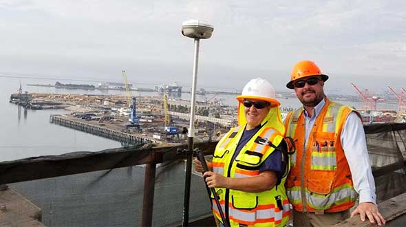
In Long Beach, California, correction services support the 250-foot-high Gerald Desmond Bridge project. Trevor Rice (left), president of D. Woolley & Associates, joins Kimberley Holtz, director of survey, Port of Long Beach. (Photo: Trimble)
By R. Eric Phelts, Kazuma Gunning, Juan Blanch and Todd Walter
Innovation Insights with Richard Langley
AS WE NOTED IN THE LAST INNOVATION COLUMN, integrity — at least from a safety viewpoint — is the most important characteristic of a navigation system. Yes, accuracy, availability and continuity are also required but, without integrity, the advertised accuracy of a system might become meaningless and perhaps misleading. While GPS and user receivers are highly reliable, we cannot presume that there will never be an erroneous signal transmitted by a GPS satellite that would result in a receiver outputting a hazardously misleading position solution. While “supervisory” systems such as satellite-based augmentation systems monitor GPS signals and can alert users about defective satellites within a very short period of time, it is advantageous for a user receiver to autonomously detect problematic satellites and quarantine them so that they do not perturb the position solution.
It is for this reason that receiver autonomous integrity monitoring (RAIM) techniques were developed. As we know, a receiver needs signals from a minimum of four satellites simultaneously to determine its 3D position and its clock offset. However, typically there are more than four satellites in view, and so multiple solutions using subsets of four satellites are possible. If five satellites are visible, then it is possible to determine that one of them is faulty, but not which one (geometry plays a role here). This is called fault detection (FD). And if six satellites are visible, the faulty satellite can be determined and then excluded from the position solution (fault detection and exclusion, or FDE). This is the basic principle of RAIM.
Advanced RAIM (ARAIM) extends RAIM to other constellations beyond GPS. ARAIM enables the use of the newer GNSS constellations to provide better levels of performance than RAIM with GPS alone. It also uses dual-frequency measurements for enhanced vertical positioning reliability.
Central to positioning techniques providing a safety-of-life service is the notion that the uncertainty of a provided position must be conservatively estimated and provide for both nominal uncertainty and the uncertainty of a faulted solution such as that detected using RAIM. These conservative estimates are known as the horizontal and vertical protection levels. The horizontal protection level (HPL) is the radius of a circle in the horizontal plane with its center at the true position, which describes the region that is assured to contain or bound the provided horizontal position to a very high probability. The vertical protection level is half the length of a segment in the vertical direction with its center at the true position, which describes the region that is assured to contain or bound the provided vertical position to a very high probability. The probability levels are typically taken to be 99.9999998 and 99.99999% for HPL and VPL, respectively.
The usual approach for RAIM and ARAIM is to use the so-called “snapshot” approach, where measurements are assumed to be uncorrelated epoch to epoch. In this month’s column, a team of authors from Stanford University discusses a superior approach for ARAIM using the technique of precise point positioning.
Advanced Receiver Autonomous Integrity Monitoring (ARAIM) is implemented using solution separation in positioning and navigation software. Solution separation computations presume one or more GNSS satellites may be faulty, and they iteratively compute multiple position solutions comprised of subsets of the n satellites in view (n, n-1, n-2, and so on) to ensure that at least one of the solutions is fault-free. Using assumptions on the nominal and faulted uncertainty of the solutions, the software can compute conservative horizontal and vertical protection levels (PLs) by bounding the uncertainty from all the solutions. This assures (to a targeted level of probability) that the user position is contained within these limits.
Traditional solution separation techniques generally operate as a “snapshot.” The basic measurements are dual-frequency, carrier-smoothed pseudorange (code), and errors are generally assumed to be uncorrelated from epoch to epoch. This procedure requires that errors at each time step are conservatively bounded with large uncertainties (sigmas) designed to protect the user against the worst-case error. These assumptions minimize the complexity and computational cost of the solution by providing a robust, provably safe bound. However, the PLs computed are relatively large. In addition, they can change suddenly from one epoch to the next due to changes in available satellites or platform dynamics. This can make meeting performance goals (such as continuity) for aircraft approaches more challenging.
Solution separation procedures using techniques based on precise point positioning (PPP) implement an extended Kalman filter (EKF) to filter measurements over time. In this case, the basic measurements are dual-frequency code and carrier phase, and errors are assumed to have some correlation between each time step to the next. Accordingly, these techniques leverage higher quality measurements (that is, carrier-phase-based as opposed to code-based) to smooth and reduce large sigmas and to estimate (and calibrate) errors over time. The complexity associated with defining and characterizing the decorrelation models for the errors, so that the nominal covariance produced by the EKF conservatively describes the actual error, is significant. Also, the computational cost of estimating the error states may be substantially higher than with the traditional snapshot approach. However, the computed protection levels provide integrity and are often significantly smaller. In addition, the filtering makes them more robust to platform dynamics, which makes them well-suited for aircraft in flight.
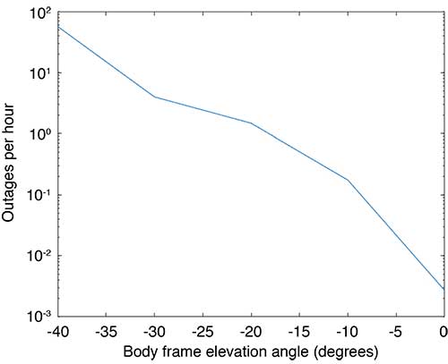
Flight Data: Outages and Cycle Slips. ARAIM performance may be significantly affected by aircraft dynamics. Specifically, banking can induce satellite outages and cycle slips. Outages weaken the constellation geometry and can cause sudden changes in the protection level. Frequent cycle slips prevent code measurements from being smoothed, potentially inflating protection levels of carrier-phase-smoothed code measurements for extended periods of time.
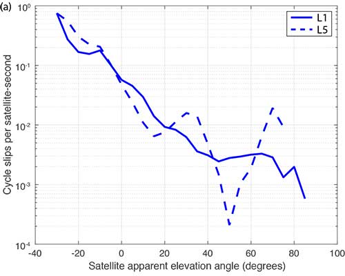
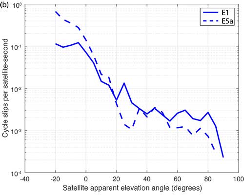
When the outages and cycle slips are computed as a rate, a trend can be seen. Both increase notably as the relative elevation angle to the satellites decrease. FIGURE 1 shows an example of outages as a function of the apparent elevation angle of the satellites (relative to the aircraft). Cycle slips on GPS L1-L5 and Galileo El-E5a are plotted in FIGURES 2 (a) and (b), respectively.
FIGURE 1. Outages as a function of body frame or apparent elevation angle during aircraft banking. (Image: Authors)FIGURE 2a. Cycle-slip rate (per satellite-second) for GPS L1-L5. (Image: Authors)FIGURE 2b. Cycle-slip rate (per satellite-second) for E1-E5a. (Image: Authors)
For this article, we have used the flight data from one of our earlier papers on the effect of aircraft banking on ARAIM performance (see Further Reading). With this data, we show that significant advantages of PPP can be retained even during aircraft maneuvers when outages and cycle slips threaten ARAIM continuity and availability the most.
MODEL ASSUMPTIONS
The traditional snapshot solution separation approach is well-established and was implemented according to the standards established by a working group operating under the U.S.-European Union Agreement on GPS-Galileo Cooperation, which has been extended to all constellations (see Further Reading). For this article, we limited the constellations to GPS and Galileo, and the prior probabilities assumed for satellite and constellation faults were as follows:
Psat = 10-5, Pconst,GPS = 10-8 and Pconst,GAL = 10-4
We implemented the PPP algorithm with solution separation using an EKF using dual-frequency code and carrier-phase measurements (from GPS and Galileo) with estimated parameters comprising the receiver position and velocity, clock biases for each constellation in use, a residual tropospheric delay, carrier-phase float ambiguities for each tracked carrier, multipath error, receiver differential code bias, and broadcast orbit and clock error. Modeled (not estimated) effects include solid Earth tide modeling, ocean loading, an initial tropospheric delay and relativistic effects. Many of the details of the implementation can be found in our paper “Design and Evaluation of Integrity Algorithms for PPP in Kinematic Applications” (see Further Reading).
PPP techniques typically utilize precise ephemeris information obtained from a global network of ground reference stations such as those operating in the network coordinated by the International GNSS Service. Snapshot solution separation techniques, however, use only ephemeris information broadcast from the satellites themselves. For a proper comparison of the protection levels computed by each technique, the PPP filter was constrained to use this broadcast information.
The model we have applied is mostly typical of a traditional PPP implementation with one significant exception — the state tracking the error contribution of the broadcast orbit and clock on each line-of-sight signal. The error contributed by the broadcast orbit and clock is handled by the filter leveraging a characterization of the rate of change of the error, then including it as an estimation state for each line of sight and only adding enough process noise to capture the slowly changing error. We have previously characterized the rate of change of the error in the broadcast orbit and clock and process noise (for GPS). Complete tables of initial state uncertainties and additional settings for process and measurement noise were provided in our earlier work (see Further Reading).
RESULTS
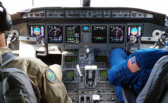
Flight data collected over a period of approximately one year was used to evaluate ARAIM performance through momentary outages and cycle slips due to aircraft dynamics. A multi-constellation, multi-frequency receiver tracked GPS (L1 C/A and L5) and Galileo (E1 and E5a) satellites. This receiver is installed in a Global 5000 jet owned and operated by the FAA William J. Hughes Technical Center. It records and stores GNSS measurements whenever flights are taken. The data we used for this article included data recorded over approximately 35 flights from September 2017 to April 2018.
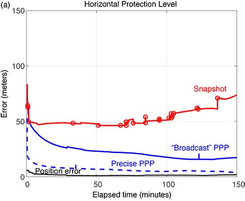
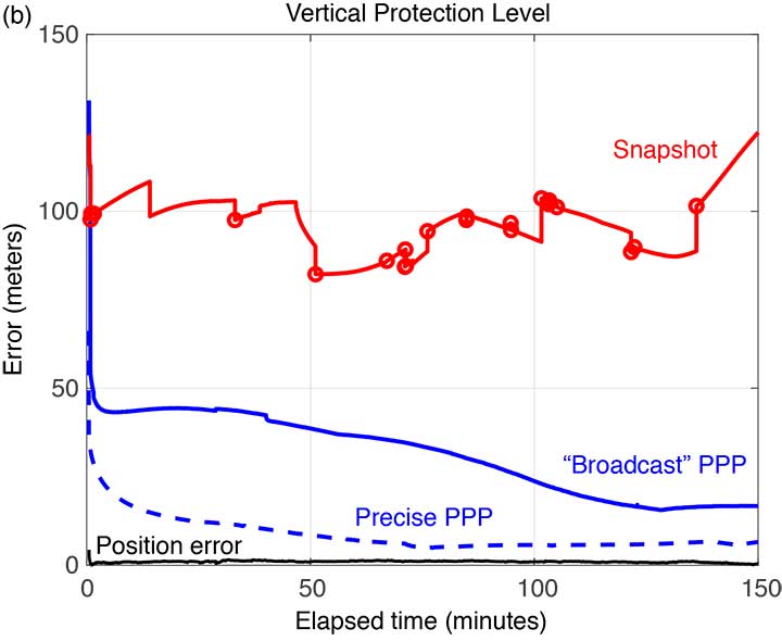
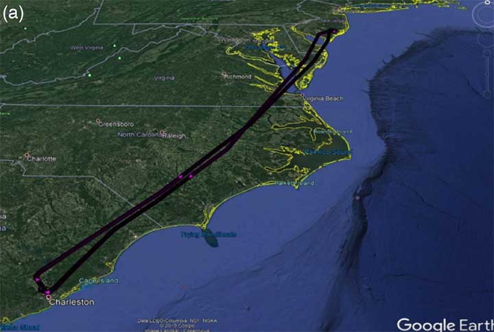
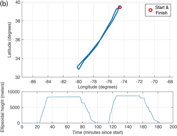
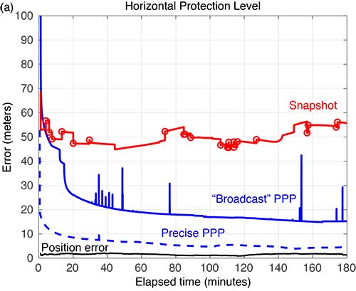
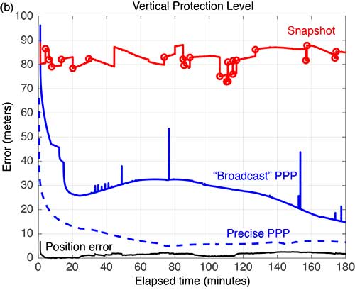
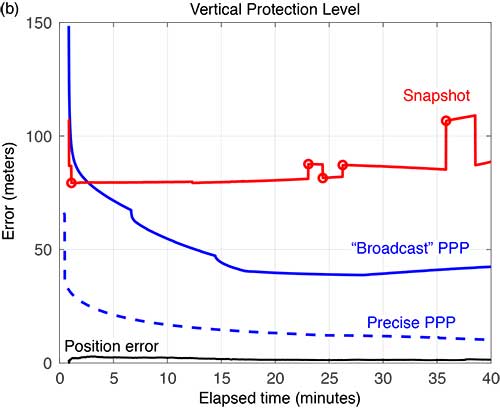
FIGURE 3 shows the trajectory and altitude information corresponding to a single flight (Flight #6) taken on Sept. 20, 2017, and FIGURE 4 compares the corresponding horizontal and vertical protection levels computed using snapshot and “broadcast” PPP techniques. For an additional reference, we also computed protection levels using PPP with precise orbits and clocks (we call this precise PPP despite the terminology redundancy) and plotted these in Figure 4, too.
FIGURE 3b. Altitude information for Flight #6 (Sept. 20, 2017). (Image: Authors)FIGURE 4a. Horizontal protection levels for Flight #6 (Sept. 20, 2017); red circles indicate a satellite being dropped or reentering the solution. (Image: Authors)FIGURE 4b. Vertical protection levels for Flight #6 (Sept. 20, 2017); red circles indicate a satellite being dropped or reentering the solution. (Image: Authors)
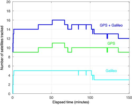
Several things are readily apparent from these comparisons. First, after the initial time required for convergence, there is a substantial reduction in the PLs using the broadcast-PPP-based approach. The precise PPP PLs, as expected, produce the largest reduction, but use additional information not available to the snapshot method. In addition, the snapshot solution separation PLs vary significantly due to cycle slips and momentary satellite outages. FIGURE 5 shows the number of satellites tracked by the receiver during this flight; red circles plotted on the snapshot protection-level line indicate when satellites are coming into and out of view. Despite numerous abrupt changes in number of measurements and measurement quality, the EKF of the PPP techniques produces PLs that are relatively smooth and continuous.
FIGURE 5. Number of satellites tracked for Flight #6 (Sept. 20, 2017). (Image: Authors)
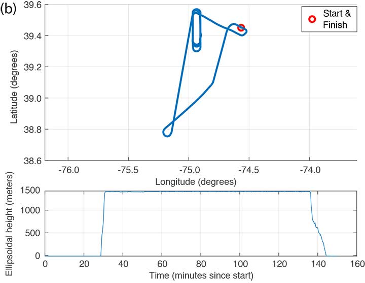
FIGURE 6 shows the trajectory and altitude information corresponding to Flight #4 taken on Sept. 15, 2017.
FIGURE 6a. Flight path for Flight #4 (Sept. 20, 2017). (Image: Authors)FIGURE 6b. Altitude information for Flight #4 (Sept. 20, 2017). (Image: Authors)
FIGURE 7 compares the horizontal and vertical PLs for snapshot solution separation and the PPP-based techniques.
FIGURE 7. Horizontal protection levels for Flight #4 (Sept. 15, 2017); red circles indicate a satellite being dropped or reentering the solution. (Image: Authors)FIGURE 7b. Vertical protection levels for Flight #4 (Sept. 15, 2017); red circles indicate a satellite being dropped or reentering the solution.
As in the case shown in Figure 4, the PLs in Figure 7 reveal a substantial reduction in the mean PLs computed using the PPP-based approach. And the snapshot solution separation approach displays even more variations due to momentary satellite outages. Some of the cycle slips affected enough satellites to introduce brief spikes in the PPP solution as well. These reconverge quickly, but they suggest that some tuning of the EKF can still be done to mitigate these interruptions. Still, the filtered approach produces PLs that are more robust to the outages and are substantially smaller than with the snapshot method.
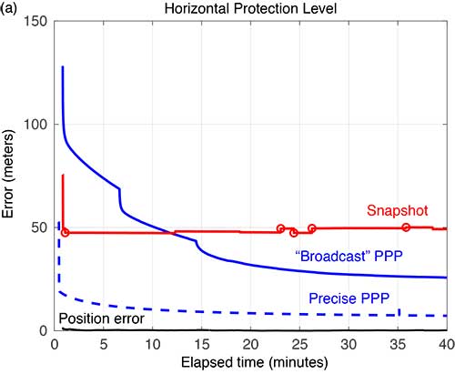
FIGURE 8 compares the horizontal and vertical PLs computed using snapshot solution separation and PPP techniques for Flight #20 — where the airplane remained stationary on the runway. In the absence of flight dynamics, the levels for all the approaches were relatively smooth. However, a few discontinuities can still be observed for the snapshot case. Also note, in the case of the broadcast PPP, the convergence time is noticeably longer. This is likely because the integer ambiguity resolution in the solution took longer to converge without platform motion.
FIGURE 8a. Horizonta protection levels for a stationary aircraft (Flight #20, Dec. 4, 2017); red circles indicate a satellite being dropped or reentering the solution. (Image: Authors)FIGURE 8b. Vertical protection levels for a stationary aircraft (Flight #20, Dec. 4, 2017); red circles indicate a satellite being dropped or reentering the solution. (Image: Authors)
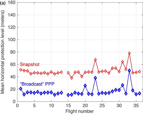
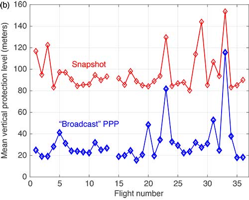
The mean horizontal and vertical PLs for both techniques are summarized in FIGURE 9. (There were issues with the data from Flight #14 and it was not processed.) The PPP approach consistently produces protection levels anywhere from 30 to 75% smaller than those computed using the snapshot approach. The mean PLs for the PPP techniques were always below those computed with the snapshot method.
FIGURE 9a. Comparison of mean horizontal PLs for “snapshot” vs. a PPP-based technique. (Image: Authors)FIGURE 9b. Comparison of mean vertical PLs for “snapshot” vs. a PPP-based technique. (Image: Authors)
CONCLUSIONS
Data from 35 flights was used to compare ARAIM protection levels computed by the traditional “snapshot” solution separation versus a PPP-based approach during both in-flight and several static scenarios. We observed that the filtering of PPP methods yields mean PLs approximately 30 to 75% of those computed using traditional methods in all cases. This improvement can be attributed to exploiting — through filtering and estimation — carrier-phase-based measurements and a time-correlation of the errors. In addition, the EKF employed by the PPP approach demonstrated improved robustness to outages and cycle slips induced by aircraft dynamics. Despite the increased complexity and computational cost, we believe that PPP approaches hold promise for significantly improving ARAIM performance.
ACKNOWLEDGMENT
This article is based on the paper “Evaluating the Application of PPP Techniques to ARAIM Using Flight Data” presented at ION ITM 2020, the 2020 International Technical Meeting of The Institute of Navigation, San Diego, California, Jan. 21–25, 2020.
MANUFACTURER
The flight data was recorded using a Trimble BX935-INS receiver fed by an Antcom Avionic II GNSS antenna.
R. ERIC PHELTS is a research associate in the Department of Aeronautics and Astronautics at Stanford University, California. He received a Ph.D. in mechanical engineering from Stanford University in 2001. His research involves signal deformation monitoring for SBAS and flight-data analyses for ARAIM.
KAZUMA (KAZ) GUNNING is a Ph.D. candidate in the GPS Laboratory at Stanford University working under the guidance of Todd Walter. He is also the navigation algorithms and architecture lead at Xona Space Systems in San Mateo, California. His research interests are in precise point positioning and integrity.
JUAN BLANCH is a senior research engineer at Stanford University, where he works on integrity monitoring algorithms for radionavigation. He received a Ph.D. in aeronautics and astronautics from Stanford University in 2003. He has received The Institute of Navigation (ION) Parkinson and Early Achievement awards.
TODD WALTER is a research professor in the Department of Aeronautics and Astronautics at Stanford University. He received his Ph.D. in applied physics from Stanford University in 1993. His research focuses on implementing high-integrity air navigation systems. He has received the ION Thurlow and Johannes Kepler awards. Walter is also a Fellow of the ION and has served as its president.
“A Baseline RAIM Scheme and a Note on the Equivalence of Three RAIM Methods” by R.G. Brown in Navigation, Vol. 39, No. 3, Fall 1992, pp. 301–316.
Advanced Receiver Autonomous Integrity Monitoring
“SBAS Corrections for PPP Integrity with Solution Separation” by K. Gunning, J. Blanch and T. in Proceedings of ITM 2019, the 2019 International Technical Meeting of The Institute of Navigation, Reston, Virginia, Jan. 28–31, 2019, pp. 707–719.
“Design and Evaluation of Integrity Algorithms for PPP in Kinematic Applications” by K. Gunning, J. Blanch, T. Walter, L. de Groot and L. Norman in Proceedings of ION GNSS+ 2018, the 31st International Technical Meeting of the Satellite Division of The Institute of Navigation, Miami, Florida, Sept. 24–28, 2018, pp. 1910–1939.
“Effect of Aircraft Banking on ARAIM Performance” by R.E. Phelts, J. Blanch, K. Gunning, T. Walter and P. Enge in Proceedings of ION GNSS+ 2018, the 31st International Technical Meeting of the Satellite Division of The Institute of Navigation, Miami, Florida, Sept. 24–28, 2018, pp. 2632–2641.
“Precise Point Positioning” by J. Kouba, F. Lahaye and P. Tétreault, Chapter 25 in Springer Handbook of Global Navigation Satellite Systems, edited by P.J.G. Teunissen and O. Montenbruck, published by Springer International Publishing AG, Cham, Switzerland, 2017.
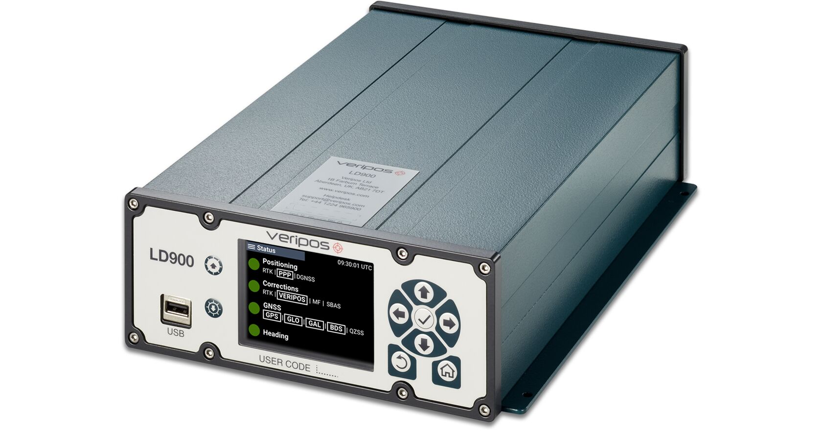
Veripos has released the LD900, a quad-band GNSS receiver capable of tracking GPS, GLONASS, BeiDou, Galileo and QZSS constellations to provide reliable and accurate positioning. Access to multiple GNSS signals allow for better satellite availability and reduce the impact of satellite masking or blockage, which can affect positioning.
LD900 also receives L-band signals on multiple channels, providing access to the worldwide independent correction links and services provided by Veripos. With correction data available simultaneously from up to three correction satellites, the impact of satellite masking can be minimized to ensure reliable reception of correction data. Using the independent L-band RF input on the LD900 allows the connection of a dedicated L-band antenna ensuring optimal reception of correction services, especially at high latitudes, the company said.
Veripos provides accurate and reliable positioning for all marine applications via their redundant positioning and multi-frequency precise point positioning (PPP) Apex and Ultra services.
The Apex5 correction service utilizes all GNSS constellations delivering 5cm positioning accuracy for use in the most demanding offshore applications. Real-time kinematic (RTK) corrections can be utilized by the LD900 for applications where this service is required.
The intuitive color display and navigation menu makes setup, configuration and system status monitoring simple. The display also helps troubleshoot issues with the LD900 allowing faults to be quickly diagnosed and resolved. The LD900 can also be configured remotely through the Veripos Quantum software.
Features and Benefits
Supports decimeter-level multi-constellation positioning with Veripos Apex and Ultra PPP correction services
Multi-channel L-band allows simultaneous tracking of 3 Veripos correction service satellites
Independent L-band RF input
Easy-to-use, intuitive, color display for simple configuration and monitoring
Advanced signal filtering mitigates the effects of interference from other transmitters
Optional ALIGN GNSS heading solution
Optional MSK Beacon receives corrections from IALA marine radio beacon network
Automatic 72-hour rolling data log for incident support
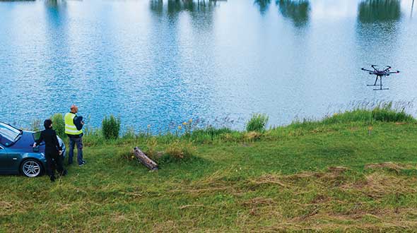
Why do we keep hearing about unmanned aircraft all the time, almost everywhere? Fortunately, the buzz has gone beyond next-door neighbors flying dangerously close to your roof or hovering annoyingly around a living room window, and incidents of UAV incursions shutting down airports seem to be getting fewer — improved enforcement and higher penalties may be slowing down these incidents.
Now, UAV users are taking on productive, innovative tasks that couldn’t previously be done, or finishing projects surprisingly quickly and more affordably than ever before, with drones built or adapted for new applications. And equipment manufacturers are creating new sensors customized for use on drones.
Commercial, integrated GNSS/inertial sensors are available that have extremely high performance — previously only available with expensive mil-spec electronics — but in lightweight, small packages, supported by real-time kinematic (RTK), precise point positioning (PPP) corrections or post-processed kinematic (PPK). UAVs carry still, video and multi-spectral cameras generating automatically geocoded outputs, ready for post processing into multi-layered formats — virtually everything a customer could ever dream of having. And lidar sensors enable drones to build accurate models of everything they overfly.
Drones originated largely with military forces. Originally used for forward intelligence gathering, UAV tasks have multiplied and substantially expanded in scope.
Commercial industries were quick to realize the benefits. Before drones, the cost of many tasks done manually would be prohibitive and too time-intensive. Fast, affordable data collection now allows us to quickly tackle and solve many problems.
UAVs can pre-survey large, previously inaccessible tracts of difficult terrain, collect detailed visual representations of entire cities, monitor and support crop growth, or even survey underwater terrain using lidar. UAVs provide crop-growing support by flying autonomous patterns and spraying fields with pesticides or fertilizer. They also are being called into service to spray villages with disinfectant to control the spread of coronavirus, and to survey England’s beaches to monitor coastal erosion.