Orolia, through its Spectracom brand, has introduced built-in scenarios for testing eCall In Vehicle Systems compliance to the GNSS requirements of the regulation as an option with its latest Spectracom GSG simulator products.
In an initiative to bring life-saving rapid assistance to motorists involved in a collision, European Union (EU) regulation 2015/758 requires new vehicle types of M1 and N1 anywhere in the EU to be equipped with eCall in-vehicle systems as of March 31, 2018.
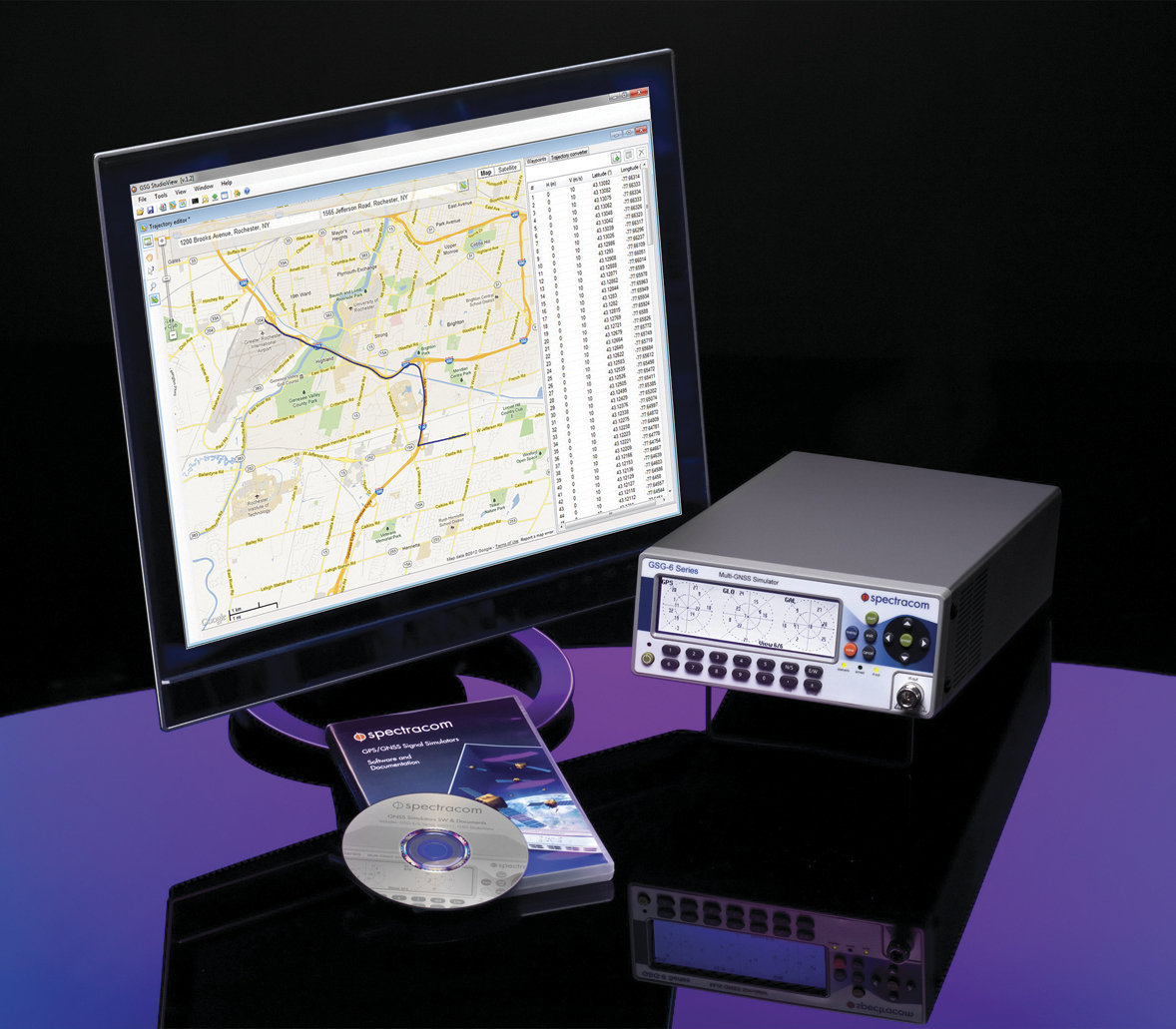
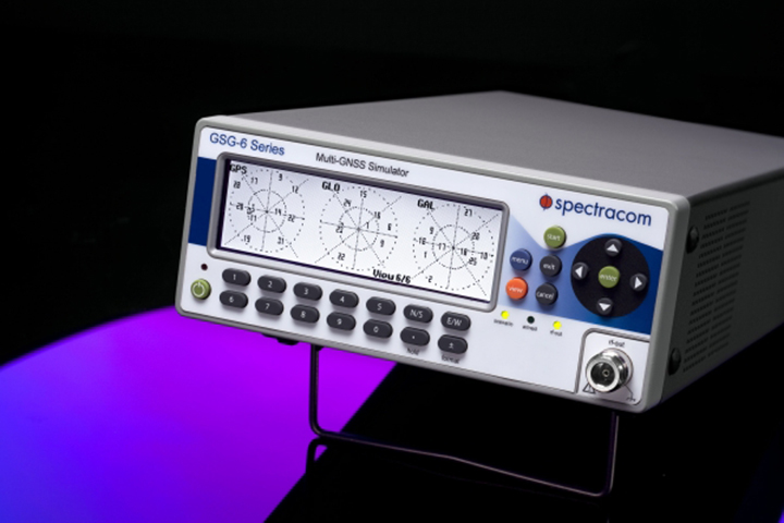
Spectracom’s GSG-6 Simulator with monitor.
In case of a crash, eCall systems automatically call the nearest emergency centre while sending the exact location, dramatically reducing response times. EU member states that do not comply will be refused EC type-approval for new types of motor vehicles.
Spectracom is providing options to ensure that automotive manufacturers who plan to continue selling into this market are equipped with the right tools for testing the eCall regulatory compliance of their equipment.
The Spectracom GSG line of GNSS simulators efficiently simulate all the major GNSS constellations needed for testing compliance of critical signal receiving equipment in a variety of eCall scenarios including:
Positioning accuracy under different conditions
Time-to-first-fix
GNSS receiver sensitivity
Re-acquisition performance following signal outages
Playing specific static and dynamic trajectory scenarios
Changing RF transmit power level manually or remotely sequenced as required by standard
“The eCall regulations require significant effort on the part of the auto industry to comply, and we are pleased to be including standard eCall scenarios as an option for our popular line of Spectracom GSG simulators,” said Lisa Perdue, GSG product manager at Spectracom. “We work in partnership with our automotive industry clients and will continue evolving the simulation product line to meet their needs for compliance testing with life-saving regulations.”
Working with the Radio Technical Committee for Maritime Services (RTCM), Spirent has created test scenarios that simulate realistic satellite reception conditions at sea so that GPS distress beacon performance can be improved, allowing users to be rescued faster by search and rescue organizations.
One of the first customers to use these scenarios to test its locator beacons is ACR Electronics Inc., a manufacturer of emergency lifesaving equipment. Its latest ACR and ARTEX products have been tested using a Spirent signal simulator, and have been certified as meeting the RTCM standards for cold-start time-to-first-fix, which specifies the time taken by a device when it is turned on to capture GPS signals and determine its location.
Photo: Spirent
The U.S. Federal Communications Commission (FCC) has now mandated that in future, any new products in the related categories must be tested using a GNSS simulator and the scenarios in the RTCM standards, which were developed by Spirent.
“We are able to test the performance of our dual-frequency GPS/Galileo receivers using a Spirent simulator that can accurately simulate signals from different constellations to enhance the performance of our Emergency Position Indicating Radio beacons (EPIRBs, PLBs and ELTs),” said Bill Cox, Director of Engineering at ACR. “Our customers will soon be able to take advantage of a new confirmation system that will let them know that their call for help was heard.”
“We are very pleased to have worked with RTCM and ACR to improve maritime safety”, said Martin Foulger, General Manager of Spirent’s Positioning Business Unit. “This project shows the importance of testing in realistic conditions to give better end-user experience, which in this case could be a matter of life or death. This will make lifesaving equipment more reliable both for maritime users and search and rescue agencies.”
Photo: Spirent
The RCTM discovered that Cospas-Sarsat 406MHz beacons with integral GPS receivers suffered from poor cold start performance, causing delays in providing accurate location information to Search and Rescue (SAR) authorities. It later discovered that this was because beacons tended to be tested on land in benign conditions, rather than in real-world oceanic conditions.
It has addressed the issue by specifying a set of performance standards for Emergency Position Indicating Beacons (EPIRBs), Personal Locator Beacons (PLBs), Hand-held VHF Radios with integral GPS Receivers, Manoverboard (MOB) devices and Satellite Emergency Notification Devices (SENDs).
Spirent was asked to develop a set of custom test scenarios that enable manufacturers to simulate realistic satellite reception conditions at sea in laboratory environments. Use of these scenarios enables manufacturers to better assess the performance of their products in the real world.
Details of the FCC mandate can be found in the Federal Register, Vol. 81, No. 241, Dec. 15, 2016, Page 90739, FCC 47 CFR Parts 1, 25, 80 and 95.
LabSat has launched the LabSat 3 Wideband simulator, which can simultaneously record multiple signals from different constellations.
Small, battery powered and with a removable solid-state disk, LabSat 3 Wideband allows users to quickly gather detailed, real-world satellite data and replay those signals on the bench.
Photo: LabSat
With three channels, a bandwidth of up to 56 MHz and 6-bit sampling, LabSat 3 Wideband can handle almost any combination of constellation and signal that exists today, with plenty of spare capacity for future planned signals.
For example, users can now record GPS L1, L2 and L5 at the same time as GLONASS G1 and G2 and BeiDou B1 and B2.
An interactive bandwidth calculator allows users to see which combinations of constellation and signal can be recorded. Users can also change the bandwidth and bit depth to see how it affects the selection available.
Despite the huge capability of the unit, the LabSat 3 Wideband remains easy to use, retaining the one-touch recording and playback feature.
A removable battery pack gives two hours of use, and the 1-TB solid-state disk drive can be swapped in seconds.
Specifications
Recording bandwidth: 10MHz, 30MHz or 56MHz
Recording resolution: 2, 4 or 6 bits (depending on bandwidth)
Simulate signals from all GNSS and regional navigation
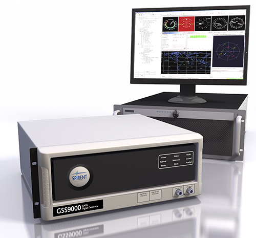
Spirent’s GSS9000 constellation simulator.
The Spirent GSS9000 Multi-Frequency, Multi-GNSS RF Constellation Simulator can simulate signals from all GNSS and regional navigation. It offers a four-fold increase in RF signal iteration rate (SIR) over Spirent’s GSS8000 simulator.
The GSS9000 SIR is 1000 Hz (1 ms), enabling higher dynamic simulations with more accuracy and fidelity. It includes support for restricted and classified signals from the GPS and Galileo systems, as well as advanced capabilities for ultra-high dynamics. It can evaluate resilience of navigation systems to interference and spoofing attacks, and has the flexibility to reconfigure constellations, channels, and frequencies between test runs or test cases.
Hardware changes can be made in the field, supported by the new on-board calibrator module. The GSS9000 is extensible and can support the widest range of carriers, ranging codes, and data streams for the Galileo, GPS, GLONASS and BeiDou systems, as well as regional/augmentation systems. Multi-antenna/multi-vehicle simulation for differential-GNSS and attitude determination, and interference/jamming and spoofing testing are also supported.
GSS9000 Attributes
1000-Hz simulation iteration rate (SIR) and hardware update rate (HUR) enabling real-time remote control and trajectory delivery with extremely low latency and simulation of ultra-high dynamic motion
160 channels plus 640 embedded multipath channels across 10 independent frequencies in one chassis
Single RF version and dual RF version for differential GNSS and multi-vehicle simulation
0.3 mm RMS pseudorange accuracy, 120,000 m/s relative velocity
Highly flexible configurations selectable via a “cabinet” of license keys
Complete portability of Spirent SimGEN scenarios
In-field upgradeability
Future-proofed for all advances in GNSS technology
Spirent Communications plc is releasing a new series of multi-frequency, multi-GNSS RF constellation simulators. The GSS7000 series provides an entry to multi-frequency testing, with a modular approach to enable this new precision GNSS simulation system to expand with users’ needs.
The GSS7000 system will suit receiver, system and application developers who want to take advantage of new satellite navigation systems and the better accuracy offered by civilian, multi-frequency GNSS.
“Testing across multiple GNSS systems requires more channels and more frequencies with accurate modeling across multiple constellations,” said Stuart Smith, lead product manager for Spirent’s Positioning business unit. “The GSS7000 is a new type of simulator in terms of capability and flexibility. We have gone above and beyond traditional thinking to create a new system for a new era of GNSS test.”
Spirent Communications’ GSS7000 series of multi-frequency GNSS simulators provides a modular approach to testing.
The GSS7000 series offers faithful emulation of all civil GNSS systems and regional augmentation systems, and allows devices to be tested under a multitude of operating environments and error conditions, the company said. The GSS7000 has the flexibility to reconfigure satellite constellations, channels and frequencies between test runs or test cases. Four software control variants are offered.
For existing Spirent customers, the GSS7000 has been designed to be backward compatible, enabling the re-use of existing test cases. It allows full in-field upgradeability to add constellations, channels, and other options such as interference generation and sensor simulation.
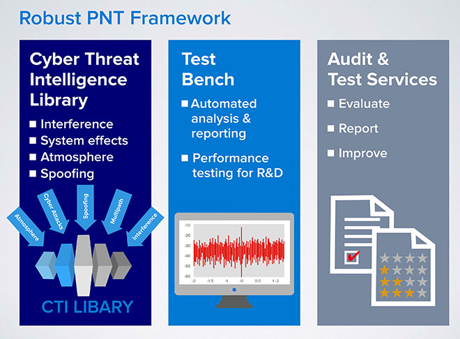
Spirent Communications has announced a Robust PNT Test Framework that evaluates GPS and GNSS security vulnerabilities for positioning, navigation and timing (PNT) systems.
Threats to GNSS and related PNT applications are more orchestrated and coordinated, with the motivation to disrupt or cause financial loss. The technology to disrupt GPS has also become much more accessible, resulting in GPS vulnerability gaining attention at hacker conventions.
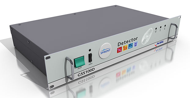
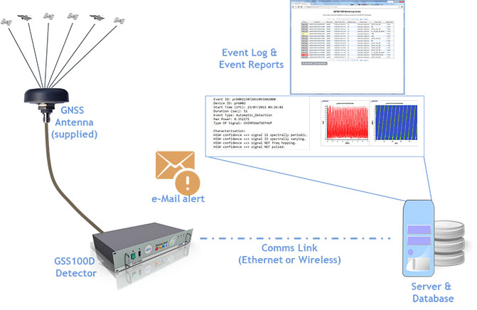
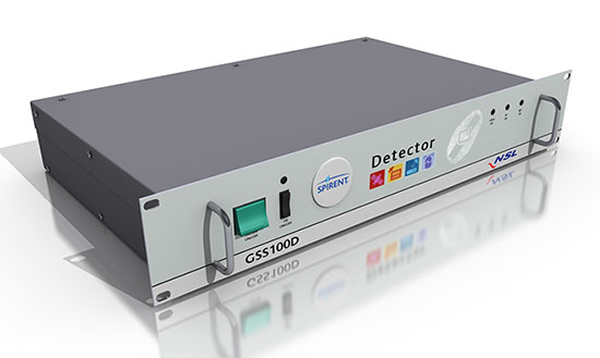
Spirent’s GSS100D Detector, developed in collaboration with Nottingham Scientific Ltd, enables detection, characterization and analysis of real GNSS threats.
The Robust PNT Test Framework will be used by technology, system and application developers where PNT is critical. Spirent’s framework enables threats to be detected in the field, taken into the lab and re-synthesized along with GPS and other GNSS signals. In addition, Spirent’s threat intelligence library of actual and typical threats provides a wide range of GNSS segment errors and spoofing attacks, as well as space weather and other vulnerabilities for preventive troubleshooting.
“Spirent wants to move beyond talking about the increase of GNSS vulnerabilities and offer a pragmatic approach to enable informed decision making when it comes to evaluating the impact of vulnerabilities,” said John Pottle, marketing director of Spirent’s Positioning Technology Division. “Through our Robust PNT Test Framework Spirent is pulling everything together to enable users to readily audit systems and take practical steps to improve resilience.”
Spirent Federal Systems will demonstrate its GSS9790 simulator at ION GNSS+, taking place Sept. 14-17 in Tampa, Fla.
The Spirent demonstration “Interference and Anti-jam Antenna Testing Using the Spirent Wavefront Simulator (GSS9790)” will take place in Room 17 on Thursday, Sept. 17, 2-2:45 p.m. Attendance gains one ticket for an Apple Watch raffle, with the winner to be announced Thursday at 4 p.m., Booth C in the Exhibit Hall.
The ability of a CRPA to null out unwanted signals while still allowing wanted signals to be received is key to its performance. This ability allows GNSS receivers to continue to operate in challenging signal environments, Spirent said in an email. The similar but slightly different signal composition at each antenna element allows the CRPA to distinguish direction for wanted and unwanted signals. Recreating this signal environment in an anechoic chamber is critical in allowing the discerning test professional to rigorously evaluate the performance of a CRPA system.
The Spirent GSS9790 is designed for this testing. The 9790 allows for code, carrier and amplitude control on a satellite-by-satellite and interferer-by-interferer basis.
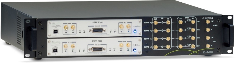
Averna has launched an RF tool offering high-performance record-and-playback and real-time simulation in one platform.
The Averna RP-6100 series is a self-contained, record-and-playback solution for RF application validation. It can capture all GNSS bands, as well as HD Radio, Wi-Fi, LTE, radar, and cognitive radio — plus impairments — to significantly advance RF projects and harden product designs. The RP-6100 series features up to four channels, 160 MHz of recording bandwidth, tight channel synchronization, an extended frequency range of 10 MHz to 6 GHz, and 14-bit resolution.
The RP-6100 can also be equipped with Skydel Solutions’ software-defined, real-time GNSS simulator, which delivers easy setups, integrated maps, dynamic scenario creation, high precision and tight parameter controls to enable highly repeatable simulations of current and future GNSS conditions, as well as corner cases.
Features include:
Frequency range of 10–6000 MHz, covering all GNSS bands, plus HD Radio, WiFi, LTE, and more
Multi-channel (1-4): Up to 160 MHz of bandwidth at 14-bit resolution (< 1 Hz)
3.8 TB SSD storage or 16 TB HDD storage (for up to 22 hours of recordings)
Preloaded with RF Studio software for quick setups and in-depth analysis
Four models: RP-6120 (2 ch.), RP-6120P (2 ch. portable), RP-6120D (2 ch. desktop) and RP-6140 (4 ch.)
Optional real-time Skydel GNSS Simulator for complete GNSS corner-case/testing scenarios
“We are very excited to partner with Skydel Solutions as a way to continue to provide our customers with the latest technologies and products,” said Benoit Richard, VP of Innovation & Strategy at Averna. “Their technology maps perfectly with our portfolio of RF instrumentation solutions, which empower device manufacturers to efficiently generate, record, simulate, analyze, and play back all common radio, video, and navigation signals, ensuring complete test coverage and the highest quality for their RF products.”
“Today, Skydel is proud to introduce its software-defined GNSS Simulator, running in real-time Ettus and NI USRP hardware,” said Stéphane Hamel, co-founder and CEO of Skydel Solutions. “We are also very pleased to announce that our GNSS Simulator can be combined with Averna’s RP-6100 Series. These technologies complement each other perfectly, making the combined solution the ideal platform for high-performance design validation of RF and GNSS devices.”
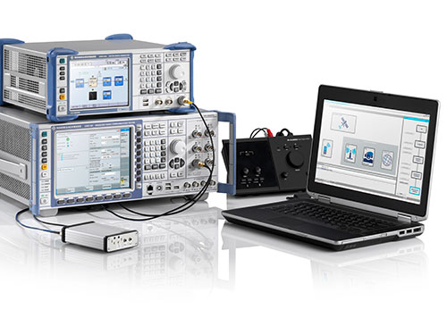
The Rohde & Schwarz CMW500 is being used to test the ERA-GLONASS system.
The Certification Center Svyaz-Certificate in Russia is now using the R&S CMW500 to certify ERA-GLONASS systems in line with the TR CU 018/2011 technical guideline. The independent Russian test lab is currently the only test lab in Russia accredited to certify these systems. The R&S CMW500 is a wideband radio communication tester.
Equipped with the R&S CMW-KA095 application software, the R&S CMW500 meets all requirements for testing ERA-GLONASS systems and provides reliable, reproducible tests in line with the Russian GOST R 55530 specification, Rohde & Scwarz said. In addition, the R&S CMWrun sequencer software (R&S CMW-KT110) makes the test solution fully automated and user-friendly.
Effective January 1, 2015, all new car models introduced to the Russian market must be equipped with an automatic ERA-GLONASS emergency call system.
Spectracom’s GSG-6 Series multi-frequency GNSS signal simulator. Photo: Spectracom
Spectracom has added capability to simulate India’s global navigation satellite system, IRNSS, and Japan’s regional satellite system, QZSS, to its GSG-6 Series multi-frequency GNSS signal simulator. The simulator is designed to be field upgradeable to simulate all current and future GNSS constellations so current customers can benefit from these features without the need for a factory return in most cases.
“Spectracom understands the need for system developers and integrators to be compatible with various GNSS systems. Support for multiple constellations is a requirement in many markets and additional satellites add signal diversity for improved reliability,” said Spectracom Global Sales and Marketing Vice President Rohit Braggs. “Our easy-to-use, compact and affordable GNSS simulator can now be configured with IRNSS and QZSS capability in addition to the big four: GPS, GLONASS, BeiDou and Galileo. Our customers can buy what they need now and easily upgrade in the future, often times without a hardware upgrade.”
In anticipation of the deployment of new GNSS systems, Spectracom ensures that every GSG simulator that leaves the factory is tested for compliance with all L-band signal frequency and modulation specifications as defined in their ICDs, the company said.
The Series 6 multi-frequency simulator is fully capable of all four bands of any system: L1 / E1 / B1; L2 / L2C; L5 / E5 / B2; and E6 / B3.
“As we have seen with our recent roll-out of Beidou and Galileo signal compatibility, when the need for new signals arise, we will offer those capabilities with a simple upgrade path,” Braggs said. “This ensures our customer’s investment is always protected.”
Spirent Communications has added capabilities to its ultra-wideband GSS6425, which enable recording up to 150MHz bandwidth of GNSS signals. Users can now record up to three RF frequency bands at any one time with 10-, 30- or 50-MHz bandwidth each. Other enhancements include the ability to record up to four video streams, USB 3.0 support and easy remote-control using tablet or smartphone.
A single portable test system, the ultra-wideband GSS6425 allows customers to record GPS L1 and L2 and GLONASS L1 and L2 signals commonly needed for applications requiring very high accuracy such as surveying, precision agriculture, automotive research, and advanced navigation.
“Customers undertaking field testing are increasingly looking for portable and easy to use test solutions,” said Rahul Gupta, commercial segment lead for Spirent’s positioning division. “With these new abilities they can now easily configure, monitor, and control the GSS6425 using their mobile phone or tablet over Wi-Fi.”
Recording of four video streams by attaching webcams allows the user to capture visual records of any location. This enables users to fully understand the conditions at the time of recording, not only inside the vehicle (including activity on the dashboard, facial expressions, navigation unit, and more) but also outside the vehicle (such as top, front and back scenes, capturing building types, and movement in and out of a tunnel), which is useful especially during the post-processing phase.
The support for USB 3.0 has also been added, to facilitate faster recording transfer to and from the test system. Users can also use this to record data straight onto to any external hard drive supporting this interface, to record for a longer duration of time.
Spirent’s pecord and playback GSS6425 test solution provides a popular variety of applications, including:
Automotive R&D testing: With the connected car becoming a reality, record and playback testing techniques are proving to be very useful, saving engineering teams time and cost spent on drive testing. With the GSS6425, customers can not only record GNSS signals but also up to four video streams, CAN bus data and sensor data synchronously.
Authorized user tests: The GSS6425 can record GPS signals simultaneously for several hours at L1 and L2 frequencies — sufficient to capture both the GPS M-codes and Y-codes.
By Thorsten Lück, Günter Heinrichs, IFEN GmbH, and Achim Hornbostel, German Aerospace Center
This article discusses the GALANT adaptively steered antenna array and receiver and demonstrates the test scenarios generated with the GNSS simulator. Exemplary results of different static and dynamic test scenarios are presented, demonstrating the attitude determination capabilities as well as the interference detection and mitigation capabilities.
The vulnerability of GNSS to radio frequency interference and spoofing has become more and more of a concern for navigation applications requiring a high level of accuracy and reliability, for example, safety of life applications in aviation, railway, and maritime environments.In addition to pure power jamming with continuous wave (CW), noise or chirp signals, cases of intentional or unintentional spoofing with wrong GNSS signals have also been reported.
Hardware simulations with GNSS constellation signal generators enable the investigation of the impact of radio interference and spoofing on GNSS receivers in a systematic, parameterized and repeatable way. The behavior of different receivers and receiver algorithms for detection and mitigation can be analyzed in dependence on interference power, distance of spoofers, and other parameters. This article gives examples of realistic and advanced simulation scenarios, set up for simulation of several user antennas simultaneously.
The professional-grade high-end satellite navigation testing and R&D device used here is powerful, easy to use, and fully capable of multi-constellation / multi-frequency GNSS simulations for safety-of-life, spatial and professional applications. It provides all L-band frequencies for GPS, GLONASS, Galileo, BeiDou, QZSS, SBAS and beyond in one box simultaneously. It avoids the extra complexity and cost of using additional signal generators or intricate architectures involving several hardware boxes, and offers full control of scenario generation. A multi-RF capable version provides up to four independent RF outputs and a master RF output that combines the RF signal of each of the up to four individual RF outputs.
Each individual RF output is connected to one or more “Merlin” modules (the core signal generator module for one single carrier) allowing simulation of up to 12 satellites per module. Because of the flexible design of the Merlin module, each one can be configured to any of the supported L-band frequencies.
As one chassis supports up to nine individual Merlin modules, different Multi-RF combinations are feasible:
two RF outputs with up to four modules each
three RF outputs with up to three modules each
four RF outputs with up to two modules each.
With these configurations, the user can simulate different static or dynamic receivers or even one receiver with multiple antennas, covering such challenging scenarios as ground networks, formation flying or use of beam-forming antennas.
As the user is free to assign each individual module to a dedicated simulated antenna, the user could also employ up to nine modules to simulate nine different carrier signals for one single antenna using the master RF output, thus simulating the complete frequency spectrum for all current available GNSS systems in one single simulation.
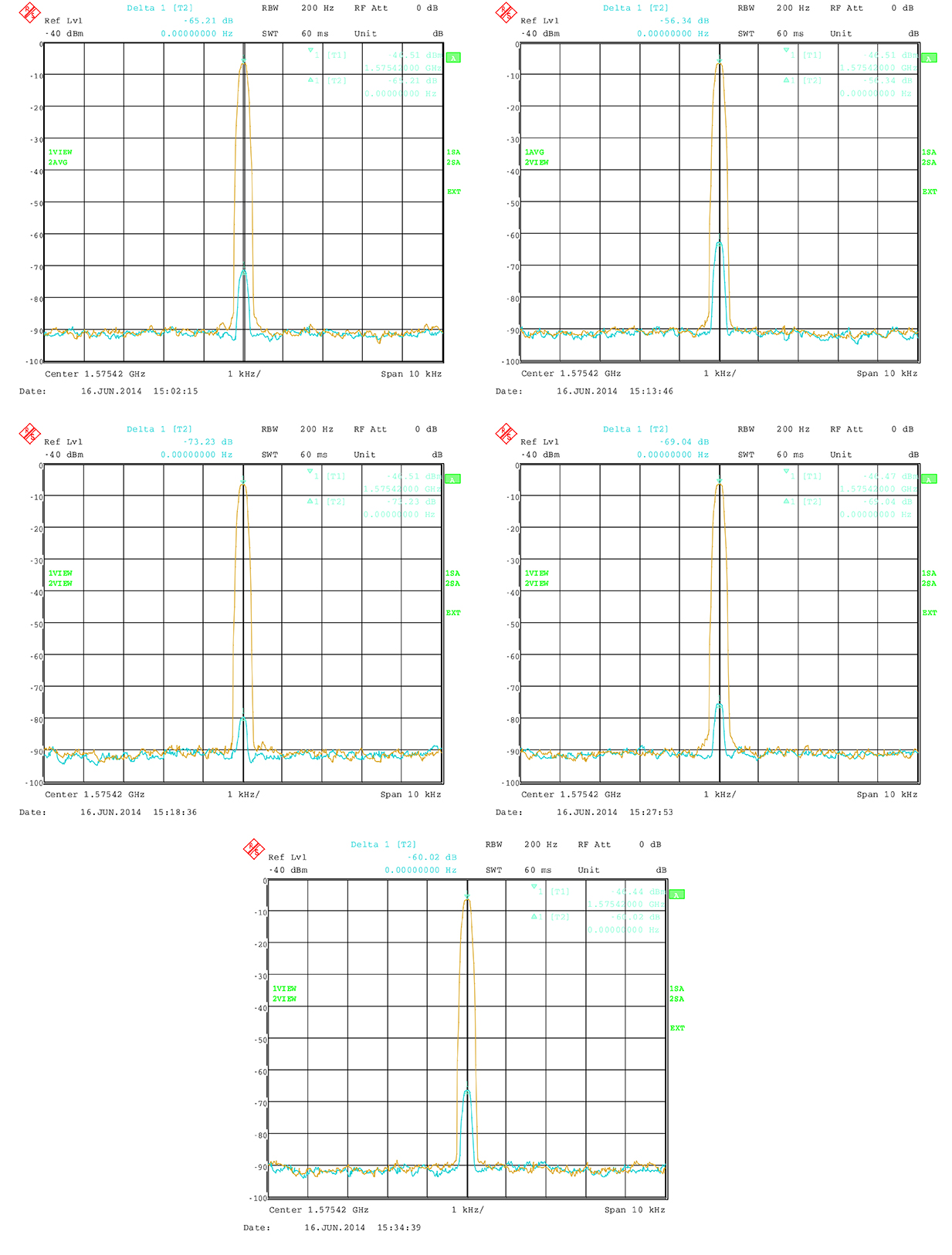
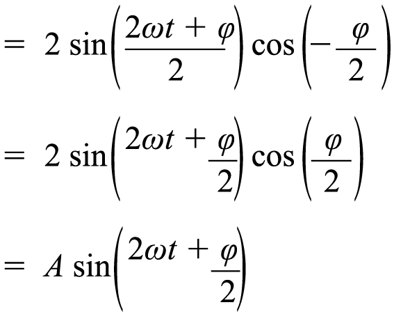
All modules are calibrated to garantee a carrier phase coherency of better than ±0.5°. Figure 1 shows the output at the RF master of two modules assigned to the same carrier but with a phase offset of 180°.
Figure 1. Carrier-phase alignment of the high-end simulator with six modules compared to the first module.
Theoretically, the resulting signal should be zero because of the destructive interference. In practice, a small residual signal remains because of component tolerance, small amplitude differences and other influences. Nevertheless the best cancellation can be seen at this point. The phase accuracy can now simply be estimated from the measured power level of the residual signal:
(1)
(2)
with
This means that the sum of two sine waves with the same frequency gives another sine wave. It has again the same frequency, but a phase offset and its amplitude is changed by the factor A. The factor A does affect the power level. If φ is 180° then A is 0, which means complete cancellation.
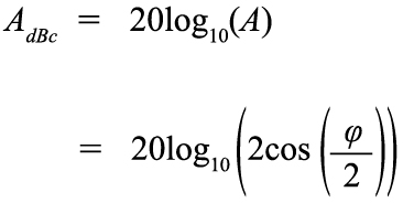
So A shows the power of the resulting signal relative to the single sine wave. It can also be transformed to dB:
(3)
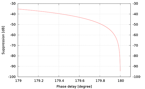
Figure 2 shows the carrier suppression as a function of carrier phase offset with a pole at 180ϒ.
Figure 2. Carrier suppresion as a function of phase delay.
The factory calibration aligns the modules to a maximum of 0.5ϒ misalignment. The measured suppresion therefore shall be better than 41.18 dBc. In practice, the residual signal is also caused by other influences, so that the actual phase alignment can be expected to be much better.
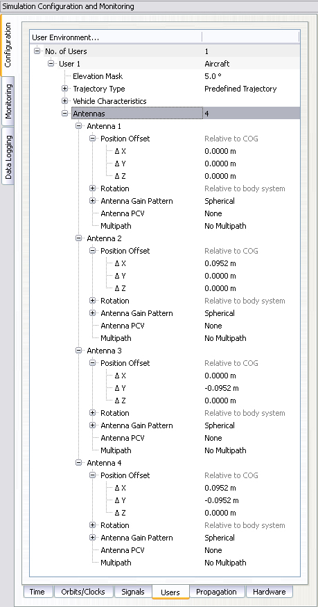
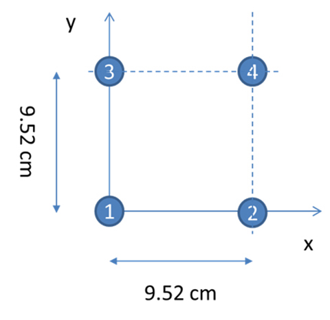
With four RF outputs, the received signal of a four element antenna can be configured very easily. Figure 3 shows the dialog to configure a four-element antenna with the geometry shown in Figure 4. Note that the antenna elements are configured in the body-fixed system with the x-axis to front and the y-axis to the right (inline with a north-east-down, NED, system when facing to north), while the geometry shown in Figure 4 follows an east-north-up (ENU) convention.
Figure 3. Configuration of individual antennas per receiver.Figure 4. Geometry of the GALANT four-element phased-array antenna (view from top).
The following sections give an overview of multi-antenna systems and discuss results from a measurement campaign of the German Aerospace Center (DLR) utilizing the simulator and the DLR GALileo ANTenna array (GALANT) four-element multi-antenna receiver.
Multi-Antenna Receivers
Multi-antenna receivers utilize an antenna array with a number of antenna elements. The signals of each antenna element are mixed down and converted from analog to digital for baseband processing. In the baseband, the signals received by the different antenna elements are multiplied with complex weighting factors and summed. The weighting factors are chosen in such a way that the received signals from each antenna element cancel out into the direction of the interferers (nulling) and additionally, for advanced digital beamforming, such that the gain is increased into the direction of the satellites by forming of individual beams to each satellite. Because all these methods work with carrier phases, it is important that in the simulation setup, the signals contain the correct carrier phases at the RF-outputs of the simulator corresponding to the user satellite and user-interferer geometry, and the position and attitude of the simulated array antenna.
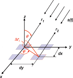
Figure 5 presents the geometry of a rectangular antenna array with 2×2 elements and a signal s(t) impinging from direction (ϕ, θ).
Figure 5. Parallel wavefront impinging on a rectangular array with 2×2 elements.
The spacings of the elements dx, dy are typically half a wavelength, but can also be less. The range difference for antenna element i relative to the reference element in the center of the coordinate system depends on the incident direction (ϕ, θ) and the position (m=0,1, n=0,1) of the element within the array:
(4)
The corresponding carrier phase shift is:
(5)
For CRPA and adaptive beam forming applications, the differential code delays may be neglected if they are small compared to the code chip length. However, it is essential that the carrier phase differences are precisely simulated, because they contain the information about the incident direction of the signal and are the basis for the array processing in the receiver. For instance, the receiver can estimate the directions of arrival of the incident signals from these carrier phase differences.
Now we consider a 2×2 array antenna. It can be simulated with the simulator with four RF outputs, where each output corresponds to one antenna element. In the simulator control software, a user with four antennas is set up, where the position of each antenna element is defined as an antenna position offset relative to the user position. In this approach, both differential code and carrier delays due to the simulated array geometry are taken into account, because the code and carrier pseudoranges are computed by the simulator for the position of each antenna element. However, the RF hardware channels of the receiver front-end may have differential delays against each other, which may even vary with time. If the direction of the satellites and interferers shall be estimated correctly by the receiver algorithms, a calibration signal is required to measure and compensate these differential hardware delays.
For the real antenna system, a binary phase-shift keying (BPSK) signal with zero delay for each antenna channel is generated by the array receiver and fed into the antenna calibration port. For the simulation, this calibration signal must also be generated by the constellation simulator.
In a simple way, a satellite in the zenith of the user antenna can be simulated, which has the same distance and delay to all antenna elements. Unfortunately, this simple solution includes some limitations to the simulated position and attitude of the user, because the user position must be at the Equator (if a “real” satellite is simulated in form of a geostationary satellite) and the antenna must not be tilted.
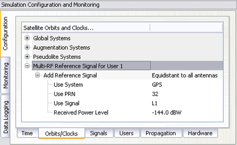
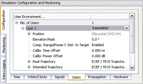
With a small customization of the simulator software, these limitations could be overcome. Figure 6 shows how to set up the generation of a reference signal. This reference signal can either be simulated as a transmitter directly above the user position, which follows the user position and thus allows also simulations offside the Equator, or simulated as a zero-range signal on all RF outputs, neglecting any geometry, which is the preferred method. The latter one is more or less identical to the reference/calibration signal generated by the receiver itself.
Figure 6. Configuration of a modulated reference signal.
The power level of this signal is held constant and is not affected by any propagation delay or attenuation simulated by the control center.
Attitude Determination
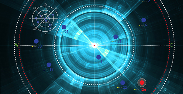
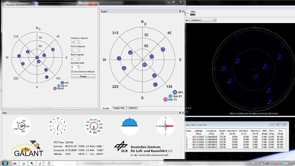
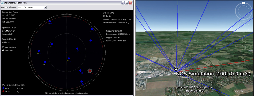
According to Figure 5, the phase difference measured between antenna elements is a function of the direction of arrival (DoA). Thus, the DoAs of the incident signals can be estimated from the phase differences. In the GALANT receiver, the DoAs are estimated by an EPSPRIT algorithm after correlation of the signals. Compared with the (known) positions of the GNSS satellites, this allows the estimation of the antenna array attitude. Figure 7 shows the sky-plot of simulated satellites as seen at receiver location (simulated on the right; reconstructed by the receiver from the decoded almanac in the middle and the DoA on the left). By comparison of the estimated DoAs of all satellites and the skyplot from the almanac, the attitude of the antenna is estimated (left). In addition, the attitude angles simulated by the simulator is given (right).
Figure 7. Simulating and estimating attitude with a multi-element antenna.
Simulation of Interference
It is possible to simulate some simple types of interference. Possible interference scenarios are:
Wideband Noise. By increasing the power of a single satellite of the same or another GNSS constellation, a wideband pseudo-noise signal can be generated. Using a geostationary satellite also enables simulating an interference source at low elevations and constant position. Use of power-level files also allow generation of scenarios with intermittent interference (switching on and off the interference) with switching rates up to 5 Hz.
CW or Multi-Carrier IF. By disabling the spreading code and navigation message, a CW signal can be generated. The simulator also allows configuration of subcarrier modulations. Without spreading code (or to be precise with a spreading code of constant zero) the generated signal will consist of two carriers symmetrically around the original signal carrier (for example, configuring a BOC(1,1) signal will create two CW signals at 1.57542 GHz ± 1.023 MHz, thus producing “ideal” interferer for the Galileo E1 OS signal.)
Depending on the number of Merlin modules per RF output, interference to signal ratios up to 80 dB could be realized, limited by a dynamic range of 40 dB within one module and additional 40 dB range between two modules. However, the maximum power level of one individual signal is currently limited to -90 dBm. If only one channel per module is used, the maximum power level of this single signal can be increased by another 18 dB (for example, by using one module solely for interference generation and another module for GNSS simulation).
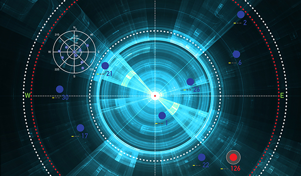
Figure 8 shows the simulated geometry for an interference scenario based on wideband noise generated by a geostationary satellite, producing –90 dBm signal power at the receiver front end. The interference source is very near to the direction of PRN 22 with a jammer power of –90 dBm, resulting in a jammer to signal ratio of J/S = 25 dB.
Figure 8. Geometry for the wideband noise interference scenario.
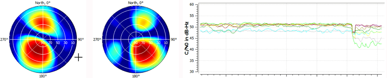
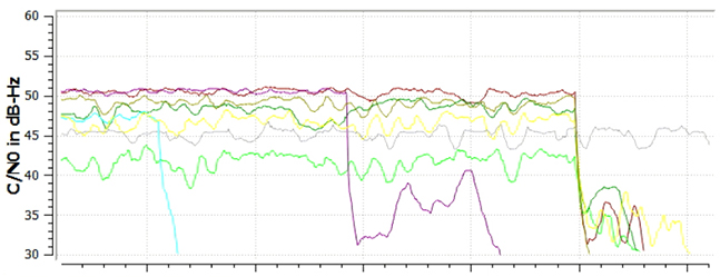
Figure 9 shows the two-dimensional antenna pattern as a result of the beam-forming before and after switching on the interferer. The mitigation algorithm tries to minimize gain into the direction of the interferer. As this also decreases gain into the direction of the intended satellite, the C/N0 drops by approximately 10 dB for PRN 22, because its main beam is shifted away from the interference direction. For satellites in other directions, the decrease in C/N0 is less: compare Figure9with Figure 10. However, the receiver still keeps tracking the satellite. After switching of beamforming, the signal is lost.
Figure 9. Beamforming for PRN 22 (light green line in lower plot) to mitigate for interference.Figure 10. Tracking is lost after switching off beamforming for individual channels (light blue, purple) and all channels (at the end of the plot).
Simulation of Spoofing
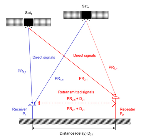
The simulation of a spoofing signal requires twice the resources as the real-world scenario, as every “real” LoS-signal must also be generated for the spoofing source. A simulation of an intentional spoofer who aims to spoof a dedicated position in this context is, however, very similiar to the simulation of a repeater ([un-]intentional interferer) device:
The repeater (re-)transmits the RF signal received at its receiver position. A receiver tracking this signal will generate the position of the repeater location but will observe an additional local clock error defined by the processing time within the repeater and the travel time between repeater and receiver position. A correct simulation for a multi-antenna receiver therefore has to superpose the code and carrier range as observed at the repeater location (considering geometric range between the transmit antenna of the repeater and the individual antenna elements) with the code and carrier ranges at the receiver location.
Instead of the location of the repeater P2, however, any intended location Px could be used to simulate an intelligent spoofer attack (Figure 11).
The simulator can generate such scenarios by configuring the position of the (re-)transmitting antenna and the intended position (for example, the position of the repeater). By calculating the difference between the real receiver position and the position of the transmitting antenna, the additional delay and free-space loss can be taken into account. The user may also configure the gain of the transmit antenna and the processing time within the repeater. Currently, this setup does only support one “user” antenna to be simulated. However, this feature combined with multi-antenna support will enable the simulator to simulate repeater or intelligent spoofer attacks in the future (Figure 12). To distinguish the “real” signal from the “repeated” signal, the “repeated” signal could be tagged as a multipath signal. This approach would allow simulation of the complete environment of “real” and “repeated” GNSS signals in one single simulator.
Figure 11. Geometry of repeater/spoofer and GNSS receiver.Figure 12. Simulator’s capability to simulate a repeater.
Manufacturers
The simulator producing the results described here is the NavX-NCS from IFEN GmbH. The simulator is valuable laboratory equipment for testing not only standard or high-end single-antenna GNSS receivers, but also offers additional benefit for multi-antenna GNSS receivers like the DLR GALANT controlled reception pattern antenna system.
The GNSS constellation simulator offers up to four phase-coherent RF outputs, allowing the simulation of four antenna elements with two carrier frequencies, each utilizing one single chassis being 19 inch wide and 2 HU high.
Simulation of intentional and unintentional interference is a possible feature of the simulator and allows receiver designers and algorithm developers to test and enhance their applications in the presence of interference to identify, locate and mitigate for interference sources.
Thorsten Lück studied electrical engineering at the universities in Stuttgart and Bochum. He received a Ph.D. (Dr.- Ing.) from the University of the Federal Armed Forces in Munich in 2007 on INS/GNSS integration for rail applications. Since 2003, he has worked for IFEN GmbH, where he started as head of R&D embedded systems in the receiver technology division. In 2012 he changed from receiver development to simulator technologies as product manager of IFEN’s professional GNSS simulator series NavX-NCS and head of the navigation products department.
Günter Heinrichs is the head of the Customer Applications Department and business development at IFEN GmbH, Poing, Germany.He received a Dipl.-Ing. degree in communications engineering in 1988, a Dipl.- Ing. degree in data processing engineering and a Dr.-Ing. degree in electrical engineering in 1991 and 1995, respectively. In 1996 he joined the satellite navigation department of MAN Technologie AG in Augsburg, Germany, where he was responsible for system architectures and design, digital signals, and data processing of satellite navigation receiver systems. From 1999 to April 2002 he served as head and R&D manager of MAN Technologie’s satellite navigation department.
Achim Hornbostel joined the German Aerospace Center (DLR) in 1989 after he received his engineer diploma in electrical engineering from the University of Hannover in the same year. Since 2000, he has been a staff member of the Institute of Communications and Navigation at DLR. He was involved in several projects for remote sensing, satellite communications and satellite navigation.In 1995 he received his Ph.D. in electrical engineering from the University of Hannover.His main activities are in receiver development, interference mitigation and signal propagation.