LabSat 2 now has the ability to record and replay satellite signals from the rapidly expanding Chinese navigation system, BeiDou. LabSat 2 users can now record and replay any combination of two channels from the three available constellations, GPS, GLONASS, and Beidou.
Existing LabSat 2 users can download the latest firmware (v2.0.0) and PC software (v2.6.14) to add this functionality with no cost.
There is a growing trend to include multi-constellation capability into new satellite navigation receivers, giving the end user better coverage in urban canyons, and overall improved positional accuracy, LabSat said.
There are now 14 operational Beidou satellites, and we have recorded a number of different files from Europe and China containing between 6 and 8 satellites. These scenarios are now included on the hard disk which is shipped with a LabSat 2, which can also be shipped out to existing customers on request.
The new firmware and software is now available from the Support section of the LabSat website. Follow the upgrade firmware instructions in the manual to upgrade your LabSat 2. For more information contact our LabSat Product Manager, Mark Sampson, [email protected].
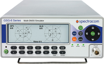
Spectracom announced its new L1+L2 dual-frequency 32-channel multi-GNSS simulator, the GSG-62. The GSG-62 offers multiple frequency band operation, multiple GNSS constellation simulation, and expansion capability for more frequency bands and channels, the company said.
The new simulator provides expanded capabilities for those who are testing more than GPS L1, according to the company. “We understand the challenges our customers have in fast-paced development, migration and delivery of products with ever changing embedded GNSS receivers,” said John Fischer, Spectracom CTO. “As such, we are excited to introduce this next-generation multi-signal instrument that allows for real-time scenarios, is intuitive to understand, quick to deploy and, given its design to support upgrades to L2C, L5, and future GNSS frequencies and systems, protects our customer’s investment in test gear.
Fischer continued, “In addition to a wide variety of technical challenges, we also understand our customers must balance the ability to quickly develop solutions and improve cost performance in their operations. We believe the price, unique features, and form factor of the GSG-62 will allow them to do both.”
The GSG-62 is designed for manufacturing and development testing with its ability to simulate all the visible satellites for the receiver under test. With 16 channels for L1 frequency and 16 channels for L2 frequency, channels can be assigned to GPS or GLONASS, P-code or C/A code. Channels may also be used for SBAS simulation of EGNOS, WAAS, GAGAN, or MSAS satellites, or for multipath and interference signals. The GSG-62 incorporates all the features of Spectracom’s previous models, including compatibility with GSG StudioView PC software for creation and editing of simulation scenarios via Google Maps.
CAST Navigation of Tewksbury, Massachusetts introduced its SGX GPS Satellite Simulator. With its compact size — 7 × 11× 3 inches — and weighing in at just over 4 pounds, the SGX is CAST’s newest and smallest fully capable simulator to date.
The new SGX replaces the CAST-SIMCOM Simulator which was a 17-inch, 50-pound simulator. The SGX lightweight portability operates on AC or battery power, features 16 channels of L1 C/A and P codes, and is extremely accurate and repeatable, according to the company.
Features include touch screen, individual satellite power control, and start and stop scenarios with a touch of a button.
The CAST-SGX is portable, affordable, lightweight and utilizes CAST long standing proven technology.
CAST has been in the GPS simulation and support business for more than 25 years, designing, developing, manufacturing, and integrating innovative GPS/INS simulators and associated equipment for government, military, prime vendor, and consumer markets.
CONTACT INFO
Company: CAST Navigation
Country: United States (USA)
Email: [email protected]
URL: http://www.castnav.com
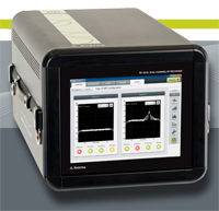
Averna, developer of test solutions and services for communications and electronics device makers, announces the availability of a field-ready multi-channel RF Recorder for RF applications covering 330 MHz to 2.5 GHz.
The Averna RP-5300 RF Recorder is an advanced tool for both field testing and performance testing, Averna said. With 50 MHz of recording bandwidth at 16-bits, it can record multiple GNSS signals in up to two bands (L1, L2, L5), such as GPS or GLONASS. Its compact size and integrated display was designed for field operation.
Wireless products need to perform well in the complicated and difficult-to-predict RF environments found in the real world. Simulators can bring the design up to a certain point in the development process, but Averna’s RF Recorder captures all the multi-path, interference and general degradation of signals that end-users will experience. Capturing the segment of spectrum of interest, from minutes to hours, allows a technician to return to the lab with data necessary to diagnose and solve the problem, while building a library of environments to harden their products for the future, Averna said.
“Recording live, impaired, RF signals of interest in the field, without demodulation or alteration, reduces the need for traditional field-testing of RF receivers,” said Brendan Wolfe, director of product management at Averna. “We are thrilled to bring to the GNSS market a portable and high-fidelity multi-channel RF recorder designed for the optimal capture of real-life RF environments.”
The RP-5300 comes preloaded with Averna’s RF Studio Recorder. RF Studio is workflow software for making trouble-free RF recordings, managing collected data, and analyzing or playing back collected RF environments. With RF Studio Recorder, the intended signals are captured during and after a recording session without the need for RF experts on site, Averna said.
Key features include:
50 MHz recording bandwidth to capture multi-GNSS signals
Two channels to capture signals operating at different frequencies
Up to 11 hours of recording time with external RAID (2×50 MHz channels @ 16-bit-depth)
Field-ready with an integrated touchscreen display, ruggedized chassis and compact size
Simple field setup, intuitive user interface and test-case profiles
For customers interested in a complete solution of RF recording to playback, Averna recommends the Averna RP-5300 Series be paired with the Averna URT-5000, a world-class RF Player and Signal Generator.
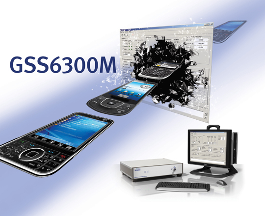
Spirent Communications today announced the launch of its new GSS6300M Multi-GNSS simulator designed for integration, verification, and production testing where a quick and accurate functional test is needed. The platform supports simulation of signals from individual or combined GPS/SBAS, GLONASS, and Galileo constellations, with eight satellites per constellation.
The GSS6300M supports two modes of operation — integrated into an Automated Test Equipment (ATE) environment or using Spirent’s SimCHAN software. For automated operation, the GSS6300M can be synchronized with other equipment and controlled remotely over Ethernet, IEEE-488 (GPIB), or RS232 interfaces. The SimCHAN software interface supplied with the GSS6300M enables the user to create unlimited scenarios and specify parameters such as user position, date, and time. Both modes support precise user control over power level and atmospheric effect selection.
“The GSS6300M is designed for customers who want an affordable, easy-to-use multi-GNSS test system with the quality, reliability and support that is expected from Spirent,” said Rahul Gupta, product manager with Spirent’s Positioning Technology business. “The GSS6300M enables testing of fundamental receiver functionality including time to first fix, sensitivity, and accuracy.”
The GSS6300M is now available for order. A field upgrade pack is available for existing Spirent GSS6300 customers who want to leverage the multi-channel capabilities of the GSS6300M.
Simulator company Racelogic, based in the United Kingdom, has been honored with two 2012 Queen’s Awards for Enterprise. The awards were given April 21 to 209 companies to mark Queen Elizabeth’s birthday. Racelogic was one of four companies to be honored with the awards for both Innovation and International Trade.
Racelogic won the Innovation award for advances in GPS/GLONASS test simulation, with customers such as Broadcom, ST-Ericsson, and Telefonica using LabSat to test their devices.
Almost 90% of Racelogic’s sales are now to countries other than the UK, with customers in 92 countries around the world. Racelogic received the International Trade Award to recognize this achievement.
“We are extremely proud to be named as a winner of these two awards, with many highly reputable companies in the UK competing for these honors,” Racelogic’s CEO, Graham Mackie, said. “As a company we continue to grow and now employ more than 50 people in the UK alone. We have distributors located all over the world who help us to market and sell our systems to a wide variety of markets and customers.”
All winners will be invited to collect their awards at a reception hosted by the Queen in Buckingham Palace later this year.
Spirent’s simulation systems have changed significantly from their technology beginnings, which can be traced back to World War II radars. The company and its technology have evolved to keep pace with today’s growing population of GNSS constellations and to meet the challenges that receiver manufacturers and users encounter in an ever-complex integrated GNSS environment.
In the early days of GPS when there were only enough satellites for a fix at odd times of the day or night, these nighttime expeditions were the only form of testing that we could get our hands on. Then as the constellation grew, we were delighted when eventually you could do open sky testing whenever you needed. It never even occurred to us that more exhaustive, more complex testing would become essential as time progressed.
If you walked into any GNSS manufacturer’s testing facility nowadays, the ubiquitous test rack at the heart of most test validation systems might well include a Spirent simulator of some vintage. I recall when we were bringing up receivers in engineering, one of our concerns was how the heck could we afford another one of these beasts for the guys down in production? After we already broke the bank when we managed to convince management that we couldn’t live without a Spirent, we were wondering who we’d push to the front of the line to tell the boss that we had to buy yet another one for the guys on the production line. At one time before a cut-down single channel box became available, we shared our simulator with production who operated the system remotely and a coax run provided RF onto the production floor. We still did open sky testing in R&D, but the complex validation scenarios would have been impossible for the team without our Spirent simulation system.
Recently I got to wondering where Spirent had come from and how come they had become one of the leading players in GNSS simulation. I did recall that they were UK based, that there were a number of name changes and that at one stage they also had receiver capability. So I got talking with John Pottle who’s always been my marketing window into Spirent, and Peter Boulton who’s been my principle technical contact. I was interested in Spirent’s background, their engineering capability, how they got where they are now and where they plan to go in the future.
Its not surprising that Spirent’s roots go way back in England to the period of the second world war. England developed radar as an early warning system that helped win the air combat Battle of Britain. Following the extensive blitz bombing of London, the UK government subsequently re-located the radar technology team well out of harm’s way to the distant and more secure southern tip of England, and that technology team formed the core of a high-tech group based in Paignton, Devon which eventually evolved to focus on GNSS simulation.
Southern England – Paignton base for Spirent.
It’s a nice area to live in, with fewer people, smaller towns and a very pleasant climate. So the technology guys and their families hung around and the government facility became Standard Telephones (STC) and Cables Defence Systems. Focusing in those days on travelling wave guides, cathode ray tubes, and radar amplifiers and the like, this business grew to include solid-state amplifiers, satellite communications and repeaters for fiber-optic networks. This all needed test equipment and a test division grew up to service STC’s technology groups.
As GPS came on line, the UK Government Royal Aircraft Establishment (RAE) needed GPS simulation capability to verify GPS system performance, and STC came up with a test system equipped with 6 dual-frequency satellite signal sources with additional jamming sources and a range of military data interfaces. The computer operating system was VMS running on a Digital Microvax2 platform, the software was written in DEC Fortran and the DOS-like user interface had textual menus with a graphics terminal for X-Y plots. Just like we had racks of equipment for the original single channel GPS receivers, GPS simulation systems started in the same way.
RAE GPS Simulation System 1987.
In parallel STC was also working on a contract to develop a military GPS receiver, and several of the GPS ASICS used in that receiver found their way into the simulator. Simultaneously, the RAE contract was extended to include provision of full SA-A/S capability, which was delivered in 1988. This classified system was used to formally evaluate the Rockwell-Collins 3A receiver SA-A/S implementation – at the time this test system was the only one available capable of emulating all the features of SA-A/S.
As it became clear in1988 that GPS would have a wider commercial market, STC began to invest in simulation systems for commercial receiver manufacturers.
STR2740 Simulator 1989.
STR2760 Simulator 1991.
With dual frequency and up to 10 satellite channels, the STR2740 was still quite large as it was based on the floor standing Microvax2. Porting the software to a desktop VMS workstation gave us the more familiar STR2760 that was first displayed at the ION-GPS-1991 convention in Albuquerque. This initial unit was actually purchased from the ION display show floor and STC had to hustle to quickly make more!
Then ownership passed to Northern Telecom in Canada, who was initially interested in STC’s fibre-optic communications technology and products. After a few years, Northern Telecom changed its name to Nortel – so then we all started talking about ‘Nortel simulators’. The next phase of internal development re-tuned the technology and the resulting 1997 STR4760 simulator boasted double the channel capacity and enabled the inclusion of GLONASS and SBAS capability.
STR4760 Simulator 1997.
In the same timeframe, development of a Controlled Radiation Pattern Antenna (CRPA) was underway in Paignton, but this didn’t quite fit with a business focus on testing, so the CRPA line was sold to Cossor, which was subsequently merged with Raytheon — and the well-known GAS-1 mil-spec CRPA was the outcome. The GPS receiver technology went along with the CRPA to Cossor and ultimately on to Raytheon.
In 1997 the Nortel name also disappeared as Bowthorpe in UK became the new owners and the group became known as ‘Global Simulation Systems’ and we then had “GSS” simulators for a period, but by 2000 the parent company changed its name to Spirent, and that name seems to have stuck.
When SA was switched off in 2000, the potential for commercial GPS became apparent to the Spirent team and this fired up investment in a brand new range of products for the commercial GPS L1 C/A code marketplace – units can often be found in use for single channel production testing, whilst other multi-channel simulators are in use for commercial, pre-production, R&D and verification.
Full L2C, L5 and M-code GPS modernisation was introduced in 2004 while retaining essential systems and scenarios backward compatibility. Spirent’s approach has been to endeavour to get to market early with new signal capability for early adopters.
Support for all Galileo signals and services arrived in 2006 and the GSS8000 series in 2008 added a wide range of additional signal generation capabilities as well as GLONASS L1/L2 and QZSS.
GSS8000 Series Simulator 2008.
SimGEN has been the Microsoft Windows user interface provided by Spirent since around 2002.
SimGEN interfaces to external receivers, and enables external vehicle trajectory input via various interfaces. High speed remote control is also possible and logging/displaying/plotting is also available for report generation and results analysis.
So today, Spirent has accumulated a significant range of simulation capabilities:
Galileo RF constellation simulators for all frequencies & services
GPS L1 C/A and P/Y, L2C, L5, M-Code, M-Noise, L1C
GPS SBAS (MSAS, WAAS, EGNOS, Gagan)
GLONASS L1/L2
QZSS L1 C/A, SAIF, L1c, L2c and L5 signals
R&D systems for the IRNSS regional system program
Automotive sensor simulation
SimGEN emulation of Aircraft Landing Augmentation System (GBAS)
SimINERTIAL adds stimulation of test Inputs for several types of inertial sensors.
Equipment for both GNSS manufacturing and field testing
With around 25 in-house engineers and a number of outside consultants, the technical team is not huge. But with 27 years of accumulated experience in GNSS simulation, and a large ‘vault’ of key technologies, Spirent is well positioned for the challenges that the world’s multiple, evolving GNSS constellations are presenting to manufacturers.
So what’s next for the Spirent simulator business? Well the Chinese COMPASS constellation is coming on fast, so even though there is still no complete, usable public ICD available, Spirent has adopted the same approach used when release of the Galileo ICD was restricted by ESA – Spirent supplies a COMPASS simulator which has the ‘real’ modulation and frequencies, but the customer inputs the navigation messages.
Spirent is also getting some traction from users who want simulation systems to model specific applications – like car motion sensors to simulate the inputs of in-vehicle navigation system, or full ground segment monitoring and fully integrated message generation for GBAS aircraft landing systems or simulation designed for testing of integrated GPS/Inertial systems.
The days of relying on GNSS alone for navigation and positioning may be fast disappearing, so its likely that things will get even more complex. While there may be some significant questions, such as which combination of GNSS frequencies/signals/constellations to choose from to optimise performance for a particular application, the focus for developers is getting much broader than GNSS or even multi-GNSS alone. Or you could say that the problem has shifted from proving GPS receiver performance alone, to proving, and improving systems and applications performance to meet increasingly demanding end-user needs.
For example, in defence applications where integrity and resilience are key focus areas, inertial navigation is used to complement GNSS, and adaptive antenna technology helps to overcome intentional interference threats. In commercial markets, getting good accuracy everywhere has led to hybrid approaches that include cellular and Wi-Fi positioning and augmentation from MEMS inertial sensors.
Spirent’s product road maps appear to reflect this shift in customer needs. This year we should expect to see Spirent GNSS/inertial test capability for commercial inertial sensors, and also manufacturing and functional testing of consumer devices that include not only GNSS but also Wi-Fi, Bluetooth and other emerging technologies such as near-field communications (NFC) contactless technologies.
So a varied range of GNSS simulation capabilities which match up to the challenges which users face in the real world — and with over 800 simulations systems supplied world-wide, Spirent is surely setting the pace for the evolving GNSS & systems simulation marketplace.
Five experts share what original equipment manufacturers need to know about testing their GNSS devices during product development.
System Health
John Pottle, Spirent Positioning Technology
Most people are aware that simulation forms a key part of GPS receiver development and testing.
However, simulators are also used as critical tools in other areas, from the development of a new GNSS system to testing system problems and effects of interference.
From the beginning of the Galileo program, simulators have been used to enable development of the ground segment monitoring receivers. These Ground Sensor Stations continuously monitor the performance of the Galileo satellites and provide information to the Galileo Control Centre in Fucino, Italy, from where correction messages are generated.
Galileo RF Constellation Simulators were also used for research and development testing of the initial user segment receivers for the Galileo system. These included not only the Open Service receivers but also development of the initial Public Regulated Service receivers that include the encryption algorithms.
Similarly, simulators have been used for many years to test receivers that actually fly in space, including on the GPS satellites themselves as well as missions like the Space Shuttle.
When GPS has a problem, the industry oftentimes relies on simulators to recreate the problem in the laboratory to help understand the issues and find fixes.
For example, when SVN-49 satellite issues were first noticed in April 2009, simulator scenarios were generated and made available to the industry in co-operation between Spirent Federal and the GPS Directorate. These scenarios helped with the characterization of the problems on board the satellite and also with looking at possible fixes.
More recently, simulators and other receiver test approaches were widely used to help with the understanding and quantification of the impact of the proposed LightSquared broadband network on GPS systems.
A wide range of simulators was deployed in the testing that was led by the Technical Working Group set up under the auspices of the FCC. The sub-groups of the TWG used not only RF constellation simulators but also live sky sample and playback systems for testing. A wide range of test approaches was adopted, including conducted testing (from the RF simulator via co-axial cable into the receiver front-end, bypassing the antenna and with antenna effects being modeled as part of the simulation where required) and over-the-air test approaches in small and large chambers.
Following the LightSquared testing the current debate is whether it would be helpful to have certification or standardization of GPS and other GNSS receivers in some form. Standards for GPS systems already exist in the safety critical areas such as aviation and maritime as well as in areas such as emergency location (E-911). Discussion on extending current A-GNSS standards to include other positioning methods such as Wi-Fi positioning and MEMS sensor-based positioning are also underway in various standardization forums.
Whatever the problems the industry and systems face today and into the future, one thing seems assured — simulation will remain a key tool to help create a repeatable and controllable environment to enable understanding and continuous improvements in navigation and positioning technology.
John Pottle has more than 20 years of experience in technical, marketing, and business development positions in communications and navigation. He is responsible for marketing at Spirent Communications’ Positioning Technology division in Paignton, UK. He trained as a communications engineer and holds a master’s degree in business administration.
Debug, Verify
Paul Myers, Spectracom
The affordability, shrinking size, and power requirements of GPS and GNSS receivers are accelerating their integration into a multitude of products: personal navigation, safety devices such as alarms systems and cell phones, telematics devices, camera systems, and timing and control systems. But the additional capabilities of position, navigation, and time/frequency synchronization come with an increased cost of test and verification.
Traditional lab bench development and field testing demonstrate operational capabilities. However, these methods alone may not reveal the subtle issues and fatal flaws found in the real world. Lab testing often demonstrates only the best or worst your test cases can offer. Furthermore, field testing only checks conditions and GNSS constellation operation for your location at specific times. Most integrators do not have the luxury of testing their product in the multitude of places their customers might use their product. This is where the application of a GNSS simulator adds value. GNSS simulators allow repeatable testing of real-world situations under a variety of test conditions and in a diverse set of simulated places at different times.
The first step of GNSS integration is to define requirements based on the product use cases. The prudent test designer realizes lab tests, field tests, and simulation all have a place in the product development cycle, and later in maintenance.
Once the product requirements and use cases are known, the type of GNSS receiver can be selected, and supporting software and hardware design can begin. High-level test design is best performed as you design your product. This allows you to better schedule and estimate project time and costs.
Your type of product dictates your test plan design. You will need to allocate some testing to the lab, some to the field, and some to GNSS simulation. The right test case allocation depends on your product type.
Depending on your product requirements, you may have to define navigation test cases, positioning test case, or time and frequency synchronization performance test cases. Position and navigation products require a GNSS receiver with sufficient accuracy and update rates to provide accurate position and navigation data. Time and frequency products, whether mobile or stationary, require a 1PPS output with a serial time code output and sufficient stability and precision to discipline an oscillator to generate precise time and frequency.
Identify which test cases require execution in the lab setting, which require GNSS simulation, and which demand field testing, then allocate them in the test plan to project phase. The old adage that lab testing can’t catch everything that field testing finds can be cheated by the use of GNSS simulation. GNSS simulations reduce cost and schedule time by avoiding repetitive field testing and integration cycles. Plus, simulation testing allows iterative development and retesting by virtually testing in the field.
For example, positioning and time and frequency products can initially utilize lab testing to iteratively develop features and accurately measure system performance. The GNSS simulation can then be leveraged to model the field environment under many different conditions, locations, and times. Finally, field beta testing then can validate the lab and simulation results with real-world beta site experience.
Similarly, mobile navigation or time/frequency products benefit less from lab bench testing and require more in field testing to verify operation under real-world navigation scenarios. Solution accuracy can be baselined in the lab, but accuracy in the field is vital for product success. A GNSS simulator can be used to test conditions, remote locations, and time/dates impossible to achieve using the real GNSS signals. This reduces some of your testing to defining use cases and making simulator configuration files. Without simulation you can only develop, ship, and then fix bugs found by your customers — all the while sweating bullets waiting for users to report problems found from untested situations or when leap seconds occur.
Finally, don’t forget to create regression tests from the verification testing already performed; this enables you to continue to maintain and re-verify product performance. Again, leverage the lab environment, GNSS simulator test cases, and your shipping product to create a product maintenance process. Remember, a smart designer develops the requirements, use cases, and test cases before completing design and development. And a smart integrator uses a GNSS simulator to field test the product before it ever leaves the lab!
Paul Myers is a principal engineer at Orolia USA. He has more than 20 years of experience in embedded systems development in defense and commercial applications. He has a BSEE from Clarkson University, an MSEE from Syracuse University, and is a graduate of General Electric’s Advanced Course in Engineering.
Modern Requirements
Markus Lörner, Rohde & Schwarz
Receivers for satellite-based navigation systems such as GPS and GLONASS can be found nowadays in many electronic devices to support location-based services. The faster and more accurately the actual position can be determined, the better the user experience will be. The devices are typically used not only in open space, where the reception conditions would be ideal, but more often in densely populated cities, where harsh conditions such as urban canyons with obscuration and multipath propagation are prevalent. To ensure optimal performance, the receiver needs to be tested and verified with repeatable scenarios that can only be provided by a GNSS simulator.
Standard tests such as time-to-first-fix and location accuracy need to be conducted for all GNSS receivers and modules.
When using a GNSS simulator, this is a straightforward task. The definition of harsher scenarios with multiple obstacles that generate obscuration and reflections is already much more complex, as there are no common test procedures defined. As a result, vendors must specify and generate their own test plans. This requires very flexible GNSS simulation solutions that allow direct access to the satellite constellation configurations.
Many of today’s state-of-the-art receivers are multimode receivers, which means that they support, for example, both GPS and GLONASS. They can therefore use satellites from both systems and still provide a location fix, whereas a single system receiver does not see enough satellites to obtain a stable 3D fix. Each of the two systems must be verified on its own, of course, but additional tests with both systems active are also required to make sure the receiver works properly with these hybrid scenarios. One additional test is to verify receiver performance when the system time of the different GNSS systems is drifting, since these system clocks are controlled and monitored separately.
Increasingly more important is receiver performance in the simultaneous presence of many other signals, such as Bluetooth or WLAN, at a much higher signal level. Another aspect is that cross-correlation distortion from other GNSS systems degrades the desired GNSS signal. Again, no official test requirements are defined in general. The Federal Aviation Administration instructs aviation receiver manufacturers to perform tests with additive noise and CW interferer. Ideally, these tests can be done inside the GNSS simulator.
To summarize, GNSS systems are used more often in especially harsh reception conditions, but users expect perfect location information almost everywhere. To ensure optimal user experience, greater emphasis must be put on testing. Addressing these needs requires a full-featured GNSS simulator, which ideally can also be used as an interference generator for Bluetooth and other standards.
Markus Lörner is a product manager for RF signal generators and power meters at Rohde & Schwarz headquarters in Munich, Germany. He joined the company in 2000 after receiving his degree in electrical engineering from the University of Erlangen-Nürnberg.
Success Factors
Mark Sampson, RaceLogic
With more devices now using mobile location-based services and the completion of the GLONASS constellation, it has become more important than ever that companies who incorporate multi-GNSS engines into their products have a reliable, cost-effective way of accurately testing these devices and applications.
Developing GNSS-enabled products within budget and to timescale has, however, always been a challenge. The traditional methods of repetitive field testing and expensive signal laboratory simulation have proved ineffective at offering engineers the repeatability and realism required to test how their devices perform in everyday, real-world scenarios.
Introduction of multi-constellation GNSS simulators has enabled R&D departments to effectively record and replay real-world signals in testing facility conditions, all at a cost-effective price. Providing engineers with the repeatability, consistency, and reliability required to effectively test a range of GNSS-enabled devices, these compact and light-weight systems cut development times by reproducing genuine satellite signals, all from the comfort of your desk.
Before you begin to see how your device performs, there are a number of factors to consider to assure successful GNSS testing is carried out. One of these considerations is the need to clearly pre-define objectives depending on the device or application to be tested and the stage in the product’s development cycle. These can include specific tests for the development of the product chipset, its module, and verification testing to ensure the product meets targets before it is released.
The other consideration is having to test signal reception from multiple satellite constellations to a single GNSS receiver — a special challenge for R&D departments, with system-specific reference frames, system-specific propagation models, timing offsets, date rollover, and cross-system impacts all having to be taken into consideration before successful GNSS testing can be implemented.
After these points have been resolved, using a simulator to simulate scenarios via live-sky signals couldn’t be easier. Connecting directly to an RF antenna input of a GPS engine and simulating the signals associated with navigation using GPS/ GLONASS / Galileo and satellite-based augmentation systems (SBAS), you can carry out highly repeatable tests without leaving the office.
Working alongside a simulation software, engineers can generate a data file that can be replayed on a simulator based on a user-generated trajectory file. This allows you to simulate almost any kind of dynamic profile, at a set time and date, anywhere in the world.
Mark Sampson has more than 15 years of experience in GNSS technology. He works closely with businesses such as Bosch, Intel, Samsung, and Telefonica, providing expertise in testing GNSS devices, applications, and integrations.
Why Test?
John F. Clark, CAST Navigation
Testing the operation and performance of a GPS receiver can be a time-consuming and complicated process. To achieve this effort, some receiver manufacturers and system integrators use a combination of receiving live sky GPS signals with an outside antenna as well as receiving signals produced from a GPS simulator.
While you may think that it is easy enough to just go out and put up an antenna to receive the GPS signals from the live sky, you need to ask yourself what it is that you are actually evaluating. Are you evaluating a position solution that contains the effects of local variations such as antenna shading due to placement of the antenna in relation to an existing structure? Are you seeing some effects of multipath being induced to the receiver solution? Is the placement of the antenna causing a larger than expected error? Will you get different navigation results by testing at different times of day? How do you test your receiver under dynamic conditions that contain vehicle motion? Due to the volatility of the GPS constellation, a satellite simulator provides you with repeatable and customizable test conditions.
A GPS simulator must model all transmission paths, anomalies, satellite motion, and user motion to provide you with the ability to control all aspects of the GPS signal to accomplish repeatable testing under known environmental conditions. A GPS simulator should also be capable of allowing you to define a specific time, date, and almanac to be utilized during the simulation, thus enabling you to reproduce the same GPS constellation characteristics as seen from a live-sky antenna for a specific time and location.
You can also use a GPS simulator to assist with the evaluation of new software builds for receivers, characterize a receiver, or evaluate multiple GPS receivers under identical operating conditions. A few simulators also provide the ability to drive an inertial interface, to assist with aircraft avionics integration and testing in a dynamic environment without leaving the laboratory for expensive flight testing.
Using a GPS simulator provides you with the ability to evaluate some operational specifications like time-to-first-fix, time-to-subsequent-fix, low signal-to-noise ratios, receiver loss of RF, reacquisition after signal loss, tracking of rising and setting SVs, and more.
Some GPS simulators also allow you to define and simulate multipath signals. The ability to define the characteristics of multipath signals provides you with a very precise and repeatable signal source to accurately measure and quantify the effects of multipath signals on carrier-phase measurements and receiver performance. This allows you to accurately characterize multiple types of GPS receivers, enabling you to select the appropriate receiver for use in different types of applications and operating environments.
John F. Clark is vice president, engineering, for CAST Navigation, LLC. He has more than 25 years of experience in the GPS industry, and has worked at CAST since 1991.
CAST Navigation of Tewksbury, Massachusetts introduced its SGX GPS Satellite Simulator. With its compact size — 7 × 11× 3 inches — and weighing in at just over 4 pounds, the SGX is CAST’s newest and smallest fully capable simulator to date.
The new SGX replaces the CAST-SIMCOM Simulator which was a 17-inch, 50-pound simulator. The SGX lightweight portability operates on AC or battery power, features 16 channels of L1 C/A and P codes, and is extremely accurate and repeatable, according to the company.
Features include touch screen, individual satellite power control, and start and stop scenarios with a touch of a button.
The CAST-SGX is portable, affordable, lightweight and utilizes CAST long standing proven technology.
CAST has been in the GPS simulation and support business for more than 25 years, designing, developing, manufacturing, and integrating innovative GPS/INS simulators and associated equipment for government, military, prime vendor, and consumer markets.
u-blox and Rohde & Schwarz (R&S), a supplier of test and measurement equipment, have successfully concluded a simulation of the European Galileo satellite positioning system. The test, carried out with the R&S SMBV100A vector signal generator and its GNSS simulation options, verified the u-blox proof-of-concept and the compatibility of u-blox receiver technology with the Galileo transmission protocol.
The cooperation with R&S is also being extended to the Russian GLONASS satellite system, which is targeted to be fully operational with 24 satellites in 2012.
“Our close cooperation with R&S has proven to be a valuable and strategic asset, allowing us to develop advanced satellite receiver technology well before the actual satellites are available” said Clemens Bürgi, vice president of software development at u-blox.
“u-blox, with its depth of expertise in GNSS technologies, has helped us to validate our satellite simulator technology,” said Andreas Pauly, head of R&D Signal Generators Baseband at Rohde & Schwarz. “Now we have developed cutting-edge test equipment that simulates the protocol and physical layer.”