MediaTek, China Telecom and Xiaomi have announced an upgrade to its real-time kinematic (RTK) high-precision positioning technology. The joint development integrates 5G connectivity, advanced chip design and Xiaomi’s smart technology.
RTK technology is usually found in professional surveying tools, but will now be available for location and positioning in smartphones, cars and city networks, according to the companies.
The newly upgraded RTK system enables outdoor positioning with sub-meter accuracy and fast response times. Leveraging 5G network infrastructure, smart data transmission, and close chipset-mobile software coordination, the system could be widely implemented on smart city infrastructure, autonomous driving, and smart transportation.
This partnership is part of Xiaomi’s growth beyond smartphones into urban development and smart mobility technologies under the Xiaomi HyperConnect banner.
The improved collaboration between MediaTek’s cutting-edge chipsets, China Telecom’s network, and Xiaomi’s hardware-software ecosystem enables an optimized RTK performance model that can potentially redefine how smart devices interact in real-world environments.
Innovative chip offers multiple ultra-low power connectivity options and low-power processing for internet of things (IoT) market
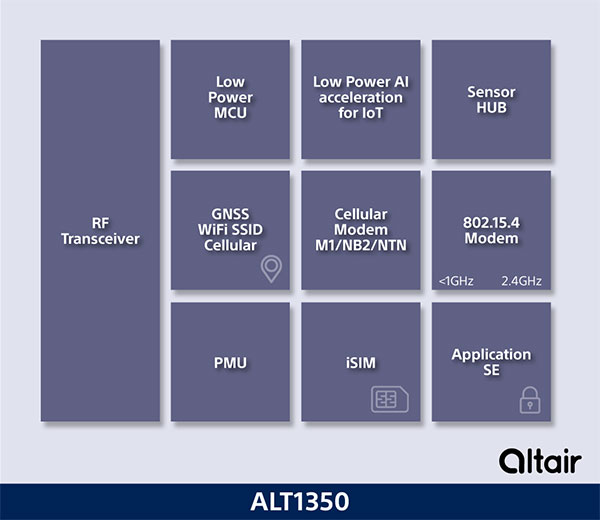
Sony Semiconductor Israel has launched the ALT1350 for the global market. The ALT1350 is a cellular LTE-M/NB-IoT chipset designed to enable additional low-power wide-area (LPWA) communication protocols, as well as GNSS, in a single chipset.
The ALT1350 incorporates a sensor hub to collect data from the sensors while maintaining ultra-low power consumption. It also provides cellular and Wi-Fi-based positioning and is tightly integrated to provide power-optimized concurrent LTE and GNSS to accommodate various tracking applications, which can be demanding with a single chip.
“The market demand for this multiprotocol, ultra-low power IoT chipset is intensifying, and Sony’s ALT1350 chipset meets that demand,” said Nohik Semel, CEO at Sony Semiconductor Israel. “This is the game changer we’ve been waiting for, which will enable IoT deployments, utilizing universal connectivity on edge processing and multiple location technologies.”
Diagram: Sony
The ALT1350 is an advanced cellular IoT solution, with architecture that resolves IoT service provider’s power-consumption concerns. Its optimized standby mode (eDRX) reduces power consumption by 80% when compared to the current generation and by 85% when using it to send short messages.
Overall improvements in the system’s power consumption will enable four times longer battery life for a typical device, enabling additional functionalities and use cases with smaller batteries.
The ALT1350’s sub-GHz and 2.4 GHz integrated transceiver enables hybrid connectivity for smart meters, smart cities, trackers and other devices. This enhances coverage, reduces costs and further decreases power consumption using IEEE 802.15.4-based protocols such as Wi-Sun, U-Bus Air and wM-Bus, in additional point-to-point and mesh technologies.
The chipset is designed to support the wide-ranging market needs of utilities, vehicle, tracking devices, smart cities, connected health and other verticals. Device manufacturers across all verticals can take advantage of its low power consumption, long-lasting battery life, mature Release 15 LTE-M/NB-IoT software stack, and future compatibility with 3GPP release 17.
All these guarantee longevity and ensure the ALT1350 will operate with 5G networks. It contains an additional LPWA radio transceiver with targeting operation in <1 GHz and 2.4 ISM bands for universal connectivity options.
The chipset provides advanced on-the-edge low power processing capabilities, ranging from data collection, low power AI/ML processing of the data, and MCU to enable IOT applications on the chip.
The device is now sampling to lead customers and will become commercially available in 2023. The ALT1350 also includes a secure element for application usage and integrated SIM designed for PP-0117 to meet GSMA requirements.
By J. David Grossman Vice President of Regulatory Affairs Consumer Technology Association
This January, the annual Consumer Electronics Show (CES) — owned and produced by the Consumer Technology Association (CTA) — returned to Las Vegas. As the premier global platform for innovation, each year CES showcases the latest and greatest consumer technologies, from smartphones and wearables to self-driving trucks and electric cars.
GPS continues to play a central role in the technology we use daily. At CES, GPS-enabled technologies are found in nearly every product category, including 5G, internet of things (IoT), smart cities, vehicle tech and fitness wearables.
They are also among the CES 2022 Innovation Awards honorees, such as a connected bracelet that can alert emergency contacts and a robot that can identify the difference between crops and weeds.
How did GPS come to play such a critical role in devices as diverse as drones and smartphones?
Over the past 40 years, GPS has transformed from its origins as a military technology to one that no consumer or business can live without. During the 1990s, CTA members such as Panasonic and Sony pioneered commercially available GPS receivers.
At CES 1998, Garmin introduced StreetPilot, described as “one of the first practical and affordable GPS-based road navigation devices” and paved the way for huge growth in the consumer GPS market.
By the 2000s, GPS was no longer just a stand-alone technology. Following new Federal Communications Commission requirements, GPS-enabled smartphones opened the door for all-in-one devices. These products could deliver turn-by-turn navigation or identify the location of a lost or stolen device. In more recent applications, GPS technology provides the foundation for ever-more-complex mobile applications.
Opening of the 2022 Consumer Electronic Show. (Photo: Consumer Technology Association)
Foundational Technology
The evolution of GPS reflects a broader industry trend: innovators integrate foundational technology into successive generations of products, spurring development of new products and services. We’ve seen the same pattern play out for Wi-Fi, Bluetooth and Near Field Communication (NFC), which enables the latest tap-to-pay technologies. Hundreds of companies simply would not exist without free, global access to GPS signals!
With GPS, ridesharing companies such as Lyft match drivers and passengers, lead drivers to a precise pick-up location, and chart out a safe and efficient driving route. GPS-integrated smartwatches allow runners and cyclists to easily track pace and distance, a huge boon for many of us in the pandemic era. Closer to home, GPS-enabled pet collars help families keep tabs on their furry friends.
Revolutionary
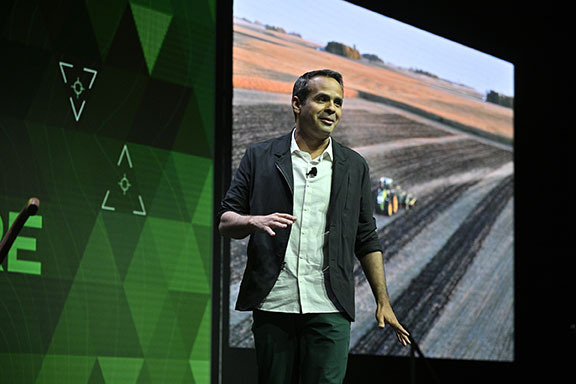
Beyond the technology we use daily, GPS technology is also revolutionizing such industries as agriculture. Thanks largely to GPS, centuries-old businesses are now technology companies. For instance, John Deere leveraged its 185-year history of building tractors and combines GPS with other location technologies to steer semi-autonomous tractors with centimeter accuracy. In addition to the time and efficiency benefits for farmers, technologies like these support sustainable agriculture by reducing the use of pesticides, water, seed and fertilizer.
John Deere held a Media Days press conference at Mandalay Bay during CES 2022. (Photo: Consumer Technology Association)
The success of GPS is important for our industry’s success, and I am proud of the role GPS plays in everyday life. Modernization of GPS, supported by the U.S. government and industry, will enhance the accuracy, reliability and resiliency of the technology, which in turn will ensure GPS remains central to the innovation economy.
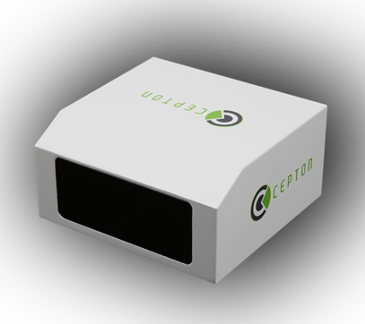
Cepton, a provider of automotive lidar solutions, will showcase its automotive-grade, long-range Vista-X90 lidar device at two upcoming tradeshows in Europe: IAA Mobility 2021 in Munich, Germany (September 7-12) and AutoSens in Brussels, Belgium (September 15t-16).
Photo: Ception
Vista-X90 combines high performance, auto-grade reliability and low cost to meet the critical requirements for mass-market automotive applications. During both events, Cepton representatives will be available to talk about Cepton’s lidar offering for a range of smart mobility applications, including advanced driver assistance systems (ADAS), autonomous vehicles (AV) and smart infrastructure.
With a compact and embeddable design, Vista-X90 is optimized for ease of vehicle integration, offering multiple placement options, such as in the headlamp, in the fascia, behind the windshield, or on the roof. Featuring Cepton’s next-generation ASIC technology, the Vista-X90 supports AUTOSAR and over-the-air (OTA) functionality, with advanced capabilities for functional safety, cybersecurity, and extrinsic calibration.
Visitors to the Cepton booth at IAA and AutoSens will also be able to learn about Cepton’s award-winning lidar solutions portfolio that extends beyond automotive and supports smart infrastructure applications such as smart roads and rail, electronic tolling, and more.
Cepton provides intelligent, lidar-based solutions for a range of markets such as automotive (ADAS/AV), smart cities, smart spaces, and smart industrial applications. Cepton’s patented MMT-based lidar technology enables reliable, scalable and cost-effective solutions that deliver long-range, high-resolution 3D perception for smart applications.
Founded in 2016 and led by industry veterans with more than two decades of collective experience across a wide range of advanced lidar and imaging technologies, Cepton is focused on the mass market commercialization of high performance, high quality lidar solutions. Cepton is headquartered in San Jose, California, USA, with a presence in North America, Germany, Japan, India, and China, to serve a fast-growing global customer base.
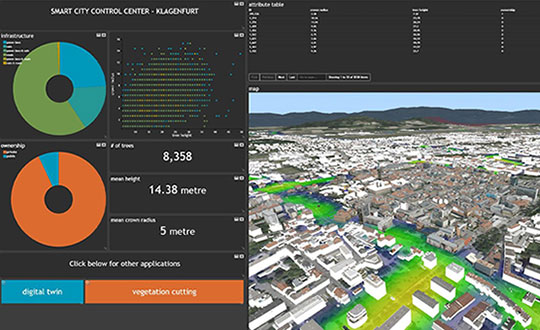
Hexagon’s Geospatial division has launched M.App Enterprise 2021, a significant update to its platform for creating geospatial and location intelligence applications. The latest release features new browser-based 3D capabilities and enhanced visual effects, plus the ability to create and configure custom applications more easily.
M.App Enterprise 2021 adds complete and seamless integration with Hexagon’s LuciadRIA. Now, users can access LuciadRIA’s 3D features, including support for panoramic imagery, shading, ambient occlusion and other visualization effects, to build browser-based solutions with no development necessary.
The latest version also features a new browser app configurator that makes it even easier to create spatio-temporal dashboards, known as Smart M.Apps. Additionally, Feature Analyzer has been expanded to allow users to add and manage multiple datasets on the fly and set up workflows. These enhancements enable more dynamic configurations, allowing field workers to be alerted quickly when action is required.
The city of Klagenfurt, Austria — a long-time Hexagon customer — has already begun using M.App Enterprise 2021 to create a city app platform that features a detailed 3D urban landscape of the entire city.
“This opens up endless possibilities for applications to automate several manual processes within different departments of the city,” said Günter Koren, head of the department of surveying and GIS at the city of Klagenfurt. “We believe M. App Enterprise will be an essential step in our journey to become a smarter, safer city for our 100,000 citizens.”
The latest release contains other new features and improvements, including an overhauled style editor, a new default dark theme, options for customized theming and full support for SAP HANA databases.
“M.App Enterprise 2021 helps organizations achieve smart monitoring of their cities, infrastructure and services by seamlessly incorporating location intelligence into enterprise systems and workflows,” said Georg Hammerer, chief technology officer of Hexagon’s Geospatial division. “With augmented visuals and dynamic configurations, this new version of M.App Enterprise can help customers easily set up powerful applications, allowing them to be more productive and efficient.”
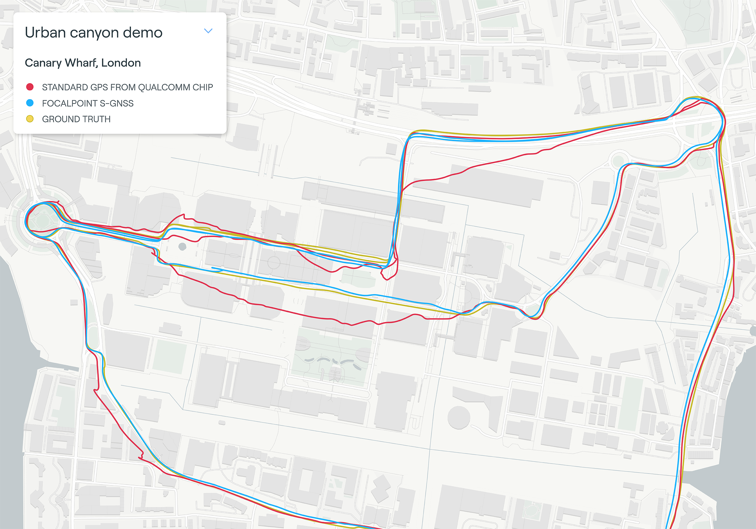
Map plot from live tests in London show the route of a vehicle driven through Canary Wharf. It shows the difference between the position provided by a standard smartphone GNSS chip (red line) and the same data run through Focal Point Positioning’s Supercorrelation software (blue line). (Image: u-blox)
U-blox has signed a deal with the award-winning U.K.-based technology company Focal Point Positioning to integrate technology that will improve the accuracy and reliability of GNSS devices. Focal Point’s Supercorrelation technology enhances positioning performance and security for applications such as smart cities, location-secure internet of things (IoT) and health and fitness wearables.
The patented Supercorrelation technology solves a critical weakness in GNSS caused by multipath interference. Multipath interference occurs when satellite signals bounce off buildings and landmarks, causing GNSS receivers to provide degraded positioning outputs.
The result for users is that the blue dot on their phone or device may be in the wrong place, moving in the wrong direction, or may have a large error ellipse. For autonomous vehicles it could lead to positioning errors that place the vehicle in the wrong lane or worse.
FocalPoint’s Supercorrelation technology uses software to detect and reject reflected signals, resulting in an improvement in the performance of GNSS devices without the need for additional hardware or applications. Supercorrelation also helps with the detection and rejection of GNSS spoofing signals — an increasing concern for autonomous vehicles, ships, and aviation.
“We are tremendously excited to be working alongside a market leader such as u-blox, our mission is to improve every positioning system on the planet and we have taken a giant step forward in that vision with this deal,” said Focal Point Positioning CEO Ramsey Faragher. “Positioning systems are so critical to our world, and we look forward to seeing the next generation of products and services that will be enabled by this higher level of accuracy, reliability and security.”
u-blox CEO Thomas Seiler commented, “The addition of Supercorrelation technology into our latest GNSS platforms is part of our continuing focus on low power consumption, higher accuracy and security for automotive, industrial, and wearable GNSS applications.”
The European Space Agency (ESA) has launched a call for proposals to demonstrate the capabilities of new 5G cellular networks to support positioning and timing applications to complement satellite navigation.
5G will bring higher speed, larger traffic capacity and ultra low-latency (or signal delay) communications. 5G will also usher in a range of new possibilities for positioning, navigation and timing (PNT).
ESA is inviting proposals to implement pilot projects to demonstrate the viability of 5G PNT solutions in a number of use cases:
Indoor PNT for Industry 4.0, as needed to support the operations of smart warehouses and factories or smart city applications requiring transition from indoor to outdoor environments.
Outdoor applications where a robust back-up to satellite navigation is essential to meet safety requirements, such as autonomous driving or drone navigation.
Applications where robust time and frequency synchronization is necessary, both in outdoor as well as indoor environments, like smart energy grids or the 5G networks themselves.
5G networks will allow new types of measurements made possible by advanced antennas and by new positioning signals at higher frequencies, at both base stations and the user receivers. 5G networks will also bring enhanced connectivity to improve cloud-based positioning applications and value-added services.
While satellite navigation works optimally in outdoor environments with a wide view of the sky, 5G PNT has the potential to bring PNT to deep urban canyons in high-rise city centers and indoor warehouses, wherever 5G networks are deployed.
The combination of satellite navigation and 5G brings the promise of high performance, secure and resilient PNT services, as well as a seamless application of PNT applications from outdoor to indoor environments and from rural to urban areas, ESA said.
This call for ideas is supported through ESA’s Navigation Innovation and Support Programme (NAVISP), working with European industry and academia to develop innovative navigation technology.
Webinar on PNT 5G
To support the call, an information webinar is being held on 21 October, in which the various PNT 5G use cases will be presented by key speakers from each sector. Details of the call and how to apply will also be presented by ESA.
A networking platform has also been established to allow webinar participants and general stakeholders interested in the call to get in touch and discuss possible cooperation. This platform will be kept open during the entire period of the call’s duration.
For more information on the call and the agenda of the webinar visit ESA’s NAVISP website.
To register for the webinar and the networking platform, click here.
The collaboration will provide designers with a power-efficient, high-accuracy GPS solution for battery-operated devices without the additional cost of a dedicated GNSS chip.
“Today’s advanced navigation systems are facing unique challenges when being implemented in power-constrained IoT devices,” said Ambroise Popper, CEO at Nestwave. “By combining Nestwave’s low-power geolocation software with Synopsys’ efficient ARC IoT Communications IP Subsystem, we can deliver a geolocation solution that offers greater accuracy, lower power consumption, and lower cost compared to existing GNSS solutions.”
Ultra-low bandwith IoT applications
The ARC IoT Communications IP Subsystem is an integrated hardware and software solution that combines Synopsys’ DSP-enhanced ARC EM9D processor, hardware accelerators, dedicated peripherals and RF interface to deliver efficient DSP performance for ultra-low bandwidth IoT applications.
Nestwave’s GNSS solution takes advantage of the ARC EM9D processor’s efficient DSP capabilities and ability to add dedicated hardware accelerators or custom instructions using APEX technology to reduce frequency requirements, giving customers additional performance bandwidth.
The ARC EM9D processor is supported by the MetaWare Toolkit, which includes a rich library of DSP functions, allowing software engineers to rapidly implement algorithms from standard DSP building blocks.
Geolocation for emerging applications
Nestwave has developed an ultra-low power, advanced GNSS solution for use in IoT applications. When integrated with an IoT modem such as NB-IoT, Cat M1, LoRa or Sigfox, the solution offers low-cost geolocation for emerging applications such as asset tracking, smart factories, and smart cities, without the need for an external GNSS chip.
“Emerging IoT applications are demanding geolocation functionality with high-accuracy and ultra-low power consumption,” said John Koeter, senior vice president of marketing and strategy for IP at Synopsys. “The combination of Synopsys’ ARC IoT Communications IP Subsystem with Nestwave’s GNSS technology will help designers significantly improve geolocation performance, reduce frequency requirements and lower overall power consumption for battery-powered IoT applications.”
By David Zilkoski, contributing editor, survey scene
David B. Zilkoski
I attended The Ohio State University (OSU) to obtain my graduate degree in Geodetic Science in 1979. Therefore, I will admit that I am a little biased — once a geodesist, always a geodesist. The basic definition of geodesy is the applied science for determining the size and shape of the Earth, designing and realizing reference frames, and determining where you (and anything else) is on the Earth.
In OSU’s geodesy heyday (1960–1990s), many Americans trained were sent by federal agencies: National Geospatial-Intelligence Agency (NGA), NOAA/National Geodetic Survey (NGS), USGS, Army, Navy and Air Force. During the 1970s, NGS was sending two employees back to school every year. These agencies needed geodesists because they were undertaking major projects such as NGS’ to readjust the U.S. national horizontal (NAD83) and vertical geodetic (NAVD88) networks.
I was one of the employees that NGS sent to OSU to be trained to support the NAD83 and NAVD88.
The advancements in satellites and computers have enabled geodesy to expand into many different disciplines. Geodetic science and technology now underpin many sciences, large areas of engineering (such as driverless vehicles and drones), navigation, precision agriculture, smart cities and location-based services. Geodesy is actually more important than ever.
Today, the environment is different. U.S. federal agencies still need geodesists for developing enhanced and refined geodetic models and tools. However, major U.S. companies, such as Google and FedEx, as well as the automobile industry, precision farming companies and mining companies also need more accurate geodetic models, tools and algorithms. Therefore, these companies also need trained geodesists to perform important research on topics that address their specific geodetic requirements.
Today, OSU’s Geodesy Department is training very few American citizens. As the U.S. moves toward achieving geodetic-grade positioning in real-time in support of new applications such as driverless vehicles and drones, the number of trained geodesists should be increasing, not decreasing [Note: In 1990, there were 92 geodetic science graduate students. In 2019, there were 25; only three were U.S. citizens]. OSU and other universities need to educate and train the next generation of the nation’s scientific workforce of highly skilled research geodetic scientists that will expand industry’s research expertise.
The shortage of American geodesists poses a significant economic risk for the U.S. Europe and China train many more geodesists than the US. There are very few geodetic science programs in the U.S. today, and education in geodetic proficiencies has been fragmented. The OSU graduate program is one of few surviving geodetic science programs.
Users of geodetic products and services need to support geodetic departments in universities so that U.S. geodesy programs can grow to meet the geospatial demands of the future. The geospatial component of the economy is worth about $500 billion/year. So why are we allowing its foundational discipline to shrink in this country?
Indoor location platform provides municipalities with emergency response and public safety solutions on existing Wi-Fi networks
InnerSpace, a Toronto-based company, is offering its Wi-Fi-based indoor location intelligence platform to support all levels of government. The platform analyzes patterns and movement in public spaces using existing Wi-Fi networks.
The platform is suitable for understanding the movement of people inside public spaces and can support emergency response strategies, social distancing programs and help smart cities implement effective security and public safety measures.
“In response to the global COVID-19 pandemic, we have accelerated the delivery of our public safety solution inFORCE,” said James Wu, CEO, InnerSpace. “Our platform processes RSSI [received signal strength indication] data in real time and returns the industry’s most accurate location data available today. By using public Wi-Fi access points, municipalities have a way to quickly roll out new solutions at city-wide scale.”
InnerSpace inFORCE was selected in a competitive process by the U.S. Department of Homeland Security, for its ability to use Wi-Fi to locate citizens and track emergency responders in an active shooter scenario.
The same platform can be used in a wide variety of emergency situations such as the current COVID-19 pandemic. In addition to the company’s tracking capabilities, it’s analytics dashboard gives public safety offices an unprecedented view into how people leverage public spaces.
“In times of emergency, it is reasonable to prioritize safety and public health to minimize the loss of human life,” said Cerys Goodall, president and COO, InnerSpace. “By providing municipalities with a system that can deliver line-of-sight into how people move in public spaces, we can inform response strategies, improve rescue efforts, and create an infrastructure to support better outcomes.”
InnerSpace inFORCE ingests RSSI data and returns accurate anonymous indoor locations. The information can be connected directly into emergency response communications systems, building management and security systems, or analyzed by InnerSpace to identify critical patterns and trends in people’s movements.
Rooftop view of the central parts of Aarhus with the harbor area and the sea in the background. (Photo: DTU Space)
A testbed in an active urban center can show real-world effects on GNSS as an aid for developing autonomous systems for green mobility, smart-city applications or transportation, to name a few.
Sited in Denmark, the 600-square-kilometer Testbed in Aarhus for Precision Positioning and Autonomous Systems (TAPAS) covers both a densely populated city center and suburbs, a large industrial harbor and parts of Aarhus Bay. Aarhus is the second largest city in Denmark with a population of 350,000 people.
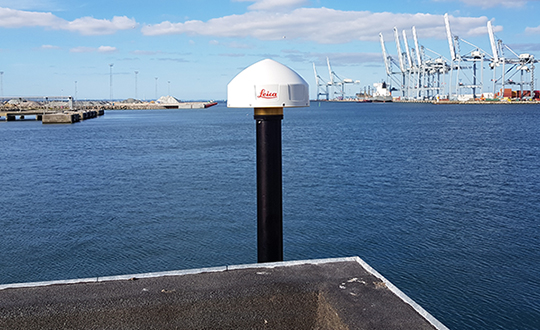
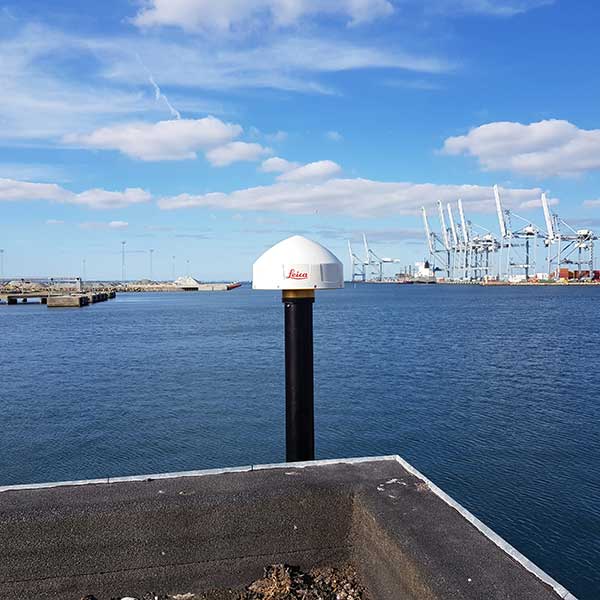
The GNSS antenna at TAPAS station TA01. (Photo: DTU Space)
Based on RTK methodology, TAPAS is a sound ground-based testbed to support, test and validate technological developments with a need for fast, efficient, flexible and reliable precision positioning. It is designed as a geodetic innovation platform, with both physical and virtual networks providing positioning to the centimeter (cm) level.
Autonomous systems within transportation, agriculture and environmental monitoring constitute a large growth area for businesses and governments. Automated vehicles, drones and vessels are linked closely to geodetic infrastructure and communications networks such as 5G. TAPAS provides developers in these fields with opportunities to observe GNSS in urban canyons and under canopies, as well as challenges for coastal marine applications. The testbed is available for third-party research projects, and testing of ideas, initiatives and concrete prototypes.
TAPAS is fully funded and owned by the Danish Agency for Data Supply and Efficiency (SDFE), the Danish agency for geodesy and geographical data. TAPAS is developed by the National Space Institute at the Technical University of Denmark (DTU Space), and is supported by the city of Aarhus. The TAPAS testbed was established partly because of Denmark’s National Space Strategy, which points to the new technological development within positioning, as well as possibilities for use of Galileo, the European GNSS, to the benefit of as many citizens as possible.
In this article, we review the TAPAS testbed, including design and installation of the GNSS reference stations and the data-processing center, as well as initial performance testing carried out by DTU Space.
Network of GNSS Reference Stations
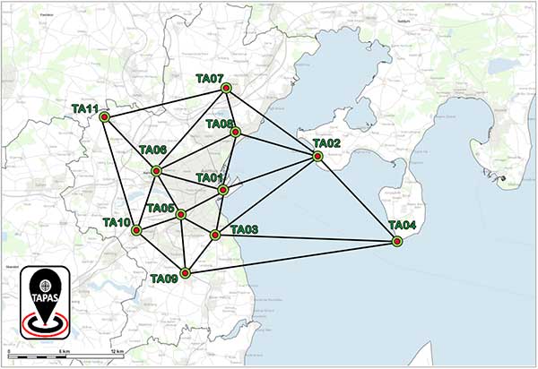
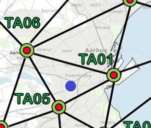
The network of TAPAS stations in and around the city of Aarhus in Denmark. (Map: DTU Space)
The basic component of TAPAS is high-accuracy carrier-phase-based GNSS positioning using the network RTK methodology, which can provide real-time position accuracies for the end user down to the cm level.Essentially, TAPAS is based on a network of 11 GNSS reference stations as well as data communication infrastructure, a central processing facility with a data server, processing software and data storage.
TAPAS was designed to provide real-time position uncertainties for objects in motion within 1 cm in three dimensions (1 cubic cm), for end users with modern GNSS equipment. A dense network of GNSS reference stations was originally designed with stations 5 km apart in the city center and up to 10 km apart in the suburbs.
Because suitable locations had to be found, in the final network distances range from 4.1 km to 22.3 km, with the longest distances across the water to station TA04 (see the network plot in the graphic above).
Stations TA01, TA03, TA05, TA06 and TA08 are in the city center. Stations TA02 and TA04 are across Aarhus Bay, ensuring coverage for marine applications and contributing to more robust positioning near the sea and in the harbor area around station TA01.
TAPAS Stations
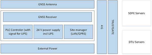
The TAPAS GNSS reference stations are equipped with the newest generation of GNSS receivers and antennas capable of tracking all available signals from the GPS, GLONASS, Galileo and BeiDou systems. The stations also have an antenna splitter, power supply, fuse box, programmable logic controller (PLC) for monitoring and control, trustgate, modem and uninterruptible power supply with battery pack (Figure 1). All units were integrated in the cabinets and tested in the lab before installation The stations are modular and flexible for future iterations and updates.
The receivers can be accessed remotely via a VPN line to a web interface for monitoring, changing settings or firmware updates. All TAPAS stations transmit data to servers at DTU Space where the data is used for estimation of RTK corrections. Also, data is transmitted to servers at the SDFE for storage and backup (Figure 1).
Figure 1. Design schematics of the TAPAS stations. (Image: DTU Space)
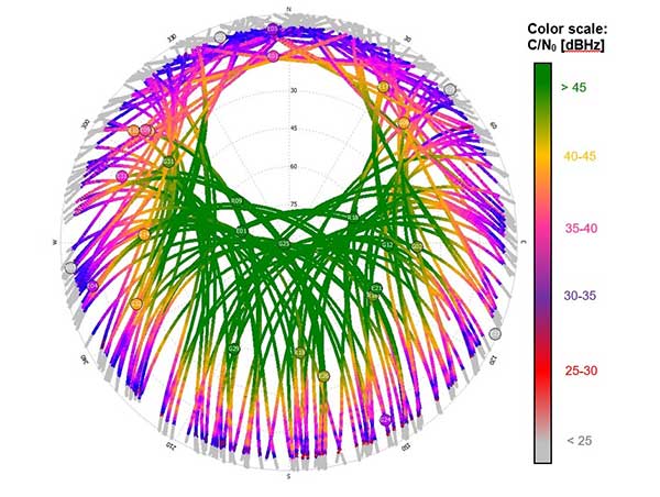
After installation in the fall of 2018, GNSS data quality was verified for each station by estimating preliminary positions and analyzing data quality. Also, signal strength as given by the carrier to noise ratio (C/N0) of the received signals was analyzed and plotted with 24 hours of data from each of the stations (Figure 2).
Network Real-Time Kinematic (RTK)
Data from the TAPAS stations streams in real time to the Central Processing Facility (CPF) operated at a dedicated server at DTU Space in Lyngby, North of Copenhagen. The GNSS observations are processed using the GNSMART 2 software from Geo++, where corrections for network RTK positioning are estimated. The corrections are estimates for errors affecting the GNSS positioning, such as inaccuracies in satellite positions and clock drift parameters as well as ionospheric and tropospheric effects. The dense network of reference stations in TAPAS will assure that corrections for the atmospheric effects will be of very high quality.
For estimation of the RTK corrections, standard software settings are used. All corrections are estimated by a state space representation (SSR) technique, where error sources are modeled individually. This means TAPAS can deliver both RTK corrections and corrections for precise point positioning (PPP).
TAPAS corrections are generated in the RTCM format and output using the NTRIP protocol. Registered users can access the corrections through the internet via an NTRIP caster. On the user side, the TAPAS corrections are applied in the positioning process of a GNSS receiver. To make full use of the TAPAS data, user equipment should be capable of tracking carrier-phase-based GNSS data and applying the TAPAS correction data supplied in the RTCM version 3.x format.
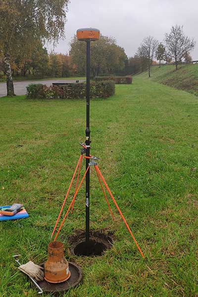
An example of a use of TAPAS is provided in the photo in Figure 9 below where the authors of this article tested the position accuracy of TAPAS for a typical land surveying task, using a Septentrio Altus APS3G receiver with an allegro2 controller unit for RTK positioning. The user’s GNSS equipment can, however, be many other different types and makes of GNSS antennas and receivers, and the equipment can be installed on many different platforms for instance in vehicles, on drones, in robots etc.
Geodetic Basis
When determining positions with uncertainties at the 1-cm level, it is important to be aware of the geodetic reference frame used for the positioning. In this case, coordinates for the TAPAS stations have been estimated by DTU Space, using Bernese GNSS software, in the national Danish reference frame which is a realization of the European Terrestrial Reference System (ETRS).
When applying corrections from the TAPAS caster in the positioning calculations at the user side, positions will be obtained within the same reference frame (coordinate system). In this case, where the national geodetic reference frame is used, this means that the user will obtain positions compliant with maps, charts and other types of geodata geo-referenced in the same coordinate system.
For 3D positioning, the Danish geoid model must be applied on the user side to obtain heights relative to mean sea level in the national Danish Vertical Reference (DVR90).
It is possible to configure the setup of the central processing facility using another reference frame for TAPAS given that precise coordinates for the TAPAS stations can be provided in the given reference frame. Future work with TAPAS can involve the use of dynamic geodetic reference frames and transmission of coordinate transformation parameters to the users.
Performance Testing
After the stations were installed, DTU Space conducted performance testing, including testing data communication between the TAPAS stations and the TAPAS server, analyses of data completeness from the TAPAS stations, and field tests carried out after the network RTK processing had become sufficiently stable.
Performance test in static mode. In February 2019, a static mode test took place in a park-like area within the three innermost stations. Two different high-accuracy survey-grade RTK-receivers were used for the field test. RTK positions were estimated at 1 Hz for 30 minutes. For each minute, an average position was calculated based on the 60 observations, and for each of the minute-bins the standard deviation with respect to the reference position was computed.
Test location indicated with purple circle in the network plot. (Image: DTU Space)
Altus APS3G unit mounted at the test location. (Photo: DTU Space)
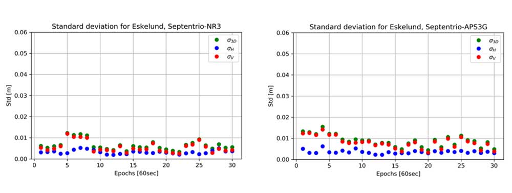
The results are shown in the plots below, where standard deviations are provided for each epoch (i.e., for each bin of 60 seconds).
Standard deviation in meter for each 60 second with GNSS receiver Altus NR3 (left) and Altus APS3G (right). Results provided in meter. (Images: DTU Space)
In the plots, results are provided for the vertical (red), the horizontal (blue) and the 3D position (green). Results of using the two different receivers are comparable, and focusing on the 3D solutions the largest standard deviation is 1.6 cm which is for the fourth epoch with receiver APS3G. Most of the 3D results shown in the plots are better than 1 cm.
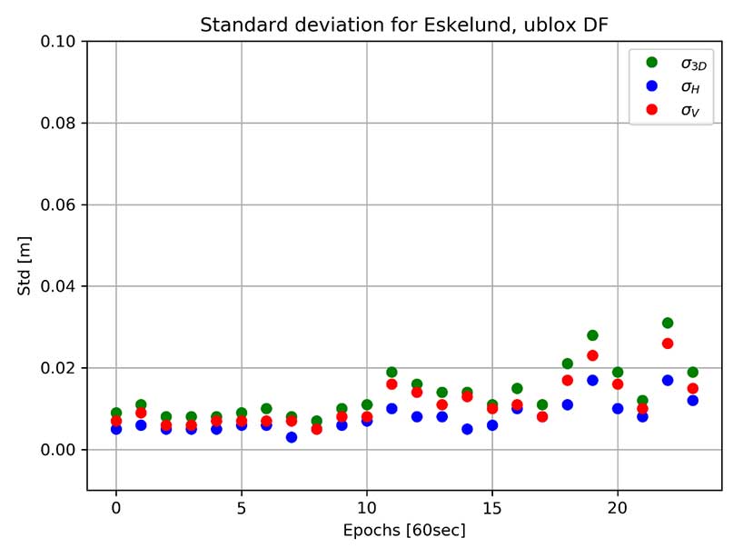
The same test was carried out using a dual-frequency non-survey-grade receiver developed for machine control and autonomous vehicle applications. This receiver was connected to the same antenna mounted on a tripod. Results of using this receiver in static mode are shown in the plot below. In this case, the 3D results are all better than 3.1 cm, and many of the 3D results are better than 1 cm in this open test area.
Standard deviation for each 60 second with GNSS receiver u-blox F9P dual frequency (DF). Results provided in meter. (Image: DTU Space)
Performance test in kinematic mode. In the same area used for the static test, a kinematic test was carried out with the same three receivers.
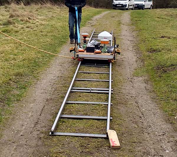
The test was performed using a camera dolly and by placing approximately 10 m of rail on the ground. The camera dolly was pulled back and forth along the rail, a setup that provided a stable trajectory for testing positioning performance while the GNSS antennas were moved slowly and smoothly. A rigid bench, where the GNSS antennas could be mounted, was constructed and installed on the dolly. The three GNSS receivers with antennas were mounted on the bench, and the dolly was pulled back and forth along the tracks 10 times.
Kinematic Test: Camera dolly with GNSS equipment pulled along tracks. (Photo: DTU Space)
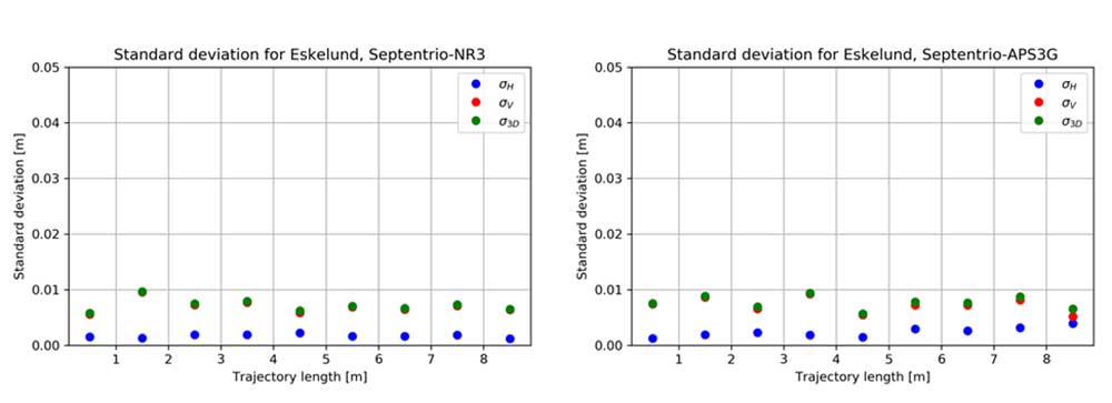
For each 1-meter section of track, the standard deviation of the differences with respect to the reference trajectory of the 10 repetitions was calculated. Results for the two survey-grade receivers are shown in the plots in Figure 3. All of the 3D standard deviations are better than 1 cm for both survey-grade receivers.
Figure 3. Kinematic test results are provided for the vertical (red), horizontal (blue) and 3D (green) positions. (Image: DTU Space)
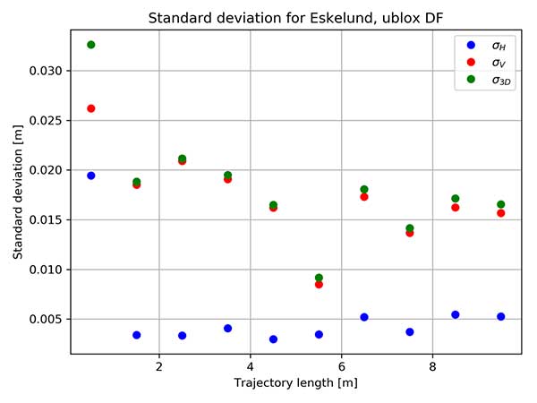
The non-survey-grade dual-frequency receiver also was mounted on the test bench, and the results of using this receiver are shown in the plot below. With this receiver, the 3D results are below 2.1 cm for all sections of the trajectory, except for the first meter, a deviation that may have been caused by issues with initialization of the test.
Binned standard deviation of 10 repetitions with GNSS receiver u-blox F9P dual frequency (DF). Results provided in meter. (Image: DTU Space)
These tests show that it is possible when using TAPAS to obtain position solutions at the cm-level in open areas in both static and kinematic mode.
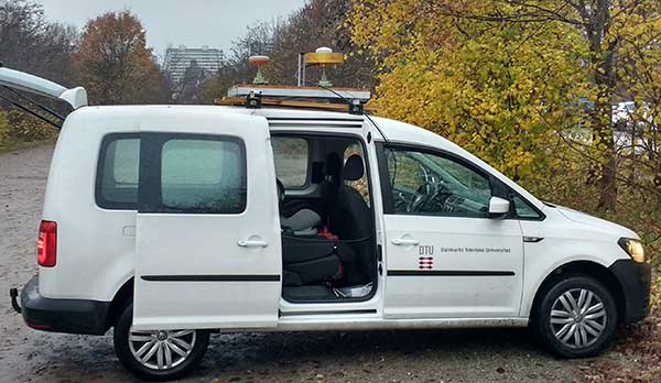
Performance test in dynamic mode. In November 2019, DTU Space carried out a performance test of TAPAS in dynamic mode, using a car with roof-mounted GNSS equipment. The car was driven within the TAPAS coverage area, passing through urban canyons, open streets and the harbor area. During the test, the car drove in normal Aarhus traffic, at speeds varying from zero at traffic lights up to 60 km/h on the wider roads leading into the city center.
Four different receivers were strapped in the car and connected to either a small patch antenna or a survey-grade antenna mounted on the roof. A survey-grade receiver was mounted on the roof.
Three different GNSS antennas mounted on the roof of the car used for dynamic testing. (Photo: DTU Space)
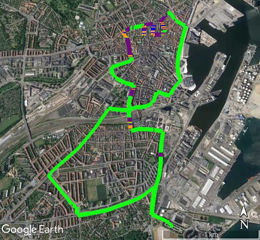
Data from the receiver was converted to KML files, which can be used with Google Earth to illustrate the quality of the positioning obtained during the drives through the city. The plot in Figure 4 shows the quality of the position solution. The best quality is obtained when the ambiguities are fixed, such as an RTK fixed solution at the cm level (green). The second-best quality is with ambiguities estimated to float values, such as an RTK float solution at the dm level (purple). Orange shows differential position solutions at the meter level when corrections for the carrier-phase data have not been obtained. Finally, a few positions were stand-alone GNSS solutions when no aiding from TAPAS was applied in the roving GNSS receiver (blue).
Figure 4. Quality of RTK positions obtained during one drive through the City of Aarhus. (Map data: Google, TerraMetrics)Photo:
The plot clearly shows, as expected, that the quality of the positions determined by the survey-grade receiver in the car is good most of the time. But it suffers in areas with narrow streets aligned with buildings or trees.
These results do not tell the actual uncertainty of the position solutions. But GNSS carrier-phase data collected with one of the receivers in the car during the drive will be post processed to serve as a reference trajectory. Upcoming analyses of the data will then reveal the uncertainty of the positions determined in real time as compared to the post-processed reference trajectory.
Test Conclusion. After the field tests, we conclude that the TAPAS testbed is able to provide correction data that makes it possible to perform GNSS-based positioning in real time in both static and dynamic mode with position uncertainties at the cm-level. Further, as we analyze the test data thoroughly, TAPAS will be able to set a tone for new research. For instance, the plot in Figure 4 provides a foundation for testing assistance procedures to gain better coverage in the most densely built areas. In this way, TAPAS will aid research into feasible infrastructure for the technologies of tomorrow, such as autonomous driving.
Outlook and Future Work
Because TAPAS is not commercial, it is possible, upon agreement with the SDFE, to make changes to the system to adapt to specific testing or development needs. Examples are removing data from some stations in the estimation of RTK correction data, installing an extra receiver in one or more stations using the antenna splitters, or making changes to the settings in data processing on the TAPAS server for shorter time intervals.
At DTU Space, plans for the testbed include further development of software for ionosphere and integrity monitoring. The station receivers can estimate total electron content (TEC) along the GNSS signal path in Earth’s atmosphere, as well as indices for ionospheric scintillation. DTU Space is researching using this output for an ionosphere monitoring service and to develop it into an integrity monitoring service for GNSS users.
Upcoming additions to the RTCM data format will support more advanced modeling of the effects of the ionosphere and troposphere, and this will allow for full benefit of the TAPAS SSR network corrections. Research on such models to be applied on the server side, as well as on the user side, will be carried out by DTU Space and tested with TAPAS as a contribution towards the integration, or hybridising, of PPP and RTK. This is also referred to as PPP-RTK positioning which is expected to be especially useful for mass market applications such as autonomous driving. When implemented in TAPAS, such solution may effectively increase the number of simultaneous users as well as use-cases for TAPAS.
TAPAS provides many opportunities for testing precision or high-accuracy applications, such as autonomous vehicles, vessels, drones and robots; location-based services requiring high accuracy on various digital platforms; and solutions for a more digitized and intelligent city environment through smart-city and green mobility initiatives.
TAPAS is prepared for the implementation of the coming 5G technologies, and station intercommunication capabilities enable testing of internet of things (IoT) technologies where precision positioning is part of the development. The testbed also provides an excellent environment for validation of new services such as the Galileo High Accuracy Service (HAS). Another area in which TAPAS can play an important role is verification and validation of future 5G-based positioning services.
The TAPAS testbed was developed with close cooperation between DTU Space and SDFE. SDFE contributors include Kristian Keller, Casper Jepsen, Henrik Olsen, Martin Skjold Grøntved, Brigitte Rosenkranz, Maria Rask Mylius and Søren Fauerholm Christensen. DTU Space contributers include Ole Bjerregaard Hansen, Finn Bo Madsen, Lars Stenseng, Daniel Haugård Olesen, Stefan Emil Steffensen, Thor Heine Snedker, Per Knudsen and Niels Andersen.
Manufacturers
The GNSS receivers at the TAPAS stations are Septentrio PolaRx5S, and the antennas are Leica AR20. For field testing, a Septentrio Altus NR3 receiver, a Septentrio Altus APS3G receiver and a u-blox ZED F9P dual-frequency receiver were used. The TAPAS station cabinets were assembled and mounted by Nordtec-Optomatic A/S. The TAPAS testbed software solution is based on the GNSMART 2 software package from Geo++ GmbH. Data analyses and processing has been carried out using the Septentrio SBF Analyser and SBF Converter, the RTKlib and the Bernese GNSS software.
Anna B. O. Jensen is senior advisor and team lead of the GNSS group at DTU Space in Denmark. She is also a part-time professor at KTH Royal Institute of Technology in Sweden.
Per Lundahl Thomsen is a chief consultant at DTU Space. He has many years of experience with management of space technology projects and is project manager for the TAPAS testbed.
Søren Skaarup Larsen is a Ph.D. student at DTU Space. Along with his GNSS studies, he runs the RTK-part of the TAPAS testbed.
Hyundai is the first Uber Elevate partner with manufacturing capabilities to mass produce Uber Air Taxis
Uber and Hyundai Motor Company announced at CES 2020 a new partnership to develop Uber Air Taxis for a future aerial ride-share network and unveiled a full-scale aircraft concept. Hyundai is the first automotive company to join the Uber Elevate initiative, bringing automotive-scale manufacturing capability and a track record of mass-producing electric vehicles.
CES 2020, the massive annual consumer electronics show, is taking place Jan. 7-10 in Las Vegas. Hyundai Motor’s innovative smart mobility solutions including UAM, PBV, Hub and more are showcased at Booth 5431 in the Las Vegas Convention Center North Hall.
The taxi concept was created in part through Uber’s open design process, a NASA-inspired approach that jump starts innovation by publicly releasing vehicle design concepts so any company can use them to innovate their air taxi models and engineering technologies.
In this partnership, Hyundai will produce and deploy the air vehicles, and Uber will provide airspace support services, connections to ground transportation, and customer interfaces through an aerial ride-share network. Both parties are collaborating on infrastructure concepts to support take-off and landing for this new class of vehicles.
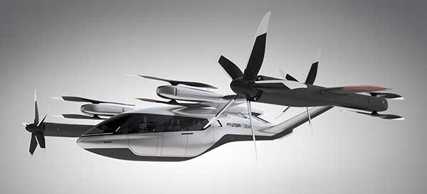
The SA-1 air taxi. (Photo: Uber/Hyundai)
“Our vision of urban air mobility will transform the concept of urban transportation,” said Jaiwon Shin, Executive Vice President and Head of Hyundai’s Urban Air Mobility (UAM) Division. “We expect UAM to vitalize urban communities and provide more quality time to people. We are confident that Uber Elevate is the right partner to make this innovative product readily available to as many customers as possible.”
“Hyundai is our first vehicle partner with experience of manufacturing passenger cars on a global scale. We believe Hyundai has the potential to build Uber Air vehicles at rates unseen in the current aerospace industry, producing high quality, reliable aircraft at high volumes to drive down passenger costs per trip. Combining Hyundai’s manufacturing muscle with Uber’s technology platform represents a giant leap forward for launching a vibrant air taxi network in the coming years,” said Eric Allison, head of Uber Elevate.
In preparation for this announcement, Hyundai worked with Uber Elevate to develop a PAV (personal air vehicle) model, S-A1, that uses innovative design processes to optimize electric vertical take-off and landing (eVTOL) aircraft for aerial ridesharing purposes. S-A1 previous eVTOL designs Uber Elevate has released in the following ways:
It is designed for a cruising speed up to 180 miles/hr (290 km/hr), a cruising altitude of around 1,000-2,000 feet (300 – 600 mt) above ground, and to fly trips up to 60 mile (100 km).
The Hyundai vehicle will be 100% electric, utilizing distributed electric propulsion and during peak hours will require about five to seven minutes for recharging.
Hyundai’s electric aircraft utilizes distributed electric propulsion, powering multiple rotors and propellers around the airframe to increase safety by decreasing any single point of failure. Having several, smaller rotors also reduces noise relative to large rotor helicopters with combustion engines, which is very important to cities.
The model is designed to take off vertically, transition to wing-borne lift in cruise, and then transition back to vertical flight to land.
The Hyundai vehicle will be piloted initially, but over time they will become autonomous.
The cabin is designed with four passenger seats, allowing riders to board and disembark easily and avoid the middle seat with enough space for a personal bag or backpack.
Ushering in the era of seamless mobility, Hyundai’s exploration of future urban transportation incorporates the electric PAV concept with a new ground transportation, the Purpose Built Vehicle (PBV) concept.
Hyundai’s vision for creating communities from future transit systems comes into focus with yet another new infrastructure concept, called the Hub. When many PBVs and PAVs are docked and connected to a Hub, they make a new public space where diverse groups of people can come together.