By Alexander Rügamer, Daniel Rubino, Xabier Zubizarreta, Wolfgang Felber, Fraunhofer IIS, and Jan Wendel and Daniel Pfaffelhuber, Airbus Defense and Space GmbH
This work presents a new secure localization method that can be used for UAVs to obtain a new level of protection against hostile and unauthorized UAVs. While non-spreading code-encrypted (SCE) GNSS devices can be blocked, authorized UAVs using this method have unrestricted access to the non-spoofable and trusted SCE GNSS. The proposed method is to store short sequences of SCE PRN code chips on the user receiver before the mission.
The Precalculate & Process architecture. (Images: Fraunhofer IIS)
These SCE PRN code chips allow the user receiver to calculate at pre-defined points in time a secure and trustable SCE PVT position. Since no communication channel is required, this method mitigates the risk that hostile forces may try to jam the UAV’s radio control. Moreover, radio silence can be realized, which is beneficial or even required for some missions.
No dedicated security module required on the user terminal, no SWaP problems, no keying issues, no handling of controlled items on user side, no need for a communication link giving rise to the availability and radio silence issues, and no security issues due to the short SCE PRN code chip sequences valid only for the limited mission duration and inside a limited area.
Potential target markets for this method are police and special forces and other authorized users which are allowed to use certain SCE GNSS and would like to equip their UAVs with a secure, unspoofable positioning solution. Check out more information here.
Regulus Cyber is showcasing its anti-spoofing GNSS receiver at the Consumer Electronics Show, being held Jan. 8-11 in Las Vegas.
Previously introduced in our Launchpad feature, the Regulus Cyber solves GNSS spoofing attacks that threaten the automotive, aviation, maritime and mobile industries with a unique technology applicable both as a fortified GNSS receiver, capable of detecting spoofing attacks, and at the chip level, allowing mobile phones, cars and internet of things (IoT) devices to receive GNSS spoofing protection for the first time, the company said.
The company was able to miniaturize its technology into a form factor that provides customers more flexibility with integration.
The Regulus Pyramid GNSS Receiver is a fully functional GNSS receiver, fortified with the spoofing detection capability. The receiver contains patented technology that enables it to differentiate between real GNSS signals and fake ones generated by an attacker.
The Pyramid GNSS receiver is a direct replacement to any automotive GNSS receiver. The upcoming chip-level technology offers both spoofing detection and spoofing mitigation to any GNSS-based device, including mobile phones, the company added.
The Spoofing Problem. Any vehicle guided by a GNSS system can be spoofed using open-source software and a software defined radio (SDR) legally purchased from Amazon for under $300. A spoofer can generate and transmit fake GNSS signals that can be used by the vehicle’s navigation system to calculate a false destination, directing the vehicle to an entirely different location, a potentially life-threatening hazard.
In addition, spoofing is a growing concern to any application or device that uses satellite positioning, navigation or time. While real attacks are expanding, anti-spoofing solutions remain a luxury that only high-end, defense markets can afford.
While current solutions are big, heavy and expensive, Pyramid GNSS offers industry-standard size and price. Industries such as automotive, aviation, maritime, and mobile phones can defend themselves against this sophisticated emerging threat, at an affordable price and relevant size, power consumption and weight, the company said.
“We designed our product to be a fraction of the size that is currently available on the market so that all types of companies – whether it is a car manufacturer or telecom provider relying on GNSS – can integrate it seamlessly,” said Yonatan Zur, CEO of Regulus Cyber. “GNSS spoofing will need to be a major security focus during 2019 since it leaves so many industries vulnerable to attacks.”
To meet Regulus Cyber at CES, visit booth #2602 at the Westgate.
Growing awareness of the vulnerabilities of GNSS signals — weak, unencrypted and easily jammed or spoofed — have made GNSS less important to steering the driverless vehicle. What’s up with that?
Extensive visual map databases are being created that, when coupled with cameras, radars and lidars on the vehicle and processed by artificial intelligence (AI) algorithms, enable the driverless car to be steered much the way humans drive. Pattern recognition processing in the vehicle allows it to “read” street signs and recognize landmarks, registering its position on the map.
This is the way a person drives in his or her home town, where they always know their orientation and don’t need GNSS. The AI processing “brain,” with access to huge map databases, either through local storage or a network connection, will always be in its familiar home environment: continuously knowing its own position and properly oriented for navigation.
So, will GNSS become unnecessary in the car of the future? Probably not.
First, no one method of navigation is foolproof, and today, GNSS is our primary method of navigating our cars. It is a cost-effective, accurate way of determining position in real time, and with the integration of inertial navigation sensors to handle cases when GNSS is intermittently unavailable, it is improving.
Second, it is not just the car itself that needs to know its location for navigation, but also others outside the car. Ride-sharing apps like Uber and Lyft, car-sharing, usage-based insurance apps, dynamic toll charging, and parking apps all depend on knowing where the car is at all times. GNSS offers sufficient accuracy for all these apps by providing location coordinates. Therefore, a GNSS receiver will most likely remain in the car.
The case for jamming and spoofing
Recall, however, that one of the weaknesses of GNSS is its open, unencrypted format. It is becoming increasingly easier to spoof these signals. Car-sharing, usage-based insurance and dynamic toll charging apps all create a monetary incentive for fraud that can be implemented with a spoofer. For example, a car in a car-sharing network can report a fake position indicating that it is safely parked in a secure area — while in reality, a thief is busy driving it away.
(Image: Orolia)
Let’s assume that all wireless connections to and from the car are secure. This is a reasonable assumption, although recently there have been demonstrations of carjacking via unsecure remote links. Standard SSL encryption, similar to what is used to enter credit card information on the internet, works well here. We have both the awareness and the technology now to prevent such carjackings from ever reoccurring.
However, even if communication links are secure, a GNSS spoofer in the car can fool the GNSS receiver into reporting a fake “safe” position right as it is being stolen. The same is true for insurance or toll apps. And the fraud does not have to be sophisticated. A simple, low-cost jammer can deny proper position just long enough to skirt payment. A secure location method is needed.
Other signals for localization
What would an ideal signal for localizing a driverless car look like?
It needs to be much stronger than GNSS so it is not easily jammed.
It needs to be encrypted so it cannot be spoofed.
It must be ubiquitous, available worldwide.
It must be reliable and robust — with 99.999% availability or better.
It must be practical and priced for the mass-market automotive application.
Though accuracy is always important, the signal used for localization does not have to be as accurate as GNSS is today. Accuracy to 10s of meters is sufficient for all these applications needing fraud protection since it would not be used for steering the car, but rather, only localization. It can also be used in tandem with GNSS to authenticate a reported position when a GNSS signal is available.
Such a signal is available today, worldwide: STL (Satellite Time and Location). Carried on the Iridium satellites, it is a special purpose signal that is more than 30 dB stronger than GNSS and encrypted for anti-spoof protection. Decoding of this signal is available via a subscription model to users.
Here’s how it would work using a car-sharing example. A group of people subscribe to a car-sharing service that provides X number of cars to serve Y number of people, where X is less than Y. The service optimally schedules people when and where a car will be available. The service provider needs to know the whereabouts of the cars at all times to maximize utilization of the fleet, so every car has a GNSS receiver in it.
But to ensure the authenticity of these reports, they also have a secure localization receiver. This receiver is assigned a unique ID that is authorized to decode the encrypted signal. (Eventually, we expect this receiver and GNSS to converge into one device much the way multi-GNSS receivers operate today).
If a position report does not agree with the authentic localization report, the fleet manager can act to recover the car immediately. Insurance providers who cover secure localization-equipped cars would also give preferential rates as an anti-theft device.
(Image: Pavel Vinnik/Shutterstock.com)
Could PRS do it?
The new Public Regulated Service (PRS) from Galileo is encrypted and could provide a similar level of authentication protection, if made available. However, it is still a weak GNSS signal that can easily be jammed. Of course, any signal can be jammed, even one that is a thousand times stronger than GNSS.
However, given the robust nature of a very strong signal, the managing system that is monitoring the cars — the insurance, toll or car-sharing system, for example — can alarm upon the loss of positioning information. Such alarms on a GNSS-only car would be frequent and often erroneous due to simple fades, yielding so many false alarms that it would render the monitoring system useless. But a loss of both the strong localization signal and GNSS would likely be considered suspicious and result in a valid alarm.
GNSS navigation is truly one of the great advances of the modern era, giving us precise time and location for any place in the world. Its two major weaknesses — that it is easy to jam and spoof — can be overcome by augmenting it with other stronger encrypted signals, such as STL, providing robust jam-resistance and positive authentication.
Overview of the main signal design aspects relevant for authentication at the spreading code level. (Image: Authors)
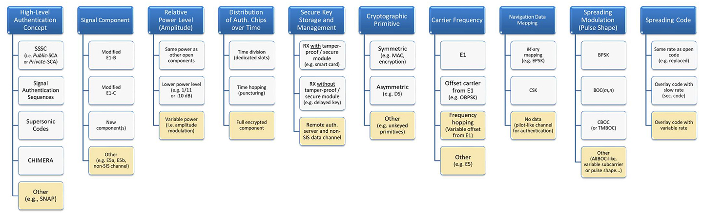
SNAP: An Authentication Concept for the Galileo Open Service
By Beatrice Motella and Davide Margaria, Istituto Superiore Mario Boella
and Matteo Paonni/European Commission
Presented at ION/IEEE/PLANS 2018
The design of a solution for the authentication of both navigation data bits and spreading code chips — Spreading Code and Navigation data-based Authentication Proposal (SNAP) — and suitable for the evolution of the Galileo E1 Open Service (OS) signal is presented in this paper. Though the technique is innovative and able to achieve predefined authentication performance, it exploits the structure of the legacy Galileo signal and the characteristics of the OS Navigation Message Authentication (NMA) that will be transmitted starting in 2018. A detailed overview of the open choices for the design of signal components dedicated to authentication is provided, together with an analysis of signal parameters definition. A possible implementation option of the SNAP solution is also presented.
After investigating the performance of the solution under different families of spoofing attacks, a trade-off analysis addressed to the definition of the solution parameters is presented, followed by a possible implementation of the SNAP concept, referred to as working point.
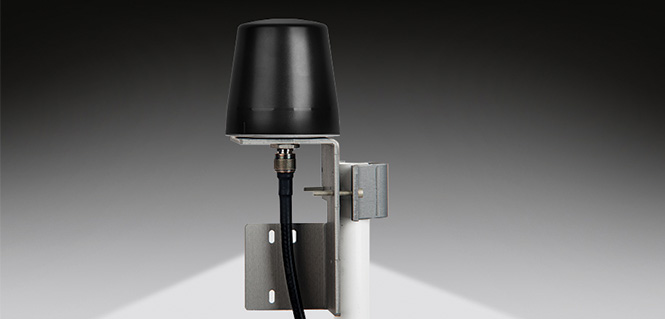
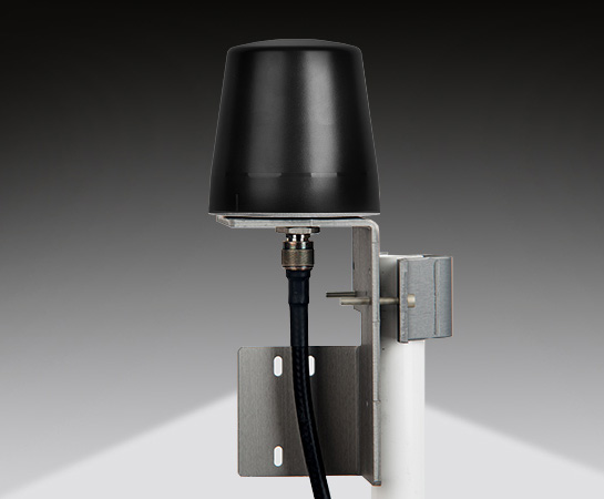
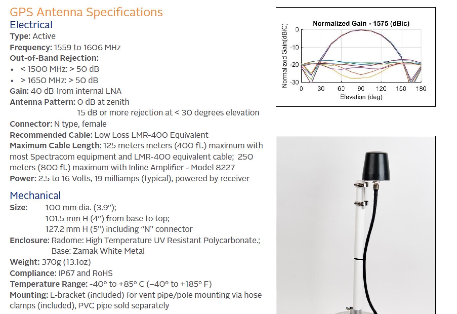
Designed primarily for applications such as homeland security, Spectracom’s 8230AJ antenna provides protection in high-interference environments where additional resilience is needed, such as communications networks, financial systems and power grids, the company said.
Orolia, through its Spectracom brand, said the antenna, Model 8230AJ, is a drop-in replacement for the company’s Model 8230. Its conical antenna pattern rejects interference from the horizon and is simple to mount using the same pipe supports, without new cabling. All that is required is a new bracket.
“Model 8230AJ is a high gain (40 dB) GNSS outdoor antenna covering GPS L1, GLONASS L1, BeiDou B1, Galileo E1, and QZSS L1,” said David Sohn, product manager at Spectracom. “It uses a three-stage low noise amplifier, a mid-section SAW, and a tight pre-filter to protect against saturation by high level sub-harmonics and L-band signals. It is designed especially for harsh environments, is IP67 rated, and improves resilience and protects against jamming and spoofing.”
According to the company, the AJ antenna rejects signals for the lower elevation angles – where most interference comes from – and only receives signals from the higher elevation angles where the satellites are. While this reduces the number of satellites the receiver will see, for timing applications only a few satellites are needed. Moreover, with multi-constellation receivers, an increasing number of satellites are available.
With the increasing prevalence of jamming and spoofing, industries with critical infrastructure must take measures against interference. GPS and GNSS in general have well-known vulnerabilities and limitations that require protection and mitigation: the signals are easily disrupted by unintentional interference from radio transmitters, they are extremely weak, cannot penetrate buildings and can easily be jammed, and civilian signals are not encrypted and can easily be spoofed.
The new anti-jam outdoor antenna is appropriate for anyone who uses a time server, including Spectracom customers who own a SecureSync, VersaSync or Netclock, according to the company.
By Yongqiang Wang and Aranya Chakrabortty, Clemson University /
IEEE Power and Energy Society General Meeting, September 2017
Phasor Measurement Units (PMU) are playing an increasingly important role in wide-area monitoring and control of power systems. PMUs allow synchronous real-time measurements of voltage, phase angle and frequency from multiple remote locations in the grid, enabled by their ability to align to GPS clocks. Given that this ability is vulnerable to GPS spoofing attacks, which have been confirmed easy to launch, this paper proposes a distributed real-time wide-area oscillation estimation approach that is robust to GPS spoofing on PMUs and their associated Phasor Data Concentrators (PDCs). The approach employs the idea of checking update consistency across distributed nodes and can tolerate up to one third of compromised nodes. Numerical simulations confirmed the effectiveness of the proposed approach.
The lead author, an assistant professor of electrical and computer engineering at Clemson, leads a team that received $1 million from the National Science Foundation to fortify computers and devices against cyberattacks associated with timekeeping. “We want to provide secure timing solutions by securing the two most commonly used time distribution approaches,GPS receivers and NTP.”
Two methods of spoofer detection, the identification and sourcing of false GNSS signals, have been released by Javad GNSS, using features available for all of its OEM GNSS boards.
Spoofer detection and alarm. This feature then identifies and isolates the spoofer signal, ignores it, and provides a position solution using only valid satellite signals.
Determination of the direction from which the spoofing signals emanate. This can aid in tracking down the actual spoofing source.
Spoofer Detection
With 864 channels and roughly 130,000 quick-acquisition correlators, the Javad GNSS Triumph chip can assign more than one channel to each GNSS satellite, in order to find all the signals that are transmitted with that satellite’s PRN code. If the chip detects more than one reasonable and consistent correlation peak for any PRN code, it concludes that spoofing is present and can the proceed to identify the spoofed signals.
In this case, it uses the position solution provided by all other clean signals (L1, L2, L5, and so on, from all GNSS constellations — GPS, GLONASS, Galileo, Beidou, and mroe) to identify the spoofer signal and use the real satellite measurement. If all GNSS signals are spoofed or jammed, then the system issues an alarm, directing the user to ignore GNSS and use other sensors in an integrated system.
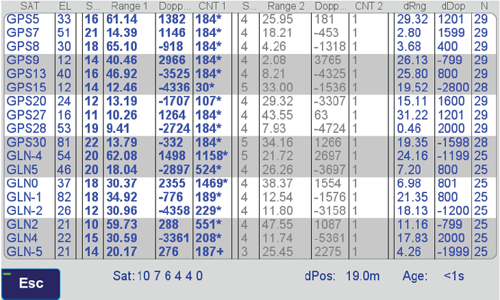
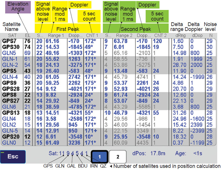
Satellite and Spoofer Peaks
The figure below shows an example of a spoofer signal and a real satellite signal received at a GNSS receiver. These screenshots are from a real spoofer in a large city. The bold numbers are for the detected peaks. The gray numbers represent highest noise, not a consistent peak. A “*” symbol next to the CNT numbers indicate that signal is used in position calculation. Each CNT count represent about 5 seconds of continuous peak tracking.
The first screenshot shows no spoofing is present. The second shows that all GPS satellites are being spoofed.
No spoofer. Only one reasonable peak for each satellite. (Table: Javad GNSS)Table: Javad GNSS
In the above screenshot all GPS satellites have two peaks and all are spoofed. We were able to distinguish the spoofer signal and use the real satellite signals in correct position calculation as indicated by the ”*” next to the CNT numbers.
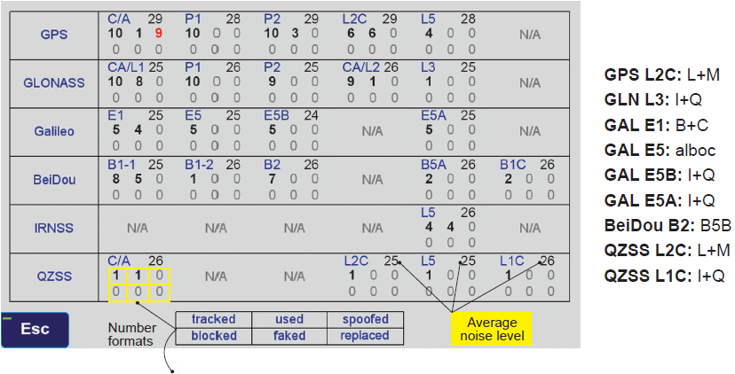
GNSS Overall View
The following screenshot shows the status of all GNSS signals. The format and the signal definitions are explained below.
Table: Javad GNSS
Tracked: Tracked by the tracking channels and has one valid peak only.
Used: Used in position calculation.
Spoofed: Has two peaks. Good peak is isolated, if existed.
Blocked: Blocked by buildings or by jamming. If jammed, shows higher noise level.
Faked: Satellite should not be visible, or such PRN does not exist.
Replaced: Real signal is jammed and a spoofed signal put on top of it. Because of jammer, it shows higher noise level.
7-channel multi-GNSS multi-band for software-defined receiver
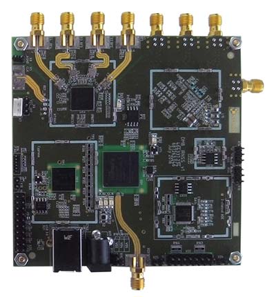
The NT1065/66_USB3 multi-channel GNSS RF front-end board is based on NTLab’s RF ICs: NT1065 (four channels for GPS / GLONASS / Galileo / BeiDou / IRNSS / QZSS, L1/L2/L3/L5 bands) and new NT1066 (two channels for all previously mentioned GNSS signals, plus one extra-channel for IRNSS S-band). The board supports USB3 connection, allowing users to process captured satellite signals on a PC or DSP platform. The board is accompanied by comprehensive software and manuals. Features include six channels for L1/L2/L3/L5-band signals + one channel for S-band signals simultaneous reception; up to four coherent channels; IF bandwidth up to 32 MHz; acquisition of wideband signals up to 64 MHz (such as Galileo E5) by two coherent channels; USB3 interface (up to 800 Mbit/s); ability to connect four x CRPA. NTLab offers an academic discount program for universities, colleges and institutes, allowing them to purchase this powerful research tool with significant savings.
Three new Tersus GNSS HRS kits feature high-precision BX305, BX306 and BX316 GNSS RTK boards. The kits consist of RTK receivers, GNSS antennas, RS05R radio station modems, radio station antennas, and related cables and converters. Embedded in the receivers are the Tersus RTK boards. They are compact-design, energy-efficient, centimeter-level accurate GNSS real-time kinematic (RTK) boards that bring high-precision positioning accuracy to the market. Different from the standard BX305/306/316 GNSS kits, the new HRS versions are equipped with the RS05R lightweight and robust UHF rover radio for wireless applications. It provides reliable data communication for demanding conditions that require a combination of stability, high performance and long-range operation. The kits can be used in a variety of applications, such as unmanned aerial vehicles (UAVs), surveying, mapping, precision agriculture, construction engineering and deformation monitoring.
Spoofer detection is now available on all JAVAD GNSS original equipment manufacturer (OEM) boards. When a receiver equipped with a JAVAD board detects more than one correlation peak for any PRN code, it warns the user of the presence of spoofing (false signals) and identifies the spoofed satellites. The receivers then switch to other signals and sensors that are not being spoofed to maintain accurate positioning. The user can also employ the receiver to try to identify the direction from which the spoofing signals are originating.
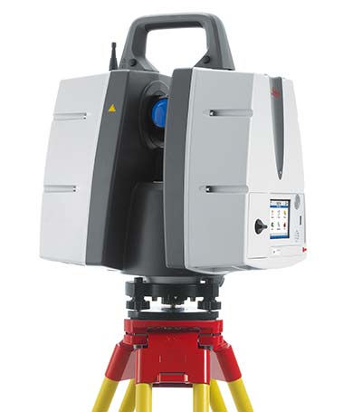
The ScanStation P50 combines all the features of the P40 plus a longer range scanning capability of more than 1 kilometer. The rugged, versatile laser scanner enables professionals to 3D capture at great distances with angular accuracy paired with low-range noise and survey-grade dual-axis compensation. The ScanStation P50 opens new business opportunities for reality-capture professionals, helping them to scan what was previously unreachable such as big mine pits, long bridges, dams and skyscrapers. With its range, the P50 enables users to scan any tall or wide infrastructure or dangerous sites from a remote and safe position. This newest member of the P-Series provides the highest quality 3D data and high-dynamic range (HDR) imaging at an extremely fast scan rate of up to 1 million points per second and ranges of more than 1 kilometer.
Azuga FleetMobile: Standalone Smartphone Edition (SSE) is a smartphone-based solution for driver behavior monitoring, mobile timecard management and GPS tracking. Azuga FleetMobile SSE leverages data analysis components of the original Azuga FleetMobile application, including driver behavior monitoring, location-based timestamps for timecards, gamification and driver rewards, without requiring separate hardware installation via a vehicle’s OBD port. Azuga’s GPS fleet-tracking offerings feature a driver rewards program to help fleets reduce accidents by up to 70 percent. The standalone application, which works on both Android and iOS smartphones, integrates gamification and real-time data to encourage self-coaching and healthy competition. Azuga’s data science team can then leverage information about driving behaviors and combine them with route patterns, fleets’ vehicle health information and environmental factors to identify opportunities for performance improvements in fleet operations.
The RIFA series of full-featured GPS trackers have built-in gyro and G-sensors, and supports OBDII and J1939 protocols. In addition to 4G/3G communication, it provides options to use low-power wide-area networks (LPWAN) such as NB-IOT or LoRa, which can reduce communication costs significantly. The unique CAN-to-ADR (automotive dead reckoning) function provides accurate positioning in situations of weak GPS signals, such as driving in tunnels, indoor parking facilities, urban canyons or when GPS signal obstruction hinders positioning, without additional cabling for wheel speed input.
The ThermalCapture IRnet provides an Ethernet interface for live data streaming to new and existing FLIR Tau 2 drone cores and FLIR Vue Pro/R cores. The market has increased its demand for connectivity by Ethernet, with professional drone manufacturers choosing Ethernet for communication on board UAVs. The ThermalCapture IRnet allows for real-time access via Ethernet while recording radiometric data to microSD, bringing real-time access in drone flight operations to thermal imaging data. It stores the full 14-bit radiometric thermal data on a microSD card. Real-time access remains available while radiometric data are being recorded; operators can also control the camera and settings via Ethernet. Using Ethernet also offers data privacy.
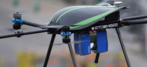
The Think 3D Stormbee multicopter integrated with Trimble’s AP15 provides efficiency, accuracy and performance for lidar surveys from unmanned vehicles. The Stormbee is a directly georeferenced UAV lidar solution for 3D industrial mapping applications, designed to collect survey-grade spatial data more cost effectively and efficiently than static lidar. Stormbee’s 3D mapping technologies include Faro’s Focus 130 laser scanner, Trimble’s AP15 high-performance GNSS/inertial receiver, Applanix’s POSPac UAV GNSS/inertial post-processing software and Stormbee Beeflex software for lidar point-cloud generation. By using the high-performance Trimble AP15 with two antennas and the Applanix post-processing software (POSPac MMS) for georeferencing the lidar data, Stormbee provides an accurate real-time and post-mission solution for all motion variables.
Spoofing — the generation of false and misleading GPS signals by “bad actors” — is becoming an increasing problem for all GPS users, and surveyors just as much as everyone else should be knowledgable and take countermeasures.
Javad GNSS has announced that spoofer detection is now available on all of its OEM boards. If the receivers equipped with such boards detect more than one correlation peak for any PRN code, they warn the user of the presence of spoofing (false signals) and identify the spoofed satellites.
The receivers then switch to other signals and sensors that are not being spoofed, to maintain accurate positioning. The user can also employ the receiver to try to identify the direction from which the spoofing signals are originating.
Virtually all defense and security applications of GPS/GNSS require additional technology to protect assets and missions against signal interference, whether jamming or spoofing. The upcoming free webinar, Resilient PNT for Military Applications, gives a primer on several of these technology options. Mitigation in this context means that after isolating the unwanted signal, quickly rejecting and replacing it, causing minimal system degradation. In essence, this involves the use of augmentation technologies and diversification strategies to supplement GPS/GNSS, thus reducing the dependence on it.
Applications relevant to this approach include: Airborne: Observation payload (radar, optronics, electronic warfare), flying test bench, flight analysis, tactical UAV navigation;
Ground: Blue Force tracking, vehicle navigation, satcom on the move (SOTM), Anti IED jamming systems, mobile radios and C4ISR, robotics;
Marine/Naval: Sensor support (radars, sonars, optronics, electronic warfare), communication networks, offshore/DSO platform.
Possible sources of such additional technology include those shown in the accompanying figure:
Click to enlarge.
The webinar is targeted upon the needs of systems engineers, system integrators, communication engineers, information system security engineers, validation engineers, test engineers, defense engineers, contractors and consultants, application engineers, systems and requirements analysts and system administrators who wish to firm up their understanding of resilient PNT and expand upon the alternatives available to them. Speakers on the webinar will cover the topic from a range of perspectives.
Mike Jones has worked on a variety of UK and US military airborne platforms around the world. He specializes in the simulation, modeling and hardware implementation of advanced signal processing algorithms, and has led a number of FPGA and ASIC designs for radar, GPS and communications systems.
Mikel Miller began his career as a satellite systems engineer with the U.S. Air Force, holding numerous test, research and development, and program management positions. He retired with a Ph.D. and rank of lieutenant colonel. He worked until recently as chief scientist for PNT Technologies for the Air Force Research Lab Sensors Directorate, and is now a vice president at Integrated Solutions for Systems (IS4S).
Miller will broaden the discussion to encompass all three technologies that evolved military applications and platforms now require for synchronized, precision operations: resilient PNT, resilient communications, and resilient cyber. A system-of-systems architecture that integrates and optimizes these three technologies is required to provide trusted and resilient PNT information in GNSS denied/degraded environments.
Randy Villahermosa, executive director, iLAB, The Aerospace Corporation, will speak on research concepts in complementary PNT, including open-source frameworks and the potential role of signals-of-opportunity navigation. The iLab is a venue for “exploring, prototyping, and collaborating.”
Lisa Perdue, an expert in testing critical GPS and GNSS systems, has trained hundreds of engineers and technicians who are responsible for high-reliability positioning, navigation and timing (PNT) applications. Perdue is Spectracom product manager at Orolia, where she directs the organization’s GNSS simulation activities and contributes to its entire portfolio of resilient PNT solutions. She has more than 15 years of navigation and RF systems experience, including 10 years of service with the U.S. Navy, where she was a certified master training specialist.
Spectracom’s perspective on secure military systems is concisely set out in a whitepaper, “Making Military PNT Systems Resilient Against Threats: Recent Advances.” After an overview of the field in which many terms and concepts are carefully and helpfully defined, the whitepaper explains the advantages of the new Satellite Time and Location (STL) service. This is a paid option available on the company’s VersaPNT hardware unit, combining a GNSS receiver, inertial measurement technology and high-performance timing oscillators to provide assured PNT in GNSS-degraded and denied environments.
STL is a new technology available today to harden GNSS-based timing and frequency systems, and in some cases even to replace the GNSS reference; the adaptation of this technology to positioning and navigation applications on slow-moving mobile platforms is currently under development. The STL signal is broadcast by the Iridium constellation of satellites in low-Earth orbit.
VersaPNT reduces size, weight and power (SWaP) by combining the the PNT functions of multiple independent subsystems in one portable unit with a modular architecture. For improved resiliency, optional interference detection and mitigation (IDM) software can be added, as well as other services such as STL and BroadShield.
“Prepare for Tomorrow: Find Vulnerabilities Today” was the title of our wide-ranging webinar in July that focused on GNSS signal simulation for jamming and spoofing scenarios. We did not have time to address all the questions posed by the audience, so we return to them here.
Q: While testing receivers, realistic scenarios for jamming and spoofing are very important. What is the typical approach to set the number of interference sources, their type and main signal parameters?
Two different approaches are common, those involving the use of an anechoic chamber and those which are lab-based. Each approach has its limitations and merits. Each approach must address the number of significant interferers, their signal powers and the waveforms of the interference signals. Each must also consider the geometric arrangement of these interferers relative to the antenna under test and relative to the simulated constellations under test.
Changes in signal phase, signal Doppler and signal power are as important for the interference signals as they for the wanted GNSS signals. These changes are caused by the simulated motion of the vehicle and potentially the motion of the interferers. These changes should also include the impact of terrain surrounding the vehicle and the interferers, and also the gain and phase patterns of the receive antenna on the vehicle and the transmit antennas on the interferers. Some interferers might be discounted from the significant set due to their signals being masked from the vehicle by the terrain or antenna patterns or by them being too far from the vehicle to have an impact. These interference signals may become significant as the scenario progresses due to vehicle or interferer motion.
Simulator graphical user interface. (Image: Spirent Federal Systems)
Q: In GNSS navigation systems for commercial applications, what emphasis of design effort should be on anti-jamming/anti-spoofing over improving the navigation accuracy?
Commercial applications is a broad area, so it will depend on the particular application as to whether it needs more accuracy or more resiliency against AJ/AS, but in general, the accuracy of GNSS is fairly mature. Standard GNSS offers accuracies on the order of ~1 meter. Centimeter accuracy can be achieved with differential or real-time kinematic (RTK). Multi-constellation use can increase availability in areas with limited sky view such as urban canyons. Multi-frequency can aid in the reduction of multipath and improve accuracy. If the application needs accuracy, these features are readily available.
However, integrity and resiliency are growing needs in commercial applications, especially ones that are in critical operations. Much more can be done to detect jamming and spoofing than what is in standards GNSS receivers today. In our systems, we include an additional software layer called BroadShield, which monitors internal state variables of the receiver, and will alarm on detection. Additional sensors combined with the GNSS receiver such as an inertial measurement unit (IMU), magnetometer, odometer, or even the much stronger Satellite Time and Location (STL) signal offer augmentation during periods of GNSS denial, or in the case of spoofing, authentication of the navigation solution.
While both jamming and spoofing are intentional attacks, they are highly different in their set-up and serve very different purposes. Due to their simplicity, most jamming attacks can be mitigated thanks to adaptive filtering or pulse blanking. On the other hand, spoofing is a malicious attack, highly complicated, and requires knowledge of the GNSS signal structure as well as precise timing and positioning.
The question is thus whether one should emphasize navigation accuracy over the ability to output a position (jamming case) or the possibility to output a completely erroneous position (spoofing case). The answer lies, obviously, in the end application and the coupling of GNSS receivers with other systems. High-precision non-life-critical applications should emphasize navigation accuracy while implementing simple jammer filtering strategies. Life-critical applications, being often coupled with other systems, should ensure the reliability of the solution even if that means being unable to compute a position due potential threats.
Q: Do you have GPS/inertial navigation system (INS) test capabilities?
The CAST-3000 EGI integration system produces GPS RF signals commensurate with simulated IMU sensor data to provide repeatable testing in the integration laboratory for a wide range of military and government applications.
CAST GNSS/INS simulators generate high-fidelity signals required for emulating the legacy GPS signals as well as those used by next-generation navigation technologies. This is because our sole business focus is supplying GNSS simulators, GNSS/INS test equipment, and GNSS/INS support services to government and military avionics laboratories, prime contractors, and GNSS receiver manufacturers. For 35 years we have provided off-the-shelf products to both the government and U.S. major defense contractors.
CAST EGI integration tools are used by Northrop Grumman and Honeywell and are now also being used in integration laboratories worldwide. Our equipment supports system integration in major weapons platform labs and development at major military contractor labs. CAST simulators produce high-quality, accurate signals that are used in government, military and commercial labs around the globe.
Our NCS TITAN GNSS simulator is able to emulate the presence of IMUs and micro electro-mechanical systems (MEMS) sensors with the optional available real-time IMU/Sensor Emulation Package (SEP). The SEP upgrades the TITAN to support the simulation of inertial sensors, which nowadays are implemented as MEMS, among others, and of other common aiding sensors. To obtain more accurate positioning for location-based services and navigation, GNSS chipset and receiver manufacturers as well as system integrators combine more and more GNSS navigation with such sensor fusion or signals of opportunity.
The optional SEP enables controlled and progressive testing of sensor-fusion algorithms when used with NCS Control Center operating software. This software supplies the SEP with an internally- or externally-generated center-of-gravity (CoG) trajectory for the device under test.
The various sensor models to be emulated by the SEP run within the Control Center software. The device under test (vehicle) input trajectory at the CoG passes through the sensor model, which in turn generates the appropriate sensor output, by taking into account the corresponding error model for each sensor defined.
We have added the capability to emulate INS/IMU data in addition to GNSS signals to our Constellator simulator, to offer to the customers a complete testing platform. Constellator can simulate up to six gyrometers and six accelerometers. The attitude of each sensor is defined with respect to the vehicle axes. Deterministic errors can be configured to simulate the axis misalignment and scale factors, and biases can be defined in order to simulate realistic sensors. Stochastic error models are also available such as random walk or Gauss-Markov models for each sensor (gyrometer or accelerometer) to improve the sensor emulation fidelity.
Q: Do you have detailed scenarios for jamming and spoofing in timing use of GNSS receivers, that is, involving time synchronization for telecommunications companies?
The simulated jammer’s signal specification must be very flexible in order to faithfully simulate real-world jamming events. For example, the jammer’s spectral shape should be flexible enough to simulate a Blue Force electronic attack (BFEA) on a GNSS receiver.
Also, the simulator should be able to simulate dynamic scenarios by varying the power of the jammers as a function of their trajectories and as a function of different antenna patterns.
Sometimes when testing receivers, the simulated jammers should replicate pre-recorded waveforms from real world. The ability to play back the pre-recorded IQ-baseband signal in conjunction with GNSS signals is another powerful feature of a simulator. Simulation of spoofing attacks on a GNSS timing receiver is only possible when the GNSS simulator provides fine-grained control of transmitted signal. This includes controlling the offsets on the pseudoranges with additive ramps, as well as individual signal power levels at very precise points in time.
Also, the GNSS simulator must be able to synchronize itself with the live sky’s GNSS signal. Another way to achieve realistic spoofing is to use two simulators controlled independently (that is, full control on constellation, navigation message, propagation time offset, power and so on).
FIGURE 1. Real-world jamming simulation must take into account key factors such as varying jammer power, as a function of their trajectories and antenna patterns. (Image: Skydel)
Q: Please discuss how to simulate a smart spoofer that would generate a replica of a constellation (or all constellations) and then produces two full RF transissions: one that is the true signal, and a strong spoofed signal that pulls the receiver to a false location. Can you simulate the two full multi-band RF ensemble?
Two artificial synchronized scenarios could be created using SatGen signal generator software that can reproduce the GNSS signals from a number of constellations. The user could create two separate signal streams, both starting at exactly the same position and time and using the same constellations, chosen by the user.
The second scenario could then be set to diverge away in position from the first scenario, while staying perfectly synchronized in time. The signal-to-noise ratio of each scenario could be adjusted independently of each other to simulate a spoofing situation where the spoofing signal is much stronger than the real signal. A file containing this twin scenario can be replayed using a LabSat Wideband with two separate RF outputs, each synchronously replaying the two different scenarios. This would closely simulate the actions of a smart spoofer, but in a completely repeatable, and controllable manner.
This could be accomplished by either combining the output of two of our CLAW GPS simulators, or by combining the output of a single CLAW simulator with live-sky signals using passive industry-standard splitters/combiners. The CLAW is able to receive a custom ephemeris download in RINEX format to match either the spoofed live-sky constellation, or to generate a synthesized constellation in the case where two CLAW simulators are being used.
The simulator has a wide RF power adjustment range of over 45-dB, allowing the spoofing signal to be gradually introduced to the primary GPS constellation RF signal. This spoofing simulation could be accomplished with better than 0.5 meter peak-to-peak positioning accuracy and better than 5-ns real-mean-squared (rms) typical UTC (GPS) offset unit-to-unit, allowing the victim receiver to be pulled off of its true (live-sky) position with very high accuracy. Typically, GPS receivers are spoofed easily as long as the UTC timing synchronization is 500-ns or better between the live-sky and spoofed signals.
Timing synchronization to the spoofed victim GPS signal to within nanoseconds is achievable through the external 1PPS reference input, the simulator accepting a position, navigation and timing (PNT) fix in real time via its NMEA serial and 1PPS inputs. This allows capturing a moving victim receiver by estimating its momentary position, then ramping up the spoofer power, and then presenting the victim receiver with alternate position information as required (see Figures 2 and 3).
High position and timing accuracy between the spoofed and live-sky signal is important to prevent and mitigate spoofing detection via UTC phase or position jumps that could happen when the receiver gradually or quickly switches over to the spoofed satellite signals.
FIGURE 2. Spoofing attack on a GPS receiver using a CLAW simulator to spoof a live-sky antenna signal. Initially the spoofer was phase- and frequency-synchronized to UTC(GPS), then spoofer RF power is ramped up, and once the victim GPS receiver is captured, a frequency offset is added to UTC(Spoofer), which pulls the system off-phase. (Figure: Jackson Labs)FIGURE 3. Simulating a spoofing attack on a timing application where the spoofer does not know the exact victim antenna location with certainty. The resulting antenna position offset error (50 meters in this simulation) still allows the victim receiver to be captured, and then causes a time error as satellites move in and out of view even with the spoofer being synchronized to UTC(GPS) at all times. This error is clearly visible in the resulting UTC(Spoofer) output from the victim receiver equipment. (Figure: Jackson Labs)
Q: We want to correctly model and simulate effectiveness of various anti-jamming (AJ) and anti-spoofing (AS) solutions to make informed decisions about which AJ/AS solution is most effective for a specific mission and interference scenario. How can you help?
Live-sky testing on a jamming/spoofing range provides a wealth of data, and reassurance that the system under test does work as intended. Record and playback systems (RPS) under live-sky conditions can allow further evaluation back in the lab, after the live-sky tests are complete. Performance parameters of the RPS may degrade the validity of the signal when played back; signal bandwidth and bit-depth are absolutely key, for example. Recordings that use too few bits will degrade the dynamic range of the recorded signals, so significant care should be taken when selecting an RPS.
Either way, under live-sky or with recorded live-sky, you get what you get. It is extremely difficult to predict what the test parameters actually are. It is perilous to attempt to alter the test parameters after the event. Lab-based or anechoic chamber-based systems have their limitations, but they are repeatable, predictable and tweakable. Again, performance parameters of the simulation system play a key role in the validity of the testing. The ability to calibrate the simulation system to give a repeatable, predictable performance is as important as the realism of the simulation. Carrier-phase accuracy/repeatability among antenna elements and signal timing accuracy are important parameters when evaluating AJ and AS systems.
Q: We had a receiver where the time stamp for any location report would drift off progressively, up to an hour off of the known true location. What might contribute to this? We do not believe this was an intentional threat, but an artifact of nearby electronics or other system conditions. It actually occurred on a pivot irrigation arm in motion, with substantial vibration. The receiver was electrically isolated. The results were repeatable on the pivot arm, but not on our vibration table.
Interesting problem with no obvious answer. Even the worst oscillator will take many months to drift off by up to an hour with no GNSS, even under horrible vibration conditions, so this is an unlikely cause. Is it drift or a jump in error? Nearby electrical noise could cause GNSS denial (jamming), but not erroneous data. That requires spoofing. If you have no reason to believe that it is intentional, that makes spoofing unlikely, but still possible. Is a GNSS repeater or a record/playback GNSS tester operating in the area? These are spoofers, even if they are unintentional.
If this is a precision agriculture application, then an RTK reference station transmitting erroneous data could be the cause. What time-stamping format is used: local time or UTC? An unlikely but possible scenario is the unit is changing time zones so local time jumps an hour. Is there a processor/software app between your output and the actual GNSS receiver? This could introduce errors. What is the position output indicated when the time drift occurs? The best way to diagnose this is to record the time and position output as log files using a laptop PC connected to the serial data.
Q: Do your simulators work as well for testing handheld, consumer-grade GPS? Please discuss the differences in testing techniques or approaches for high-precision vs. mass-market receivers?
We have a range of simulators suitable for all levels of GNSS testing. If you don’t need the high fidelity and wide bandwidth of the LabSat Wideband, then the entry level LabSat 3 will also work with any GNSS device including handheld consumer-grade products.
To fully explore the performance of high-precision receivers, including multipath effects and P-code reception, a wider bandwidth and a greater number of bits would be required to capture and replay all of the available signals. For these applications, we recommend a bandwidth of 56 MHz and at least 4 bits of resolution.
For testing of consumer-grade, handheld devices with simpler RF front ends, we recommend a much reduced bandwidth of around 9 MHz and only 2 bits of resolution. This smaller bandwidth and fidelity will easily reproduce the majority of real-world conditions, and the resulting data files will be much easier to handle.
FIGURE 4. Simulator graphical user interface. (Image: Racelogic)
Q: How many GNSS signals can a software-defined radio produce?
The theoretical limits of a software-defined radio (SDR) are based on four distinct characteristics of the SDR: the digital-to-analog converter’s (DAC’s) bit resolution, the maximum sampling rate, the bandwidth and the number of RF outputs. With most SDRs, available bandwidth is defined by the sampling rate.
With a 16-bit DAC, there is enough dynamic range to generate up to 50 GNSS signals and hundreds of multipath echos (with more than 60 dB of range to accommodate different signal power levels) per RF output.
For example, with a sampling rate of 50 MSps, a 40-MHz wide signal — combining GNSS constellation signals such as GPS L1 C/A, Galileo E1, GLONASS G1 — can be generated. Nowadays, SDRs can have two or more RF outputs and are able to operate with sample rates of 100 MSps or higher. By distributing the GNSS signals across different RF outputs, the entire GNSS spectrum can be covered at a relatively low cost in terms of hardware.
A handful of SDRs can easily be synchronized to form multiple RF output systems. In such cases, the complete range of GNSS signals for all visible satellites can be generated at the same time.
Q: In a dual-frequency receiver would it be possible to still use L1 spoofed/jammed with L2 clean to get an accurate position? Is it possible to do a combination between the two signals in order to save the spoofed/jammed L1?
In principal, it is still possible to use L1 spoofed/jammed with L2 clean in a dual-frequency receiver to get an accurate position. Such receivers are available as off-the-shelf products. These receivers use a special algorithm to detect if a GNSS frequency band is spoofed/jammed and automatically switch over to the clean frequency band. However, this principle can only be applied if the entire GNSS spectrum is not completely jammed. Whether a dual-frequency receiver can still use L1 spoofed/jammed with L2 clean to get an accurate position is therefore finally basically dependent on the overall bandwidth of the interferer/jammer.
With IFEN’s TITAN simulator, it is possible to easily create the corresponding simulation scenarios for the real-time simulation of realistic test scenarios to test the robustness of GNSS receivers against interference/jamming and also spoofing. In doing so, various static and dynamic interference/jamming sources are supported by the simulator’s software.
It is possible to achieve a PNT solution using L2 signals only. This requires reception and decoding of either the military L2 P(Y) signal, or reception of the new but still pre-operational L2C commercial signal. Codeless or semi-codeless commercial L1/L2 receivers rely on tracking the carrier phase on L2 to be able to mitigate effects such as solar flares and ionospheric errors; however, they are not capable of generating a PNT solution with L2-only reception as would be the case under this spoofing/jamming scenario.
P(Y) signal reception on L2 typically requires reception of the coarse acquisition (C/A) signal on L1 prior to tracking P(Y) unless the receiver has its own internal (atomic) time-base synchronized to UTC to the sub-microsecond level.
On-Demand Webinars
Simulation against Jamming and Spoofing: With cyber attacks on the rise, it is more critical now than ever to thoroughly test GPS and GNSS systems against jamming and spoofing.
Spurious signals in the Black Sea have repeatedly placed seagoing vessels, according to their navigation systems, on the site of an airport hundreds of miles from their true positions.
The incidents were reported in the August and October issues of this magazine, and in Mike Jones’ Defense PNT e-newsletter column for October. Experts initially concluded the problems probably indicated a spoofing attack in the area.
Satellite image of the Black Sea.
A reader of the Defense PNT e-newsletter commented, “We have been following this case for quite some time now. We track all merchant vessels worldwide on the basis of Automatic Identification System (AIS), 24/7. The AIS transponder uses the GPS receiver for its position report.”
Our correspondent is the director of a company that offers server- and web-based tools that can be incorporated in GIS and asset tracking and tracing systems.
“The ‘spoofing’ is still going on,” he continued. “Even today ships were placed on the airport runway. In total, over 600 vessels were placed on the runway since early June. Our preliminary conclusion is that the ‘spoofing’ is probably not done on purpose. The most likely cause of this spoofing is a GPS re-radiator transmitter located in the hanger close to the end of the runway. This device is used for testing GPS when planes are placed inside the hanger. So, line-of-sight interference?”
The comment drew the immediate interest of security consultants who continue their investigations.
Baltic Incidents. Meanwhile, the Washington Post reported that a disruption of Latvia’s cellular network and emergency-services hotline may have resulted from a test of Russia’s electronic-warfare capabilities.
A 16-hour outage in October occurred at the time of major Russian military exercises. If substantiated, this could reveal electronic-warfare assets with capacity to disrupt civilian communications remotely. Such a tool could severely hamper authorities’ ability to organize a quick civilian response in case of war.
“Because of maneuver warfare’s reliance on communication, Russia has invested heavily in electronic warfare systems which are capable of shutting down communications and signals across a broad spectrum,” stated a December 2016 publication by the U.S. Army’s Asymmetric Warfare Group. “The Russians layer these systems to shut down FM, SATCOM [satellite communication], cellular, GPS and other signals.”