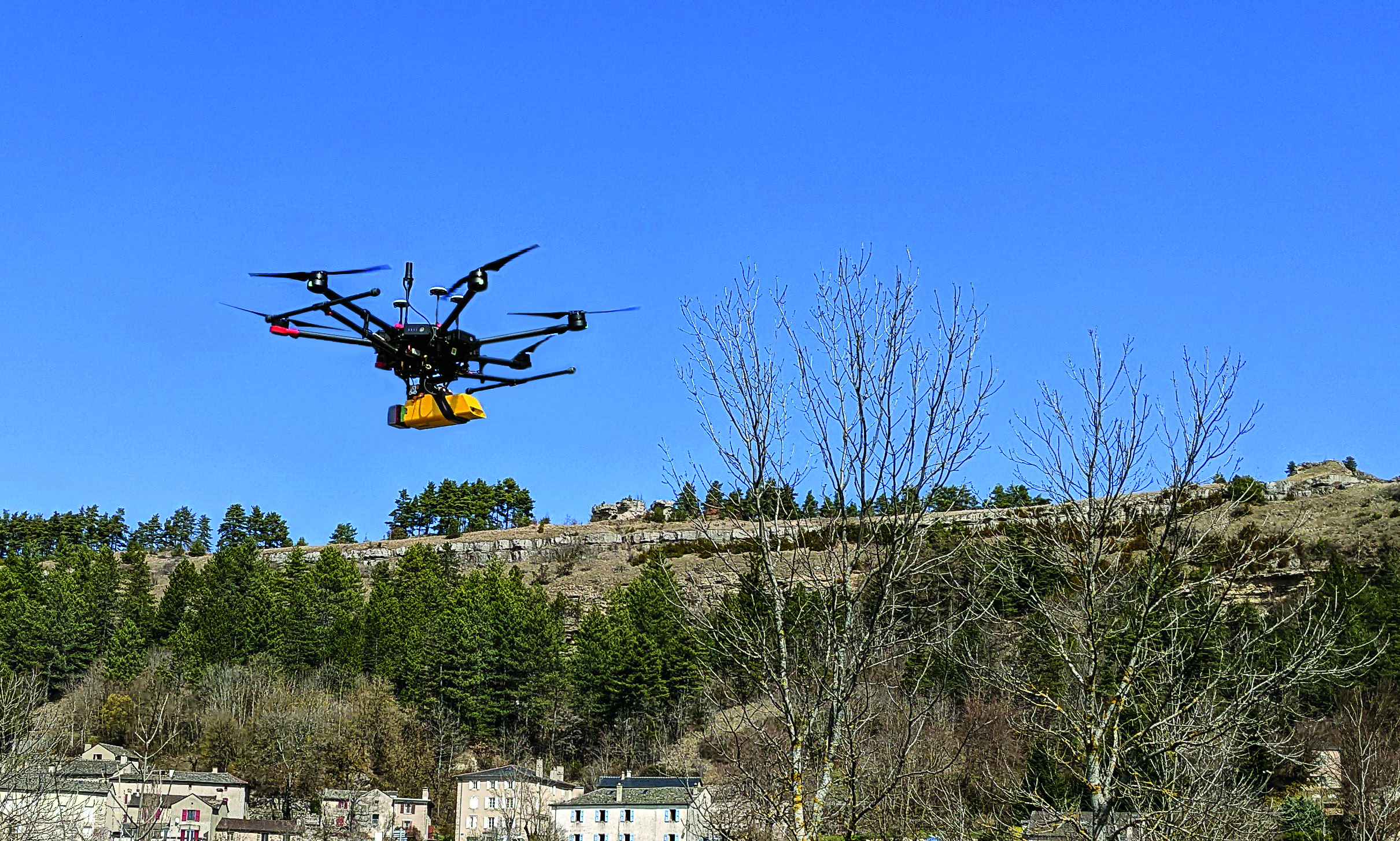
L’avion jaune, a French UAV and aerial photogrammetry company, uses the Trimble Applanix APX-20 UAV GNSS-inertial OEM solution and a YellowScan VX-20 lidar on its M600 multirotor UAV. (Image: L’Avion Jaune)
The breakdown of limestone cliffs generates landslides and loose debris that threatens the environment, people and wildlife below. These conditions make it impossible to safely operate traditional survey equipment from the ground for landslide detection. Using UAVs for direct georeferencing is an efficient way to take traditional survey efforts to the sky and enables users to accurately assess land formations while mitigating risk.
One way to implement direct georeferencing on UAV platforms is with the Trimble APX-20 UAV, which is a GNSS-inertial OEM solution that increases the mapping efficiency of small UAVs. It consists of small, low power, precision GNSS and inertial hardware components and POSPac UAV post-mission differential GNSS-inertial office software. The APX-20 UAV eliminates the need for ground control points and reduces the sidelap required to be flown per flight.
The APX-20 UAV contains a precision, survey-grade GNSS receiver and dual inertial measurement units (IMU), so it automatically supports integration on gimballed platforms without requiring an external interface to an autopilot or on a mount. It computes at 100 hz using the embedded IMU while simultaneously logging the raw IMU data from both the internal and external IMU at 200 hz for post-processing in POSPac UAV. The postprocessed position and orientation solutions are suitable for direct georeferencing of cameras, lidars and other sensors.
Trimble Applanix UAV Put to the Test
For fast and safe landslide detection, the Trimble Applanix APX-20 UAV for direct georeferencing was put to the test using a Multirotor M600 manufactured by French company L’Avion Jaune equipped with a VX-20 lidar sensor made by YellowScan, also a French company. This combination produces cost-effective and reliable high-resolution UAV lidar-derived DTMs and 3D models for hazard mitigation and planning.
L’Avion Jaune has performed more than 600 successful mapping missions globally. After pursuing mapping activities with mainly crewed aircraft, it began developing UAVs for long-distance applications for marine, tropical forest and polar regions such as the Multirotor M600/YellowScan VX-20, which offers high-precision, cost-effective and efficient aerial mapping.
The APX-20 UAV and the M600/YellowScan VX-20 were combined and deployed to evaluate landslide activities in France. The mission parameters for this configuration included: high point density; x, y, z precision of 5 cm; access to dangerous zones; map generation under dense vegetation area, and fast deployment. The goal of this project was to enable the implementation of safety and prevention plans for the protection of pedestrians, infrastructure, wildlife and more.
During the six-hour duration of the project, the APX-20 UAV and M600/YellowScan VX-20 configuration was flown four times for 15 minutes each during sunrise. It flew more than 75 ha in surface area with a flight speed of 5 m/s at 60 m in the air, following the topography. Checkpoints were surveyed with differential GPS following the conclusion of the flights. Data processing included computation of the georeferenced trajectory, matching flight lines and point cloud classification, which took two days.
The Results
The flexible UAV deployment of resources enabled the acquisition of dense point clouds and the generation of DTM in less than three days. During this project L’Avion Jaune was able to optimize the choice of material and discover the best practices to collect and process lidar data for mapping in dense vegetation.
NV5 Geospatial has forged a contract with the Caribbean Community Climate Change Center (CCCCC) to conduct aerial lidar and orthoimagery surveys across the Caribbean. The pilot project will provide advanced geospatial data to help the island nations understand natural and man-induced climate changes, develop programs to support resilience and sustainable development, and establish a foundation for future work.
NV5 Geospatial will conduct topographic and topobathymetric lidar surveys, as well as orthoimagery, via a fixed-wing aircraft. Data collected will help CCCCC address the impact of climate variability and identify potentially hazardous impacts.
The project will cover 10 sites spread across more than 3,000 km. The sites include areas in Suriname, Guyana, Tobago, Barbados, St. Vincent and the Grenadines, Saint Lucia, Antigua and Barbuda, St. Kitts and Nevis, Turks & Caicos and Belize.
Other logistical considerations include the combination of microclimates inherent around tropical islands, highly variable weather conditions, cloud formations and jungles, some of which are in high relief areas or covering the entire area.
Mason and Dixon were pioneers in bringing geodetic astronomy to the American colonies. Through the efforts of the Mason and Dixon Line Preservation Partnership, we can promote this scientific contribution along with the placement of the boundary stones.
Ask surveyors why they became engaged in the profession and why they had continued with it, most will centralize on one aspect: working outside. A career that allowed them to work outside in various environments, solving problems, and being part of a solution is typically the main answer they give.
Depending on the task at hand, a day in the field surveying can take one to several places, including urban/suburban neighborhoods, construction sites, and agricultural/wooded farmland.
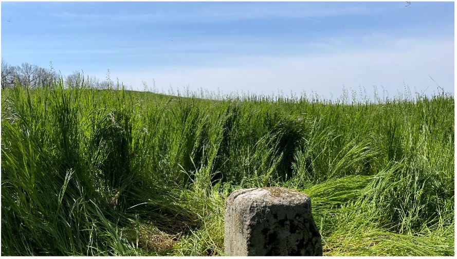
View from Mason Dixon Stone #95 looking toward Maryland. (Image: Tim Burch)
My entry into surveying was no different. From residential sites, condominium surveys, boundary and topographic surveys, and construction layout, my early years in surveying covered a lot of territory. While my career eventually took me out of the field and into an office managerial role, and now into leading a professional association, it does not erase the roots of one’s surveying knowledge and experience. Opportunities to be part of the field exercises of a survey, especially a boundary survey, are typically rare and subject to time constraints.
Having spent all my life in the flat topography of Illinois and surrounded by farm fields and urban sprawl, the ability to see for miles over the various horizons was the norm. Coupling these conditions with the Public Land Survey System (PLSS) and use of GNSS technology, it makes for a great environment for the professional surveyor to go about his or her work.
However, the United States covers many areas and contains distinct types of terrain, ecosystems and demographic groups that provide challenges to the surveyor. While I assumed moving from Illinois to the mid-Atlantic region would require adaptation, an opportunity to help retrace and inventory a significant part of American history provided me with an eye-opening experience. It also helped me appreciate the legacy of our surveying forefathers.
A small title dispute
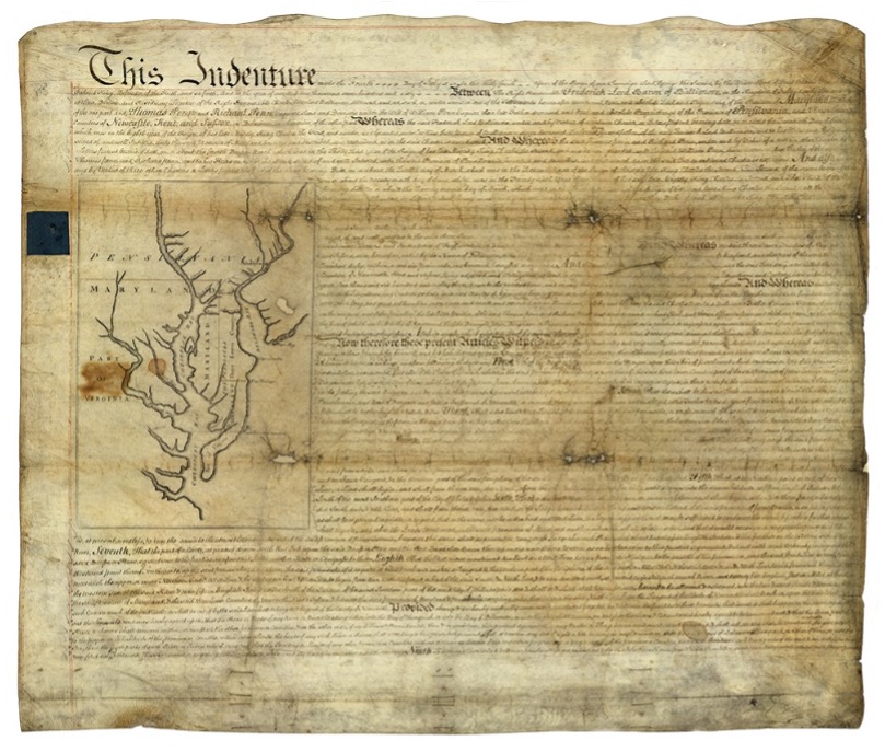
Even in the 17th and 18th centuries, disagreeing title descriptions to common lands was an issue. Reviewing two conflicting legal descriptions describing adjacent land boundaries is the basis of this survey exercise, and thus began a symbolic establishment of a famous boundary line that would lead to political and demographic ramifications in later years.
Here is the situation:
1632: King Charles I grants to Cecilius Calvert (second Lord Baltimore), a royal charter for establishing a new colony north of Virginia to a point “which lieth under the Fortieth degree of north latitude” and westward to the source of the Potomac.
1681: King Charles II (eldest son of Charles I) grants William Penn a royal charter of land between 43° N and a line extending westward from “a Circle drawn at twelve miles distance from New Castle…” to “the beginning of the fortieth degree….”
1682: King Charles II grants to William Penn an additional grant in the Delaware peninsula, which Lord Baltimore claimed.
1685: King Charles II directed his Board of Trade and Plantations to issue an edict ordering that territory to be divide equally, the western half going to Baltimore. This order endorsed Calvert’s claim of a boundary line being 19 miles to the north and providing him claim to Philadelphia. Part of the edict placed a burden on Calvert of providing a survey to authenticate the claim, but the survey was not completed. The boundary would eventually be established 19 miles to the south.
1731-1732: Charles Calvert, the fifth Lord Baltimore, petitioned King George II for help in demarcating the final boundary. He agreed on the final boundaries; however, a commission created to study the legal claims failed to deliver instructions in which a survey would be based upon. Calvert disputed its interpretation and refused to implement the arrangements.
1730s: Ongoing conflict over the disputed land claimed by both people from Pennsylvania and Maryland resulted in Cresap’s War, named after the land agent, Thomas Cresap, hired by Calvert to settle new development. In 1736, Cresap was accused of murder, arrested by Pennsylvania officials and his housed burned was burned down.
1750: After years of bitter controversy, British Lord Chancellor Hardwicke ruled that the southern boundary of Pennsylvania should be a line running westward from the point at which the line dividing the Delaware peninsula was tangential to a circle with a radius of 12 miles from the center of Newcastle.
After 100+ years of boundary disputes and deadly confrontations, in 1760 Frederick Calvert was directed by the English monarch to accept the terms of the 1732 treaty.
Penn-Calvert Land Grant Agreement. (Image: National Archives)
The unfilled challenge, however, was to commission a survey to establish the terms of the agreed-upon boundary. Given that the final location of the Pennsylvania/Maryland border was geographically based (approximate latitude of N 39°43’20”), the surveyors chosen to establish this line would have to be knowledgeable in such calculations.
Finding qualified surveyors in the colonies turned into a bigger challenge than first considered, so the monarchy assigned two surveyors from the Royal Society (full name: Royal Society of London for Improving Natural Knowledge). Enter Jeremiah Dixon (surveyor) and Charles Mason (astronomer) — the field party charged with tackling this monumental deed.
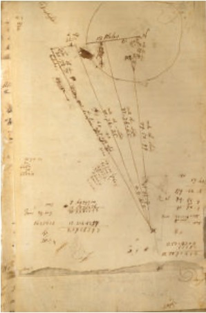
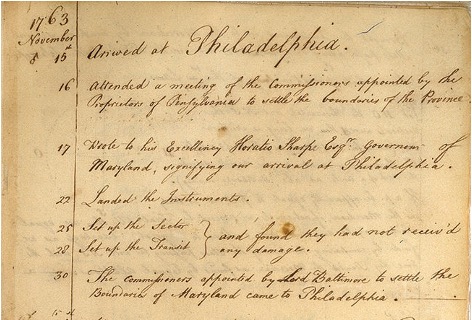
The survey calculations of Charles Mason. (Image: National Archives)
We know them by name for the lines they established in fulfilling the requirements of the boundary agreement, but how they accomplished their task remains a mystery to most. Previous exercises using geographical position determination was used in the sailing and shipping industries with lesser degrees of accuracy. This assignment would require higher levels of accuracy and precision, hence the reason for calling upon Dixon and Mason for the task.
By using geodetic astronomy, they were able to determine accurate (for the period) geographical positions of latitude. Geodetic astronomy is the art and science for determining, by astronomical observations, the positions of points on the earth and the azimuths of the geodetic lines connecting such points. It relies on spherical astronomy, using calculations and techniques developed by the Greeks in the second century A.D.
Besides the knowledge of performing the necessary calculations, the duo would also need to possess instruments to gather the accurate astronomical information. The survey of the agreed-upon line was to be established upon a constant line of latitude. The survey procedures would require turning angles (azimuths) from their meridian westwardly with accuracy not yet utilized in the New World.
Both instruments used for the project were built by John Bird, a well-respected instrument maker in London. The equipment consisted of a zenith sector, capable of measuring to two arc seconds. No field azimuth instrument of this accuracy existed in that era. They also brought a converted telescope/level set up for surveying purposes. This transit has no divided horizontal “plate,” only a tangent screw for slow azimuth motion.
In addition to the instruments and astronomical tables from Greenwich and Paris, the duo relied on a highly precise clock for marking time by the second, which was quite advanced for the period.
Dixon and Mason spent the better part of 1766-67 establishing the agreed-upon line using astronomy via the Bird instruments and taking copious notes documenting their calculations and survey conditions.
Field notes from Jeremiah Dixon. (Image: National Archives)
The markers set along the way —stone monuments chiseled back in England with demarcations — were quite accurately established despite the primitive nature of equipment and methodology for the survey. Mason and Dixon laid out the 233-mile long “West Line” in short segments, following the latitude arc of approximately N39°43’20” for 233 miles westward.
Old line versus new technology
In 2020, the Maryland Geological Survey (MGS) and the Pennsylvania Historical & Museum Commission (PHMC), members of the Mason and Dixon Line Preservation Partnership, began a new initiative to inventory these historic markers and submit them for inclusion into the National Registry. If accepted, the monuments will be part of a program established to help protect and preserve these physical boundary markers that define the boundary between the two states.
Part of the inventory has been the recovery and position confirmation by volunteer surveyors from the Maryland Society of Surveyors (MSS) and the Pennsylvania Society of Land Surveyors (PSLS). Using a geographic information system (GIS) app designed and implemented by the Maryland Geological Survey (MGS), volunteer retracers capture significant attributes about each monument.
While reestablishing the latitude/longitude of the recovered monuments with a smartphone or handheld GPS receiver is sufficient, several volunteers have used high-accuracy surveying equipment to determine a monument’s position.
Incredibly, the variation in the location of a given monument is well within reasonable tolerances from the originally intended installation. Also, because of GNSS technology, we now know more about continental drift. Because of this additional knowledge, 250+ years of tectonic plate movement should be considered when making these positional comparisons.
It should be noted that these monuments are a critical component of the boundary between states, and therefore must be considered senior to many other survey corners set after them. We cannot get lost in the sentimental aspect of recovering the monuments and not acknowledge the fact these points are the gospel when it comes to defining these state boundaries.
A Midwesterner in a ‘foreign’ land
My surveying career, as noted above, was solely in a state that is 200 years old, based upon the PLSS, and does not carry the history of the Mason-Dixon era of line establishment. So, when I was presented with the opportunity to join fellow surveying professionals from Maryland and Pennsylvania in recovering Mason-Dixon monuments for the inventory, I found it an easy event to join.
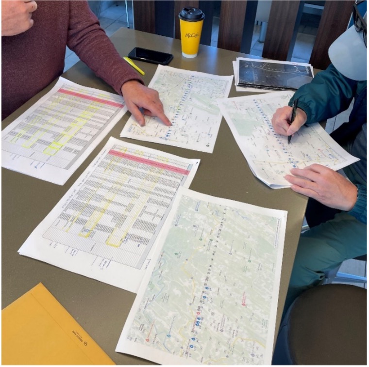
The planned meeting spot was a local fast food place at 8 a.m. on a sunny Saturday. Being it was in a small town, there were several groups meeting for their normal Saturday coffee klatches. Hearing a group mention “surveying,” I found my opening to identify myself as a fellow surveyor. After opening pleasantries, we settled into a game plan for recovering the targeted monuments for the day.
Planning a day of stone monument recovery along the Mason-Dixon line. (Photo: Tim Burch)
We settled on our assignments and enthusiastically went about our way. My partner for the day was Eric Gladhill, a Pennsylvania professional surveyor and veteran of Mason-Dixon monument retracement. In addition to his volunteer work, he has also authored several articles and a book on his surveying experiences, so it was quickly evident that we were in for a good day.
The first monument was not difficult to get to, and seeing it nearly brought a tear to my eye. Here before me was my first sighting of a Mason-Dixon monument stone, and it was simply amazing. Standing there admiring this 250+ year old stone, hand cut and carved in England and brought here by ship to be specifically placed on this line, I could not help but realize the importance of this monument.
This line, and these stones, were the culmination of two land grants that disagreed with each other more than 400 years ago. We were standing in the same location as a large survey party once did, where they observed the stars to determine an accurate position and directed axmen to clear the untamed forest to establish this important line. While it was a warm and sunny day, it gave me a chill to know we were following in the footsteps of our surveying forefathers.
Mason Dixon Stone #98 – My first recovery! (Photo: Tim Burch)
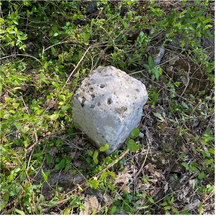
We continued our way and recovered six more monuments, including a crown stone. Crown stones were placed at 5-mile intervals. The detail in the carvings for most of the monuments was noticeably clear, and is a testament to the craftsmanship of the era’s stonecutters.
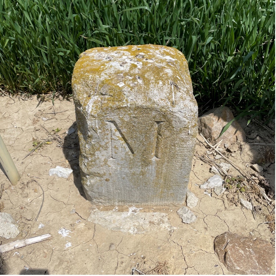
Mason Dixon Stone #95, a crown stone. (Photo: Tim Burch)
While locating these historic monuments, were felt we were standing on hallowed ground. The location of this line was important enough that people, both indigenous and settlers, fought for the right to build their lives there.
This was also a line that would be the site of many battles during the Civil War. Observing these monuments drove home the fact that surveyors play important roles in establishing land ownership both today as well as almost 300 years ago.
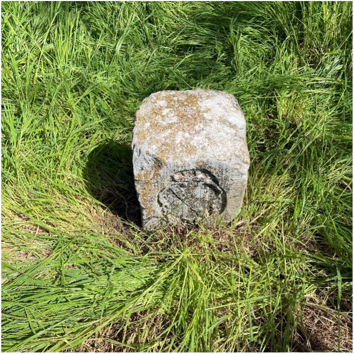
Mason Dixon Stone #93, a Maryland side marking. (Photo: Tim Burch)
Mason and Dixon were pioneers in bringing geodetic astronomy to the American colonies. Their work has provided inspiration for future generations of geospatial professionals, yet most of the public does not know about that portion of their contribution. Hopefully, through the efforts of the “Mason and Dixon Line Preservation Partnership,” we can promote this scientific contribution of Mason and Dixon along with the placement of the boundary stones.
My heartfelt thanks go out to Eric along with Wayne Aubertin and Rob Kundrick (Appalachian Chapter of the Maryland Society of Surveyors) for allowing me to join them for this task. They gave me a chance to be a true surveyor again and connect the past with the future.
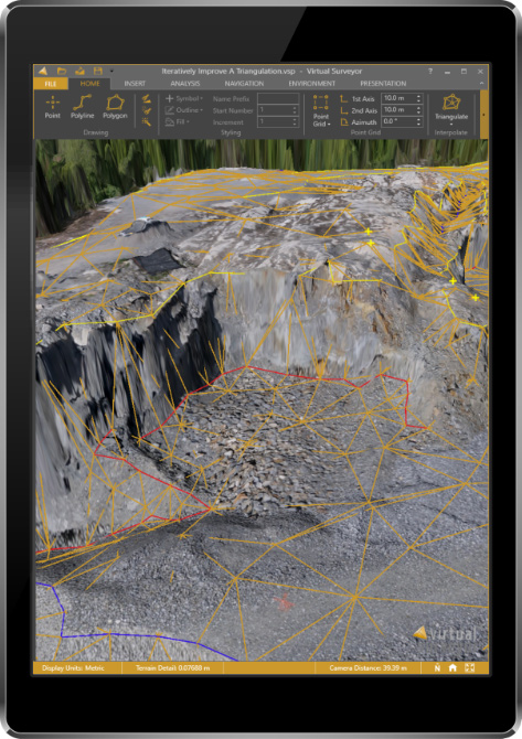
The newly released version 6 of the Virtual Surveyor drone surveying software offers a faster, more efficient workflow and better overall user experience in a more stable platform, according to the software maker.
Version 6 offers new capabilities, an improved licensing system and an extended free application.
“Surveyors who have used the Virtual Surveyor package in the past will be amazed at how easily they can manipulate data and how quickly the software renders results of even the most complex topographies,” said Tom Op ‘t Eyndt, managing director of Virtual Surveyor nv in Belgium.
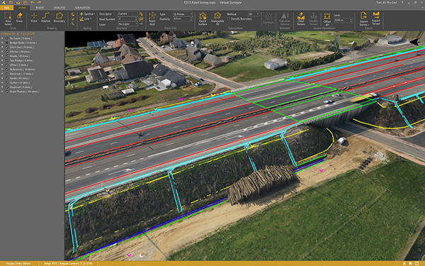
Virtual Surveyor leverages the expertise and interpretation skill of a land surveyor and combines it with the computing power of the computer, the company said.The software generates an interactive onscreen environment through orthophotos and digital surface models, generated from the unmanned aerial vehicle (UAV), where the surveyor selects survey points and breaklines to define the topography.
Image: Virtual Surveyor
Virtual Surveyor enables land surveyors to complement traditional fieldwork with UAV imagery to generate highly accurate topographic products up to five times faster than otherwise possible. It bridges the gap between UAV photogrammetric processing software and engineering computer-aided design (CAD) packages.
“The focus of Version 6 development has been to streamline the workflow — from the importing of drone data to exporting topo information into CAD — to make the surveyor more productive,” Op ‘t Eyndt said.
Key enhancements in Virtual Surveyor 6 include the following:
Easier editing – The new editing functions allows users to quickly select, delete or move individual point and lines placed by the computer during the automated creation of elevation points. The associated Undo/Redo function allows reversing all edit operations.
Better CAD integration – The addition of Descriptor functionality means that point descriptions remain with the point during export to CAD, working the same way as the land surveyor collects data in the field.
3D geometry retained – All points, lines and other data imported into the software, either from a UAV or field surveyed data, retain elevation values and integrate seamlessly into the merged scene. This allows a surveyor, for example, to collect point values from a ditch bottom that may be obscured by vegetation in the drone image and have the bottom points accurately represented in the topography.
Improved drawing tools – Users can now densify (drape) lines and boundaries to map current surface conditions. Individual vertices are now adjustable in all directions and exact X, Y and Z locations can be specified as well. Sub-surface modeling is now possible with these new improvements. Created features can then be exported to CAD for profile or alignment creation.
Extended free plan – Referred to as the Valley version, the free Virtual Surveyor suite has added functionality, including the ability to import photogrammetric data.
Improved licensing – We better honor our principle: “The license follows the user”. With an improved licensing system based on a Virtual Surveyor Identity (email) the user will be able to work where he or she wants.
“The enhanced user experience will continue to appeal to professional land surveyors, who are our core client base,” said Op ‘t Eyndt. “And the seamless integration with CAD and advanced drawing tools will make Virtual Surveyor more attractive to design engineers.”
Virtual Surveyor is available in a free 14-day trial.
Topcon Positioning Group announces the release of the latest addition to its ES total station series in the Americas, the ES-60. Featuring advanced reflectorless capabilities and an upgraded data-transfer functionality — the new ES-60 is designed to provide an entry-level total station option with a fast and powerful EDM.
“The ES-60 is an excellent solution for customers looking for the dependability and accuracy of the ES series in an entry-level package,” said Ray Kerwin, director of global surveying products. “Incorporating all the time-honored expectations of the ES series along with a reflectorless EDM of up to 350 m, and 4000 m with a prism — the instrument also offers a USB option for quick and easy data transfer.”
The ES-60 offers 2- and 5-arc second accuracies. “It’s ideal for land surveying, topography, construction layout, foundations and exterior job sites as well as as-built projects,” said Kerwin.
Additional features include 10,000 points of memory, a battery life of up to 15 hours, dual axis compensation, a waterproof design and a laser pointer.