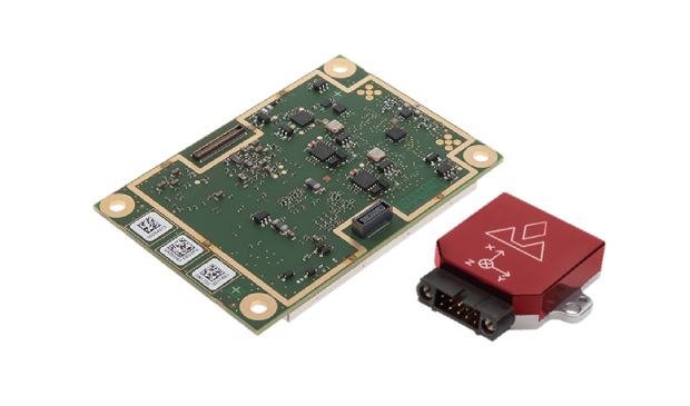
The AsteRx-i combines Septentrio’s latest compact, multi-frequency multi-constellation GNSS engine with an external industrial-grade MEMS-based inertial measurement unit (IMU). It can deliver accurate and reliable GNSS/IMU integrated positioning to the centimeter level as well as full 3D attitude at high update rates and low latency.
Key benefits for users:
IMU-enhanced GNSS positioning with full attitude: heading pitch and roll
AIM+ interference monitoring and mitigation system
High-update rate, low-latency positioning and attitude
Designed around demanding requirements for size, weight and power consumption, the AsteRx-i is suitable for optical inspection and photogrammetry.
Accompanied by a UAS-tailored carrier board, the AsteRx-i integrates seamlessly into light UAVs. The versatility of design and range of connection interfaces extend the AsteRx-i applicability to automation and robotics and as well as logistics.
The AsteRx-i includes Septentrio’s GNSS+ suite of positioning algorithms to convert difficult environments into good positioning: LOCK+ technology to maintain tracking during heavy vibration, APME+ to combat multipath and IONO+ technology to ensure continued position accuracy during periods of elevated ionospheric activity.
It also features AIM+ interference mitigation and monitoring system which can suppress the widest variety of interferers, from simple continuous narrowband signals to the most complex wideband and pulsed jammers.
“Complementing our GNSS portfolio with an INS offering is a natural evolution of our product range. At Septentrio, we design our GNSS solutions with a focus on reliability and availability. Smart integration of inertial sensors builds on these strengths to make affordable high-precision positioning and orientation solutions possible for ever more demanding applications,” said Francesca Clemente, product manager at Septentrio.
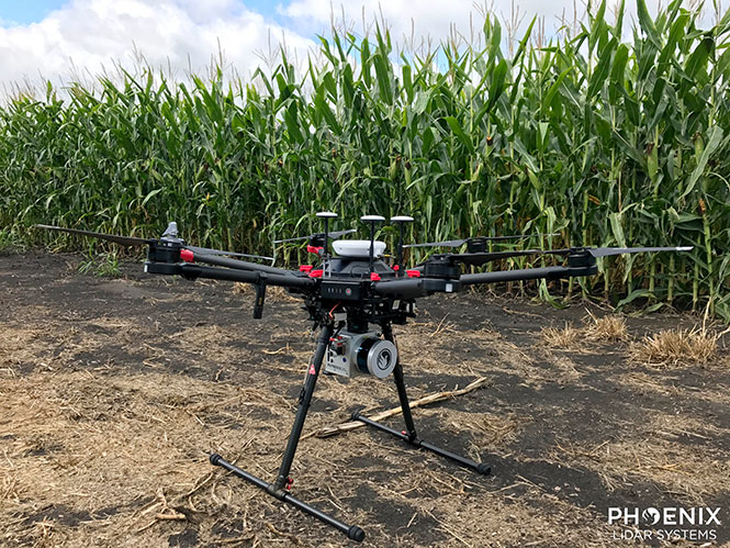
Phoenix Lidar’s Scout System features NovAtel SPAN GNSS/IMU equipment and a pinwheel antenna. Combined with Phoenix’s hardware and software, this lightweight UAV lidar system serves in agriculture, construction and other general mapping applications. Here the Scout is integrated with the DJI M600 Pro UAV. (Photo: Phoenix Lidar Systems)
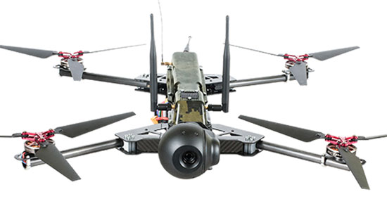
As a UAV flies, it is subject to roll, pitch and yaw movements, adversely affecting the high-definition imagery that industrial-grade UAVs are designed to collect. Three measures combat unwanted movement: a stabilizing gimbal, a high-quality GPS/inertial measurement unit (IMU) integration, and orthorectification of the data during post-processing.
Imaging applications are driving all sectors of the booming UAV market. The increasing availability and variety of compact, robust, lightweight sensors, employing a range of super-resolution and often multi-spectral and hyperspectral technologies, continuously expand and improve UAV applications.
Three companies exhibiting at the Association for Unmanned Vehicle Systems International’s (AUVSI’s) massive Xponential show May 1-3 will showcase recent advances in this arena.
Challenges of Airborne Imaging. Size and weight govern UAV deployment.Imaging sensors must fit compact payload bays. An integrated UAV solution will typically include an imaging sensor, a high-performance GPS/inertial measurement unit (IMU), and a data storage hub to collate streams of data from all connected instruments.
Software geared specifically to flight supplies image orthorectification and manages sensor operation during the mission, enabling users to input GPS coordinates for sensor operation. Outside of defined coordinates, the sensor will not collect data, reducing the amount of data to store or transmit.
Immediate or real-time processing and georeferencing of imaging products has always been key to defense and security applications; it becomes critical for precision agriculture, cartography, civil engineering, remote monitoring and surveillance, intelligent inspection, disaster preparedness and risk study, newsgathering, cinematography, tourism and even commercial advertising. A multisensor landscape view can improve a UAV’s ability to react intelligently without operator input.
Integrated GPS/INS exhibitors at the Xponential show include:
NovAtel (Booth 3219). The company uses a flexible technology platform and diverse OEM products, which include SPAN technology: tightly coupled GNSS receivers with IMUs for reliable, continuously available, position, velocity and attitude, to deliver its vision of assured positioning — anywhere.
NovAtel offers TerraStar Correction Services to provide accurate real-time sub-meter or decimeter positioning around the world, anytime. Its Waypoint Inertial Explorer Xpress post-processing software provides the same core processing and utilities as Inertial Explorer along with simplified functions and workflows tailored for UAV markets and small project areas.
VectorNav (Booth 2214). Engineers at Octopus ISR integrated the VectorNav VN-200 GPS/INS directly into the optical bench of a gimbal to deliver positioning accuracy under flight conditions such as high vibrations, accelerations and temperature fluctuations. The device flies aboard the UAV Factory’s miniature Epsilon series of gyro-stabilized gimbals, enabling the Precision Geo-Lock feature, which combines a GPS-aided inertial navigation system with dedicated software algorithms and payload operator software.
The VN-200 features 16g accelerometers and 2000°/sec gyros in a postage-stamp-sized surface-mount device and a rugged package. Epsilon gyro-stabilized turrets are available with both VectorNav’s VN-200 single GPS-based INS solution and the VN-300 dual GPS-based INS.
SBG Systems (Booth 2535). The company developed specific calibration procedures to provide reliable heading even when UAVs tilt. Magnetometer calibration can be processed in 2D on the ground, or in 3D in flight. Qinertia software enhances inertial navigation systems performance by post processing inertial data with raw GNSS observables.
SBG Systems’ Ellipse 2 Micro high-performance inertial sensors reduces size and costs and for volume projects. It is available as an inertial measurement unit (IMU), or as an attitude and heading reference system (AHRS) or inertial navigation system (INS) running an extended Kalman filter, connected to an external GNSS receiver.
As the days tick down towards the coming AUVSI Xponential convention in Denver April 30 to May 3, new UAV/UAS developments and applications continue to appear, indicating that this industry could be moving from startup into the beginning of a growth phase.
Skycatch and DJI high-precision drones for Komatsu
The construction industry has always been one of the preeminent areas that require medium- to high-precision surveys. And Komatsu has become one of the world’s leaders in machine automation for the construction site.
Now Komatsu has committed to the automation of site surveys using drones, which ultimately appears to be packaged as a turnkey service for construction companies.
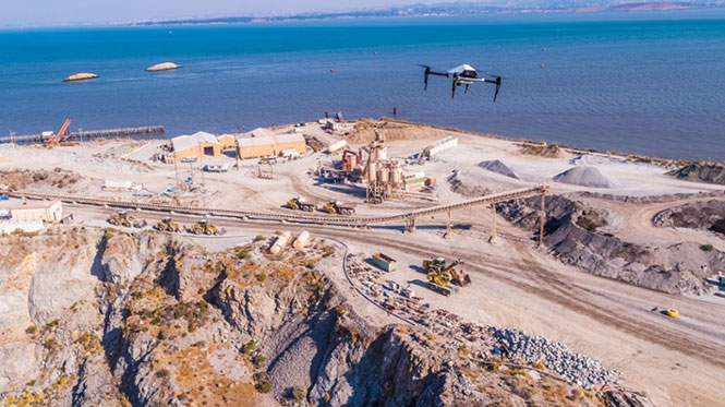
Komatsu aims to show up at a site with all the necessary automated construction machinery and a small staff of automation experts. The experts will survey the site using Skycatch drones and manage the construction for the contractor.
Skycatch drones will survey construction sites with existing RTK networks. (Photo: Skycatch)
Skycatch, based in San Francisco, California, has teamed with Komatsu, who has apparently invested financially in the company and purchased around 1,000 Explore1 drones manufactured by DJI from Skycatch.
Explore1 is actually a modified Matrice 100 DJI drone with special additions. A Skycatch onboard computer links GPS real-time kinematic (RTK) high-precision positioning with a gimbal-mounted 20-megapixel high-resolution camera and the flight computer, resulting in centimeter-level geocoded data.
The big deal is that the system uses existing RTK networks.
Komatsu has been using Skycatch systems for more than three years. The Explore1 system is a combination of all the lessons learned on ease of use and time to collect usable data. Explore1 is used to digitize construction sites during planning, construction and completion.
NASCAR drone protection
It’s unfortunate, but nowadays there always seems to be heightened awareness that events where lots of people gather may present ideal opportunities for possible terrorist attacks. And there has been much made of the possibility that UAVs may be included in the next wave of offensive means for terrorists to inflict civilian casualties on the Western world.
So it’s comforting to hear that for the recent NASCAR race in Fort Worth, Texas, a number of security organizations decided to take the precaution of installing drone countermeasures for the event.
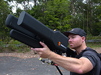
DroneGun, part of the DroneShield anti-UAV system. (Photo: DroneShield)
At the Fort Worth race, the Texas State Department of Public Safety, the Denton County Sheriff, the Fort Worth Police Department, the Texas Forest Service and the Texas Rangers used DroneShield anti-drone systems for the protection of the 2018 Monster Energy NASCAR Cup Series at the Texas Motor Speedway on April 8.
DroneSentinel for drone detection, DroneSentry used for integrated detection and defeat, and DroneGun drone interception were all deployed to determine where drones may be operating and to intercept them if required.
This appears to have been the first known live operational use of all three products by U.S. law enforcement to provide “peace of mind in the aerial domain,” as expressed by an officer about the event.
No bees? Just call for a drone
I’m always frustrated by the fruit tree in my backyard — it absolutely insists on flowering in March when there seems to be more high winds than at any other time of the year, so most of its blossoms are blown to the ground. It’s a mature tree, and you would imagine that it should have learned by now.
But when it is calm and warm, only a few butterflies and birds seem to show any interest. I hardly ever see any bees buzzing around and doing their pollinating thing, and so fruit is hard to come by later in the year.
I’ve thought of borrowing my wife’s make-up brush and dabbing my way round the flowers, but the neighbors, or my wife for that matter, might see me and call the cops to get me taken away…
So I was quite interested when I saw that an outfit called DropCopter, based in Corning, California, is setting about pollination using customized drones. DropCopter basically supplements lost bees by flying over flowering fruit trees and dropping pollen on their blossoms using a drone.
This UAS start-up has initiated a drone pollination service which uses automated multi-rotor drones to dust almonds, pistachios and cherries, boosting crops by up to 15 percent! It seems that fruit producers can rent bees when it comes to pollination time, but bee-rental costs have apparently soared recently. Growers may have been paying up to $180 for one hive to be relocated among their fruit trees. These costs have been cutting into margins and raising the price of fruit at the store.
Enter DropCopter to alleviate pollination problems and restore profit margins for the growers.
DropCopter is using some funding provided by GENIUS NY sponsorship to operate its patent-pending pollination system during nighttime over local New York orchards. Bees don’t like the colder night temperatures, so DropCopter can double the pollination time by operating at night while the bees work the day shift.
But where the heck does DropCopter find all the pollen necessary to fill its pollen distribution containers on its drones? The mystery of fruit pollination still puzzles me.
Range of novel UAV applications grows
So, it’s quite a range of interesting drone applications: automated site survey using drones and a suite of Skycatch processing and data-delivery software; anti-drone protection systems becoming commonplace at larger events; and nature getting a helping hand from pollinating drone systems… Who would have ever thought we’d be seeing these novel, innovative drone solutions?
But, then again, who would have ever expected in the pre-2000 timeframe all the applications that GNSS alone has managed to open up?
Xsens has expanded its MTi product portfolio with the introduction of the MTi-7, a miniature inertial navigation system (INS) module that uses input from an external GNSS receiver to provide an accurate, real-time position, velocity and orientation data stream.
The module has a compact 12 x 12-millimeter footprint, weighs less than 1 gram and consumes under 100 milliwatts, making it suitable for use in space- and power-constrained devices such as drones, as well as autonomous or remote-controlled mapping and imaging equipment.
Image: Xsens
Operating at output data rates up to 800 Hz, the MTi-7 achieves very low latency of 2 milliseconds, allowing for real-time operation of dynamic functions such as flight control and camera stabilization, the company said.
The module also offers a position and velocity output suitable for the navigation of autonomous ground vehicles in sectors such as smart farming and robotics.
The high performance of the MTi-7 is due to the advanced sensor fusion algorithms developed by Xsens to synchronize the inputs from the module’s onboard accelerometer, gyroscope and magnetometer with the signals from an external GNSS receiver or barometer.
The raw sensor signals are combined and processed at high speed in the MTi-7 module to produce a real-time data stream showing the device’s horizontal and vertical position, velocity, roll, pitch and yaw. This user-friendly data stream may be supplied to a host processor via a standard I2C, SPI or UART interface.
Based on the design of the successful MTi 1-series, the MTi-7 offers a straightforward upgrade path for current MTi-1 users on the same form factor. It is also able to provide heading, positioning and orientation accuracy more commonly found in much larger, heavier and higher power devices.
Image: Xsens
:We are seeing exploding demand for accurate control of autonomous or computer-guided equipment such as drones and smart farming ground vehicles,” said Hein Beute, director of product marketing at Xsens. “With its tiny footprint, light weight and low power consumption, the MTi-7 provides the industry’s best solution for any such application that is limited in terms of space or power but that needs a high degree of accuracy and precision in position and orientation data.’
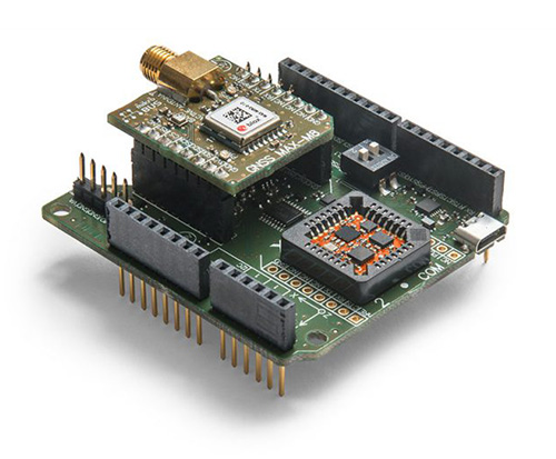
The MTi-7 module is supported by an Arduino-compatible development kit (the MTi-7-DK), which provides access to the module’s I2C, SPI and UART interfaces via micro-USB connections.
Developers can configure the operation of the MTi-7 via the freely available Xsens MT Software Suite. The MT Software Suite includes a GUI for PCs operating on the Linux or Windows platforms, as well as a full Software Development Kit including example source codes and complete documentation.
UASTrakker LLC is offering a new guidance system to enable first responders and maritime rescue units to use fully autonomous drones to help locate people lost at sea or in the wilderness.
The company will showcase the system at AUVSI Xponential, scheduled for April 30-May 4 in Denver, Colorado.
UASTrakker emergency response UAV.
The emergency RF beacon tracking system for drones is based on the company’s core patent-pending technology, which uses an internet of things (IoT) edge computer, running the company’s proprietary software and algorithms to deliver an autonomous search-and-rescue (SAR) solution to the professional end user.
UASTrakker integrated systems using an autonomous drone for locating emergency distress beacons, such as a personal locator beacon (PLB) or man overboard beacon.
The UASTrakker system is capable of locating individuals stranded in floods, lost at sea or on land and is expected to be a key component of rescue efforts in maritime rescue, as well as SAR in the wilderness.
How the system works
Trained users operate the UASTrakker-enabled drone by initiating a flight plan to locate the last known position of the target. Once in the air, the drone will scan the emergency radio frequencies used by PLB beacons in distress, and provide situational awareness to first responders using its thermal, infrared and daytime cameras.
When the target is located, the drone stores the GPS coordinates trail, and has the ability to drop lifesaving rescue supplies, or even lower a winch to a person, and rescue them to safety using a heavy lift drone.Ac
During the entire rescue, UASTrakker streams live video into the company’s cloud computing solution of the entire flight, recording the physical location of the incident in day or nighttime conditions. This enables multi-agency collaboration on SAR missions to help locate the victim.
According to the company, the UASTrakker system is compatible with many off-the-shelf drones, so it can be installed on medium-sized multi-rotors for short missions, a hybrid- electric plane for longer missions, or a heavy lifter for difficult to reach areas and rough weather.
At any time, the user can take over control of the flying of the drone, and activate features like the winch. Cellular/satellite technology offers an almost unlimited range of control.
UASTrakker ground control station.
The UASTrakker company is also developing technology for moving ground control stations, so that drones will land more easily on a ship or moving platform like a SWAT vehicle.
The company’s proprietary artificial intelligence (AI)-capable internet console is expected to provide the pilot in command a first-of-its-kind online search grid, with online tools to initiate the autonomous flight search-and-rescue procedure.
When other first responders have downloaded the UASTrakker app, they will have a collaborative map of the rescue operation, showing the drone position and the location of any emergency PLBs within range, while the drone autonomously locates and surveils them until rescuers can arrive.
“A UASTrakker customized rescue drone can be deployed in many different emergency and disaster situations to locate survivors from maritime accidents, avalanches, hikers in distress or to locate stranded people after a natural disaster like a hurricane or flood, by tracking the PLB that is activated by the person in distress,” said Shawn Holmgren, CTO of UASTrakker.
UASTrakker anticipates interest from government agencies including police, fire and rescue, and military, along with private individuals and commercial businesses.
Holmgren will introduce the system at the Association for Unmanned Vehicle Systems International (AUVSI) Xponential show, booth 3233B. The company expects to launch the UASTrakker system by the hurricane season and summer of 2018.
The first European Drone Summit will take place Oct. 15 in Frankfurt, Germany, to bring together stakeholders to discuss the future of drones in Europe. The summit is sponsored by UAV DACH e.V. and Interaerial Solutions of Intergeo.
In addition to being a smart, up-and-coming technology, commercial drones are also an integral part of the digitalisation of business and society. The EU member states have agreed to introduce legislation regulating the operation of unmanned aircraft in Europe that takes into account both economic potential and safety requirements.
The programme will be put together by UAV DACH experts and will explore legal aspects, technological issues and various application areas. Legislators, industry representatives and user groups will meet on the eve of Europe’s largest trade fair for commercial drones.
The following experts will speak (with more to be named later):
Peter van Blyenburgh, UVSI
Max Scheck, Vereinigung Cockpit
Jules Kneepkens, EASA a.D.
Martin Brandenburg, DJI
Andreas Lamprecht, AIRMAP
Jörg Seebach, DeDrone
UAV DACH is an association for commercial unmanned aviation in Europe. It represents the interests of 175+ corporate members from research, manufacturing and application located in Germany, Austria, Switzerland, Italy, Spain and the Netherlands.
The Interaerial Solutions part of Intergeo is the largest commercial drone trade fair in Europe. It takes place Oct. 16-18, also in Frankfurt.
By Simon Batzdorfer, Markus Bobbe, Martin Becker and Ulf Bestmann, Technische Universitaet Braunschweig
All images courtesy of the authors.
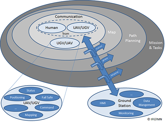
Autonomous vehicles equipped with different environmental sensors, such as optical or thermal camera or a lidar, performed a team survey controlled by a central ground station. The ground station serves as a user interface to define missions and tasks and also to visualize exploration task results online. 2D stitched orthophoto or lidar point clouds are transmitted for display and processing into 3D photogrammetry. Georeferencing data is gathered by an integrated GNSS/IMU positioning system.
In disaster scenarios such as fires, floods or search-and-rescue tasks, good situational awareness is indispensable for responders coping with a complex and often chaotic environment. In most cases, a prior known map data are outdated, and an efficient situational proceeding such as path planning or creation of a search pattern cannot be performed. This information can often only be gathered by manned exploration using ground or airborne systems, with limits on availability.
The research project Automated Navigation and Communication for Exploration (ANKommEn) seeks to create an automated unmanned system to close this gap by providing up-to-date scenario information while increasing the safety of human resources, using unmanned aerial (UAV) and ground-based (UGV) vehicles.
To provide up-to-date information of the desired destination area, all vehicles are equipped with identical positioning and communication hardware complemented by diverse sensors (RGB camera, infrared [IR] camera, lidar) for visual exploration. The visual sensor information is transmitted to a central ground station for visualization and/or analysis. To increase the advantages of the system, the unmanned systems should have a high grade of automation to reduce the workload of the operator so that only basic inputs have to be done by the operator. For example, just by marking a destination area and choosing a predefined task, the mission will be planned automatically, and after the corresponding waypoint-list has been transmitted to the vehicles, the mission will start.
Automated procedures of a UAV in particular require valid position information related to accuracy, availability and continuity. In exploration areas where the UAV operates in low altitude or using a UGV, the reception of the GNSS signal can be degraded by the topology (buildings and such). Using more than one GNSS can increase the availability of position information. Vehicle control, georeferencing environmental sensor data and exploration results all require high-frequency absolute position and attitude and heading information. This data is gathered by fusing GNSS and inertial measurment unit (IMU) data.
OVERALL SYSTEM DESIGN
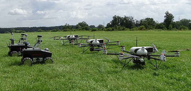
The overall system consists of three UAVs, two UGVs (Opening photo) and a central ground control station. The latter serves as a central human-machine interface to monitor and manage cooperative operation of the UAVs/UGVs by an operator. Based on a priori known map data, exploration areas and tasks are defined and assigned to the UAVs/UGVs and will be updated with actual information of the visual sensors while performing a mission.
Figure 1 shows the interaction and information exchange between the different vehicles and sensors.
Figure 1. Diagram of interaction and information exchange.
All UAVs/UGVs are equipped with a navigation and communication unit (NAV/COM) and an environmental sensor payload (ENV) unit, including an RGB camera, thermal camera or a lidar respectively.
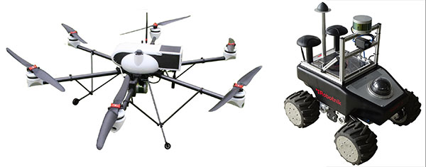
UAV/UGV and Sensor Hardware. The UAVs carry a payload of 2.7 kg (NAV/COM unit, mounted in the upper compartment, and ENV unit mounted under the UAV) and a flight time of up to 30 minutes (Figure 2, left). The payload sensors are carried and stabilized by a two-axis-gimbal. The environmental sensor payload unit is based on three different types of sensors, which are interchangeable between the different UAVs: RGB camera, lidar and IR camera.
For ground-based exploration, two four-wheel-drive UGVs carry a pan-tilt-zoom (PTZ) camera at the top of front chassis (Figure 2, right), and are equipped with a lidar and a thermal camera, or a stereo RGB camera, respectively.
Figure 2. UAV carrying a lidar (left) and UGV carrying lidar and IR camera (right).
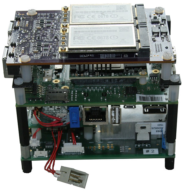
The navigation and communication unit mounted as a stack includes a network processor board for communication and data exchange between the UAV/UGV and the central ground and control station. An embedded processing board provides position calculation and GNSS-NTP-based time server. Data for the position calculation is provided by a custom-designed break-out-board (Figure 3).
Figure 3. Navigation and communication unit.
Data traced by these sensors cannot be sent directly to the ground station because of the huge data amount and the limited bandwidth of the communication link. Therefore, data from the sensors are preprocessed or compressed on a small form-factor personal computer and then transmitted to the ground station.
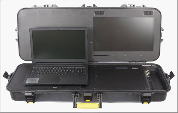
Ground Station. The ground station is the central device for command, control and visualization of the total system. It provides several options to display the data from the sensors and vehicles and a combination of them, and also provides automated path planning and calculation of the 3D reconstruction (photogrammetry) and online 2D stitched orthophoto.
Software Frameworks. The basic software for determining the vehicle’s state in 3D position, velocity, attitude and heading is established within a modular navigation software framework, with the option to process data of different sensors in real time as well as post-processing for data evaluation and development purposes. Several algorithms for sensor data fusion are implemented. The algorithm for IMU/GNSS fusion is based on an extended Kalman filter and also provides an IMU data-based state vector, stabilized by GNSS information, for the visual sensors. This state vector is published by using the robot operating system (ROS), a framework for inter-process communication based on a TCP or UDP publisher/subscriber concept. The visual sensors and embedded PCs subscribe to different ROS messages, for example, the state-vector-message or information of other sensors.
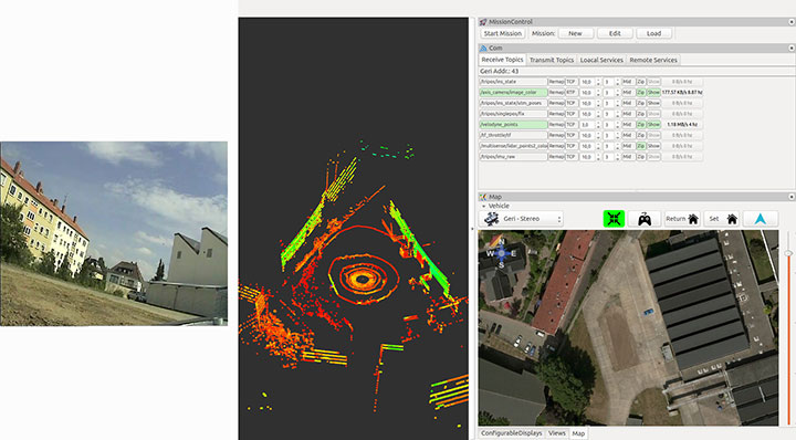
Figure 4 shows examples of the actual camera view from the UGV, and point cloulds and map generated by the UAV. The software layout can be customized by the user.
Figure 4. From left to right: the actual view by the PTZ camera onboard the UGV, the point cloud gathered by the UAV’s lidar, and the mission parameters and map of an aerial view.
POSITIONING OF UAV AND UGV
Automated operation of UGVs and UAVs requires valid position as well as attitude and heading information. In the case of using only one GNSS, signal quality and availability can be degraded by the environment (buildings) and can result in less precise or even a lack of position information.
GNSS Multi-Constellation. To overcome the risk of poor availability of GNSS-based position information, parallel usage of different GNSS can raise the number of received satellite signals: GPS, GLONASS, the evolving Galileo and BeiDou. When using a multi-constellation approach for positioning, one has to take care of several differing aspects between the GNSS. Each system uses a different geodetic reference frame and time basis. Measurements gathered from another GNSS system must be transformed into the reference frame of the desired system. The geometric distribution of the satellites is improved by using more than one GNSS constellation, indicated by a lower dilution-of-precision value.
The navigation software framework is designed for real-time computation and also for post-processing. In post-processing, the recorded sensor data is streamed to the software framework with the option of changing several parameters and settings for calculation. One option is to exclude satellites at low elevation from position calculation by changing the cut-off elevation for these satellites. This parameter will be changed to simulate environmental conditions that block receiving GNSS signals, like buildings within urban scenarios, to compare the availability of received GNSS signals for single- and multi-constellation-based position calculation.
Recorded data of a real-world test serves as the database for the post-processing with different cut-off elevation parameters. At the beginning of the field test, there was a short initialization period to boot the OS and to start basic processes for positioning. After that, a predefined mission was flown and the GNSS measurements have been saved for the described post-processing.
Post-processing has been performed with different cut-off elevation parameters of 5° up to 35°. In the case of 35°, the number of GPS satellites is reduced to the minimum for position calculation of four, in contrast to 5–7 available satellites for a multi-constellation based solution.
GNSS/IMU Fusion. Using the GNSS multi-constellation approach can increase availability of position information. For attitude and heading determination, an IMU is nevertheless indispensable. Additionally, the frequency of the pure GNSS-based positioning information is usually between 1 Hz to 5 Hz within the described hardware setup. Meaningful georeferencing of the environmental sensors requires much higher frequency position and attitude information.
The IMU provides high-frequency 3D measurements of accelerations and angular rates. Using common strapdown algorithm processing, high-frequency position, velocity, attitude and heading information is provided in real time. Due to the short time stability of pure inertial navigation, the GNSS positioning results are used for aiding purposes within the Kalman filter’s update step. To overcome the absence of GNSS aiding information even when using multi-constellations, there are mainly two options. First, a short coasting period is possible after the data fusion has reached a steady state.
Second, due to the highly modularly design of the navigation software framework, it is possible to use position or attitude increments from environmental sensor data processing for aiding the IMU.
The vehicle’s state vector is then distributed with high frequency within the system for georeferencing measurements of the environmental sensors, especially the RGB camera and the lidar for photogrammetry and simultaneous location and mapping (SLAM) applications.
PHOTOGRAMMETRY AND SLAM
In major fire scenarios, maps can be out of date. Therefore, techniques have been developed to gather a 2D overview based on several single RGB pictures taken and processed on board a UAV and transmitted to the ground station via data links. Additional processing of a 3D reconstruction of the scenario is an integrated feature within the ground station. Both approaches were implemented to get an automated rapid aerial mapping solution.
In the case of the 2D overview, SLAM algorithms, often used in robotic research, are adapted for this specific use case. These algorithms provide good results for a rapid aerial mapping solution to get an overview of the scenario, because the map is updated incrementally with every new image, but they are less precise, which can be compensated for by using the photogrammetric 3D reconstruction. The live mapping (SLAM) approach is based on the ORB-SLAM algorithm, and the photogrammetry-based approach uses commercially available photogrammetry software.
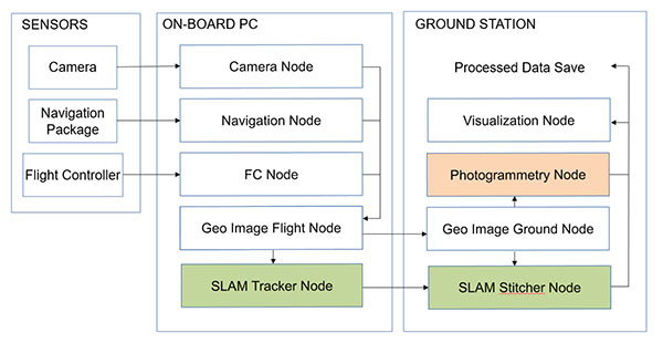
The systems, on the UAV for 2D and for 3D on the ground station, use the ROS framework for processing the visual sensor data and the described techniques for positioning, georeferencing and attitude determination. For data exchange between these frameworks, several software interfaces have been implemented. Figure 5 displays a flowchart of the implemented workflow.
The sensor/input data is received by corresponding nodes on the aerial vehicle. After adding the camera pose information to the image in the geo-image flight node, the image is sent to the geo-image ground node on the ground station. The SLAM process is separated into two parts. The SLAM tracker node calculates the transformation between images, and the SLAM stitcher node applies the transformations. The transformed images are displayed by the visualization node. The photogrammetry node receives the georeferenced images, stores the data, and initiates the photogrammetric processing once the survey is finished. The results can also be displayed by the visualization node and exported in a desired format.
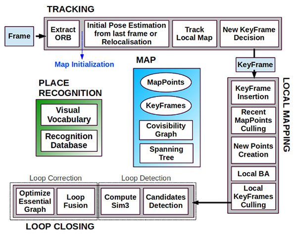
Visual SLAM. Computer vision-based algorithms have developed rapidly over the last few years. One method estimates a pose by using monocular image processing, known as parallel tracking and mapping (PTAM). This integrates a bundle adjustment and separates the tracking and the mapping procedure into different threads, leading to a real-time capable framework. These basic PTAM principles have been integrated into a robust loop-closing and another method of relocalization, known as Oriented FAST and Rotated BRIEF (ORB SLAM), shown in Figure 6. Here, tracking, local mapping and loop closing are separated into different threads (gray boxes), with the main map and place recognition in the middle.
Figure 6. ORB SLAM system overview [Mur-Artal, 2015].The tracking thread predicts the current pose from the last known position and movement by using a constant velocity model and performs a guided search of map points. If these points are found near the estimated position, the velocity model is valid and the tracking procedure continues. Otherwise, the tracking is lost and a relocalization in the global map starts by using a subset of features, which are increased after detection of corresponding features in other keyframes to optimize the camera pose and, finally, the tracking procedure continues. The last step of this procedure is to decide whether the current frame contains enough information to be inserted as a new keyframe for further calculations.
To mark a frame as a new keyframe, the frame must fulfill all of the following conditions:
More than minimum number of frames has passed.
Local mapping is on idle or condition 1 fulfilled.
A minimum number of 50 points is observed.
A maximum of 90% of the features is already observed by the other frames.
When a new keyframe is passed to the local mapping procedure and inserted as a node into a co-visibility graph structure, new correspondences are searched in the connected keyframes to triangulate new points. Based on the information accumulated during the tracking, a point culling keeps only high-quality points in the map as well as a culling of redundant keyframes.
Then a loop closing is performed. This is one of the main improvements compared to PTAM. If a loop is detected, the drift accumulated in the loop is computed, and both sides of the loop are aligned and visible points are fused. In a final step, a pose graph optimization is done to achieve global consistency.
This information of the 3D camera pose is used to generate a 2D orthophoto in real time while the vehicle is flying. To create a 2D orthophoto, a common reference frame is approximated, which is orthogonal to all camera measurements. The projection is performed by using a projection model based on a pinhole camera.
After the compensation and distortion, the whole image can be stitched to the current global map.
Photogrammetry. This approach uses off-the-shelf photogrammetric processing software. The processing is triggered automatically when the survey is completed and all images are transferred to the ground station via data link. For georeferencing of the images, the camera location and the inner camera geometry were written to the EXIF file of each image by the geo-image ground node (Figure 5). To ensure an acceptable compromise between orthophoto quality and the required processing time, an analysis regarding the impact of the most relevant processing parameters has been performed.
Figure 5. ROS node layout with SLAM (green) and photogrammetry workflow (red).
The photogrammetry process consists of four steps:
camera alignment (optimizing the homographic equation)
mesh creation by generated tie points
orthophoto creation (dense cloud or digital elevation model)
export.
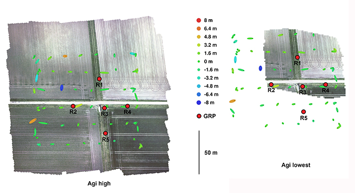
Analyses and Evaluation. To evaluate the correct workflow of both approaches of 2D live-stitching and the 3D photogrammetry, a real-world flight test above agricultural cropland has been performed. The results of both approaches are shown in Figure 7 and Figure 8. Generally, agricultural cropland and its mean textured surface pose a challenge for mapping processes because of the limited number of trackable features.
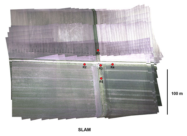
Figure 7. Orthophotos created with the profiles high and lowest (including ground reference points).Figure 8. Orthophotos created with 2D live stitching approach of cropland.
Four predefined profiles were used to cover the requirement of compromise between processing duration and quality of the generated orthophoto. Each profile level generates a corresponding level of alignment accuracy and mesh face count: lowest, low, medium and high.
To estimate the accuracy of the created maps by the different profiles, five ground reference points (GRPs) were distributed over the mission area. The location of the GRPs was determined using a RTK-GNSS system leading to a horizontal RMSE below 2 cm. To enable robust processing for this scenario, the overlap and the sidelap was chosen to be 70%. A ground-sampling distance (GSD) of 2 cm was needed to identify the GRPs. This resulted in a mission consisting of six times 100-meter (m) lines with a distance of 25 m in an altitude of 60 m over ground. During the flight time of 4.5 minutes, 271 images were taken.
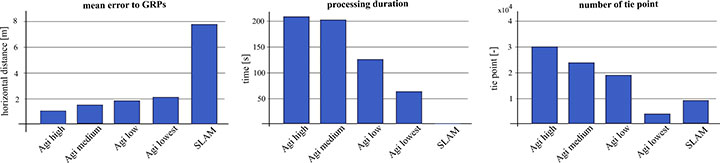
To compare the profiles, they were triggered one after another with the same set of images. The created results are shown in Figure 7. All profiles resulted in consistent solutions and were successfully georeferenced. The map based on the lowest profile could not recreate the complete area (Figure 7, right). The remaining profiles led to similar results without notable differences to visual inspection. The processing time varied between 1.2 and 3.6 minutes. A comparison of this and other criteria is given in Figure 9.
Figure 9. Evaluation and comparison of defined software profiles and visual SLAM.
The created final image of the SLAM pipeline is shown in Figure 8. The image was updated with every new image and was therefore finished before the UAV landed. The mean location error measured using the reference points was about 8 m, significantly larger than the errors observed in the photogrammetry results. In Figure 9 the results are contrasted to the results of the photogrammetry approach.
While the mean error in the low profile is half as high as in the lowest profile, the calculated errors using the medium and high profiles are not enhanced significantly. The number of tie points created by the lowest profile is an order a magnitude lower compared to the other three profiles.
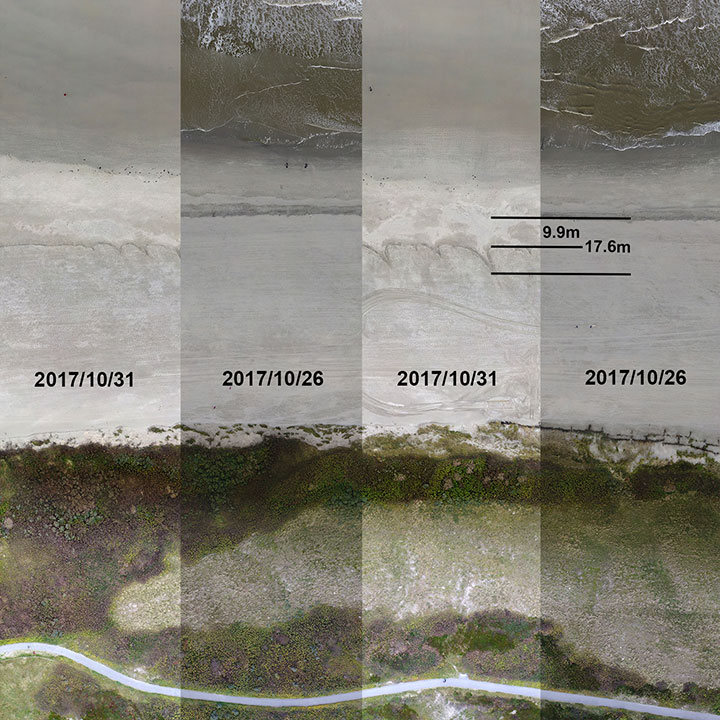
We conducted flight tests on Langeoog island in the North Sea, to gather information on efforts to protect the island’s coastline from water erosion. For this reason, sand was selectively washed up to the coastline by dredgers at the beginning of October 2017. Between Oct. 26 and 31, due to severe weather with a storm flood, a huge erosion of the washed up sand occurred, and the result is shown in Figure 10. The level of erosion was determined by comparison of the orthophoto of the same area. The dislocation averaged out to 9.9 m with some peaks up to 17.6 m.
Figure 10. Evaluation of erosion.
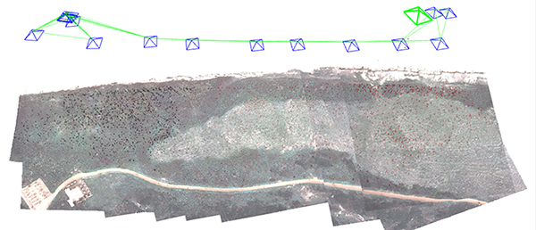
The 3D photogrammetry provides a more detailed image compared to the image of the 2D-live-stitching approach (Figure 11), but both approaches can provide the desired information of the area.
Figure 11. Result of the SLAM approach with camera poses and tracked features.
Both implemented approaches were successfully integrated to get the desired fully automated rapid aerial mapping solution. This also includes the basic tasks of the automated mission planning, camera control, image transport to ground station, automated processing and the visualization of the results.
CONCLUSION
The benefits of multi-constellation GNSS positioning have been demonstrated with a focus on UAVs and UGVs operating in catastrophic scenarios, especially where GNSS signal reception might be blocked. This position information is also used for georeferencing of images and visual reconstruction of the area. The overall system has demonstrated the capability of an automated orthophoto generation. Both implemented mapping methods — a 2D live stitching and a 3D photogrammetry — provided results that fulfill the requirements to get an instantaneous 2D overview and a contemporary 3D reconstruction of the area.
ACKNOWLEDGMENTS
This work was done within the joint research project ANKommEn, funded by the German Federal Ministry of Economic Affairs and Energy, administered by the Space Administration of the DLR (funding code: 50NA1518). Project partners are the Institute of Flight Guidance (IFF), the Institute of Mobile Machines and Commercial Vehicles (IMN) — both part of Technische Universität Braunschweig — and AirRobot GmbH & Co. KG, a German manufacturer of multirotor UAVs. The professional fire brigade of Braunschweig and the Lower Saxony Water Management, Coastal Defense and Nature Conservation Agency also participate as associated project partners.
SIMON BATZDORFER holds a Dipl.-Ing. in mechanical engineering and is a research engineer at the Technische Universitaet Braunschweig, Institute of Flight Guidance (IFF).
MARKUS BOBBE holds a M.Sc. in aerospace engineering and is a research engineer at the Braunschweig IFF.
MARTIN BECKER holds a Dipl.-Ing. in aerospace engineering and is a research engineer at the Braunschweig IFF.
ULF BESTMANN received his Dr.-Ing. in mechanical engineering from TU Braunschweig. He is head of the navigation department of the IFF. He co-founded the company messWERK GmbH, a service provider in flight testing and certification.
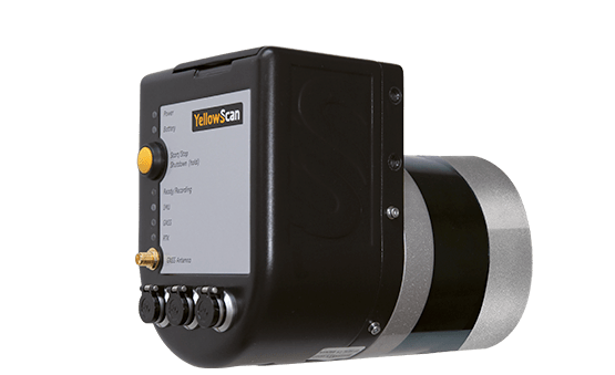
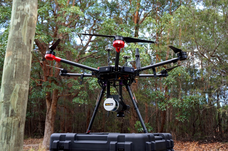
YellowScan has launched a new lidar system, the Surveyor Ultra. It integrates the Velodyne VLP-32C scanner and the Applanix APX-15 GNSS/inertial measurement unit (IMU).
With high density (600,000 shots per second), the system is suitable for high-speed UAVs and long-range needs (maximum range: 100 meters). Its light weight (1.7 kg) makes it easy to mount on any drone, including vertical takeoff and landing (VTOL) UAVs.
As for all YellowScan lidar systems, the Surveyor Ultra is a turn-key system fitted for under vegetation 3D modeling and fast data processing, the company said.
Applications such as forestry, archeology and environmental research will benefit from Surveyor Ultra, as they require long-endurance flights high above trees or over rocky mountains and rugged terrain.
“The Surveyor Ultra shows great potential to safely and efficiently operate lidar on lightweight fixed-wing UAVs,” said Tristan Allouis, YellowScan CTO. “The Surveyor Ultra completes our product line, including the successful Surveyor Lidar System (integration of the VLP-16 scanner from Velodyne).”
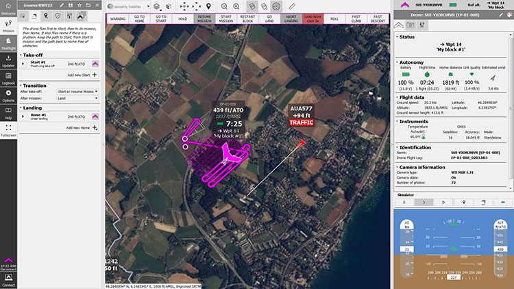
SenseFly is partnering with Trimble to optimize the drone mapping workflow for geospatial professionals.
The new integration is designed to ensure a smooth end-to-end mapping drone workflow. senseFly operators can now, within the recently launched eMotion 3.5 software, transform a senseFly S.O.D.A. camera’s georeferenced imagery into an automatically collated project (in .jxl format).
This enables the one-click import of drone imagery into the Trimble Business Center Aerial Photogrammetry module without the need for manual project creation and organization of images.
The senseFly-to-Trimble mapping workflow includes:
planning and monitoring a senseFly S.O.D.A.-based drone flight (in eMotion 3.5)
downloading the drone’s images for one-click georeferencing in eMotion 3.5 (Flight Data Manager)
clicking to create a .jxl format mapping project
opening a project within the Trimble Business Center Aerial Photogrammetry module
processing the drone’s imagery to generate orthophotos, contour maps, point clouds, digital surface models (DSMs) and feature maps
analyzing and acting upon the data.
Screenshot: Trimble
“Making work easier and more efficient for geospatial professionals is the goal that drives every solution we develop,” said Jean-Christophe Zufferey, senseFly co-founder and CEO. “Therefore, we are excited to collaborate with Trimble on more tightly integrating our solutions, since enhancements such as this new eMotion-to-Trimble Business Center workflow do exactly that, ensuring that the transition from data collection to acting upon this data is as seamless as possible.”
The senseFly S.O.D.A. is built for professional drone photogrammetry work. The 1-inch, 20-megapixel RGB camera captures sharp aerial images across a range of light conditions, allowing senseFly fixed-wing drone operators to produce detailed, vivid orthomosaics and ultra-accurate 3D digital surface models.
senseFly S.O.D.A. is compatible with most senseFly fixed-wing mapping drones, including the large-coverage eBee Plus.
Trimble Business Center allows surveyors and other geospatial professionals to combine aerial photography with data collected from GNSS receivers, total stations, 3D laser scanners and more, for a complete field-to-finish workflow. By combining imagery from unmanned aerial systems with ground-based survey data, users can visualize their project from both aerial and terrestrial perspectives, measure points within the images and create 3D models of the infrastructure and terrain.
According to AUVSI, the experts will present keynotes devoted to themes critical to the advancement and growth of unmanned systems.
On Tuesday, May 1, the Massachusetts Institute of Technology’s David Autor and PrecisionHawk’s Michael Chasen will highlight how unmanned systems are changing the way we work and how technology is influencing different industries.
On Wednesday, May 2, the University of North Carolina’s Zeynep Tufekci, Lockheed Martin’s Stephanie Hill and UPS’ Eduardo Martinez will explore the cross section between technology and society. This keynote will also cover the emergence of artificial intelligence, unmanned systems and robotics in the military, and the automated delivery of medication and vaccines to remote areas around the globe.
Finally, on Thursday, May 3, Northrop Grumman’s Chris Hernandez, as well as a panel, will discuss the humanitarian and public safety applications of unmanned systems to provide aid and support.
The panel will consist of the National Council on Public Safety UAS’ Charles L. Werner, Texas A&M University’s Robin Murphy, the Alameda County (California) Sheriff’s Office’s Thomas Madigan and the Colorado Division of Fire Prevention and Control’s Mike Morgan.
“We are pleased to welcome this exceptional line-up of experts to keynote the themed sessions at Xponential 2018,” said Brian Wynne, AUVSI president and CEO. “These outstanding speakers will enhance Xponential’s educational programming by lending their expertise, experience and unique perspective in unmanned systems, giving attendees a priceless opportunity to apply critical learning to real-life business challenges.”
Tony Murfin Contributing Editor, Professional OEM & UAV, GPS World
As the days tick down towards the always-anticipated Association for Unmanned Vehicle Systems International (AUVSI) Xponential convention in Denver May 1-3, the unmanned vehicle industry is preparing once more for one of its largest exhibitions.
More than 750 exhibitors will be spread over a huge 370,000-square-foot exhibit floor at the Colorado Convention Center and 8,500 visitors from unmanned systems and robotics are expected to come to share ideas, gain insights and carefully examine the unmanned innovations on show.
STEM Outreach. This year the show will not only feature industry innovation and growth, but will also highlight resources for potential science, technology, engineering and math (STEM) graduates with interactive and engaging content, including:
A buildathon/hackathon to conceive, design and build inventions during a timed competition prior to Xponential. Final projects will be displayed on the Xponential show floor as a representation of innovation and collaboration.
A dedicated area in the Xponential exhibit hall will describe the STEM education programs and services supported by AUVSI and the AUVSI Foundation to foster and cultivate the next generation of innovators and leaders.
An area of the show floor will also showcase the winners of student robotics competitions.
Denver area high school students will be invited to tour the exhibit area to introduce them to emerging unmanned technologies and applications.
A reception at the show promises to mix young professionals in unmanned systems with seasoned industry leaders, and finally,
The Women and Diversity in Robotics forum will feature speed networking with leaders to review STEM opportunities for career-focused women and girls.
Survive and Thrive. Meanwhile, the Denver exhibition will demonstrate how the rapidly evolving world of UAVs has encouraged “survive and thrive” for those new entrants who together seem to have adapted to address almost any and all opportunities. We’ll mention a couple of examples here, and attempt to provide a better cross section of the huge number of companies and products present following the actual show.
For instance, one of the drawbacks for small, predominantly electric-powered, multi-rotor UAVs is that their endurance is limited. Providing longer duration operations may be outside their envelope — for such longer term things as providing temporary mobile-phone signal coverage, or police/agency reconnaissance/search, or for larger vertical inspection jobs.
Presumably, floating one of several available models of lighter-than-air, blimp-type UAVs might be more expensive or cumbersome than using a multi-rotor unmanned vehicle, so overcoming power-supply issues would seem to be key. One way to do this is to attach a strong tether bringing power up from the ground.
Orion UAS. The Elistair (France) Orion UAS will no doubt be featured on the company’s booth. This multi-rotor UAV has been developed for longer term aerial surveillance and telecommunications operations. Typical users include law enforcement, private and public safety, national security, asset protection, emergency communications and crisis management, so these tethered drones are deployed by police forces, public security departments, public and private security companies, and governments in more than 30 countries.
Photo: Elistair
The Orion UAS uses industrial components and system redundancy, including autopilot sensors, motors, power distribution and logic controls, and has an emergency parachute system. The patented micro-tether system ensures a stable platform supplied with continuous power from the ground to enable up to 10 hours of endurance. The mechanical structure of the drone is designed to sustain strong winds with maximum stability. With system redundancies and automated emergency procedures, the user is able to focus on safety-critical missions and data collection, while the risk of human mistakes is reduced.
The onboard camera has both FLIR and optical, enabling night/day surveillance with gimbal stabilization and low latency — the 30x optical zoom makes it possible to detect a moving person from kilometers away. And the tether system provides high-speed, interference-free data transmission so the system is also virtually undetectable. It’s easy to see why tethered drones are becoming more popular for security applications.
Identifying UAVs. At the FAA Unmanned Aircraft Systems (UAS) Symposium last week in Baltimore, a key issue discussed concerned remote identification and tracking of drones. It would seem that the FAA is about to announce a new rule that could eventually clear the way for drones flying over people and beyond line-of-sight of their operators — and this may be a key topic of discussion at Xponential.
The FAA rule appears to mandate that every drone should in some way communicate its identification — presumably its FAA registration ID — so that its operator could also be known.
One well-known company, Ford, has already announced that it has a concept using onboard collision lights on a drone to optically signal the 10-digit FAA registration number to the ground for capture and decoding. Maybe other exhibitors at the show will have other solutions — perhaps radio based? We’ll see.
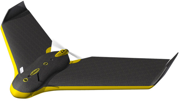
Sensefly eBee drone.
Sensefly’s eBee. At the sensefly booth, we may also hear about several interesting announcements on recent drone applications:
Products on display will include the RTK/PPK-enabled eBee Plus professional mapping drone, the eBee SQ drone for agricultural applications and the albris mapping and inspection drone, as well as the senseFly S.O.D.A camera and GeoBase.
In addition, senseFly sales manager and GIS scientist Briton Voorhees will deliver a presentation titled, “Comparing workflow and point cloud outputs of the Trimble SX10 TLS and senseFly eBee Plus drone,” on Wednesday, May 2, at 11 a.m. in the Mapping and Surveying Track.
Booth visitors can also find out more about senseFly’s comprehensive 360 solutions, which are designed to improve operational efficiencies and support decision-making in the surveying, mining and quarries, agriculture and inspection sectors.
And many more. GNSS players also expected to be at the show include Hemisphere GNSS, NovAtel, Rockwell-Collins, Septentrio, Tersus, Trimble, Accord/Aspen Avionics, Comnav, Navtech, Swift and Topcon, as well as GNSS chip manufacturers u-blox and Intel — although Intel may likely focus on its UAV/communications offerings at this show.
There will also be a number of antenna suppliers, inertial sensor manufacturers, UAV autopilot manufacturers and several ancillary electronics and mechanical systems suppliers — all trying to solidify their positions in the UAV vehicle and systems integration supply chain.
The major focus, as usual, will be on UAV/UAS vehicle manufacturers and system integrators and their products — there is always a great exhibition of actual UAVs from all sectors of the industry.
So, along with a parallel program of educational presentations on a wide range of industry aspects, the AUVSI Xponential convention promises to have plenty of opportunities to find things of interest to almost anyone, and many areas to focus on for experts already in the industry.
MicroPilot is working with Simlat to develop a pan, tilt and zoom payload simulation tool to help improve the camera-centric parts of MicroPilot’s autopilot software.
Simlat is a provider of training systems for UAVs, enabling training on any platform with any payload for any mission. The tool Simlat has developed emulates a camera payload on a UAV, including simulated video, when set up with an “iron bird.”
This allows more testing to be performed on the ground, and potential problems with the payload worked out before flight testing begins.
“Flight testing is time consuming and expensive and simulation is an essential tool that reduces the amount of flight testing necessary to bring a drone to market,” said Howard Loewen, president of MicroPilot. “We are pleased to be working with Simlat to add this capability to our software development process.
“MicroPilot is always looking for useful tools and features to integrate with our products in order to help deliver more capable and reliable products to our customers. This camera payload emulator is just one of many third-party tools we have incorporated into our testing and development and yet another way MicroPilot has shown its dedication to product quality and performance.”
MicroPilot is an ISO 9001 autopilot manufacturer to bring to market an ISO 9001 sub-30-gram autopilot, triple redundant autopilot, and full-function general-purpose autopilot. MicroPilot offers a family of lightweight UAV autopilots that can fly fixed-wing, transitional, helicopter and multirotor UAVs.
 Key benefits for users: