After a comprehensive risk analysis, the U.S. Federal Aviation Administration (FAA) has raised the unmanned aircraft (UAS) “blanket” altitude authorization for Section 333 exemption holders and government aircraft operators to 400 feet. Previously, the agency had put in place a nationwide Certificate of Waiver or Authorization (COA) for such flights up to 200 feet.
The new COA policy allows small unmanned aircraft — operated as other than model aircraft (i.e. commercial use) — to fly up to 400 feet anywhere in the country except restricted airspace and other areas, such as major cities, where the agency prohibits UAS operations.
“This is another milestone in our effort to change the traditional speed of government,” said FAA Administrator Michael Huerta. “Expanding the authorized airspace for these operations means government and industry can carry out unmanned aircraft missions more quickly and with less red tape.”
The FAA expects the move will reduce the workload for COA applications for industry UAS operators, government agencies and the FAA’s Air Traffic Organization. The agency also estimates the move will lessen the need for individual COAs by 30 to 40 percent. Other provisions of an FAA authorization, such as registering the UAS and making sure pilots have the proper certification, still apply.
Under the blanket COA, the FAA will permit flights at or below 400 feet for UAS operators with a Section 333 exemption for aircraft weighing less than 55 pounds and for government UAS operations. Operators must fly under daytime Visual Flight Rules, keep the UAS within visual line of sight of the pilot and stay certain distances away from airports or heliports:
Five nautical miles (NM) from an airport having an operational control tower; or
Three NM from an airport with a published instrument flight procedure, but not an operational tower; or
Two NM from an airport without a published instrument flight procedure or an operational tower; or
Two NM from a heliport with a published instrument flight procedure.
AUVSI releases statement
“The FAA’s decision to raise the operating altitude of the blanket COA from 200 feet to 400 feet provides greater flexibility to those receiving FAA exemptions and makes it easier for more commercial UAS operators to access the skies,” said Brian Wynne, president and CEO of the Association for Unmanned Vehicle Systems International (AUVSI), in a statement. “While regulation by exemption is not a long-term solution for the many industries waiting to operate UAS for commercial purposes, this is another positive step toward the overall integration of UAS into the NAS.
“However, the FAA still needs to finalize its small UAS rule as quickly as possible to allow anyone who follows the rule to fly. The new blanket COA altitude remains lower than the operating ceiling of 500 feet proposed in the small UAS rule. In addition, other requirements for UAS operators under the Section 333 exemption process are more onerous than those contemplated in the proposed rule.
“The UAS industry is poised to be one of the fastest-growing in American history, and we urge the FAA to finalize the small UAS rule without further delay so this technology can truly take off.”
In May 2014, the FAA announced it would consider granting exemptions for certain low-risk commercial UAS applications under Section 333 of the FAA Modernization and Reform Act of 2012. The agency began granting exemptions in September 2014. To date, the FAA has granted more than 4,200 exemptions.
According to AUVSI’s report on the first 1,000 exemptions, businesses in more than 25 industries representing more than 600,000 jobs and $500 billion in economic impact now are using UAS technology. The full report can be found here.
The unmanned aerial vehicle (UAVs) sector is a dynamic GNSS-enabled sector globally and Europe is no exception. In January I attended a UAV event at the Royal Military Academy in Brussels. The focus of the two-day meeting was on small commercial and recreational remotely piloted aircraft systems (RPAS) that are rapidly populating Europe’s airspace.
Currently, there is no European legislation that governs their use in conjunction with general aviation and, typically, national legislation varies across the member states. Regulators are trying to play catch-up.
One interesting EU project trying to tackle this situation is DroneRules.EU. Philippe Carous of SpaceTec Partners said the project’s main objective was to raise general awareness of the rules governing RPAS across the commercial sector and the general public. Speaking as an occasional drone operator – I own a Parrot 2.0 – I must admit I was oblivious of the legal minefield I am potentially entering every time I fly my ‘Boy’s Toy’ around the garden!
The project covers three main areas: privacy and data protection; safety and operation; and insurance and liability. The plan is to establish a set of useful tools on a web portal including awareness, training tools and online resource covering rules at national level plus regulatory developments. The website should be available mid-2016 at www.drone-rules.eu.
Rachel Finn of Trilateral Research, a partner in the DroneRules.eu project, talked about privacy and data protection issues which bring some complex rules and liabilities into play as drones are increasingly becoming data collection devices. The company undertook a survey of users for the European Commission and identified private users as the least regulated and most at risk of breaching the rules. Commercial users were seen as medium risk. “Using the same drone with the same payload in different contexts can raise different or new privacy and data protection issues,” said Rachel. Each mission may need to be individually risk assessed.
Listening to the discussion here, it seemed to me that privacy issues could effectively turn any urban area into a ‘no-go’ zone for civil drones let alone other considerations on safety and so on.
The Brussels conference was organised by UVS International, whose president Peter van Blyenburgh is a blunt-speaking and passionate advocate for the civil RPAS operating community in Europe.
On 4 March a further workshop took place at EUROCONTROL headquarters in Brussels with the purpose of discussing the future working arrangements and work programme for the development of RPAS standards. Peter van Blyenburgh tells me that not a single RPAS operator had been invited to air their views at this forum.
From the discussions at the workshop it was clear, according to van Blyenburgh, that international, European and national standards organisations are not coordinating their work and consequently there is significant duplication and wasted effort. However it was decided that a single working group will be established to tackle standards work for all sizes of RPAS and terms of reference for this group should be finalised by the middle of June 2016.
During the workshop van Blyenburgh expressed his views on the absolute necessity that RPAS operators and new disruptive technology companies must participate in the work on standards and as there was a large number of light RPAS (<25 kilograms) already flying, it was also imperative to tackle the standards applicable to them as a priority.
Van Blyenburgh takes the view that if the RPAS community is not careful and proactive, their commercial future may be set by standards produced by the traditional airspace players that are not directly involved with their specific community, nor really understand it. It is hard to disagree with his views here.
“Of course, at the same time, the RPAS communities should both remember that airspace safety is a common responsibility that should be proportionately shared by all RPAS community members,” he adds. “Defining this proportionality will be one of the keys to success.”
Polish solution?
If regulations are lacking, technical solutions are ready to roll. One European initiative based in Poland seems to have a viable monitoring and control system developed for drones/ RPAS: The Drone Monitoring System (PSMD) was presented by Justyna Zdanowska of the Grupa Dron House S.A.
The Polish solution can monitor drones in near real-time (the company claims a maximum delay of one second) using GSM and/ or GPS technologies and has the ability to manage the drone online through an application. They say this is the first successful development of such technology that is operational and ready for implementation. It has already attracted the interest of some major aerospace players, drone users and the authorities as the system could solve the issue of uncontrolled flights and other problems.
“We offer a complete, ready-to-use system that will radically improve the safety of air traffic, because the drone market is developing at a dynamic rate in an uncontrolled manner,” says Justyna Zdanowska.
The technology also has a huge capacity with up to 18 000 devices controlled and/ or monitored by a single base station at a given location. This should allow full monitoring and identification of unmanned devices.
Advanced Scientific Concepts (ASC), supplier of 3D flash lidar vision systems for terrestrial, aerial and space applications, is creating of Advanced Scientific Concepts LLC, following the sale of its ASCar division to Continental AG.
With the acquisition of ASCar, Continental plans to mass produce flash lidars at an affordable price to support the commercial automotive industry.
Advanced Scientific Concepts LLC will continue to focus on providing 3D flash lidar custom and standard product solutions for space, manned airborne and underwater applications. This includes also providing UAS, autonomous vehicle and 3D mapping solutions for the domestic and international military markets.
“ASC’s product line for military and aerospace has matured over the past couple years to a high technology readiness level (TRL) through rigorous design and development,” said Jim Curriden, president of ASC LLC. “ASC LLC will now be entirely focused and well positioned to provide affordable solutions for the military and aerospace community by providing either off the shelf or tailored products to meet a user’s unique requirements.”
Advanced Scientific Concepts LLC is aimed at concentrating on the key markets at the foundation of their technology, ready to invest in the future advancement of 3D flash lidar.
Back in September at the Institute of Navigation GNSS+ convention in Tampa, Florida, one of the papers went a long way to explaining why and how more GNSS satellites in more constellations is better. The natural assumption is that because there are more satellites, a multi-constellation receiver can choose which ones have the best signal and which provide the best solution — and it’s not always the same satellites.
Best geometry together with best signal strength obviously provide the best solution, but this might change in, for instance, a downtown urban setting for a car using a satellite navigation system. While most Western car-nav systems use only GPS, the study by Martin Escher, Mirko Stanisak, and Ulf Bestmann at the Institute of Flight Guidance, Technical University in Braunschweig, Germany, clearly shows that there is an advantage to embedding multi-constellation receivers in these systems.
Skyplot of GPS, GLONASS, Galileo and BeiDou satellites at Braunschweig.
The above skyplot shows a perfect reception of all GNSS satellites during a period of 14 hours — 30 usable satellites — obtained with a high-quality antenna without any obstacles. Car driving downtown will almost never encounter such good GNSS reception.
The Technical University put two different receivers in a car under static, representative, urban conditions, and went about evaluating reception against that predicted by an in-house simulation. The high-precision survey-grade receiver receiver tracked signals from all four constellations, while a lower cost receiver used in some car-nav systems was configured to only track GPS and Beidou. In this scenario, valid signals were obscured by surrounding buildings and the total number of visible satellites was reduced from 23-30 to 11-18.
The measurements validated the university simulation model and demonstrated how the high-precision receiver was able to remove multipath and other diffracted or reflected signals, while the lower cost receiver collected all available signals and therefore suffered some accuracy degradation.
Braunschweig urban scenario.Predicted satellites reception with an elevation of up to 65 degrees often obstructed by buildings.
The area chosen for this demonstration is dominated by narrow roads with multi-story buildings on both sides of the road. To begin, only GPS positioning was used on the test route — representing the current state-of-the-art for most production car-nav systems. For large portions of the test drive, no GPS-only position solution was achieved because of insufficient GPS measurements.
While there was some improvement in tracking using a multi-constellation receiver, when GNSS differential corrections over a mobile telecom link were incorporated, tracking performance was significantly improved. But when inertial and wheel sensors were also added into the solution, almost perfect positioning was achieved over the whole route.
Multi-constellation with differential corrections and sensor aiding.
Given that commercial GPS/GLONASS corrections are now available almost everywhere over a large portion of the globe and some assisted GNSS services are beginning to add both Galileo and Beidou corrections, it’s possible that downtown loss of signal for car drivers may soon be a thing of the past. And, of course, many car-nav systems currently incorporate wheel sensor inputs for dead-reckoning when GNSS is lost.
Drone use in difficult locations
Another interesting ION GNSS 2015 paper from Adam Schultz, Russell Gilabert, and Maarten Uijt de Haag of The Ohio University details the way a couple of students and their professor set out to fly a drone down corridors and within the halls of the Engineering Department. They are hoping to soon get access to the extensive maintenance tunnel system at Ohio University for more autonomous flights using newer, smaller drones.
The objective is to investigate the requirements and use of drones for missions in remote or difficult locations for applications such as large building maintenance, search and rescue, and indoor mapping.
But watch out, people in the Engineering building, if you see an unmanned hex-copter heading toward you on your way to class! Sounds like great fun as the UAV research students see the shots of the scattering inhabitants via the onboard Point Grey FireFly MV color camera!
The UAV/drone is equipped with a navigation and mapping system for both outdoor and indoor environments, using multiple laser scanners, an inertial measurement unit (IMU), barometric height and GNSS, whenever its available.
The UAV is a 3DRobotics hex-copter with a payload that includes an onboard processor, two short-range and one long-range laser range scanners, autopilot, Xsense MTI IMU, GPS receiver and a standard Wi-Fi link to relay real-time maps, trajectories and video to the remote operator.
Ohio U Hex-copter with similar payload as flown through indoor environment (speed ~2m/s).
Guidance, navigation and control (GNC) of the unmanned hex-copter is accomplished by tactical and strategic modules. In known environments, the strategic GNC keeps track of the planned and actual flight trajectories and provides the next waypoints for the mission.
In unknown environments, the strategic GNC maintains a rough estimate of trajectory and the current map of the UAV’s location. The UAV can be flown either manually by the student managing the flight controller or, when in autonomous mode, by the internal UAV flight control computer. Laser scanners provide horizontal position estimation and altitude estimation, while also collecting mapping data.
The mission manager is programmed with a simple rule-based system that uses the system’s 2D and 3D maps to control the route. The drone flies autonomously through the corridors and rooms, while the UAS operator monitors progress on a laptop. The operator can manually take control of the UAV guidance at any time.
The autopilot provides magnetometer and inertial measurements that are used to loosely maintain heading when moving from outdoors to indoors. When indoors, the lidar, inertial and optical (LION) mission controller continuously outputs position and orientation and generates short 10-30 second trajectories for the flight controller — providing a series of waypoints and required velocities for the UAV to follow.
Map generated by the UAV mission controller (red) versus truth reference map (blue).
Should this research ultimately lead to a commercial UAV implementation, it sure would help solve the huge problem we have now for generating indoor maps. The current simultaneous localization and mapping (SLAM) method for generating these indoor maps usually means somebody walks throughout a mall or office building carrying one of several indoor location systems or even taking physical measurements. If a very small UAV were to be flown safely throughout such an indoor location, data would be collected quickly, hopefully with a lot less effort than current methods allow. There’s still a lot of research and development required, but this sure does look promising.
Tony Murfin
GNSS Aerospace
References
“Future Automotive GNSS Positioning in Urban Scenarios,” Martin Escher, Mirko Stanisak, Ulf Bestmann, ION GNSS+ 2015.
“Indoor Flight Demonstration Results of an Autonomous Multi-copter using Multiple Laser Inertial Navigation,” Adam Schultz, Russell Gilabert, and Maarten Uijt de Haag, ION GNSS+ 2015.
Virtually all unmanned systems, from drones to autonomous vehicles, use GPS location technology and advanced mapping. As systems evolve, and enemy threats become more sophisticated, new requirements are emerging. The U.S. military is out in front of this trend, developing unmanned autonomous systems at an even faster pace, with more ambitious goals, than the civilian market. This is borne out by several recent tests and announcements, all profiled individually at env-gpsworld-integration.kinsta.cloud. This month’s column rounds up their essential details for a skyview of the burgeoning field.
Publisher’s note: Defense PNT columnist Don Jewell will return next month.
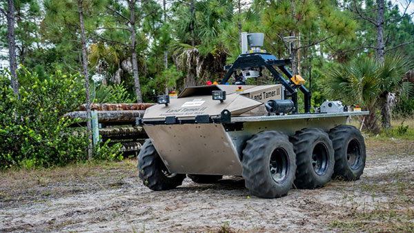
An unmanned Black Hawk delivers an autonomous ground vehicle to a remote site in a demonstration for the U.S. Army of a joint robotic air-ground mission.
Carnegie Mellon University and Sikorsky Aircraft used an autonomous helicopter and an autonomous ground vehicle to demonstrate that ground and air robots can perform complex, cooperative missions. In an October 2015 demo, an unmanned Black Hawk helicopter picked up an unmanned ground vehicle (UGV), flew a 12-mile route, delivered the UGV to a ground location and released it.
The drop-zone collaboration promises to keep warfighters out of harm’s way. For example, this type of robotic mission could avoid warfighters’ exposure to hazardous conditions, such as chemically or radiologically contaminated areas.
The Black Hawk was equipped for autonomous operation by Sikorsky, a Lockheed Martin Co. It delivered a Land Tamer autonomous unmanned ground vehicle from Carnegie Mellon’s National Robotics Engineering Center to a remote site, where the vehicle performed environmental monitoring for potential contamination.
“We were able to demonstrate a new technological capability that combines the strengths of air and ground vehicles,” said Jeremy Searock, NREC technical project manager. “The helicopter provides long-range capability and access to remote areas, while the ground vehicle has long endurance and high-precision sensing.”
Once the helicopter lowered the vehicle to the ground, the Land Tamer drove itself off its transport platform to commence its leg of the mission. The vehicle, equipped with sensors for detecting chemical, biological, radiological or nuclear contamination, then found and surveyed several potentially contaminated sites, autonomously traversing six miles in the process. When the vehicle sensors detected potential contamination, operators were able to switch the vehicle from autonomous operation into a tele-operated mode for a more detailed exploration of the site.
A JPADs pallet lands on target, followed by several others still in the air, during recent testing. (Photo: US Army)
The U.S. Army’s Joint Precision Airdrop System (JPADS) has developed a new capability with a navigation alternative to GPS. In recent tests, JPADS were dropped from planes, and immediately determined their location using optical sensors to compare local terrain with commercial satellite imagery. The new system demonstrated navigation to its intended point, using nothing but imagery to guide it.
JPADS, largely guided by GPS, has already proven its importance in supplying troops with necessary materials and equipment, relying less on vulnerable convoys. However, the new JPADS also works with little knowledge of the aircraft’s location at the drop point.
Dropping critical supplies from the air has allowed the U.S. military to rely less on easily-ambushed truck convoys and helicopter resupply. Exposure to improvised explosive devices (IEDs) and ambushed convoys resulted in more than 3,000 causalities in Afghanistan and Iraq through 2007.
JPADS has proven to be an important tool in the Army’s logistics chain in many scenarios to supply troops with material and equipment in adverse terrain and remote locations when ground lines of communication are not possible or deemed too high a risk.
“This is a huge step forward for aerial resupply,” said Chris Bessette, Draper’s JPADS program manager. “By enabling the system to operate using imagery alone when dropped as high as 25,000 feet above Mean Sea Level and upwards of 20 miles away from the target depending on winds, we can ensure that JPADS is even more versatile so troops receive supplies like fuel, ammunition, food, and water in the safest manner possible.”
In August, U.S. Army Gray Eagle unmanned aircraft took part in manned-unmanned teaming exercises in South Korea, including streaming video and metadata to an AH-64 Apache helicopter while in flight. The MQ-1C Gray Eagle proved its ability to conduct operations in diverse weather condition, according to manufacturer General Atomics Aeronautical Systems (GA-ASI). The Gray Eagle is used by the Army for reconnaissance, surveillance, communications, convoy protection, IED detection and precision weapons delivery.
During the exercise, the Gray Eagle UAS streamed video and metadata via a line-of-sight data link directly to the helicopter from extended distances. The Apache then retransmitted the imagery to a One System Remote Video Terminal (OSRVT), allowing field commanders within the Tactical Operations Center (TOC) to receive both live Gray Eagle streaming video and retransmitted video sent by the Apache. Once the Gray Eagle was airborne, U.S. ground forces passed contact reports and target coordinates to operators in the aircraft’s ground control station. The operators were then able to direct the Gray Eagle’s sensors to positively identify and track the targets.
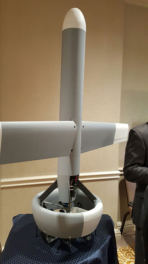
A V-Bat UAV from Martin UAV. Applications include aerial mapping, border patrol, shipboard operations and others.
Worldwide threats will make robotic and autonomous systems’ development important for decades, according to officials speaking at the Unmanned Systems Defense conference late last year.
GPS World’s contributing editor Kevin Dennehy wrote, “Because America has been at war for more than 14 years, unmanned technology has been developing at a rapid rate, perhaps even faster than emerging autonomous commercial systems. The replacement of even manned aircraft has some in the military establishment wary, but others know it’s only a matter of time before most vehicles, surface ships and aircraft are unmanned.”
The Secretary of the Navy said its current manned fighter plane, scheduled to see activity from now until 2037, may be its last to carry an actual human pilot.
The Navy’s Kraken drone munitions delivery system begins its mission underwater,then explodes past the surface to operate in the air. The Air Force also is developing small drones that can be launched and recovered by a larger aircraft after a mission is complete.
An Army initiative called Leader Follower includes rudimentary autonomous convoy operations capability with GPS and base mapping systems, autonomous steering and braking. Army program managers say the program is in staffing, but should be approved in a few months. A full-blown Automated Convoy Operations capability would allow any manned system, including tanks and mobile artillery, to operate autonomously. Last year, the Army and Lockheed Martin successfully demonstrated a driverless line-haul convoy with seven military trucks at speeds up to 40 mph.
Talking about a new generation
Lt. Gen. Michael Williamson, U.S. Army deputy to the assistant secretary of defense for acquisition, said the service is divesting its aging robotics and drone systems, which means future contracts for defense companies. “In 14 years of war, we have rode this equipment pretty hard,” he said. “We believe in modernization, but also looking to buy new systems, which is a new shift in order to gain a competitive advantage over our enemies, who are leveraging unmanned systems.”
The Defense Department recently established the Defense Innovation Unit, based in the San Francisco Bay area, to take advantage of rapid autonomous developments in the Silicon Valley.
Virtually all unmanned systems, from drones to autonomous vehicles, use GPS location technology and advanced mapping. As systems evolve, and enemy threats become more sophisticated, new requirements are emerging.
A surrogate LDUUV is submerged in preparation for a test to demonstrate the capability of the Navy’s Common Control System at the Naval Undersea Warfare Center Keyport in Puget Sound, Washington. (U.S. Navy photo)
In December 2015, the U.S. Navy tested its newly developed Common Control System (CCS) with a submersible unmanned vehicle in underwater missions in Puget Sound, Washington. The CCS successfully demonstrated its capability to provide command and control to a surrogate Large Displacement Unmanned Undersea Vehicle (LDUUV) — an underwater UAV destined for reconnaissance and surveillance missions.
CCS is a software architecture with a common framework, user interface and components that can be integrated on a variety of unmanned systems. It will provide common vehicle management, mission planning and mission management capabilities for the Naval unmanned systems portfolio. Operators used the CCS to transmit pre-planned missions via radio link to the LDUUV’s autonomous controller. In turn, CCS displayed actual vehicle status information to the operators. The vehicle was able to maneuver to the target areas and collect imagery.
“These tests proved that operators could use CCS from a single global operations center to plan, command and monitor UUVs on missions located anywhere in the world,” said Capt. Ralph Lee, who oversees the Navy’s CCS program at Patuxent River, Maryland. “This event also showed us that CCS is adaptable from the UAV (unmanned aerial vehicle) to UUV missions.”
CCS is intended to be compatible across all domains — air, surface, undersea and ground. The Navy initially plans to deploy the CCS on unmanned air vehicles. It will provide common vehicle management, mission planning and mission management capabilities for the Naval unmanned systems portfolio.
Exploiting terrestrial signals of opportunity (SOPs) can significantly reduce the vertical dilution of precision (VDOP) of a GNSS navigation solution. Simulation and experimental results show that adding cellular SOP observables is more effective in reducing VDOP than adding GNSS space vehicle (SV) observables.
By Joshua J. Morales, Joe J. Khalife and Zaher M. Kassas
GNSS position solutions can in many cases suffer from a high vertical dilution of precision (VDOP) due to lack of space vehicle (SV) angle diversity. Signals of opportunity (SOPs) have been recently considered to enable navigation whenever GNSS signals become inaccessible or untrustworthy. Terrestrial SOPs are abundant and are available at varying geometric configurations, making them an attractive supplement to GNSS for reducing VDOP.
Common metrics used to assess the quality of the spatial geometry of GNSS SVs are the parameters of the geometric dilution of precision (GDOP); namely, horizontal dilution of precision (HDOP), time dilution of precision (TDOP), and VDOP. Several methods have been investigated for selecting the best GNSS SV configuration to improve the navigation solution by minimizing the GDOP. While the navigation solution is always improved by additional observables from GNSS SVs, the solution’s VDOP generally remains of lesser quality than the HDOP. GPS augmentation with terrestrial transmitters that transmit GPS-like signals have been shown to reduce VDOP. However, this requires installation of additional proprietary infrastructure.
This article studies VDOP reduction by exploiting terrestrial SOPs, particularly cellular code division multiple access (CDMA) signals, which have inherently low elevation angles and are free to use.
In GNSS-based navigation, the states of the SVs are readily available. For SOPs, however, even though the position states may be known a priori, the clock-error states are dynamic; hence, they must be continuously estimated. The states of SOPs can be made available through one or more receivers in the navigating receiver’s vicinity. Here, the estimates of such SOPs are exploited and the VDOP reduction is evaluated.
PROBLEM FORMULATION
Consider an environment comprising a receiver, M GNSS SVs, and N terrestrial SOPs. Each SOP will be assumed to emanate from a spatially stationary transmitter, and its state vector, xsop(n), will consist of its three-dimensional (3-D) position rsop(n) and clock bias cδtsop(n), where n=1,…,N and c is the speed of light. The receiver draws pseudorange observations from the GNSS SVs and from the SOPs. The observations are fused through an estimator whose role is to estimate the state vector of the receiver xr=[rrT, cδtr] T, where rr and cδtr are the 3D position and clock bias of the receiver, respectively. To simplify the discussion, assume that the pseudorange observation noise is independent and identically distributed across all channels with variance σ2. The estimator produces an estimate of the receiver’s state vector and associated estimation error covariance P =σ2(HTH)-1.
Without loss of generality, assume an East-North-Up (ENU) coordinate frame to be centered at . In this frame, the dilution of precision matrix G≡(HTH)-1 is completely determined by the azimuth and elevation angles from the receiver to each SV, denoted azsv(m) and elsv(m), respectively, and the receiver to each SOP, denoted azsop(n) and elsop(n), respectively, where m=1,…,M. Hence, the quality of the estimate depends on these angles and the pseudorange observation noise variance σ2. The diagonal elements of G, denoted gii, are the parameters of the dilution of precision (DOP) factors:
Therefore, the DOP values are directly related to the estimation error covariance; hence, the more favorable the azimuth and elevation angles, the lower the DOP values. If the observation noise was not independent and identically distributed, the weighted DOP factors must be used.
VDOP REDUCTION VIA SOPs
With the exception of GNSS receivers mounted on high-flying and space vehicles, all GNSS SVs are typically above the receiver, that is, the receiver-to-SV elevation angles are theoretically limited between 0°≤elsv(m)≤90°. GNSS receivers typically restrict the lowest elevation angle to some elevation mask, elsv,min, so to ignore GNSS SV signals that are heavily degraded due to the ionosphere, troposphere and multipath.
As a consequence, GNSS SV observables lack elevation angle diversity, and the VDOP of a GNSS-based navigation solution is degraded. For ground vehicles, elsv,min is typically between 5° and 20°. These elevation angle masks also apply to low-flying aircraft, such as small unmanned aerial vehicles (UAVs), whose flight altitudes are limited to 500 feet (approximately 152 meters) by the Federal Aviation Administration (FAA).
In GNSS + SOP-based navigation, the elevation angle span may effectively double, specifically –90°≤elsop(n)≤90°. For ground vehicles, useful observations can be made on terrestrial SOPs that reside at elevation angles of elsop(n)=0°. For aerial vehicles, terrestrial SOPs can reside at elevation angles as low as elsop(n)=–90°, for example, if the vehicle is flying directly above the SOP transmitter.
To illustrate the VDOP reduction by incorporating additional GNSS SV observations versus additional SOP observations, an additional observation at elnew is introduced, and the resulting VDOP(elnew) is evaluated. To this end, M SV azimuth and elevation angles were computed using GPS ephemeris files accessed from the Yucaipa, California, station from Garner GPS Archive, which are tabulated in Table 1.
Table 1. SV azimuth and elevation angle (degrees).
For each set of GPS SVs, the azimuth angle of an additional observation was chosen as a random sample from a uniform distribution between 0° and 360°, that is, aznew~U(0°,360°). The corresponding VDOP for introducing an additional measurement at a sweeping elevation angle –90°≤elnew≤90° are plotted in Figure 1 (a)–(d) for M=4,…,7, respectively.
Figure 1. A receiver has access to M GPS SVs from Table 1. Plots (a)- (d) show the VDOP for each GPS SV configuration before adding an additional measurement (red dotted line) and the resulting VDOP(elnew) for adding an additional measurement (blue curve) at an elevation angle –90°≤elnew≤90° for M=4,…,7, respectively.
The following can be concluded from these plots. First, while the VDOP is always improved by introducing an additional measurement, the improvement of adding an SOP measurement is much more significant than adding an additional GPS SV measurement. Second, for elevation angles inherent only to terrestrial SOPs, that is, –90°≤elsop(n)≤0°, the VDOP is monotonically decreasing for decreasing elevation angles.
SIMULATION RESULTS
To compare the VDOP of a GNSS-only navigation solution with a GNSS + SOP navigation solution, simulations were conducted using receivers mounted on ground and aerial vehicles.
Ground Receiver. The position of a receiver mounted on a ground vehicle was set to rr ≡(106 )•[– 2.431171,– 4.696750, 3.553778]T expressed in an Earth-Centered-Earth-Fixed (ECEF) coordinate frame. The elevation and azimuth angles of the GPS SV constellation above the receiver over a 24-hour period was computed using GPS SV ephemeris files from the Garner GPS Archive. The elevation mask was set to elsv,min≡20°. The azimuth and elevation angles of three SOPs, which were calculated from surveyed terrestrial cellular CDMA tower positions in the navigating receiver’s vicinity, were set to azsop≡[42.4°,113.4°,230.3° ]T and elsop ≡[3.53°,1.98°,0.95°]T, respectively. The resulting VDOP, HDOP, GDOP and associated number of available GPS SVs for a 24-hour period starting from midnight, Sept. 1, 2015, are plotted in Figure 2.
Figure 2. Fig. (a) represents the number of SVs with an elevation angle >20° as a function of time. Fig. (b)-(d) correspond to the resulting VDOP, HDOP, and GDOP, respectively, of the navigation solution using GPS only, GPS + 1 SOP, GPS + 2 SOPs, and GPS + 3 SOPs.
The following can be concluded from these plots. First, the resulting VDOP using GPS + N SOPs for N≥1 is always less than the resulting VDOP using GPS alone. Second, using GPS + N SOPs for N≥1 prevents large spikes in VDOP when the number of GPS SVs drops. Third, using GPS + N SOPs for N≥1 also reduces both HDOP and GDOP.
Unmanned Aerial Vehicle. The initial position of a receiver mounted on a UAV was set to rr ≡(106 )•[–2.504728, –4.65991, 3.551203]T. The receiver’s true trajectory evolved according to velocity random walk dynamics. Pseudorange observations on all available GPS SVs above an elevation mask set to elsv,min≡20° and three terrestrial SOPs were generated using a MATLAB-based simulator. The simulator used SV trajectories which were computed using GPS SV ephemeris files from Sept. 1, 2015, 10:00 to 10:03 a.m.
The positions of the SOPs were set to rsop(1)≡(106)•[– 2.504953,– 4.659550, 3.551292]T, rsop(2)≡(106)•[– 2.503655, –4.659645, 3.552050]T, and rsop(3)≡(106)•[– 2.504124,– 4.660430, 3.550646]T, which are the locations of surveyed cellular towers in the UAV’s vicinity. The UAV’s true trajectory, navigation solution from using only GPS SV pseudoranges, and navigation solution from using GPS and SOP pseudoranges are illustrated in Figure 3 (top). The corresponding 95th-percentile uncertainty ellipsoids for a sample set of navigation solutions are illustrated in Figure 3 (bottom).
Figure 3 . Simulation results for a UAV flying over downtown Los Angeles. Top: Illustration of the true trajectory (red curve), navigation solution from using pseudoranges from six GPS SVs (yellow curve), and navigation solution from using pseudoranges from six GPS SVs and three cellular CDMA SOPs (blue curve). Bottom: Illustration of uncertainty ellipsoid (yellow) of GPS only navigation solution and uncertainty ellipsoid (blue) of GPS + SOP navigation solution.
The following can be noted from these plots. First, the accuracy of the vertical component of the GPS-only navigation solution is worse than that of the GPS + SOP navigation solution. Second, the uncertainty in the vertical component of the GPS-only navigation solution is larger than that of the GPS + SOP navigation solution, which is captured by the yellow and blue uncertainty ellipsoids, respectively. Third, the accuracy of the horizontal component of the navigation solution is also improved by incorporating cellular SOP pseudorange observations alongside GPS SV pseudorange observations.
EXPERIMENTAL RESULTS
A field experiment was conducted using software-defined receivers (SDRs) to demonstrate the reduction of VDOP obtained from including SOP pseudoranges alongside GPS pseudoranges for estimating the states of a receiver. To this end, two antennas were mounted on a vehicle to acquire and track multiple GPS signals and three cellular base transceiver stations (BTSs) whose signals were modulated through CDMA. The GPS and cellular signals were simultaneously downmixed and synchronously sampled via two universal software radio peripherals (USRPs). These front-ends fed their data to the Multichannel Adaptive TRansceiver Information eXtractor (MATRIX) SDR, developed at the Autonomous Systems Perception, Intelligence and Navigation (ASPIN) Laboratory at the University of California, Riverside. The LabVIEW-based MATRIX SDR produced pseudorange observables from five GPS L1 C/A signals in view and the three cellular BTSs.
Figure 4 depicts the experimental hardware setup.
Figure 4. Experiment hardware setup.
The pseudoranges were drawn from a receiver located at rr≡(106)•[– 2.430701,– 4.697498, 3.553099]T, expressed in an ECEF frame, which was surveyed using a carrier-phase differential GPS receiver. The corresponding SOP state estimates were collaboratively estimated by receivers in the navigating receiver’s vicinity. The pseudoranges and SOP estimates were fed to a least-squares estimator, producing x^r and associated P from which the VDOP, HDOP, and GDOP were calculated and tabulated in Table 2 for M GPS SVs and N cellular CDMA SOPs. A sky plot of the GPS SVs used is shown in Figure 5.
Figure 5. Left: Sky plot of GPS SVs: 14, 21, 22, and 27 used for the four SV scenarios. Right: Sky plot of GPS SVs: 14, 18, 21, 22, and 27 used for the five SV scenarios. The elevation mask, elsv,min, was set to 20° (dashed circle).
The tower locations, receiver location and a comparison of the resulting 95th-percentile estimation uncertainty ellipsoids of for {M,N}={5,0} and {5,3} are illustrated in Figure 6.
Figure 6. Top: Cellular CDMA SOP tower locations and receiver location. Bottom: Uncertainty ellipsoid (yellow) of navigation solution from using pseudoranges from five GPS SVs and uncertainty ellipsoid (blue) of navigation solution from using pseudoranges from five GPS SVs and three cellular CDMA SOPs.
The corresponding vertical error was 1.82 meters and 0.65 meters respectively. Hence, adding three SOPs to the navigation solution that used five GPS SVs reduced the vertical error by 64.3 percent. Although this is a significant improvement over using GPS observables alone, improvements for aerial vehicles are expected to be even more significant, since they can exploit a full span of observable elevation angles as demonstrated in the simulation section.
Table 2. DOP values for M SVs + N SOPs.
CONCLUSION
This article studied the VDOP reduction of a GNSS-based navigation solution by exploiting terrestrial SOPs. It was demonstrated that the VDOP of a GNSS solution can be reduced by exploiting the inherently small elevation angles of terrestrial SOPs. Experimental results using ground vehicles equipped with SDRs demonstrated VDOP reduction of a GNSS navigation solution by exploiting a varying number of cellular CDMA SOPs. Incorporating terrestrial SOP observables alongside GNSS SV observables for VDOP reduction is particularly attractive for aerial systems, since a full span of observable elevation angles becomes available.
MANUFACTURERS
Two National Instruments universal software radio peripherals were used in the experiment. A Trimble 5700 receiver surveyed the experimental receiver location.
JOSHUA J. MORALES is pursuing a Ph.D. in electrical and computer engineering at the University of California, Riverside.
JOE J. KHALIFEH is a Ph.D. student at the University of California, Riverside.
ZAHER (ZAK) M. KASSAS is an assistant professor at the University of California, Riverside. He received a Ph.D. in electrical and computer engineering from the University of Texas at Austin. Previously, he was a research and development engineer with the LabVIEW Control Design and Dynamical Systems Simulation Group at National Instruments Corp.
This article is based on a technical paper presented at the 2016 ION ITM conference in Monterey, California.
A methane leak at a Southern California Gas (SoCalGas) storage facility has shone a spotlight on how unmanned aerial vehicles can be used to inspect utilities. The massive three-month leak — temporarily plugged on Feb. 12 — chased thousands of Los Angeles residents from their homes.
At least 2 percent of natural gas is wasted through methane leaks at production sites, according to the U.S. Department of Energy (DOE).
UAVs are already being used for some electrical grid and pipeline inspections, mostly in pilot programs, but their potential for hands-off long-distance monitoring is just starting to be realized.
Along with criminal charges, SoCalGas is facing regulatory mandates to improve air-quality monitoring at its facilities. Nationally, the DOE’s Advanced Research Project Agency-Energy is funding a program to accurately locate and measure methane emissions associated with natural gas production.
Bridger’s proposed leak detector uses lidar in combination with range and gas absorption measurements. (Illustration: Bridger Photonics)
The program has given one company, Bridger Photonics, a $2 million grant to develop a leak detector. Bridger plans to build a mobile methane sensing system capable of surveying a 10 x 10 meter well platform in just over five minutes with precision that exceeds existing technologies used for large-scale monitoring.
Bridger’s detector useslaser beams to generate 3D images that show the distance and concentration of a gas leak, even showing the types and concentration of the hydrocarbons.
Mounted on a UAV, the sensor would give inspectors access to complicated or obscured infrastructures at processing plants, drilling rigs and pipelines. The sensor could also be mounted on a vehicle.
Bridger’s goal is for its devices to be able to service up to 85 sites, and cost $1,400 to $2,220 a year to operate per wellsite. Bridger plans to field test its technology this year and make it available commercially in 2017.
Bridger’s imager
Bridger’s gas imager is a point-scanning lidar sensor that performs simultaneous range and gas absorption measurements, according to Mike Thorpe, chief technology officer of Bridger Photonics. The measurements are combined to derive high-accuracy estimates of the gas concentration.
The measurement beam is scanned around the scene to create 3D topographic images of hard targets overlaid with 2D maps of the gas concentration.
The datasets will be geo-registered using GPS and inertial measurements.
The prototype sensor will have the following performance specs:
1 kpps measurement rate
3-100 m range
1 cm down-range resolution
2 cm cross-range resolution
<3 ppm-m methane detection sensitivity for distances < 30 m
<15 ppm-m methane detection sensitivity for distances < 100 m
Bridger also is developing measurement approaches and algorithms to enable automatic leak detection and leak rate estimation.
Unmanned aerial vehicle maker DJI has launched the Phantom 4, a quadcopter drone that uses highly advanced computer vision and sensing technology to make professional aerial imaging easier.
The Phantom 4 expands on previous generations of DJI’s Phantom line by adding on-board intelligence that make piloting and shooting great shots easier through features such as its Obstacle Sensing System, ActiveTrack and TapFly functionality.
“With the Phantom 4, we are entering an era where even beginners can fly with confidence,” said DJI CEO Frank Wang. “People have dreamed about one day having a drone collaborate creatively with them. That day has arrived.”
The Phantom 4’s Obstacle Sensing System features two forward-facing optical sensors that scan for obstacles and automatically direct the aircraft around impediments when possible, reducing risk of collision, while ensuring flight direction remains constant.
If the system determines the craft cannot go around the obstacle, it will slow to a stop and hover until the user redirects it. Obstacle avoidance also engages if the user triggers the drone’s “Return to Home” function to reduce the risk of collision when automatically flying back to its take off point.
With ActiveTrack, the Phantom 4 allows users running the DJI Go app on iOS and Android devices to follow and keep the camera centered on the subject as it moves by tapping the subject on their smartphone or tablet. Perfectly framed shots of moving joggers or cyclists, for example, only require activating the ActiveTrack mode in the app.
The Phantom 4 understands three-dimensional images and uses machine learning to keep the object in the shot, even when the subject changes its shape or turns while moving. Users have full control over camera movement while in ActiveTrack mode — and can move the camera around the object while it is in motion as the Phantom 4 keeps the subject framed in the center of the shot autonomously. A “pause” button on the Phantom 4’s remote controller allows the user to halt an autonomous flight at any time, leaving the drone to hover.
By using the TapFly function in the DJI Go app, users can double-tap a destination for their Phantom 4 on the screen, and the Phantom 4 calculates an optimal flight route to reach the destination, while avoiding any obstructions in its path. Tap another spot and the Phantom 4 will smoothly transition towards that destination making even the beginner pilot look like a seasoned professional.
The Phantom 4’s camera, an aerial-optimized 4K imaging device, has undergone an upgrade that includes improved optics for better corner sharpness and reduced chromatic aberration. The Phantom 4 also has DJI’s signature Lightbridge video transmission system onboard, allowing users to see what their camera sees in HD and in real-time on their smart devices at a distance up to five kilometers (3.1 miles).
The Phantom 4’s form factor, the classic quadcopter, has been redesigned and redefined to emphasize elegance and smoother, more aerodynamic lines. Its frame incorporates a lightweight composite core to provide enhanced stability and more agile flight. The core features a redesigned gimbal that provides more stability and vibration dampening, and has been repositioned for a better center of gravity and to reduce the risk of propellers getting in the shot.
Refinements to motor efficiency, power management and a new intelligent battery have extended the Phantom 4’s flight time to 28 minutes, which means more time in the air to capture professional photos and video.
DJI crafted the Phantom 4 with reliability in mind, including redundant inertial measurement units (IMUs) and dual compasses onboard. It uses new push-and-lock propellers that are faster to install and more secure in flight.
In addition to intelligence and ease-of-use, the Phantom 4 is built for fun, DJI said. Its new “Sport Mode” for advanced flyers gives a taste of what drone racing feels like. In “Sport Mode,” the Phantom 4 can fly 20 meters per second (45 miles per hour) and ascends and descends more rapidly than in other modes. The craft’s acceleration and top speed in “Sport Mode” also mean it can reach locations for shots faster and capture shots users couldn’t get before.
“Though the Phantom 4 is easy to use, let’s not forget it is a high-performance aircraft powered by unparalleled DJI technology,” said Senior Product Manager Paul Pan.
Powervision Robot Inc., a robotics and industrial drone maker, has launched drone shaped like an egg that can be folded up and stored in a backpack.
Although PowerEgg was developed for the mainstream consumer market, it includes advanced technologies such as a 360-degree panoramic 4K HD camera on a 3-axis gimbal, real-time long-range video transmission and advanced “optical flow” sensors for indoor navigation.
Powervision CEO Wally Zheng called the design a “work of art.” “We think the oval shape is not only clean and pure but also has the structural and functional benefits.”
The Powervision team spent more than 18 months to create the PowerEgg. The structural design includes larger propellers that required advancements to transform from the compact egg shape to the larger flight mode. On the software side, Powervision concentrated on making the drone easier to fly, because the average consumer drone has a 10-hour learning curve.
Since its inception in 2010, Powervision has focused on commercial UAV-related products and services including smart drones, data visualization and forecasting.
PowerEgg will be available early in the second quarter of this year.
The U.S. Federal Aviation Administration (FAA) is establishing an aviation rulemaking committee with industry stakeholders to develop recommendations for a regulatory framework that would allow certain UAS to be operated over people who are not directly involved in the operation of the aircraft.
The FAA is taking this action to provide a more flexible, performance-based approach for these operations than what was considered for micro UAS. A UAS is generally defined as a micro UAS if it weighs no more than 4.4 pounds (2 kilograms) and is constructed of frangible materials “that break, distort, or yield on impact so as to present a minimal hazard to any person or object.”
The committee will begin its work in March and issue its final report to the FAA on April 1. The Association for Unmanned Vehicle Systems International (AUVSI) is a participant.
“The Department continues to be bullish on new technology,” said U.S. Transportation Secretary Anthony Foxx. “We recognize the significant industry interest in expanding commercial access to the National Airspace System. The short deadline reinforces our commitment to a flexible regulatory approach that can accommodate innovation while maintaining today’s high levels of safety.”
The rulemaking committee will develop recommendations for performance-based standards for the classification and operation of certain UAS that can be operated safely over people; identify how UAS manufacturers can comply with the requirements; and propose operational provisions based on the requirements. The FAA will draft a rulemaking proposal after reviewing the committee’s report.
“Based on the comments about a ‘micro’ classification submitted as part of the small UAS proposed rule, the FAA will pursue a flexible, performance-based regulatory framework that addresses potential hazards instead of a classification defined primarily by weight and speed,”said FAA Administrator Michael Huerta.
To develop this framework, the FAA is seeking advice and recommendations from a diverse set of aviation stakeholders, including UAS manufacturers, UAS operators, consensus-standards organization, and researchers and academics.
The UAS registration task force established last October serves as a model for the Micro UAS rulemaking committee. The committee will be co-chaired by Earl Lawrence, Director, FAA UAS Integration Office and Nancy Egan, General Counsel, 3D Robotics.
This month’s column recaps UAV news that you may or may not have picked up over the last few weeks. We start with stories related to the rules for operating drones in the U.S., then we’ll look at bird-like drones — used to scare away birds, new commercial UAV applications, and steps being taken to protect us from malicious use of drones and other possible “impacts” of drones.
Who owns the air?
A long time back, the U.S. Congress passed laws which gave the government control above 500 feet and limited land rights so that overflying aircraft could not be considered as trespassing over private property. But, it turns out, ownership of the airspace from the ground up to 500 feet may not be that clear.
The Federal Aviation Administration (FAA) recently reaffirmed that the agency controls all U.S. airspace, even right down to the ground, but it seems that landowners may still have some claim to their own air directly above their property.
In a precedent-setting case dating back to World War II, the U.S. Supreme Court said that landowners have rights to as much airspace as they can use for the enjoyment and use of their land. So if “enjoyment and use” entails flying a UAV at up to 500 feet above their property or alternatively requires no UAVs flying above their own roof-line, who’s rights prevail?
Certainly, there seems to be a number of people who are not too fond of UAVs being allowed to fly over their homes at low altitude. Manned aircraft might be a different kettle of fish as they generally fly higher and don’t seem to bug most people as much. And noise abatement regulations attempt to limit the sound of loud aircraft engines on landing and take-off.
But with this continuing ambiguity, several state and local governments have already begun to take steps to protect airspace over people’s homes.
There are currently more than 150 active bills in more than 30 states — either carried over from 2015 or introduced this year.
Indeed, the FAA, in an effort to dissuade such lawmaking activity, recently released a fact sheet on state and local drone regulations: “Navigable airspace free from inconsistent state and local restrictions is essential to the maintenance of a safe-and-sound air transportation system,” said the FAA. The agency urged local and state lawmakers to consult it before making any new regulations. And it would clearly be far better for drone manufacturers and operators if there was only one set of (FAA) regulations across the whole U.S., rather than each user having to navigate a tangled web of potentially conflicting local and state regulations.
In the meantime, there has been at least one case in which a property owner sought to protect his “home and castle” by unloading a shotgun into a low-overflying drone. The lawsuit was settled to the benefit of the property owner, rather than the drone operator, so property rights did prevail in this case.
Nearly 300,000 owners have registered their small unmanned aircraft (sUAV) in the first 30 days using the FAA’s online registration system and have received a refund for the $5 application fee. While the refund period has now expired, the agency continues to see a steady stream of daily registrations.
The FAA’s registration rule, which took effect on December 21, 2015, applies to sUAV that weigh between 0.55 lbs. and 55 lbs. Existing owners of these aircraft must register before Feb. 19, 2016. The current online system only supports use by recreational or hobby operators, while the FAA hopes to provide commercial operators with access by March 21.
Name, address and email are required ,and a registration number and printable certificate are then provided. The registration number must be marked on the UAV.
A drone flies in Russia.
Meanwhile, Russian President Vladimir Putin has signed a law that obliges all private owners of unmanned aircraft weighing more than 250 grams to register them with the Federal Air Transport Agency.
According to the new act, which comes into force at the end of March 2016, owners and operators of unmanned aircraft systems (UAS) must also appoint a crew and a commander responsible for flight safety. In order to operate, a flight plan must be submitted to the regional air traffic controllers — as required for manned aircraft operations — and the flight plan has to be followed unless an emergency landing is necessary when there is a threat to public safety.
Is that a bird or a drone?
But, of course, the more we try to overcome issues related to UAVs, the more complicated it seems to become. A core element of all FAA authorizations to date has been that a drone should never be operated within several miles of an airport to avoid collisions with aircraft. Now, a company has come up with a drone which carries a broadcast sound unit, programmed with a number of hawk, owl and other bird calls — ideal for scaring feeding or roosting birds away from areas we want to clear, such as at airport runways.
Bird strikes by aircraft in the critical phases of landing or take-off are a major concern for airlines and airports alike. Many methods have been tried to reduce birds flying around at the sound of loud aircraft noise. Birds can get sucked into engines or can damage other critical aircraft structures. Air blasts that sound like shotguns and flying live falcons are only a couple of methods used to clear birds away from airport approaches, departures and runways.
Bird-repelling drone.
In the meantime, at least one enterprising associate prof at the University of Illinois has recognized the requirement and is developing a robotic falcon that chases birds away from airfields.
A flying falcon.
Soon-Jo Chung and his team have been supported by funding not only by the National Science Foundation’s CAREER Award program to create the flying falcon above, but also by other sources to develop vision-based navigation. An analytical computer simulation has replicated motion control and avoidance so the robotic falcon can intelligently come up with motion planning algorithms.
And another the twist to this story is that bald eagles and other birds of prey are being trained to hunt and take down drones in the Netherlands. Dutch police have been investigating this natural “anti-drone technology” to combat criminal use of drones, and to counter the prospect of drones being used to deliver bombs or chemical and biological weapons.
UAV inspection/monitoring to reduce costs and enhance safety
A DJI UAV was recently used by Lufthansa Aerial Services to inspect rotor blades on wind turbines. Previously, inspection was somewhat dangerous, and required climbing the wind turbine tower. While cost reduction may be the principle motivation, it’s possible that wind turbine inspection and maintenance periods could also be extended.
And, in partnership with Flot Systems, Xcel Energy has become the first utility company to use drones in beyond-line-of-sight inspection of more than 320,000 miles of electricity and natural gas infrastructure.
Xcel began using UAVs to visually inspect substations in 2015, and is one of the first operations to receive FAA approval for research to use “beyond visual line of sight” for these inspections.
Previously, manned helicopters were contracted that would carry an inspector and would fly along transmission lines. But from a safety viewpoint, flying UAVs near high-voltage lines is less risky for workers and pilots. Transmission line inspectors also used to have to walk through difficult terrain which can also be hazardous.
(Editor’s note: Look for more information on UAV’s used for utility inspections in the March issue of GPS World.)
Another major area that can benefit from the use of drones is agriculture. Remote crop inspection through live and recorded video helps farmers gather much better information to support improved crop growth.
A Hermes 450 may be gathering lots of usable growing crop information this summer, provided an ag project in North Dakota is approved. The UAV can carry up to 400 pounds of sensors and cameras, and collects data at around 92 mph for 14 hours at 8,000 feet, covering 50,000 acres per hour.
Photos and videos of growing corn, sugar beet and other crops have the potential to identify fertility deficiencies, yield estimates, and weed and disease issues. North Dakota State University (NDSU) is collaborating with the Northern Plains UAS Test Site and Elbit Systems of America to conduct the crop project.
The operation is planned to cover a whole county in North Dakota, mostly outside line-of-site of the operator, so in this case a manned aircraft is needed to observe the UAV — it’s a safety condition of the FAA Section 333 approval. Many producers in North Dakota are already buying, registering and flying their own smaller UAVs.
And one drone operator is taking a pro-active approach to help the agriculture industry decide if using drones can help them. Working with the American Farm Bureau Federation, on behalf of several major sponsors, Measure has released what it calls the Drone Flight Calculator.
The Drone Flight Calculator quantifies the economic benefits of using drone services for crop monitoring — such as soy, corn or grapes. When data such as fertilizer use, farm size, and crop type are entered, the calculator provides economic returns by acre and for each growing season. Farmers can also learn how much they can expect to save on inputs such as fertilizer and irrigation.
Drone flies into hurricane
The National Oceanic and Atmospheric Administration (NOAA) has been working with several UAVs to investigate the tracking and modeling of hurricanes. NOAA successfully deployed a Coyote UAV from a P-3 hurricane hunter aircraft into the eye of Hurricane Edouard in the fall of 2014. The Coyote is a small, expendable UAS that can be tube-launched from an aircraft or from the ground.
The seven-pound unmanned aircraft was deployed from a free-fall chute in the belly of the plane, which then opened its six-foot wingspan to fly through the storm. It can be controlled from miles away, but was piloted by scientists onboard the P-3.
A successful calibration flight over Avon Park, Florida, was recently completed, where a Coyote was launched from a P-3 hurricane hunter aircraft to prepare for deployment during storm season.
“This successful flight gives us additional confidence that we will be able to use this unique platform to collect critical continuous observations at altitudes in the storm environment that would otherwise be impossible,” said Joe Cione, a hurricane researcher at NOAA’s Atlantic Oceanographic and Meteorological Laboratory and chief scientist of the Coyote program.
With a particularly military look to it, a consortium of British companies has come up with a system to defeat potential attacks using drones. Dubbed the Anti-UAV Defence System (AUDS), it combines electronic scanning air security radar, a stabilized electro-optic director, infrared and daylight cameras, target tracking software, and a directional radio frequency (RF) inhibitor/jammer system.
Anti-UAV Defence System (AUDS).
The portable system can spot small, slow-moving drones up to four miles away using radar. A military-grade camera then tracks it before jamming the radio signals that control it, making it impossible to fly. The whole process can take as little as 15 seconds.
With incidents of drone-related security breaches occurring regularly, there is a need to address heightened UAV concerns within military, government, critical infrastructure and commercial security organizations. While UAVs have many more positive applications, it’s nevertheless anticipated that they could also be used for terrorism, espionage and smuggling — with cameras, weapons, toxic chemicals, explosives and drugs as potential payloads.
The AUDS technology has apparently been extensively tested in South Korea, at French government trials and in UK government-sponsored counter-UAV trials.
In fact, this system or one very much like it underwent a successful trial at London’s Remembrance Day parade. The system was installed on the roof of Scotland Yard, close to where the Nov. 11 ceremonies took place. Police in the UK are apparently looking for such a device to block drones flown by terrorists at major public and sports events.
Along the same lines, Drone Labs has developed a Drone Detector unit that appears to use audio and radio frequency sensors along with GPS to find not only a drone, but also the location of the operator, over at least a range of 1 kilometer.
Drone Labs plans to add video, thermal and radar detection capabilities. The object is to provide some level of protection from drones used for illegal activities, such as delivering contraband at prisons. Some operations already using the system include movie sets, celebrities and facility management professionals seeking to protect assets and people from intrusive drones, as well as law enforcement. Presumably, criminals might also use such a system to reduce the risk of detection by law enforcement drones.
Crashing drone nearly hits skier
And, while it’s good that we put attention on protecting us from potential drone attacks, it’s unfortunate that we recently witnessed live TV coverage of a drone crash that could have had really bad consequences. In December, one of world’s best Alpine skiers was lucky not to be taken out by a crashing drone carrying a TV camera during a slalom run in Italy. Unfortunately, following the incident, the International Ski Federation (IFS) went on to ban camera drones from its World Cup races.
IFS’s broadcast partner — Infront Sports and Media — has indicated the likelihood that the control link to the UAV may have been lost, possibly due to radio interference. Infront has decided to engage an external independent expert to formally investigate the incident. IFS noted that the drone operator had agreed to maintain a safe 15-meter distance from the ski slope. However, it’s possible this safety margin was not maintained…..err, well, it would seem so! The drone fell directly onto the ski slope!
So, maybe it was some over-zealous operator error along with a technical failure — this can happen with any technology — but hopefully no active jamming was involved. For one, I was happy that nothing broke on the overhead camera-carrying wire-system following the action on the field at the Super Bowl this weekend! (It wasn’t such an exciting game in the end anyway.…)
Almost every day, news about UAVs continues to pour in with updates on regulation, legal aspects of drone operations, new ways to reduce costs by applying drones to an existing task, and privacy and security angles on why and when something should or shouldn’t be done with an unmanned air vehicle. It’s interesting to watch how things develop in this new industry — almost like when GPS was brand-new and just getting started…
A team from the National Oceanic and Atmospheric Administration (NOAA) and Raytheon has successfully demonstrated advancements of the Coyote Unmanned Aircraft System (UAS), verifying new technology that improves Coyote’s ability to collect vital weather data on hurricanes.
Coyote drops out of a P-3 weather surveillance plane, spreads its wings and flies straight at a hurricane, braving violent winds and punishing rain to gather weather data and beam it back to meteorologists.
Drew Osbrink and Eric Redweik of Sensintel and NOAA hurricane researcher Joe Cione monitor data from the Coyote as it flies into Hurricane Edouard in 2014. (Photo: NOAA)
Coyote solves a problem that has limited forecasters’ ability to tell how hard a hurricane will hit. The secret behind the storm’s punch lies in what is known as the “boundary layer” — a low-altitude area that includes the surface of the ocean. Because hurricanes are fueled by warm ocean water, information collected at the interface of atmosphere and ocean is vital to the understanding and prediction of a storm’s strength.
“That’s where the energy is extracted from the ocean to the atmosphere,” said Joe Cione, a NOAA hurricane researcher. “Unfortunately, it is too difficult for us to go with manned aircraft to fly down there.”
The Coyote can maneuver in the most violent regions of a hurricane.Traditional weather instruments parachute from a plane and grab only a snapshot of humidity, wind speed and other factors, but Coyote’s winged design enables it to linger and return to certain areas for more measurements.
“Coyote will gather data specifically in the eye wall where it can provide information for forecasters to predict intensity from a safe distance,” said John Hobday, Raytheon. “This is a significant difference for researchers: instead of providing a snapshot of data, it’s a full-length movie.”
The Coyote after a successful flight on Jan. 7. (Photo: NOAA)
Operational Upgrades
In a Jan. 7 test, the Coyote was released from NOAA’s Hurricane Hunter P-3 aircraft and flew over the Avon Park Air Force Range in Florida, to measure the transmission range of upgraded technologies. It set a new distance record for flight control and data transmission to the P-3, and provided hurricane forecasters with real-time data on atmospheric air pressure, temperature, moisture, wind speed and direction as well as surface temperature.
Data collected will help improve the accuracy of forecasts. “Here at the National Hurricane Center (NHC), we are keenly interested in obtaining measurements from the Coyote of the strongest winds near the center of the storm,” said Chris Landsea, science operations officer at NHC. “Coyote could help us paint a better picture of current storm intensity for our storm updates.”
In 2014, NOAA deployed four of the Coyote planes into Hurricane Edouard, a Category 3 storm, at controlled altitudes as low as 400 feet. Scientists on board the P-3 received meteorological data in both the eye of the storm and the eye wall.
However, the P-3 had to fly 5 to 7 miles from the Coyote to pick up its signal. So engineers at Raytheon and the NOAA Aircraft Operations Center upgraded Coyote’s sensor systems and improved its communications package to allow it to talk to the plane over longer distances. Now, Coyote can fly for 50 miles away from the launch aircraft, which will be free to continue its own mission.
Coyote also was outfitted with an upgraded instrument package that includes an infrared sensor to measure sea surface temperature, which will help scientists understand how a hurricane extracts energy from the ocean — and how it might intensify or change. The team also is working toward optimizing battery life.
The test flight verified the Coyote’s ability to transmit the data collected from its instrument package to operators aboard the P-3 as well as at the NHC, where personnel monitor storms and develop forecasts.
NOAA scientist Paul Reasor demonstrates the Coyote. (Photo: NOAA)