Tag: warfighter

  • New military code about to board 700+ platforms

    New military code about to board 700+ platforms

    Rolling out Military Code

    Photo: U.S. Air Force / Staff Sgt. Scott H. Spitzer
    Photo: U.S. Air Force / Staff Sgt. Scott H. Spitzer

    Much development has been necessary to enable the new M-code capability on more than 700 weapon systems that require it. This article overviews M-code, the updates to antenna and receiver technology to make these varied platforms M-code ready, and perspectives from key stakeholders in the M-code community.

    December 23, 2018, marked an important milestone for GPS. The successful launch of satellite USA-289 represented a key success in what has been a monumentally expensive government program, beset by delays and overspends.

    The launch of the first GPS Block III satellite, the first that can provide the full military M-code capability, effectively commenced the physical roll-out of modern M-code hardware.

    Ground Control. As far as the space segment is concerned, M-code is finally underway. What about the ground segment? The next-generation GPS operational control system, GPS OCX, is essential for use of the full capabilities of the new Block III satellites. It has been under development for some time.

    OCX has drawn Congressional criticism and correlative media attention, but recent reports have been more positive. Since the Nunn-McCurdy breach of 2016, when the project’s future hung in the balance, accounts have grown gradually optimistic. Budget and schedule were re-baselined, and contractor Raytheon’s corrective actions generated results. In the fall of 2017 the Air Force took delivery of OCX Block 0, marking a significant milestone. Block 0, also known as the Launch and Checkout System (LCS), demonstrated compliance with contractual requirements and was accepted by the Air Force.

    In spring 2018, Block 0 underwent a series of cybersecurity tests and passed, validating the security architecture of the system. All this puts Raytheon on track to deliver OCX Block 1 in 2021, providing full operational capability. Block 1 and Block 2 are intended to be delivered together, adding operational control of the modernized satellites and signals, including L1C and the modernized M-code.

    “There have been no schedule slips with the GPS OCX program since 2017, and the GPS III launch last December was clear proof of our progress,” stated Dave Wajsgras, president of Raytheon’s Intelligence, Information and Services business. “We will continue to meet all of our commitments, and importantly, we will meet our June 2021 contractual deadline.”

    Col. Steve Whitney of the GPS Directorate wrote in this magazine in December 2018 that “The journey over the past few years has been challenging, but we have emerged stronger, armed with better metrics, and a culture of integrated development (often called DevOps) which puts us on a path to success. There will be challenges and risks in the path ahead but rather than mountains to climb, I see these more as standard blocking and tackling of a software-intensive program.”

    Meanwhile. The Air Force plans to deploy M-code capability in 2020, and OCX seems unlikely to be ready. For this reason, Lockheed Martin was awarded a contract to modernize the existing ground infrastructure as a “gap filler.”

    The GPS Control Segment Sustainment II (GCS II) contract was awarded on Dec. 21, 2018, and is worth $462 million. GCS II will support operational capability of M-code in 2020, and continues until 2025, and so there will be a period of overlap between GCS II and OCX, essentially providing two options for controlling the new GPS III constellation. In one view, the Air Force is backing two horses to improve chance of winning: OCX the preferred solution, with GCS II almost like an insurance policy.

    With the GPS III ground and space segments looking relatively healthy, attention turns again to the user segment.

    WHY M-CODE?

    Until now, the military has used the classic P(Y) signal: a binary phase shift keying (BPSK)-modulated encrypted wideband signal. It offers both greater accuracy and increased jamming resistance when compared to the civilian C/A code still employed by the vast majority of GPS receivers.

    But the P(Y) code has its drawbacks in the modern world: its wide main lobe sits directly over the top of the C/A code signal (see Figure 1), essentially occupying the same spectrum. When the civilian C/A signal is jammed, the military P(Y) signal is at the very least degraded, if not also jammed itself. It also uses a relatively simple encryption scheme that does not meet today’s cyber security requirements.

    Figure 1. C/A, P(Y), and M-Code signal power spectra. (Graphics: Mike Jones)
    Figure 1. C/A, P(Y), and M-Code signal power spectra. (Graphics: Mike Jones)

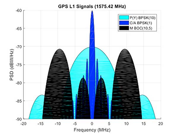
    The M-code signal, on the other hand, is the first military GPS signal to use the BOC modulation scheme. BOC modulation gives signals their distinctive two-lobe appearance, spreading the signal’s energy away from the band center.

    The wide spacing of the two sidebands separates the M-code signal from the civilian signals (the legacy C/A signal or the new L1C signal on the L1 frequency, and the L2C signal on the L2 frequency).

    Amongst other things, this allows the military to jam the civilian codes without noticeably degrading the M-code signal. Often referred to as blue force electronic attack (BFEA), this is essentially a new facet to navigation warfare (NAVWAR), where enemy use of GPS can be denied whilst allowing friendly forces to continue using it.

    The wider occupied bandwidth and increased signal power also help to make M-code more resistant to jamming. M-code also makes use of more modern and flexible encryption methods, ensuring it will be secure and safer from threats such as spoofing attacks.

    Scepticism. Defense programs are known for their long procurement cycles, but even by these standards, M-code has taken an extremely long time to get where it is today. Given the enormous cost of the program, and the fact that there is still, as yet, no operational benefit to show from it, many people have questioned its worth. At the time it was conceived it represented a dramatic step forward in military capability but, because it has been so long in development, its operational benefit is becoming diluted.

    When M-code was conceived, GPS was still the only operational GNSS in town: everybody had to use GPS — or nothing. Today, the picture differs greatly. During M-code’s insanely slow progress, other GNSS systems have come along, offering their own encrypted signals of a similar ilk. Looking at Figure 2, M-code no longer appears as special as it once was. Its BOC(10,5) signal sits inside the main lobes of Europe’s Galileo PRS signal, which uses a BOC(15,2.5) scheme, and China’s Beidou B1A signal using BOC(14,2).

    Figure 2. GNSS encrypted signals around the L1 frequency. (Graphics: Mike Jones)
    Figure 2. GNSS encrypted signals around the L1 frequency. (Graphics: Mike Jones)

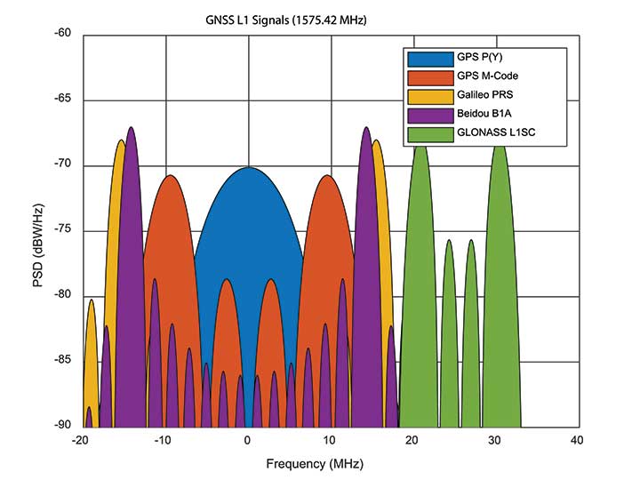
    If you were China, you might consider jamming the central 24 MHz of the L1 band, taking out M-code, whilst still having an operational military service for yourself. Or if you were Russia, you might jam 34 MHz of bandwidth, taking out the US, Chinese, and European systems, whilst still having your GLONASS L1SC military service to use. The situation is more complex than that, of course: each service has the potential to increase signal power in times of conflict, and there is more than one frequency that can be used. But it does demonstrate the essence of the problem: The modern battlespace has moved on, and M-code hasn’t.

    CHALLENGES OF RECEIVER DESIGN

    Figure 3. C/A code ACF.
    Figure 3. C/A code ACF.

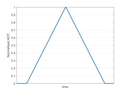
    With complex signals come complex receivers, and there several headaches when it comes to M-code receiver design. The first is the nature of the BOC signal itself, which has a complex correlation function. Consider Figure 3, which shows the autocorrelation function (ACF) of the traditional civilian C/A code signal. The single peak of the function makes acquisition and tracking a simple process; traditionally early, prompt and late (E,P,L) correlator arms can be used in the tracking process.

    Figure 4. L1Cd ACF.
    Figure 4. L1Cd ACF.

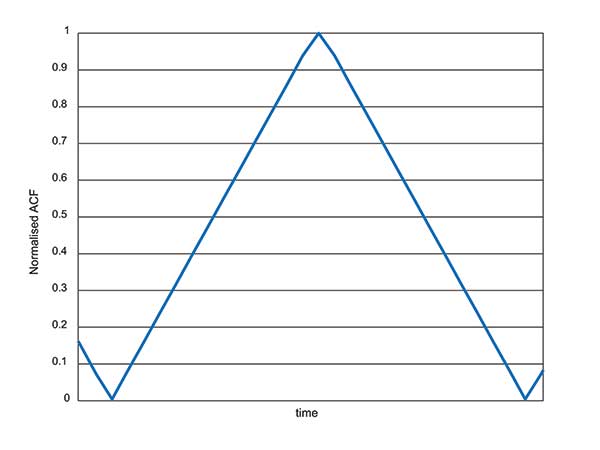
    The newer BOC-type signals have a more complex ACF. Figure 4 shows the ACF of the new L1Cd civilian GPS signal, which uses a form of BOS(1,1) modulation. In addition to the main lobe, there are now two side lobes. Receivers must be careful not to lock on to one of the side lobes instead of the main lobe: the receiver architecture starts to become a little more complex.

    Figure 5. M-code ACF.
    Figure 5. M-code ACF.

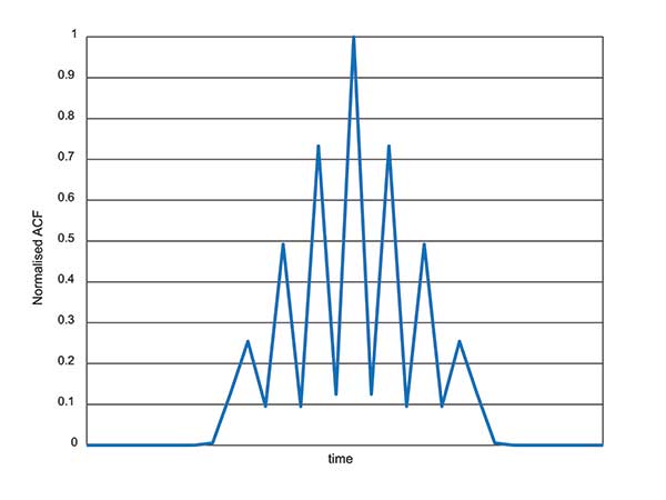
    Now consider the ACF of the M-code signal, shown in Figure 5. Like other high-order BOC-type signals, M-code exhibits multiple lobes in the ACF, making robust acquisition and tracking a far more troublesome process. Furthermore, the high bandwidths require high sample rates, which lead to higher power consumption in the hardware.

    Another major headache associated with M-code receivers is, of course, the encryption process. Not because encryption is difficult, but again because of the power consumption implications. Consider that each GPS receiver needs to run an encryption engine instance, for each satellite it might wish to receive. Running a high-grade encryption algorithm at a high chipping rate, for a dozen satellites, is a power-consuming process. For dismounted soldiers with limited battery capacity, this is a big deal.

    Some people argue that the high-grade encryption process for M-code is too complex. Consider why we want to encrypt a GNSS signal in the first place: firstly to prevent someone from spoofing our signal, and secondly to prevent unauthorised users from using the service. Given that the encryption keys are rolled regularly, how much does it matter if an adversary manages to compromise the encryption? This isn’t a communications security problem: we are not talking about loss of classified information, so there’s an argument that a simpler, less power-hungry form of encryption might have been used instead.

    ANTI-JAM ANTENNA COMPATIBILITY

    Although M-code offers a certain level of jamming resistance, it is still vulnerable to attacks. As a signal it might have a bit more power, and a bit more bandwidth, than some other signals. But it is, after all, still a GNSS signal, and it can be jammed by an adversary. Where an operational threat analysis indicates that an increased level of jamming resistance is required, then M-code receivers need to be integrated with anti-jam antennas.

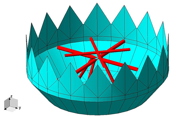
    Anti-jam antennas, usually referred to in the GNSS community as controlled reception pattern antennas (CRPAs), have been the anti-jam tool of choice for several decades now. I overviewed these in an April 2017 newsletter column. CRPA manufacturers have had to ensure that their products are “M-code ready,” such that they can be seamlessly attached to M-code receivers as and when they appear.

    This hasn’t been a recent process: as far back as 2002, the GAS-1 antenna (Raytheon) underwent a series of qualification tests to ensure compliance with M-code. Around 2005, the ADAP antenna (also Raytheon) was launched with a host of M-code features — again an illustration of just how slow the M-code program has moved, given that other technology has been “M-code ready” for 10 or 15 years already.

    What’s involved in making a CRPA M-code compatible? Firstly the increased bandwidth: the antenna electronics must digitize the wider bandwidths. Along with the wider bandwidth comes new filtering shapes to ensure optimum performance.

    Space-time adaptive processing (STAP) and space-frequency adaptive processing (SFAP) techniques potentially require more taps to ensure high null depths can be maintained across the full bandwidth. The increased power of the M-code signal, particularly if features like spot beam are used, presents another complication to CRPAs: they must not treat the high-power satellite signals as jammers, and try to remove them.

    Testing CRPAs presents a challenge to manufacturers: how do you prove that your antenna doesn’t corrupt the M-code signal, when there’s no M-code signal to test it with? To work around this issue, pseudo M-code signals have been used for testing, where representative BOC(10,5) signals without the real encryption are passed through the CRPA and examined for distortion.

    RECEIVER DEVELOPMENT STATUS

    Due to the security considerations surrounding M-code, only three US organizations are authorized to produce modules: Collins Aerospace, Raytheon and L3. Here are the answers from Collins Aerospace and L3, the answers from Raytheon will appear in later issue.

    What are the technical challenges associated with developing an M-code receiver?

    Collins Aerospace. The Collins Aerospace Modernized GPS User Equipment (MGUE) Increment 1 development like the SAASM PPS receiver developments faced very challenging technical requirements to support our war fighter needs in an ever-evolving threat environment. Like other complex developments the challenges are initially technical and then transition to integration/test and certification. On the technical front optimizing receiver performance balanced against power consumption are always at the forefront. In addition, it is important to maximize backwards compatibility so as to minimize downstream integration costs while adding an entirely new signal that runs in parallel to the existing system. Collins Aerospace is pleased with the technical development and are actively supporting the integration with both receivers and technical support.

    To date, we have delivered more than 770 MGUE receivers to the Air Force to support Air Force, lead platform and DoD-wide Integration and test. Soon the total will grow to nearly 1,100 receivers to support expanded integration and test following the completion of Collins Aerospace security certification.

    L3. M-code GPS User Equipment (MGUE) technologies exist today.L3’s Ground Based GPS Receiver Application Module – Modernized (GB-GRAM-M) is a fully-functioning unit that is currently baselined and undergoing an independent Technical Requirements Verification (TRV) by the GPS Directorate.During TRV, each requirement from the Technical Requirements Document (TRD) is independently evaluated for compliance. Upon completion of the TRV, the design is baselined with complete documentation enabling platforms and prime equipment to integrate from a known baseline with low risk. Following integration, operational testing can start immediately to support fielding when M-Code Early Use (MCEU) becomes operational. The TRV of L3’s GB-GRAM-M is planned to be completed by the second quarter of 2019.

    L3 resolved numerous technical challenges in developing M-code GPS technologies. The first and ever-present challenge is changing and evolving requirements. Most of these requirement changes are in response to evolving threats that have driven changes into the GPS receiver and/or to higher-level systems. Asan example, the U.S. Army’s Assured PNT (A-PNT) is implementing M- code GPS along with external sensors to establish and maintain an assured solution even in GPS-challenged environments. Other challenging requirements include meeting the security requirements, implementing and testing anti-spoofing algorithms, and ensuring backward compatibility with legacy receivers.

    What are the intended platforms for your MGUE?

    Collins Aerospace. The Collins Aerospace MGUE receivers are intended to support all warfighter domains: ground, airborne, maritime and munitions to support compliance with Public Law 111-383 SEC. 913 issued in Fiscal Year 2011. Per this directive, M-code is intended for all DoD applications with the exception of passenger vehicles or commercial vehicles with GPS installed. Now that the satellite and control segments of the capability are coming on line, we are working diligently to ensure that user equipment is available for all domains.

    L3. L3 has products to meet current market demand. Under the MGUE program, L3 developed a GB-GRAM-M, which is a standard Modular Open Systems Architecture (MOSA) design. The GB-GRAM-M is designed to fulfill retrofit replacements of SAASM receivers, as well as being a primary component of A-PNT systems. L3’s M2GRAM ASIC is the core of our receiver, a GPS module that incorporates signal processing, cryptography, and positioning, velocity, and timing (PVT) processing. The M2GRAM ASIC is capable of being implemented in other form factors for applications beyond ground-based applications. As an example, the M2GRAM is implemented in a GPS receiver specifically designed for Precision Guided Munitions (PGM) applications and was used in a gun launched, guide-to-target demonstration operating as a PGM receiver.

    L3 is also augmenting the GPS receiver through the integration of several other technologies, including controlled reception pattern antennas with digital antenna electronics, inertial systems and external sensors, and GPS-denied capabilities. M-code technologies are being implemented in Mounted A-PNT Systems (MAPS), Dismounted A-PNT Systems (DAPS), and handheld systems to bring capabilities to the warfighter.

    What is the expected timeline for your MGUE development, acceptance testing, and delivery?

    Defense Advanced GPs Receiver (DAGR) from Collins Aerospace, equipping infantry and other warfighters. (Photo: Collins Aerospace)
    Defense Advanced GPs Receiver (DAGR) from Collins Aerospace, equipping infantry and other warfighters. (Photo: Collins Aerospace)

    Collins Aerospace. The Collins Aerospace receivers are supporting ongoing DoD integration and test and our MGUE Increment 1 program is aligned with the Air Force GPS Enterprise roadmap. Ultimately, the Department of Defense (DoD) M-code programs will set the production delivery schedules.

    We anticipate that the M-code production ramp-up and continued SAASM PPS receiver production will have a production overlap. Our Collins Aerospace in-house PPS GPS receiver manufacturing capability is ready to support the DoD demand for both M-code and SAASM. Collins Aerospace is fully committed to manufacturing Increment 1 M-code receivers to meet the warfighter’s needs across Airborne, Weapons and Ground, we know the transition from SAASM to M-code will take years. Therefore, Collins Aerospace will continue to manufacture SAASM receivers for years to come as the International MOD Policy for M-code use is still being formulated.

    L3. L3’s GB-GRAM-M is now available. L3 received security certification and approval in 2016 and TRV is planned for completion in the second quarter of 2019. With TRV, L3 is receiving a new security certification and approval of the latest receiver update. Government agencies, prime contractors and laboratories can order GB-GRAM-M now with delivery in the fourth quarter of 2019.

    What does testing and verification process involve?

    Collins Aerospace. As with any Precise Positioning Service (PPS) GPS development, the testing involves functional verification of the receiver in a wide variety challenging of environmental, thermal, electromagnetic interference/ high-intensity radiated field (EMI/HIRF) environments. Collins Aerospace is leveraging proven test and verification approaches founded upon our long history of successful product introductions and field performance. As this is a PPS receiver it is also essential the receiver design comply with the government’s required Security Approval process.

    L3. The testing and verification of L3’s GB-GRAM-M included internal testing and independent testing through the GPS Directorate’s TRV process. Further risk reduction testing within the MGUE program is planned as Phase IV testing where the GB-GRAM-M is integrated into a lead platform for the U.S. Army and a lead platform for the U. S. Marine Corps. An operational assessment is performed on both lead platforms to assure common problems associated with integration and operational testing are addressed prior to implementing M-Code GPS Receivers across all of the platforms.

    Will the MGUE be compatible with CRPA anti-jam antennas; are there any special considerations for this?

    Collins Aerospace. The Collins Aerospace product family includes our Digital Integrated Anti Jam Receiver (DIGAR) product family that leverages CRPA anti-jam antennas for enhanced anti-jam (AJ) performance. Our DIGAR AJ technology enhances the performance with fixed reception pattern antenna (FRPA), CRPA and is compatible with all PPS waveforms. Regarding the interfaces between the receiver and the anti-jam antenna electronics, a GPS receiver with a standard RF interface is compatible with a CRPA in nulling mode and FRPA antennas. Advanced capabilities such as beamforming/beamsteering require tight coordination and additional interface with the GPS receiver.

    L3. The GB-GRAM-M is designed to operate with a fixed reception pattern antenna (FRPA). A CRPA antenna using digital antenna electronics to generate signals matching the characteristics of a FRPA is fully compatible with the GB-GRAM-M. With a higher level of integration of a GPS receiver and a CRPA, the system capabilities are greatly enhanced. L3 has performed this integration and can perform advanced capabilities such as angle of arrival and beamforming using M2GRAM, digital antenna electronics, and CRPA technologies. These capabilities can be found in L3’s Mounted Assured PNT System (MAPS) and Anti-Jam Antenna System (AJAS) products.

    Army Stryker ground combat vehicle. (Photo: Karolis Kavolelis / Shutterstock.com)
    Army Stryker ground combat vehicle. (Photo: Karolis Kavolelis / Shutterstock.com)

    OPERATIONAL DEPLOYMENT

    The U.S. Air Force GPS Directorate provided answers to the following questions regarding MGUE.

    Which platforms will be equipped with M-code-capable MGUE, and how many of each?

    GPS Directorate. The Air Force is developing M-code-capable GPS receivers under the MGUE Increment 1 program. The receivers in development will be provided to four service-specific lead platforms for integration, developmental, and operational testing. Lead platforms are:

    • the Army Stryker ground combat vehicle,
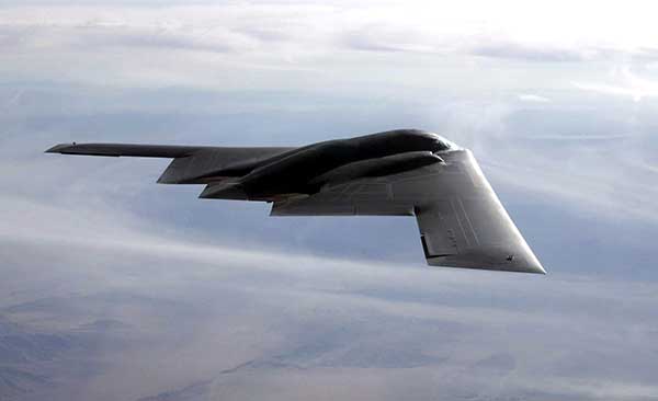
    • the Air Force B-2 Spirit bomber,
    • the Marine Corps Joint Light Tactical Vehicle (JLTV),
    • and the Navy Arleigh-Burke class destroyer (DDG).

    Following the lead platform efforts, procurement of M-code-capable GPS receivers will be decided by the Services and executed by individual platforms and programs.

    What are the timelines for rolling out M-code on these platforms?

    GPS Directorate. Early integration and test activities have already begun for each MGUE lead platform. Operational testing is expected to begin in 2020 and complete in 2021, which is a key activity to enable the fielding of M-code-capable systems.

    B-2 Spirit multi-role bomber capable of delivering both conventional and nuclear munitions. In December 2017, the Air Force completed a series of successful flight tests of M-code GPS using a Raytheon Company receiver on board a B-2 Spirit at Edwards Air Force Base, California. (Photo: U.S. Air Force/Bobby Garcia)
    B-2 Spirit multi-role bomber capable of delivering both conventional and nuclear munitions. In December 2017, the Air Force completed a series of successful flight tests of M-code GPS using a Raytheon Company receiver on board a B-2 Spirit at Edwards Air Force Base, California. (Photo: U.S. Air Force/Bobby Garcia)

    What advantages will M-code bring, over existing military GPS receivers?

    GPS Directorate. Modernized GPS receiver cards under development with the Air Force MGUE Increment 1 program will enable the use of M-code and provide U.S. forces with enhanced position, navigation, and timing capabilities, in addition to improving resistance to threats, such as jamming efforts by adversaries.

    How will keys and key distribution be managed?

    GPS Directorate. None of this is publically releasable.

    Will M-code be made available to other friendly nations? If so, how is this managed?

    GPS Directorate. The current policy allows for the sale of M-code equipment to all 57 authorized GPS PPS nations. The M-code technology will be made available to these nations through the Foreign Military Sales process.

    USER PERSPECTIVE

    The Department of Defense supplied answers to the following questions for users and warfighters.

    What are the benefits you perceive will come from new M-code GPS equipment?

    DoD. Provides U.S. forces with enhanced position, navigation, and timing capabilities, in addition to improving resistance to threats, such as jamming efforts by adversaries.

    Will it change how you perform military operations, or enable any new ones?

    DoD. Modernized GPS receivers provide the next-generation GPS capabilities to the warfighter. Operational testing will enable the services to determine operational utility of MGUE. It will ensure our soldiers, sailors, airmen, and marines have the ability to get in, accomplish their mission, and get home accurately.

    How will M-code-based GPS receivers be brought into operational service? Will there be a mass upgrade of assets, or a phased introduction?

    DoD. Procurement of M-code-capable GPS receivers will be decided by the Services and executed by individual platforms and programs.

  • UK tests tracking UGVs in military exercise

    UK tests tracking UGVs in military exercise

    In December 2018 near Salisbury, England, four Milrem Robotics’ and QinetiQ TITAN unmanned ground vehicles (UGVs) were put through three weeks of rigorous tests by British troops during the Army Warfighting Experiment 2018 (AWE18).

    The goal was to determine how new unmanned technologies can enhance soldier’s survivability and effectiveness on the modern battlefield.

    The modular base can be adapted for various missions, including casualty retrieval. (Photo: Milrem Robotics)
    The modular base can be adapted for various missions, including casualty retrieval. (Photo: Milrem Robotics)

    The test was conducted in three phases: conduct combat operations without the benefit of new technologies; conduct combat operations using new technologies but without changing tactics; and, lastly, conduct combat operations using new technologies and adapting tactics according to the capability that the new technology provides.

    The UGVs were used in a number of different roles with missions conducted in urban, open and forested terrain.

    In remote-control mode, a command-and-control station allows the operator to receive real-time sensor data from the UGV and to transmit command data to the vehicle through a tactical data link. Various third-party sensor packages can be installed.

    Of the four Milrem UGVs, two were deployed by Milrem Robotics and two by QinetiQ. The Milrem-fielded systems included one configured as a casualty evacuation and logistical support unit and a second unit equipped with a tethered multi-rotor drone pod provided by Threod Systems.

    One of the four UGVs was TITAN Strike, a prototype system carrying a Kongsberg remote weapon station, fully controlled by a remote operator and using QinetiQ’s Pointer system as a means of integrating the capability with dismounted infantry.

    The second system, TITAN Sentry, also enabled with Pointer, featured a Hensoldt-provided sensor suite including electro-optical and thermal-imaging cameras and a battlefield radar.

  • GPS III finally aloft, benefits on the way

    SpaceX’s Falcon 9 rocket orbited the first GPS III satellite on Dec. 23, 2018. (Photo: SpaceX)
    SpaceX’s Falcon 9 rocket orbited the first GPS III satellite on Dec. 23, 2018. (Photo: SpaceX)

    On December 23, the first GPS III satellite entered an orbit around Earth, after a five-day delay. This first of a new breed of GPS satellite also experienced a four-year delay, with its original launch scheduled for 2014.

    While the system has experienced more than its share of problems, at the start of a new year I want to focus on the benefits to come.

    Few of us realized how much our lives would change when the first GPS satellite was launched in 1978. GPS III could bring about a similar trajectory of changes. Civilians can expect a more reliable and accurate service. The smartphone message “searching for signal” could become a dim memory.

    GPS III signals will be three times more accurate than the current GPS Block II models. The navigation payload has more than three times reduction in range error and up to eight times increase in power — its signals should be much easier to pick up under tree canopy, within urban canyons and inside buildings.

    GPS III also has four civilian signals. The L1C signal is interoperable with international GNSS, meaning users can receive signals from any country’s satellites. Also, using two civilian signals means GPS III can directly detect and correct ionospheric errors.

    In addition to a standard wide-angle antenna for broad coverage, the GPS III satellites include a high-gain directional antenna that will operate with 100 times (+20 dB) the power of the wide-angle antenna, and will be exclusively for use with M-code (military) transmissions. This directional antenna’s spot beam covers an area 120 miles at high power— boosting the power of military GPS signals by 100 times in specific regions, making military GPS even harder to jam.

    These advantages may not reach the battlefield for a decade. The new constellation will take time to build. The GPS III constellation is projected to be fully capable in June 2023, when 10 Block IIIA satellites are expected to be in orbit. Ten follow-on satellites are planned to be placed into orbit from 2026 to 2034.

    Back here on Earth, equipment makers will need time to develop and supply warfighters with military GPS user equipment (MGUE) that can take advantage of all that GPS III has to offer.

  • Boundless receives nod from U.S. Army for desktop GIS software

    Certificate of Networthiness accreditation affirms U.S. Army’s use of Boundless Desktop for battlespace awareness in warfighter missions.

    Boundless Desktop has received the U.S. Army Certificate of Networthiness (CoN), an accreditation that ensures the product meets Department of Defense (DoD) and Army guidelines, regulations and requirements. The CoN verifies compliance with stringent DoD and Army requirements for security, sustainability and usability.

    Boundless Desktop is a native, cross-platform desktop geospatial information system (GIS) built upon proven open source software, including QGIS, PgAdmin, Qt Designer and GDAL/OGR. The product builds maps, manages data, models and analyzes, and disseminates results with users globally.

    Desktop is used to conduct geospatial analysis to include creation of common operating pictures, route and area analysis, and other geospatial intelligence operations.

    Desktop integrates government and geographic standards for cartographic styles and rules, combines and models spatial data in ways that generate new insights through workflow modeling, provides analytical tools and scripts for terrain and data analysis, and provides access to various open source formats for data and product sharing.

    Federal agencies are collecting and storing more location data and imagery than ever before, and timely and accurate geospatial intelligence is critical to making decisions that impact safety, security and quality of life. Public accountability means that agencies must be mindful of directing costs away from necessary tasks.

    Boundless provides federal agencies with enterprise-grade, fully supported versions of proven open source software along with reliable, expert help from feature development to production support. Interoperability is built right in, ensuring that geospatial data and analysis is accessible across agencies and divisions, the company said. Open source technology offers the flexibility needed to leverage geospatial data now and when needs or demands change. Expenses are predictable and manageable, freeing resources for mission-critical operations.

    “The use of automated data analysis and analytical tools is essential for developing situational awareness and a common operating picture of battlespace in our warfighter missions,” said Jason Lee Smith, security specialist, Counter Explosive Hazards Center, U.S. Army Fort Leonard Wood. “Timely and accurate geospatial intelligence provided by Boundless allows us to make mission-critical decisions that impact safety and security, and the software’s flexibility and interoperability means that we can consistently rely on it both in our day-to-day operations and when there are spikes of activity.”

    “Boundless is committed to delivering open and scalable GIS solutions that empower our users to understand the world around them through geospatial intelligence,” said Andy Dearing, CEO, Boundless. “The Army CoN assures that Boundless Desktop is safe, sustainable and easy for federal agencies to use, and we’re proud to have achieved this validation for our solutions in the federal government space.”

  • U.S. Army invests in virtual reality training

    U.S. Army invests in virtual reality training

    The U.S. Army considers virtual reality training as an important path ahead to prepare warfighters.

    The U.S. Army awarded Bohemia Interactive Simulations (BISim) a major extension to demonstrate technologies for a cloud-enabled, virtual world training capability.

    BISim is a global developer of advanced military training and simulation software.

    The contract award helps meet the requirements of the Army’s Synthetic Training Environment (STE) initiative. STE aims to converge virtual, constructive and gaming training environments into a single unified architecture.

    The ambitious STE project will enable simulation systems Army-wide to leverage a persistent virtual world for any imaginable training need, including support for multi-domain operations incorporating cyber and space.

    Central to STE is a cloud-enabled One World Terrain (OWT) that will let warfighters conduct virtual training and complex simulations anywhere on a virtual representation of the Earth. OWT will leverage cloud technologies to deliver to the point of need, ensuring a common and high-fidelity whole-Earth terrain representation for a multitude of different simulation systems.

    The Synthetic Training Environment will assess Soldiers in enhancing decision-making skills through an immersive environment. (Photo: U.S. Army)
    The Synthetic Training Environment will assess Soldiers in enhancing decision-making skills through an immersive environment. (Photo: U.S. Army)

    “The U.S. Army’s vision for STE marks a monumental change in how they acquire, develop and deliver new simulation and virtual training technologies to soldiers,” said Pete Morrison, BISim’s co-CEO and chief product officer. “We’re honored to be selected to assist the Army in developing innovative solutions that will shape the future of how virtual training is used to enhance operational readiness.”

    BISim has been developing its next generation of simulation technologies since 2014. The new technology suite includes a cutting-edge, military-specific whole-earth game engine, deterministic AI, an efficient geospatial terrain server and component-based development technology.

    BISim technology underpins funded research and development for One World Terrain. Additionally, BISim recently demonstrated Reconfigurable Virtual Collective Trainer (RCVT) prototypes for STE. The latest OTA extension is a significant ramp up in the breadth and ambition of the technology being demonstrated.

    BISim’s STE offering includes four core technologies uniquely suited to meeting future military simulation requirements (including U.S. Army requirements).

    VBS Blue. A high-performance, whole-planet data ingestion and rendering engine with a very high level of procedural detail, designed to ingest any conceivable terrain data format as well as source data directly. VBS Blue will support networked (cloud) terrain paging and geo-specific insets as well as the latest graphics technologies. It provides photorealistic detail, and includes a massive vegetation library representing every region on Earth. The technology is highly applicable across all types of image generation and is optimized for many AR/VR applications.

    STEWS. A geospatial data server that provides efficient networked access to the various data sources required for rendering applications. STEWS provides a curated database of terrain data layers that can be streamed into any STE-connected client application at run time (including non-BISim applications). Any application connected to STEWS can stream high fidelity terrain data in a performant manner. Both new and legacy terrain formats are supported through new STEWS plug-ins.

    VBS Control. High fidelity, doctrinal and deterministic entity-level artificial intelligence that is uniquely suited to operation on whole-earth terrain. VBS Control runtime offers highly efficient real-time path planning that allows AI to move seamlessly through open, urban and interior spaces. The VBS Control Editor allows powerful new AI behaviors to be developed at both the individual entity level and at higher levels of command for land, sea and air assets.

    Gears. A software development framework that defines a standard way for components to communicate through formal interfaces. Gears uses a component-based architecture to promote rapid development by building applications from self-contained systems and having them communicate via formally defined interfaces. This allows functionality to be reused and avoids the complexity of tightly coupled systems. See www.gears.studio for more information.

    The Army also selected BISim for a five-year contract to support their Games for Training Program and BISim’s technology is being rolled out on CCTT (the U.S. Army’s largest ground simulator training program).

  • Orolia introduces SecureFind wearable combat search-and-rescue beacon

    Orolia introduces SecureFind wearable combat search-and-rescue beacon

    U.S. Army photo by Spc. Javon Spence
    U.S. Army photo by Spc. Javon Spence

    Orolia has introduced its latest military technology innovation, the SecureFind Combat Rescue Beacon, at the 2018 AUSA Annual Meeting in Washington, D.C.

    In addition to protecting the most critical assets and leaving no one behind, combat search and rescue (CSAR) technology can significantly enhance military operations by avoiding the loss of sensitive information and technology, avoiding hostage situations and helping to prevent conflict escalation.

    SecureFind is based on Orolia’s search-and-rescue technology suite, selected by military forces for CSAR missions. The wearable base unit includes an open channel search-and-rescue solution, for military use in training or test mode. It can also be configured with a customer-defined, secure channel solution for covert operations.

    The versatile CSAR solution operates with a silent, push-button functionality that does not require voice activation. SecureFind enables military forces to precisely and safely execute CSAR missions, with optional Assured PNT (positioning, navigation and timing) technology that prevents GPS signal interference, spoofing and jamming, the company said.

    “There is no greater need for urgency, stealth and precision than when military personnel are isolated in rugged environments or behind enemy lines,” said Paul Zweers, Orolia’s vice president of defense programs.

    “Software-defined, wearable communications technology is now more important than ever on today’s air, land, sea and cyber battlefields,” added Orolia CEO Jean-Yves Courtois. “CSAR missions are just the beginning of potential uses for this resilient military technology, which can ensure reliable positioning, navigation and timing data in any operating environment. Orolia’s solutions are tailored to support today’s soldiers and engineered with a view toward the future of global military networks.”

    According to Orolia, the standard SecureFind solution is available at a price point that could enable thousands of warfighters to benefit from the new battlefield technology. More advanced functionality is also available, such as the ability to change signals on-the-go for additional security, to detect and mitigate GPS jamming and spoofing, and to generate important strategic information such as virtual battlefield maps of jamming and spoofing activity.

    Orolia offers a cost-effective, modular approach to assured PNT, with a flexible, open architecture that integrates easily with legacy systems. This layered platform meets critical technology requirements without over-engineering a solution that is complex, expensive and difficult to maintain.

    Additional SecureFind product information is available at the AUSA Annual Meeting, Orolia booth #8051.

  • Aerospace wins U.S. Army contest to bring AI capabilities to soldiers

    Aerospace wins U.S. Army contest to bring AI capabilities to soldiers

    A team from Aerospace Corporation won a U.S. Army challenge designed to identify artificial intelligence and machine learning tools that could improve the speed and accuracy of electronic warfare operations.

    The Army Signal Classification Challenge invited participants to prove they had the best artificial intelligence and machine learning algorithms for performing “blind” radio frequency signal classification quickly and accurately.

    An Interim Armored Vehicle "Stryker" and AH-64 Apache helicopters with Battle Group Poland move to secure an area during a lethality demonstration as part of Saber Strike 18 in June 2018. (Photo: U.S. Army/Spc. Hubert D. Delany III, 22nd Mobile Public Affairs Detachment)
    An Interim Armored Vehicle “Stryker” and AH-64 Apache helicopters with Battle Group Poland move to secure an area during a lethality demonstration as part of Saber Strike 18 in June 2018. (Photo: U.S. Army/Spc. Hubert D. Delany III, 22nd Mobile Public Affairs Detachment)

    The goal was to find solutions that could reduce the cognitive burden placed on electronic warfare soldiers by identifying signals of interest in the electromagnetic spectrum.

    The Army , Rapid Capabilities Office (RCO) launched the challenge because the classic signal detection process is no longer efficient in understanding the vast amount of information presented to electronic warfare soldiers on the battlefield by an ever-increasing number of satellite signals, radars, phones and other devices.

    More than 150 teams from across universities, laboratories, industry and government participated. The first-place award of $100,000 went to Platypus Aerospace from Aerospace Corporation, a federally funded research and development center.

    Second place, with an award of $30,000, went to TeamAU, made up of a team of individual Australian data scientists. Third place and $20,000 went to THUNDERINGPANDA of Motorola Solutions.

    “The amount of interest and quality of performance was remarkable, including from nontraditional organizations,” said Rob Monto, Emerging Technologies director for the RCO. “In doing this as a challenge, instead of a traditional Request for Information, we were really modeling what industry does to get at a problem quickly. It was performance-based, open to anyone and implemented without a lot of cost or burden placed on those entering. And now, in a matter of less than four months, we know mathematically who has the best performance for this initial step of applying AI and machine learning to signal classification.”

    The challenge, which opened on April 30 and closed on Aug. 13, gave participants 90 days to develop their models and work with training datasets provided by the RCO. That was followed by two test datasets of varying complexity that were the basis for judging submissions.

    Participants’ overall challenge score was based on a combined weighted score for both test datasets. Participants were also able to see how they were performing in relation to others in real time, via the participant leaderboard.

    “This challenge targeted the upfront data collection, which is traditionally very labor intensive and time consuming,” Monto said. “Now we have a very accurate, very rapid algorithm for a specific problem set. With this research done on the front end, we can move forward with trying to build and integrate it into a real solution for the Army.”

    A second phase of the competition is planned and details will be announced later this year.

    “We’re thrilled to see our team win this competition through their novel application of artificial intelligence to secure the use and protection of the radio frequency spectrum,” said Steve Isakowitz, Aerospace president and CEO. “Their accomplishment is another great example of how Aerospace is employing cutting-edge technology to advance next-generation capabilities for the warfighter while solving one of our customer’s most difficult challenges.”

    Aerospace engineers, named “Team Platypus,” win the Army AI Challenge. From left: Eugene Grayver, Alexander Utter, Andres Vila, Donna Branchevsky, Esteban Valles, Darren Semmen, Sebastian Olsen, Kyle Logue (not pictured). (Photo: Aerospace Corp.)
    Aerospace engineers, named “Team Platypus,” win the Army AI Challenge. From left: Eugene Grayver, Alexander Utter, Andres Vila, Donna Branchevsky, Esteban Valles, Darren Semmen, Sebastian Olsen, Kyle Logue (not pictured). (Photo: Aerospace Corp.)

    The group, known as “Team Playtpus,” consists of eight Aerospace communications systems and artificial intelligence engineers: Andres Vila, Kyle Logue, Esteban Valles, Donna Branchevsky, Sebastian Olsen, Alexander Utter, Darren Semmen and Eugene Grayver.

    Out of more than 150 overall participants, including 49 teams that actively competed in the challenge, the Aerospace team won by correctly detecting and classifying the greatest number of radio frequency signals using a combination of signal processing and AI technologies.

    “In its challenge, the Army RCO released a training set with synthesized data that the teams used to build their algorithms,” said Andres Vila, Aerospace team lead. “Our goal was to combine the team’s deep history and expertise in advanced satellite communications with our practical knowledge of the latest in machine learning and deep neural networks to provide a best-in-class solution.”

    Vila added, “This win means that we have built a team that can excel in this new and exciting field of machine learning and specifically deep learning solutions for communication problems.”

  • U.S. Army solicits PNT solutions for warfighters

    U.S. Army solicits PNT solutions for warfighters

    The U.S. Army is soliciting proposals for research, development, design and testing that directly supports battlefield technologies in the area of positioning, navigation and timing (PNT).

    Broad Agency Announcement (BAA W56KGU-18-R-PN22) was issued by the U.S. Army’s Communications-Electronics Research, Development and Engineering Center (CERDEC) on Nov. 24 through FedBizOpps.gov.

    CERDEC — based at the Aberdeen Proving Ground in Maryland — aims to discover technical approaches to improve and enhance current and future land warrior capabilities, flexibility and responsiveness in line with its strategic vision for enhancing warfighter capabilities to operate in both symmetric and unsymmetrical environments.

    GPS-denied environments. “The goal is to support CERDECs Strategic Thrust for PNT by providing technical and operational capabilities that enables the soldier to continue their operations in hostile RF and GPS-denied environments,” reads the BAA. “Proposed technical approaches may apply to operations both before and after the cessation of hostilities.

    “This announcement emphasizes approaches that address the very different challenges presented by urban fighting and dramatically enhance warfighter capabilities, for example, the ability to interact, maneuver and operate under a time constrained environment. These changes should generally result in lower casualties, lower collateral damage, and the effective use of combat power.

    “The specific topics of interest revolve around the research and development of technologies may provide revolutionary improvements to the entire spectrum of PNT.”

    Soldiers with 18th Military Police Brigade, assault opposing enemy threats during an Urban Operations training at the 7th Army Training Command’s Grafenwoehr Training Area, Germany, Oct. 20, 2017. (U.S. Army photo by Spc. Javon Spence)

    CERDEC’s plan is to support multiple and potentially multiphase efforts that pursue the design, development, integration and demonstration of critical and enabling technology and system attributes pertaining to PNT. Proposed efforts will primarily be of service and material with aims at resolving technical barriers.

    Proposals. Proposals submitted should range in scope from study and analysis type work with limited data and deliverables, to larger efforts for component developments, techniques and demonstrations with breadboard or prototype-style deliverables.

    The contracts are expected to be cost-plus-fixed-fee, but can be negotiated.

  • Orolia’s VersaPNT helps soldiers navigate battlefields without GPS

    Orolia’s VersaPNT helps soldiers navigate battlefields without GPS

    Orolia, through its Spectracom brand, has launched VersaPNT. VersaPNT provides virtually failsafe battlefield navigation, even in GPS-denied environments, to protect critical networks with Assured PNT technology, the company said.

    The new, ground, air or sea vehicle-mounted solution is designed for military environments, with a ruggedized, compact, low-power and lightweight form factor.

    Today, military vehicles are portable networks, providing seamless connections with U.S. headquarters, regional command posts and individual soldiers. Remote areas are challenging environments for military networks, and enemy forces are jamming, spoofing and disrupting operations.

    “VersaPNT provides continuous mission assurance and C4ISR support, even in hostile environments,” said Rohit Braggs, Orolia vice president, PNT networks and sources. “This innovative technology solution protects critical networks for complex military and homeland security land, air and sea operations.”

    Every minute counts on the battlefield, and VersaPNT provides critical decision support with real-time situational awareness to facilitate a rapid response, according to the company. This lifesaving technology can also help keep soldiers and civilians out of harm’s way, while ensuring continuous tracking of friendly and enemy forces.

    VersaPNT provides essential command and control, navigation, communication and electronic intelligence support for U.S. and allied military, homeland security, first responder, civilian agency, special operations and intelligence missions.

    Demonstrations are available at the AUSA Annual Meeting, Orolia Booth #2944.

  • Comtech contracted by U.S. Army to sustain Blue Force Tracking

    Comtech contracted by U.S. Army to sustain Blue Force Tracking

    Comtech Telecommunications Corp.‘s Command & Control Technologies group — part of Comtech’s Government Solutions segment — has been awarded contract modifications totaling $4.2 million.

    The contract modifications are part of a five-year sustainment support contract for the U.S. Army’s Project Manager Mission Command (PM MC) Blue Force Tracking (BFT-1) program.

    BFT-1 is a battle command, real-time situational awareness and control system. Under the five-year BFT-1 sustainment contract, Comtech performs engineering services, satellite network operations and program management.

    A U.S. soldier preparing his Blue Force Tracker before departing Camp Victory, Iraq in 2005.
    (Photo: Petty Officer 1st Class Brien Aho, U.S. Navy)

    Comtech continues to perform engineering services, satellite network operations and program management through a Firm Fixed Price (FFP) contract with Time & Materials (T&M) and Cost Reimbursement elements. The base performance period began April 15, 2017 and ends April 14, 2018, and the contract provides for four twelve-month option periods exercisable by GSA.

    Of this amount, $3 million was received during its fourth quarter of fiscal 2017 and $1.2 million was received during its first quarter of fiscal 2018. This additional funding applies to the original award in April 2017, which today totals $7.7 million of the total potential value of the base year. These modifications fulfilled the government’s obligation to fund the Firm Fixed Price (FFP) portion of the contract.

    “We are pleased that our Army customer recognizes the value of Comtech’s services,” said Fred Kornberg, president and CEO of Comtech Telecommunications Corp. “Comtech is committed to providing the Army and its soldiers with the highest level of support to enable them to complete their missions.”

    Blue Force Tracking systems consist of a computer, used to display location information, a satellite terminal and satellite antenna, used to transmit location and other military data, a GPS receiver (to determine its own position), command-and-control software (to send and receive orders, and many other battlefield support functions) and mapping software, usually in the form of a geographic information system (GIS) that plots the BFT device on a map.

    The system displays the location of the host vehicle on the computer’s terrain-map display, along with the locations of other platforms (friendly in blue, and enemy in red) in their respective locations.

    BFT can also be used to send and receive text and imagery messages, and Blue Force Tracking has a mechanism for reporting the locations of enemy forces and other battlefield conditions (for example, the location of mine fields, battlefield obstacles or bridges that are damaged.)

    The Command & Control Technologies group is a provider of mission-critical, highly-mobile C4ISR solutions. Comtech Telecommunications Corp. designs, develops, produces and markets innovative products, systems and services for advanced communications solutions. The Company sells products to a diverse customer base in the global commercial and government communications markets.

  • Lockheed Martin awarded GPS M-code early-use ground system upgrade

    Lockheed Martin awarded GPS M-code early-use ground system upgrade

    The U.S. Air Force has awarded Lockheed Martin a $45.5 million contract to provide military code (M-code) early use (MCEU) capability to the Global Positioning System (GPS).

    Part of the Air Force’s overall modernization plan for the GPS, M-code is an advanced, new signal designed to improve anti-jamming and protection from spoofing — as well as increased secure access — to military GPS signals for U.S. and allied armed forces.

    MCEU will provide command and control of M-code capability to eight GPS IIR-M and 12 GPS IIF satellites on orbit, as well as future GPS III satellites, which the Air Force expects will begin launching in 2018.

    MCEU is envisioned as a way to accelerate M-code’s deployment to support testing and fielding of modernized user equipment in support of the warfighter.

    The Military Code (M-Code) Early Use (MCEU) contract will accelerate deployment of command and control of M-code capability to GPS IIR-M and GPS IIF satellites currently on orbit, as well as future GPS III satellites (like GPS III SV02 above). (Photo: Lockheed Martin)

    The U.S. Air Force’s MCEU contract directs Lockheed Martin to upgrade the existing Architecture Evolution Plan (AEP) Operational Control System (OCS), allowing it to task, upload and monitor M-code within the GPS constellation. The contract includes new software and hardware development that will be deployed in 2019 to worldwide ground facilities that support the Air Force’s GPS.

    “When people think of GPS, they often think of the satellites that provide the signals, but do not remember the important ground system behind it,” said Mark Stewart, Lockheed Martin’s vice president for Navigation Systems. “We recognize the ‘ground’ is critical for any major space mission constellation and we are proud that we can help the Air Force with this part of their GPS modernization plan.”

    The AEP OCS — maintained by Lockheed Martin under the GPS Control Segment (GCS) Sustainment Contract — controls the 12 GPS IIR, 8 IIR-M and 12 IIF satellites in orbit today. The company has successfully implemented several recent projects to modernize and sustain the system for the Air Force.

    In June, Lockheed Martin deployed the first of its state-of-the-art GPS Monitor Station Technology Improvement Capability (MSTIC) receivers at Cape Canaveral Air Force Station. The software-defined MSTIC system replaces 30-year-old hardware, positioning the Air Force to take advantage of commercial off-the-shelf technology enhancements in processing power, reliability and cybersecurity in the future. Six Air Force AEP OCS monitoring stations around the world will receive the MSTIC upgrade by the end of 2017.

    In February 2016, the Air Force awarded Lockheed Martin the GPS III Contingency Operations (COps) contract to upgrade the AEP OCS with new capabilities so it could support the more powerful, next-generation GPS Block III satellites. The COps program passed a successful Critical Design Review milestone with the Air Force in December 2016.

    Also in 2016, under the GCS contract, Lockheed Martin completed the commercial off-the-shelf upgrade No. 2 (CUP2) project — part of a multi-year plan to modernize the AEP OCS’ technology and enhance the system’s ability to protect data and infrastructure from internal and external cyber threats, as well as improve its overall sustainability and operability. CUP2 is now fully operational and managing the current GPS constellation.

  • Army pseudolites: What, why and how?

    Army pseudolites: What, why and how?

    In the battle for reliable positioning and timing, the U.S. Army is engaged in a multitude of activities, including mounted and dismounted A-PNT (assured position, navigation and timing) systems, anti-jam technology and pseudolites.

    The idea is simple: Take some GPS satellites, and put them on or near the ground. Now you have a navigation system where you have full control over the locations and power of the transmissions. You can ensure that the transmissions reach places that GPS normally struggles with, such as deep urban canyons, forests and valleys.

    You can turn up the transmit power, so they are much harder to jam than spaceborne GPS signals. These pseudo-satellites, commonly referred to as pseudolites, have seen steady interest over the years for a variety of applications.

    Now the U.S. Army is pursuing the use of pseudolites as part of its initiative to maintain operation in GPS-denied environments.

    Pseudolite Basics

    There are various types, and use-cases, of pseudolites. In this column we’ll consider the direct-ranging pseudolite, which can be simply considered as a ground-based GPS satellite. If we deploy several pseudolites on the ground, we can imagine that a normal GPS receiver would be able to receive the GPS-standard transmissions and derive a position, just as we would from the space-based satellite transmissions.

    The fact that the pseudolites are ground-based introduces us to the first consideration: The locations of the transmitters are no longer described by orbital parameters. Instead of calculating the position of satellites, we need to describe the location of the pseudolites in geographical terms, perhaps with a fixed position described in Earth-centered, Earth-fixed (ECEF) coordinates.

    The transmitted navigation data message, which would normally contain almanac and ephemeris information, may now need to contain the geographical position of the pseudolite. Not a problem, but our GPS receivers will need a software upgrade to be able to handle this situation.

    The deployment of the pseudolites themselves poses an interesting problem. Imagine a military scenario, where the army is deployed to a region of interest. Navigation warfare is taking place, and GPS is frequently jammed in the region.

    High-power pseudolites are deployed to allow the army to navigate despite the jamming, using the same standard-issue GPS receivers that soldiers are familiar with.

    The first problem is, having placed your pseudolites in position, how do you know where they are?

    You might choose to place your pseudolites at locations that have previously been surveyed, so you know where they are in advance. But this isn’t likely, particularly if you’ve just moved your troops into an unfamiliar area. You might also want to move the pseudolites regularly, as the army moves to new ground. So the pseudolites need to determine their own position, and the easiest way for at pseudolite to determine its own position is with GPS, of course.

    Isn’t this a bit incestuous? If we’re using pseudolites because GPS is jammed, how does the pseudolite get its position? This is why military pseudolites will typically be fitted with some form of anti-jam technology, such as a controlled radiation pattern antenna. This allows the pseudolite to receive GPS satellite signals in the presence of jamming, determine its own position, and transmit that as part of its own navigation message.

    So, now that we can get pseudolite locations, the next consideration is: Where should pseudolites be placed?

    A-DOP-ting a Good Layout

    If you know about GNSS, you’ll be familiar with the concept of dilution of precision (DOP). This is essentially a measure of how accurate your position estimate is likely to be, due to the geometry of the satellites: a good wide spread of satellite positions gives us better accuracy.

    Figure 1. Poor satellite geometry, resulting in high DOP. (Image: Michael Jones)
    Figure 2. Good satellite geometry, resulting in low DOP. (Image: Michael Jones)

    The DOP can be easily calculated by forming a covariance matrix of the geometry, expressed in an appropriate coordinate frame. If (xn, yn, zn) denotes the position of the nth pseudolite, and (x, y, z) the position of the receiver, we can express the unit vectors from the receiver location to the pseudolite location:

    We then form a matrix of these unit vectors:

    Finally, we form the covariance matrix from which we can extract the DOP values:

    From the elements of this matrix we can determine the various DOP metrics. Let’s concentrate on horizontal DOP (HDOP), given by:

    When positioning using GPS satellites, we are blessed with a Walker constellation that generally gives us a nice spread of satellite locations (unless we’re in an urban canyon). On the battlefield, using pseudolites, we do not have the same luxury.

    Let’s consider a scenario: a conflict in Helmand province, Afghanistan. An operating base is established at Camp Shorabak, where a pseudolite is operating, and three further pseudolites are deployed in the field. This is shown in figure Figure 3.

    Figure 3. Scenario with four pseudolites. (Image: Michael Jones)

    Taking a look at Figure 4, we can see what this means for HDOP. The regions shaded green represent locations where our HDOP is less than 2.5, and the red areas represent an HDOP greater than 50.

    Soldier #1 is surrounded by the four pseudolites, which is a pretty nice arrangement: We get an HDOP of around 2.4. But if we now consider soldier #2, located a bit further out, we get a very different picture.

    Here we have an HDOP of 64, which is fairly terrible. It’s not really that surprising looking at the geometry — to soldier #2 the pseudolites all appear in a similar direction. Soldier #2 cannot expect to achieve good positional accuracy in this arrangement.

    Figure 4. HDOP for the Afghanistan scenario. (Image: Michael Jones)

    So getting a good geometric spread of ground-based pseudolite locations could be a bit of a challenge, especially if the operating area is constantly moving and changing. The next thing to think about is getting enough height.

    Getting the Height Right

    When we perform positioning using GPS, we typically track several satellites, which have a range of elevations. Many GPS receivers will choose to ignore the satellites at low elevations, such as those within 5 degrees of horizontal, because those satellites are generally the least reliable. They may be partially obscured, and subject to more noise and fading.

    Ground-based pseudolites all have very low elevations by definition. Unless the terrain is perfectly flat and smooth, pseudolites quickly become obscured. Even with flat ground, pseudolite signals will disappear behind the horizon after a few kilometers.

    Let’s go back to our Afghanistan scenario again. This time, instead of looking at DOP, let’s look at the geographical coverage of our four pseudolites. Here we’ll assume that our user, the soldier, is 2 meters (m) high, and the pseudolite antennas are mounted at a height of 20m above the ground. That’s pretty high — the army will need to erect some masts.

    Figure 5 shows what we get. The green areas are locations where our soldier can see all four pseudolites; yellow three, orange two, and red one. At all other locations, no pseudolite signals can be seen at all. You can quickly see that the range isn’t great — terrain, even small undulations in the ground, is a line-of-sight killer. Add some buildings and trees and the situation gets worse. Reduce the height of our pseudolites below 20m, and the situation gets worse. Soldier #1 can receive three pseudolite signals, but soldier #2 has no hope in this case.

    Figure 5. Pseudolite visibility at 20m antenna height. (Image: Michael Jones)

    Let’s raise the height of the antennas to a fairly crazy 100m above ground (Figure 6). As expected, we get much better coverage, but soldier #2 still has a problem. To get good signal coverage over any sizable area, you really do need to get those antennas as high as possible.

    Figure 6. Pseudolite visibility at 100-m antenna height. (Image: Michael Jones)

    Augmenting GPS

    Often, we don’t want to rely on pseudolite signals alone. If GPS is available, we clearly want to make use of it, and so we want to use a mixture of both GPS satellites and pseudolites. Consider working in a region of sporadic GPS reception, such as an urban environment or forest. We can usually receive a couple of good GPS satellites, but we also need a couple of pseudolites to help us get a complete navigation solution.

    Coming back to one of our original objectives, which is to avoid redesigning the GPS receiver hardware, we need to make sure that our receivers can receive and process both GPS satellite signals and pseudolite signals simultaneously. To achieve this, we can decide to make our pseudolites transmit GPS-standard signals, and make use of unassigned spreading codes to essentially create new satellites in the constellation.

    But we quickly run into a problem. GPS satellites are always a distance of around 20,000 kilometers away, and the received signal strength is also fairly constant: around –158.5 dBW. This is a very small signal, as we all know, sitting well below the noise floor. When we suddenly bring high-power pseudolites into the mix, we have quite a nasty problem to deal with.

    Near, Far, Wherever You Are

    Let’s say, for argument’s sake, we have a pseudolite transmitting with a power of 1 watt. Conducting a basic link budget analysis gives us the plot below and suggests that, at a distance of 10 km from the pseudolite, we can expect to receive the signal at around –112 dBW. This is way above our GPS satellite signal level, but might be manageable by a receiver. Now consider a receiver at a distance of 100 m from the transmitter: we receive a power of –72 dBW, which is huge.

    In our quest to augment GPS and make it more robust, we have in fact created a GPS jammer, and achieved exactly the opposite. As with any radio communications link, the received power is extremely sensitive to the distance (varying with the square of distance). In pseudolite terminology, this is known as the near/far problem.

    Figure 7. Theoretical received power for a 1-W pseudolite, under ideal conditions. (Figure: Michael Jones)

    The near/far problem has given engineers headaches for quite some time. Essentially, the problem comes down to: How can our GPS receivers handle such a massive dynamic range of expected signals? Especially if our objective is to avoid modifying the GPS receiver hardware, if at all possible.

    How can a receiver handle the high power of a close-up pseudolite, which is to all intents a jammer, whilst simultaneously receiving the tiny GPS satellite signals from space? Various solutions have been proposed over the years, but one of the current favorite techniques involves pulsing the pseudolite signal.

    The idea, then, is to only turn on the pseudolite periodically, essentially applying a duty cycle to the transmission. If a pseudolite isn’t transmitting, it can’t interfere with the normal GPS signals. There are a couple of things to take into consideration here:

    1. What should the pulse duty cycle be, to enable both satellites and pseudolites to be tracked?
    2. How does the GPS receiver behave when presented with alternating large and small signals?

    A mathematical analysis of duty cycle effects is beyond the scope of this column, but consider Figure 8 for a qualitative view. Here we have two pseudolites operating alongside GPS satellites. The duty cycle chosen here is for the pseudolite to be operational for 10% of a 1 millisecond integration period. This gives enough time, when the pseudolite is not transmitting, for the low-level GPS satellites to be tracked.

    The second pseudolite, which is closer and therefore higher power, transmits for a further 10% slot after the first pseudolite. You can see that each additional pseudolite eats into the time available for tracking GPS satellites, and degrades the signal-to-noise ratio. There are some tricks you can play, such as transmitting multiple pseudolites at the same time if you know they will be similar power levels, but it can get complicated.

    Figure 8. Received power versus time, for a pulsed pseudolite scenario. (Figure: Michael Jones)

    The Importance of Gain Control

    How the receiver copes with the large differences in received power level depends largely on the design of the RF front-end in the receiver. Most GPS receivers will have a certain amount of automatic gain control (AGC), which is a feedback loop designed to keep power levels constant. Many GPS receivers, though, simply aren’t designed with enough AGC to handle pseudolite-level signals (think GPS jammers again).

    Military receivers, though, tend to have greater RF handling capabilities, and more bits in the ADC, so are better-suited to the situation. It is then a question of making sure the AGC loop responds in an appropriate time, compared to the duty cycle of pulses.

    Figure 9 illustrates a slow AGC response, which is not particularly suitable. Compare this with Figure 10, where we have a fast AGC response, quickly adapting to the switches in power level. A receiver with this characteristic will be better able to track both pseudolite and satellite signals.

    Figure 9. Pulsed pseudolites with slow AGC response (in red). (Figure: Michael Jones)
    Figure 10. Pulsed pseudolites with fast AGC response (in red). (Figure: Michael Jones)

    Airborne Pseudolites

    If you’ve read this far, you’ll now know that the main problems with ground-based pseudolites are lack of good geometry, signal blocking by terrain, and the horrendous near/far issues. Wouldn’t it be nice if we could raise the pseudolites to a really high altitude, and all these problems would go away? Wait, that’s the GPS satellite constellation!

    Ok, let’s not put them that far up. But how about carrying pseudolites on high-altitude airborne platforms instead? Great idea, and that’s why this is a current thread of defense activity in various countries. High-altitude long-endurance (HALE) or HAPS (high-altitude pseudo-satellite; the clue is in the name) unmanned platforms can be used to carry pseudolites at high altitude.

    This solution can provide excellent coverage, the pseudolites can be repositioned as necessary, and the near/far problem is also far less pronounced.

    I leave you once again with our Afghanistan scenario, from the point of view of a high-altitude airship at 18,000 meters.

    Figure 11. High-altitude platform, potentially carrying a pseudolite at 18,000 m. (Image: Michael Jones)

    Figures: Michael Jones