NavStar — a deformation monitoring company — has joined the Terra Insights platform of geotechnical brands.
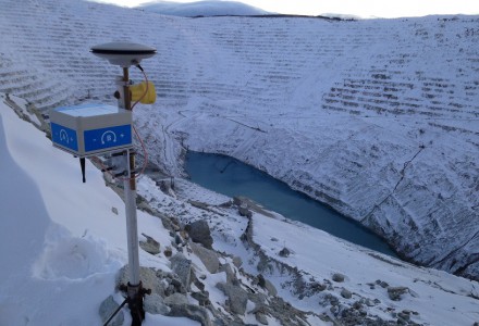
NavStar develops specialized hardware and software for automated detection of movement on slopes and structures, with an emphasis on GPS/GNSS sensors. It provides a scalable and modular data-collection and presentation software platform.
“NavStar perfectly complements Terra Insights’ vision of being the global platform to provide trusted geotechnical, structural and geospatial monitoring technology and data delivery solutions,” said Mark Price, CEO, Terra Insights. “NavStar’s specialized expertise in automated deformation monitoring systems from both a hardware and software perspective expands Terra Insights’ core capabilities while pushing us further into the future.”
NavStar’s team of surveyors, engineers, technologists and software developers has been providing specialized GPS/GNSS solutions, products and support to clients around the world since 2001.
NavStar’s specialized GeoExplorer and deformation monitoring products are used by the mining, oil and gas, power, construction and government sectors.
“We are excited to join Terra Insights,” said Glen Bjorgan, manager of Field Operations at NavStar. ”Over the years we have worked extensively with the companies that make up the Terra Insights platform. Through that experience, we know that Terra Insights will be a great fit for NavStar and our customers.”
What works well and what needs improvement in the GPS program regarding technology, policy, or management?
Jules McNeff
“GPS technology and operational performance continue to set the standard for GNSS, but necessary modernization is late to need, and becoming later by the day. This reflects what I see as loss of focus on ‘Job 1’ (delivering effective GPS service to the Joint Force) and a diminution in the sense of ‘GPS uniqueness and exceptionalism’ in its management as it was fragmented within the old SMC and is no longer the ‘shiny new object’ within the evolving Space Force. Even so, its value to its global user base, and particularly to U.S. and allied militaries, is stronger than ever and it remains the cornerstone among diverse complements within the Department of Defense PNT Enterprise. It is incumbent on the DOD to ensure the GPS services our warfighters will depend on can sustain that vital role.”
— Jules McNeff Overlook Systems Technologies
Ellen Hall
“What works well? There is good focus on the areas that need development: M-code, CRPA, resiliency. What needs improvement? More thorough and timely sharing of information by the government with industry.” — Ellen Hall, Spirent Federal Systems
Mitch Narins
“The ‘GPS program’ has set the standard for all other GNSS efforts, but there are always lessons to be learned. I have full confidence that USSF leadership is well equipped to deal with both the technology and management aspects of the program. As for policy, which supports military and civil uses worldwide, there is a clear distinction, based on mission areas and acceptable risk. However, risks to civil users have increased as GPS PNT services permeate all civil critical infrastructure systems. Therefore, system improvements directed at civil user PNT resilience should be given a higher priority and funded through appropriate civil channels. I encourage a policy to enable more resilient PNT services from space — and to consider that by looking both ‘up’ and ‘down’ for PNT services, unfortunate ‘situations’ might be avoided.” — Mitch Narins,
Strategic Synergies
Bernard Gruber
“One of the most consistent and enduring enablers of the GPS program is national policy. NSPD-39 re-baselined requirements buttressed by GPS being provided to the world for free, that it must be sustained and have an ever-present focus on performance improvement and robustness. Accordingly, NSPD-7 acknowledges an ever-changing world with a nod to cybersecurity, augmentations and direction to “improve NAVWAR capabilities to deny hostile use of United States Government space-based PNT services, without unduly disrupting civil and commercial access to civil PNT services.” — Bernard Gruber,
Northrop Grumman
New-generation aircraft ELT meets new European Union Aviation Safety Agency (EASA) and U.S. Federal Aviation Administration (FAA) requirements
Photo: Orolia
Orolia has received certifications for yet another survival emergency locator transmitter (ELT), the Ultima-S.
The news follows Orolia’s announcement that it had received certification for the Ultima-DT model, as well as a personal locator now shipping to the U.S. Army.
The Ultima-S is a new generation ELT installed in either the cabins or liferafts of aircraft. It relays accurate aircraft location information to search-and-rescue teams.
Once activated, a 406-MHz distress signal is transmitted and includes the ELT’s location thanks to the Ultima-S internal GNSS receiver. This built-in GNSS capability increases both probability and speed of detection of the distress signal.
“With these key certifications for the Ultima-S, Orolia brings a long-awaited solution to the industry,” said Jérôme Ramé, Orolia’s Aviation & Military Product Line Director. “We have developed strong partnerships with several of the leading aircraft manufacturers that will enable operators worldwide to benefit from the Ultima-S for both their linefit and retrofit needs, allowing fleet standardization.”
The Ultima-S provides free, global coverage service through the dedicated Cospas-Sarsat infrastructure while meeting the highest aviation safety standards. Orolia offers non-rechargeable lithium batteries compliant with the latest FAA and EASA special conditions standards, also known under TSO-C142b/DO227A. The Ultima-S also meets the most recent ELT performance and environmental standards through TSO-C126c.
“What makes the Ultima-S unique is a new feature called the Return Link Service (RLS),” said Ramé. “Through this capability, the user is automatically notified when the distress signal is detected and located by the Cospas-Sarsat ground infrastructure. The Ultima-S links directly to the European Galileo GNSS satellite constellation, providing the most reliable and timely information for reaching aircraft crew members in distress.”
In addition to being available on a linefit basis on major aircraft programs, Orolia has launched an exchange program to make retrofit activities easier for airlines, especially those upgrading to safer battery technology.
The three new GPS satellites will be delivered under the third production option of the GPS III contract
Space Systems Command (SSC), a division of the U.S. Space Force, has exercised its third production option valued at $744 million for the procurement of three additional GPS III Follow-On satellites from Lockheed Martin.
The contract option covers GPS IIIF Space Vehicles (SVs) 18, 19 and 20.
GPS IIIF will provide several next-generation capabilities to meet increased demands of both military and civilian users. Building on the technical baseline of satellites 01 to 10, the newer satellites will provide increased anti-jam capabilities for the military with the addition of a Regional Military Protection capability.
Precision ranging measurements will be enabled by a laser retro-reflector array and will address the consolidation of telemetry, tracking and commanding frequencies.
Additionally, GPS IIIF leverages major international collaboration with the Canadian Department of National Defense and other U.S. government organizations such as the National Oceanic and Atmospheric Administration, the Air Force Rescue Coordination Center, and the U.S. Coast Guard Office of Search and Rescue (SAR) by hosting a new SAR payload.
This payload provides enhanced capabilities to the SAR mission with distress alert detection and location to 100 percent continuous global coverage and reduces location uncertainty to less than 5 km in support of 49 international partners.
Finally, the program will host a redesigned Nuclear Detonation Detection System that has a lower overall size, weight and power requirement.
“Along with our industry and government partners, the GPS IIIF team continues to add world-class capabilities that underpin U.S. national security needs to both our warfighters and civil users across the globe as the most utilized United States Space Force capability,” said Col. Jung Ha, GPS Space Vehicles senior materiel leader for SSC Military Communication and Positioning, Navigation and Timing.
The GPS IIIF SV11-12 satellites were included in the original GPS IIIF contract awarded to Lockheed Martin in September 2018 to build up to 22 GPS IIIF satellites. Under that contract, SSC exercised the first production option for SV13-14 in October 2020 and second production option for SV 15-17 in October 2021.
Artist’s rendering of a GPS III satellite. (Image: Lockheed Martin)
About Space Systems Command
Space Systems Command is the U.S. Space Force field command responsible for rapidly identifying, prototyping and fielding resilient space capabilities for joint warfighters.
SSC delivers sustainable joint space warfighting capabilities to defend the nation and its allies while disrupting adversaries in the contested space domain. SSC mission areas include launch acquisition and operations; space domain awareness; positioning, navigation, and timing; missile warning; satellite communication; and cross-mission ground, command and control and data.
How the atom went from data’s worst enemy to its best friend
By David Chandler, product marketing manager, Frequency and Timing Systems business unit, Microchip Technology
GNSS constellations are precise timing systems. (Image: Microchip Technology)
Timing from atomic clocks is now an integral part of data-center operations. The atomic clock time transmitted via Global Position System (GPS) and other Global Navigation Satellite System (GNSS) networks is synchronizing servers across the globe, and atomic clocks are deployed in individual data centers to preserve synchronization when the transmitted time is not available.
This high level of synchronization is vital to ensure the zettabytes of data collected around the globe every year can be meaningfully stored and used in many applications, whether due to system requirements or to ensure regulatory compliance. The quantum nature of an atom enables the precision time and is a critical part of ensuring that more data at faster speeds will be processed in the future — ironic, as just a few years ago the quantum nature of the atom was seen as the ultimate death of this increase in data processing and speed.
In 1965, Gordon Moore predicted the transistor count on an integrated circuit would double every year. This was eventually revised to doubling every two years. Along with this increase in transistor density came an important increase in speed as well as decreases in cost and power consumption.
It may have been hard in 1965 to imagine there would be any real-world need to have a semiconductor with 50 billion transistors on it in 2021, but as semiconductor technologies kept up with the law, so did application demands. Cell phones, financial trading and DNA mapping are all applications that rely heavily on the number of operations per second a microprocessor can execute, which is closely tied to the transistor count on a chip.
Satirical image of an engineer trying to keep up with Moore’s Law. (Image: Microchip Technology)
The Demise of Moore’s Law
Unfortunately, Moore’s Law is rapidly coming to an end due to a limit imposed by physics. With wafer fabrication now in the sub-10-nm technology nodes, the transistor sizes are only about 10 to 50 times that of a silicon atom. At this scale, the size and quantum properties of atoms and free electrons significantly prohibit further size reduction. In essence, you could think of the atom as the ultimate court that struck down the law.
But while Moore’s Law will come to an end, the thirst for increased processing power will continue to grow. With the advent of the internet of things (IoT), streaming services, social media posts and autonomous self-driving cars, the amount of data generated every day continues to increase exponentially.
In 2021, every day an estimated 2.5 exabytes (2,882,303,761,517,120,000 bytes) was generated. Exabyte databases managing more than 100,000 transactions per second (a transaction consists of multiple operations) are currently in use, and the size of the databases and the transactions per second will continue to grow for the foreseeable future.
Synchronizing the Machines
This explosive growth in the volume of data — coupled with the speed at which the data must be written, read, copied, analyzed, manipulated and backed up — required data-center architects to find a way around the end of Moore’s Law. The architects employed horizontal scaling in a data center with distributed databases, where instead of an entire database residing on one server, the database is distributed over multiple servers in a cluster.
In this configuration, the cluster essentially functions as one giant machine, hence the size and speed of the system now becomes limited by the physical size of a data center rather than by the size of an atom. (Take that, atom!)
Software engineers now make careers writing code that enables horizontal scaling. For all the software to work, however, all the machines must be synchronized. Otherwise it violates a concept called causality.
What is causality? It is easiest to explain through an example. Suppose you have two cameras to record images for a 100-meter dash, each with its own internal clock. The first camera is at the starting blocks. The second camera is at the finish line. Both sensors are continually firing and timestamping each image with the time from their respective clocks.
Clock uncertainty causes issues with causality. In this case, a race officially finished before it started. (Image: Microchip Technology)
To determine the official time of the winning sprinter in the race, the first camera’s images are reviewed for the point in time when the first runner left the block and this time-stamp is subtracted from the time-stamp on the last camera’s image for that runner crossing the finish line.
For this to work, both cameras must be synchronized to an acceptable level of uncertainty. If the synchronization of the clocks is only ±0.05 seconds, you would be unable to determine if someone who was recorded as running 9.6 seconds actually broke the world record of 9.58 seconds. What if they were only synchronized to ±5 seconds from the stadium clock?
Imagine this scenario: Observed from the main stadium clock, a race starts at exactly 12:00:00:00 p.m. The first runner crosses the finish line at 12:00:09:60 p.m. From the perspective of the main stadium clock, the official race time was 9.6 seconds.
But what if the first camera’s clock was exactly 5 seconds fast and the second camera’s clock was exactly 5 seconds slow? The race would officially start at 12:00:05:00 p.m and finish at 12:00:04:60 p.m. The race would officially finish 0.4 seconds before it started, the world record would be shattered, the laws of physics would be broken, and the current record holder would most likely be wrongfully dropped by all his sponsors.
Applying Causality to a Database
The same principle of causality is important in a database. Transactional record updates must appear in the database in the sequential order in which they occurred. If you count on the direct deposit of your paycheck arriving prior to having a direct withdrawal to pay your monthly mortgage, and the bank’s database did not record these in the correct sequence, you will be charged an overdraft fee. On one machine, causality errors are easy to prevent, but on multiple servers, each with its own internal clock, the servers must be synchronized and timestamp every transaction.
To achieve this, one server must act as a reference clock, much like the stadium clock, and it must distribute time to each server in a way that minimizes the time error of each server clock. The uncertainty of each timestamp (±5 seconds in the race) forms a time envelope that is twice the uncertainty of the clock (10 seconds for the race). For a distributed database, the number of nonoverlapping time-envelopes that can fit into a second should be at least on the order of the number of transactions per second expected for the system.
Probability, criticality of causality, and cost of implementation will ultimately all play a role in the final solution, but this relationship is a good starting point. A system with time-stamp uncertainties of ±1 millisecond would have time-envelopes of 2 milliseconds, and a maximum of 500 non-overlapping time-envelopes would fit in one second. This system could support approximately 500 transactions per second.
Where NTP and PTP Fall Short
Time-over-Ethernet technologies known as Network Time Protocol (NTP) and Precision Time Protocol (PTP) are used to synchronize all the servers in a distributed database in a data center. These protocols can ensure a local area network can distribute time with sub-millisecond (NTP) or sub-microsecond (PTP) uncertainties, enabling thousands (NTP) or millions (PTP) of transactions per second.
Unfortunately, even with these solutions that enabled a detour around the atom-imposed demise of Moore’s Law, physics has thrown another roadblock in the path of distributed databases in the form of the speed of light.
Imagine a well-synchronized distributed database operating with PTP in San Jose, California, happily executing 100,000 transactions per second with no causality issues. One of the database architects is sitting in his office in New York and his boss asks him to update a large series of records.
The architect wants to be able to exploit his new database to its full extent and show off the system capabilities. He plans on executing 100,000 transactions per second.
To update records per the request, he creates a simple transaction that adds the value of one record to a second record only if the value of the first record is greater than the second record. To accomplish this, he must issue a read to both records. His local machine in New York will then compare the values, then send a write command to the second record when needed.
After completing this, he then wants to execute the next transaction that compares a third value to the new sum. If the new sum is greater than the third record, then the third record is replaced with the sum. He wants to repeat this for 6 million records. Because the database is capable of 100,000 transactions per second, he thinks it will be done in roughly a minute. He tells his boss he will have the records updated in five minutes, then leaves to get a cup of coffee.
While drinking his coffee, he reads a story about how the new 100-meter dash record is negative 0.4 seconds which defies the laws of physics, and that the previous record holder is suing the stadium officials because he has lost all his endorsement money. The architect laughs to himself and thinks that the stadium should have hired him as the synchronization expert.
He comes back to his desk five minutes later and is dismayed to see that his database update has completed fewer than 1,500 transactions. He sadly realizes his mistake and prepares his résumé to send it over to the stadium, where he hopes his PTP deployment won’t have the same problem.
What went wrong? The speed of light limits the theoretical fastest possible transmission of data between New York and San Jose to 13.7 milliseconds.
The speed of light imposes a theoretical limit to the speed at which data can be transferred between two points. (Image: Microchip Technology)
The Distance Problem
Unfortunately, real world transactions are even slower. Even with a dedicated fiber-optic link between the two locations, the refractive index of the fiber, the real-world path of the fiber and other system issues make this transit time even slower. So just one transmission from New York will take 40 to 50 milliseconds to arrive in San Jose.
However, in this transaction there are four unique operations. There are two read operations, which could happen in parallel, which then have to be sent back to New York. The round trip takes 80 to 100 milliseconds. Then, once both values are compared, a write operation is issued and a write acknowledgement must be sent back indicating the write operation completed before the next transaction can start.
Suddenly, it doesn’t matter that the database can perform 100,000 transaction per second, because the distance is limiting the system to 5 transactions per second. To complete the 6 million transactions, this system would take 13 days, more than enough time for several more cups of coffee and to update a résumé. This delay is referred to as communications latency.
Circumventing Latency
But just like with Moore’s Law, database architects figured out how to circumvent latency. Database replications are created near the users, so they can work with the data without having to send signals across the country.
Periodically, the replications are compared and reconciled to ensure consistency. During the reconciliation process, the transaction time-stamps are used to determine the actual sequence of transactions, and records are sometimes rolled back when there is an irreconcilable difference such as when the transaction time-envelopes overlap. Reducing clock uncertainty reduces the number of irreconcilable differences in replicated instances, as more time-envelopes reduce the probability of overlaps. This results in higher efficiencies and lower probabilities of data corruptions.
But now the timestamping has to be accurate not only within each data center, but also between the data centers, which can be separated by thousands of miles and connected via the cloud. This is a much more difficult task, as it requires an external reference with very low uncertainly that is readily available in both locations.
Down to the Atomic Level
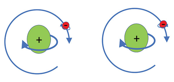
Enter the previous foe of the database architect, the atom. While the atom was busy repealing Moore’s Law, its subatomic particles were busy spinning. The neutrons and protons in the nucleus were rotating, while at the same time the electrons were busy orbiting about the nucleus, while also spinning on their own axes. This is analogous to Earth orbiting around the sun while simultaneously spinning on its axis.
The electrons can spin around their axes clockwise or counterclockwise. Considering there are roughly 7 octillion (7 with 27 zeros after it) atoms in a human, with all the subatomic particles spinning in our bodies, it is amazing we aren’t permanently dizzy. (Note: The subatomic particles aren’t really busy spinning and orbiting, they are really busy giving us probability wave functions and magnetic interactions that would give us results similar to what would happen if they were spinning and orbiting. But if the thought of all the spinning makes you dizzy, trying to comprehend the reality of quantum mechanics will make you positively nauseous.)
Conceptual atoms with nucleus and valence electron with nuclear spin, electron spin and orbital spin. (Image: Microchip Technology)
When microwave radiation at a very specific precise frequency is absorbed by an electron, the direction of spin about the electron axis can be changed. If this happened to Earth, the Sun would suddenly set in the east and rise in the west!
Atomic clocks are machines designed to detect the state of the electron spin, and then change that direction through microwave radiation. The frequency varies depending on the element, the isotope, and the excitation state of the electrons.
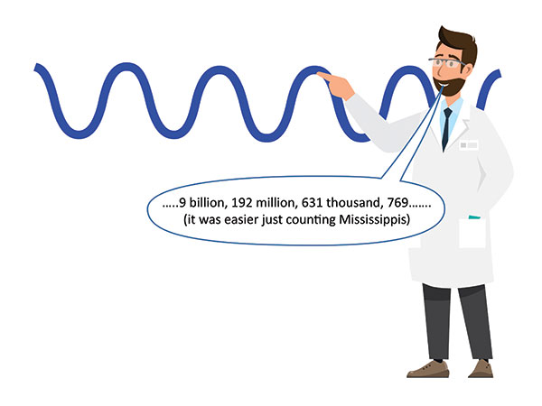
Once the machine determines the frequency, known as the hyperfine transition frequency, the period can be determined as the inverse of the frequency, and the number of periods can be counted to determine the elapsed time. The international definition of the second is 9,192,631,770 periods of the radiation required to induce the hyperfine transition of an electron in the outer orbital shell of a cesium atom.
Atomic clocks are the most stable commercially available clocks in the world. An atomic clock the size of a deck of cards called the chip-scale atomic clock (CSAC) will drift 1 millionth of a second in 24 hours, whereas an atomic clock the size of a refrigerator called a hydrogen maser will only drift 10 trillionths of a second in 24 hours. (Coincidentally, 10 trillionths is also about the ratio of the radius of the hydrogen atom to the height of the sprinters in the 100-meter dash and of the now-unemployed data-center architect in New York.)
With the accuracy provided by these atomic clocks, approximately 500,000 to ~50 billion non-overlapping time-envelopes can be provided for a distributed database running in data centers in Tokyo, London, New York, Timbuktu or anywhere else in the world.
The unit second is defined by counting 9,192,631,770 cycles of the cesium hyperfine transmission radiation frequency. (Image: Microchip Technology)
Time for Distribution
How does time get to all the data centers from these atomic clocks? Universal Coordinated Time (UTC) is a global time distributed by satellites, fiber optic networks, and even the internet. UTC itself is derived from a collection of high precision atomic clocks located in national laboratories and timing stations around the world. Contributors to UTC receive a report that provides the UTC time from these clocks and their individual offset from calculated UTC. The labs and other facilities then transmit the time to the world.
The UTC report is published monthly and tells the national labs their miniscule timing offset from UTC during the previous month. Technically, we don’t know precisely what time it was up until a month after the fact. And to make things worse, extra seconds are periodically added to UTC, called leap seconds, which are inserted due to variations in the Earth’s rotation and our relative position to observable stars. While this aligns Earth to the universe, it causes havoc in data centers and 100-meter dashes.
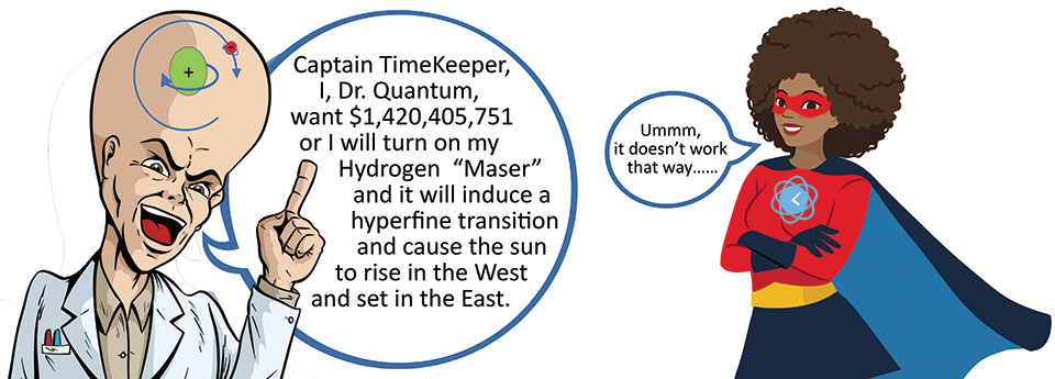
The hyperfine transition frequency produced in a hydrogen maser, 1.420405751 GHz, will cause spin reversal in an electron. (Image: Microchip Technology)
Enter GNSS
Two common methods used by data centers to acquire UTC are via the internet using publicly available NTP time servers and via satellite using GPS or other GNSS networks. While timing through public NTP timeservers over the internet was common during early deployment of distributed databases, inherent performance, traceability and security issues have created the push to move away from this solution.
Even though GPS and other GNSS are typically thought of as positioning and navigation systems, they really are precision timing systems. Position and time at a receiver are determined by the transit time of signals traveling at the speed of light from multiple satellites to the receiver. Ironically, this is another case of a physics principle causing a problem — in this case the speed of light instead of the atom — but also contributing to the solution.
The satellites have their own onboard atomic clocks, which are synchronized to UTC that was transmitted to the satellites from ground stations. Acquiring UTC with this method can provide time uncertainties in the 5-nanosecond range, enabling 100 million time-envelopes per second.
This method is far more reliable and accurate than public NTP servers, and while these signals can be interrupted by such events as solar storms or intentional signal jamming, backup clocks that have been synchronized to the satellite signals when present can be placed in each individual data center to provide the desired uncertainty levels during these interruptions.
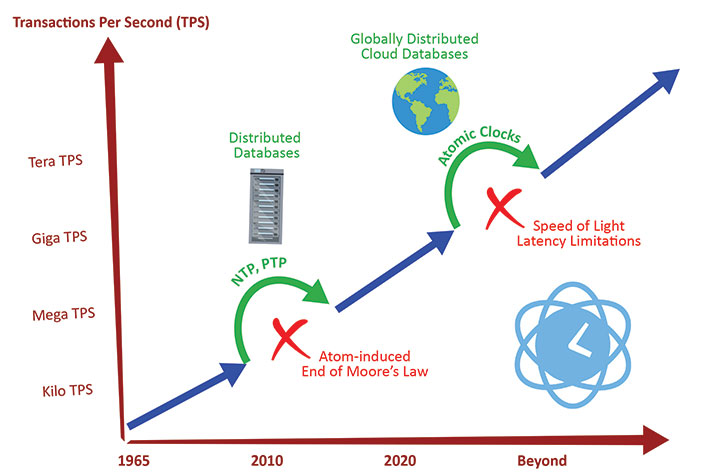
The evolution of database transaction rates and the enabling and disabling technologies. (Image: Microchip Technology)
Next Up: Jumping Electrons
As our quest to acquire, store and transact data in the future continues to grow, novel atomic-clock technologies and time transmission systems with lower uncertainties will be needed. Currently, national timing labs are developing atomic clocks that work on the optical transitions that occur when an electron jumps orbital shells. These offer frequency stabilities to a quintillionth of a Hertz and will eventually be used to redefine the unit second.
Signal transmission through dedicated fiber-optic links or airborne lasers are already yielding improved transmission accuracy. With these continued innovations data, the atom and light will continue their complex love-hate relationship to enable ever larger quantities of data processed at ever increasing rates without consistency issues or causality casualties.
“Seen & Heard” is a monthly feature of GPS World magazine, traveling the world to capture interesting and unusual news stories involving the GNSS/PNT industry.
Photo: Alexey_Seafarer/iStock/Getty Images Plus
HOW BIG IS THAT BEAR?
Monitoring the weight of polar bears — an important health factor — usually means tranquilizing them from the air and lifting them with a tripod attached to a scale. However, technology might provide a non-invasive solution. Various zoos and sanctuaries are testing the accuracy of lidar scanners to measure the weight of polar bears, reports Geo Week News. The scans could be done using drones and mobile mapping equipment and techniques, according to Joel Cusick, a GIS specialist for the National Parks Service.
Photo: PaulFleet/iStock/ Getty Images Plus
SLIP SLIDING AWAY
Researchers used a combination of GNSS and interferometric synthetic aperture radar (InSAR) data from Sentinel-1 satellites to determine subsidence in
99 cities around the world between 2015 and 2020. Subsidence rates in Tianjin, Semarang and Jakarta exceed 30 mm per year. Even in mostly stable cities, areas are sinking faster than sea level is rising, with Istanbul, Lagos, Taipei, Mumbai, Auckland and Tampa sinking faster than 2 mm per year in some areas. Besides climate change, causes include groundwater extraction, mining, reclamation of natural wetlands, infrastructure projects and ecological disturbances. The study is published in Geophysical Research Letters.
Photo: NOAA Fisheries/Raymond Boland
FINDING NEMO
National Oceanic and Atmospheric Administration (NOAA) ocean mapping ship Rainier completed a five-month expedition to the Mariana Islands in September, combining mapping and charting with coral-reef ecosystem surveying. Collection of high-resolution mapping data in near real time improved the effectiveness of the traditional marine science data collection as the combined team mapped 4,000 square nautical miles of seabed and conducted 1,800 SCUBA dives. The data will improve navigation safety through updated NOAA nautical charts and increase understanding of coral reefs through the National Coral Reef Monitoring Program. Besides charts, the seabed mapping data supports marine protected areas, sustainable fisheries, and offshore wind siting — and, in the Marianas, is important for tsunami modeling.
Photo: mikulas1/iStock/Getty Images Plus
GRAVITY DOWN UNDER
An airborne gravity sensor is flying above 80,000 square kilometers of New South Wales (NSW), Australia, collecting data that will improve the accuracy of real-world heights from GNSS positioning to just a few centimeters. Data for the 18-month NSW Gravity Model project will be captured in five stages, starting in Western NSW. The resulting model is expected to enable better resource management, infrastructure planning and natural hazard preparation. It is also a critical building block for developing digital twins, replacing datasets that predate GNSS positioning.
GNSS researchers presented hundreds of papers at the 2022 Institute of Navigation (ION) GNSS+ conference, which took place Sept. 19–23 in Denver, Colorado, and virtually. The following five papers focused on atmospheric effects on GNSS signals. The papers are available at www.ion.org/publications/browse.cfm.
Addressing Scintillation Error
Mitigating the scintillation effect at low latitude is a complex matter: several kinds of experimental data must be collected, realistic models must be developed, and, most importantly, useful real-time indices and alerts must be made available.
The authors introduce a prototype based on a patent owned by SpacEarth Technology to address scintillation error detection and mitigation, supporting precision GNSS-based services at low latitudes in any season and space weather conditions. The patent relates to a method of total electron content (TEC) and scintillation empirical forecasting, in particular short-term forecasting (seconds to minutes). The output of the method is necessary to feed mitigation algorithms aiming at improving accuracy on GNSS precise positioning techniques (RTK, NRTK, and PPP) under ionospheric harsh conditions.
The prototype is designed with a Central Elaborating Facility, which collects the data provided by a network of GNSS monitoring stations detecting scintillation events, and broadcasts foreseen scintillation parameters. Users with a rover mitigation device can apply the parameters from the central facility for scintillation error mitigation.
Vincenzo Romano, INGV and SpacEarth Technology; Claudio Cesaroni, INGV; Luca Spogli, Alessandro Fiorini, INGV and SpacEarth Technology; Marco Fermi, Gter; Lorenzo Benvenuto, Gter and University of Genoa; Tiziano Cosso, Gter; Marcin Grzesiak, SRC/PAS; Joao Francisco Galera Monico, Italo Tsuchiya, UNESP; Gabriel Oliveira, Marcos Guandalini; “Ionospheric Scintillation Mitigation at Low Latitude to Improve Navigation Quality.”
Ring of Fire GUARDIAN
Commonly, natural hazards release energy into the Earth’s atmosphere in the form of acoustic-gravity waves, which propagate up to the ionosphere. The resulting traveling ionospheric disturbances (TIDs) can be detected using GNSS signals, through the computation of the integrated total electron content (TEC) along the lines of sight between GNSS receivers and satellites. The global distribution of ground-based GNSS receivers constantly tracking multiple GNSS constellations (GPS, Galileo, GLONASS, BeiDou, and others) provides excellent spatio-temporal coverage around the world, including in areas of limited coverage by existing warning systems.
The authors present the operational GNSS-based Upper Atmospheric Real-time Disaster Information and Alert Network (GUARDIAN). Based on dual-frequency GNSS data from the Global Differential GPS (GDGPS) network of the Jet Propulsion Laboratory, the GUARDIAN architecture computes slant TEC time series in near real time.
As part of the GDGPS network, 78 stations around the Pacific ring of fire monitor the four GNSS constellations: GPS, Galileo, GLONASS and BeiDou. Cycle slips are corrected and the time series are filtered, both in real time. The resulting data stream is output live to a user-friendly public website, benefitting the general public and the scientific community.
The current GUARDIAN focuses on the Pacific region. However, the architecture can readily be extended to a worldwide coverage.
Léo Martire, S. Krishnamoorthy, L. J. Romans, B. Szilágyi, P. Vergados, A. W. Moore, A. Komjáthy, Y. E. Bar-Sever, A. B. Craddock, NASA Jet Propulsion Laboratory, California Institute of Technology; “GUARDIAN: A Near Real-Time Ionospheric Monitoring System for Natural Hazards Early Warnings.”
Civil Aviation Interference
The authors provide a survey on GNSS receiver architectures with emphasis on new carrier-tracking techniques for mitigating the adverse effect of ionospheric scintillation within the context of civil aviation. The survey is complemented by results gathered from simulations on the impact of ionospheric scintillation in conventional receiver architectures. A review on scintillation mitigation techniques is carried out, covering several “technique families,” highlighting their potential for performance improvement, as well as their shortcomings and challenges in implementation.
A semi-analytical simulation campaign is carried out for different modulations: L1, L5 for GPS, and E1, E5a for Galileo. Here, the performance of a standard receiver tracking a set of GPS and Galileo satellites affected by ionospheric scintillation is analyzed to pinpoint existing vulnerabilities to this effect.
The simulation results show that ionospheric scintillations are responsible for large variations in carrier-to-noise ratio, which in turn can be responsible for losses of lock and large phase variations, increasing phase RMSE and in some cases leading to cycle slips of the phase estimation. Thus, the adopted solution must be robust to signal power fluctuations and the occurrence of cycle slips and able to maintain phase lock.
António Negrinho, GMV-PT Pedro Boto, GMV-PT Marta Cueto, GMV-ES Mikael Mabilleau, EUSPA Claudia Paparini, EUSPA Ettore Canestri, EUSPA; “Survey on Signal Processing Techniques for GNSS Ionospheric Scintillation Mitigation.”
Tonga Eruption Data Analyzed
Extreme natural disasters, such as volcanic eruptions, can create visible pressure waves in the atmosphere and trigger observable ionospheric wave responses that can travel hundreds of kilometers in the ionosphere. The acoustic and gravity waves generated can cause ionospheric TEC perturbations and variations. The TEC determines the GNSS ionospheric delay and can cause significant positioning errors, which may affect the performance of GNSS-based applications.
The researchers processed GNSS data collected from the Hong Kong Satellite Positioning Reference Station Network to analyze the ionospheric activity and positioning performance responding to the Tonga volcanic eruption on Jan. 15, 2022. To detect and repair cycle-slip jumps, the researchers applied theTEC rate and Melbourne Wubbena Wide Lane (MWWL) linear combinations. A Savitzky-Golay low-pass filter with a 30s window was used to improve the TEC accuracy.
The team investigated the changes in TEC, Rate of TEC index (ROTI) and positioning errors in the eastward, northward and upward directions after the anomalous ionospheric propagation to Hong Kong between 11:30 and 14:30. The team found the ionospheric anomaly could generate large changes in the three parameters, with peaks up to three times the calm period. Their prompt research contributes to a better understanding of the coupling of extreme ionospheric activities and dynamics caused by volcanic eruptions.
Xiaojia Chang, Kai Guo, Zhipeng Wang, Kun Fang, Hongxia Wang, Beihang University; Hailong Chen, China Academy of Aerospace Electronics Technology; “Ionospheric Anomaly and GNSS Positioning Responses to the January 2022 Tonga Volcanic Eruption.”
Toolbox for Monitor Network
The MONITORtoolbox is a set of Python-coded software tools to perform automatized large-scale processing of data from the Monitor network of the European Space Agency (ESA). The Monitor network aims to continuously monitor ionospheric scintillation events from multiple ground stations strategically located around the globe. It accommodates a repository with a large number of GNSS measurements containing scintillation events for users to analyze scintillation data or for research purposes.
This paper shows the potential of the MONITORtoolbox for providing access to a large amount of data that otherwise, without a systematic processing, becomes practically useless. The software developed implements the means to collect data and store it in a local database for quick offline access. It detects the presence of scintillation events based on certain conditions and criteria defined by the user and identifies its properties in terms of duration, time of occurrence, intensity and satellite location. It implements the tools to compute relevant statistics, providing insights on ionospheric scintillation phenomena.
Sergi Locubiche-Serra, Alejandro Pérez-Conesa, Diego Fraile-Parra, Gonzalo Seco-Granados, José A. López-Salcedo, Universitat Autònoma de Barcelona, IEEC-CERES; Juan M. Parro-Jiménez, Raúl Orús-Pérez, ESTEC, European Space Agency; “MONITORtoolbox — Software Tool for the Analysis of Ionospheric Scintillation Data from the ESA Monitor Network.”
Achieving PNT resilience for critical infrastructure applications
GNSS are magic. They are. One dictionary defines magic as “a power that allows people (such as witches and wizards) to do impossible things by saying special words or performing special actions.” By this definition, we have all become witches and wizards, doing what previous generations would have deemed impossible.
This magic, however, can be affected by external forces that render it useless at best and, at worst, dangerous. Warnings about GNSS positioning, navigation and timing (PNT) service vulnerabilities have been raised for 25+ years. Numerous organizations have warned of the potential safety, security and economic impacts of GNSS interference. Still, like modern-day Cassandras, their warnings have been ignored, and sole use of PNT services that rely on space-based signals continues to expand.
“Magic services” are addictive and cannot be ignored. Yet, it is well past the time to merely admire the problem of GNSS interference — benefitting from magical GNSS services while ignoring existing and emerging threats and challenges. It is time to draw a line and implement resilient, complementary PNT solutions to support all critical infrastructure sectors and applications in the event of any GNSS disruption, due to jamming or spoofing or systemic causes. “Magic” is magical when it works. When it does not, first and foremost, it should “do no harm.”
Threats, Challenges and Needs
Presidential Policy Directive (PPD) 21, Critical Infrastructure Security and Resilience,issued in 2013, defines resilience as “the ability to prepare for and adapt to changing conditions and withstand and recover rapidly from disruptions.” It also notes that “resilience includes the ability to withstand and recover from deliberate attacks, accidents, or naturally occurring threats or incidents.”
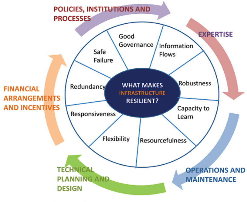
In 2016, the UK Department of International Development noted that “Resilience covers both ‘physical and societal systems” through four “R” principles: robustness, redundancy, resourcefulness and rapidity (see Figure 1).
Figure 1. Infrastructure resilience properties. (Image: UK Department of International Development)
More recently, Andy Proctor (RethinkPNT) pointed out that “A resilient PNT system protects its critical capabilities (assets) from harm by using protective resilience techniques to passively resist or actively detect threats, respond to them, and recover from the harm they cause.”
Policies, processes, financial arrangements and incentives are also crucial to achieving resilience — and that has been, and remains, the problem. Lacking the emergence of strong leadership from our institutions, the ability to achieve actual resilience will continue to falter and admiration of the problem will continue.
Developing a resilient PNT system is always a balance of technical complexity and non-technical aspects, for example, costs. The key consideration for users must be the required performance metrics they need for their use-case(s) to ensure their resilience — including accuracy, availability, integrity, continuity and coverage. The one least understood and many times omitted is integrity — the level of trust a user/use-case needs to safely and securely use the PNT services. The ability to trust PNT services must always be a consideration for critical infrastructure applications.
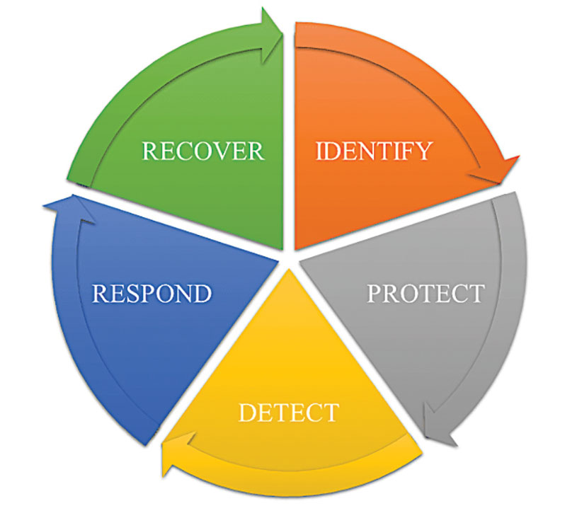
Unfortunately, many users of critical infrastructure PNT do not know some of the PNT metrics they need to ensure safety and security. More troubling, there is no guidance as to what constitutes “significant economic impact” (see PPD 21) or acceptable economic loss — and over what period or range of use cases. This understanding will require analysis of their design, development and operational experiences, and working with PNT systems engineers to first derive these metrics and then drive the continuous improvements (see Figure 2) needed to achieve and retain truly complementary PNT capabilities. Without clear metrics and guidance, one cannot claim that any solution will meet any “required level of resilience.”
Figure 2. Resilient PNT lifecycle.
Supporting PNT Users
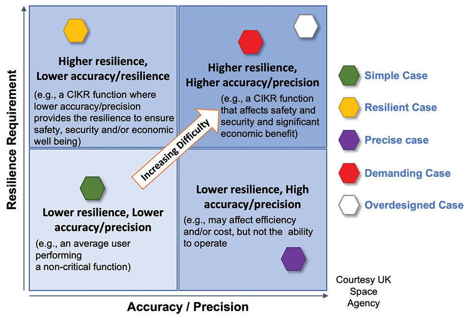
As with all systems engineering (SE) activities, PNT system resilience begins with identifying and documenting user needs based on their specific user stories/use cases. Figure 3 depicts different aspects of resilience that can be sought, depending on the unique use-case “demands.”
Figure 3. Resilience aspects. (Photo: UK Space Agency)
While the resilience needs of different use cases will differ, for any specific use case, a given “PNT solution” will either achieve the required/threshold level of resilience (based on the operational environment) or it will not. Some use cases may also require fail-safe or fail-soft capability and the ability to recover to known, trusted and usable states. Shouldn’t many, if not all critical sector use cases require this?
Equally important is the identification of risks and threats, as they are critical to understanding the challenges that the system must face while continuing to provide the necessary P, N and/or T service performance. It is also key to understand and document the system architecture and environment in which it must perform. With knowledge of a user’s needs, the threats, hazards and challenges they face, and the system architecture, the SE process can develop an understanding of the “gaps” that exist and of the levels of risk they impose on a critical infrastructure system’s functional, physical and operational performance. Understanding this, essential use-appropriate mitigations can be identified, or if need be, developed, and a resilient, solution-agnostic PNT requirement document created.
The Way Forward
The Critical Infrastructure Resilience Institute (CIRI), a U.S. Department of Homeland Security Center of Excellence, notes that “critical infrastructure systems are facing a myriad of challenges. Solutions must address the cyber, physical and human dimensions.” They keyed into four areas where critical infrastructure resilience activities should be directed: building the business case, information policy and regulation, developing new tools and technologies, fostering and educating the workforce.
These include the recognition that “policy and regulation have a powerful impact on market forces.” While the fact that “most U.S. infrastructure is owned and operated by the private sector” is a challenge, it should not be an excuse.
We must start immediately to re-establish strong SE practices, policies, and principles to help critical users understand their needs and determine the metrics required to ensure safety and “preclude significant economic impact.” Only then can we understand from a national perspective, the needed safety and security metrics and what constitutes significant economic impact, and then establish categories of solution-agnostic requirements. Lacking these clear resilience targets, detailed planning, and required resource commitments, the growing threats of PNT vulnerability will continue only to be admired, rather than be mitigated. Hope is not a strategy, but this systems engineer hopes that it does not take a truly catastrophic event to finally prompt much needed and long overdue actions.
Mitch Narins is the principal consultant/owner of Strategic Synergies LLC, a consultancy he formed following more than 40 years of U.S. government service. He is a Fellow of the Royal Institute of Navigation, a aenior member of the Institute of Electrical and Electronic Engineers, a member of the Institute of Navigation and head of its Washington, D.C., section, and a member of RTCA, RTCM, IEEE and SAE Standards Committees.
Multinational technology firm GMV has signed an agreement with Lockheed Martin Corporation to develop the processing and control centers for the Southern Positioning Augmentation Network system (SouthPAN). Lockheed is contracted to establish SouthPAN.
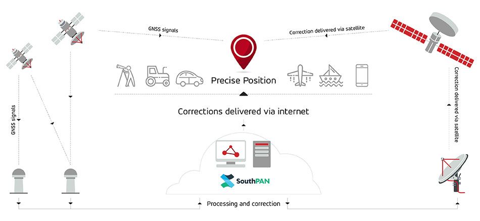
The project is a joint initiative of the Australian and New Zealand governments to provide a satellite-based augmentation system (SBAS) for navigation and precise point positioning (PPP) services. GMV will also be responsible for monitoring both of these services in the region and for ensuring compliance with the committed performance levels.
SBAS and PPP systems have applications in industries as diverse as agriculture and road, air, maritime and rail transportation, as well as in the field of geomatics. SouthPAN is expected to accelerate development of applications in these areas.
SouthPAN is also the first system with these characteristics available in the Southern Hemisphere. With this new program, Australia and New Zealand will be contributing to improved global coverage and interoperability for services of this type, joining the list of countries and regions that already have their own SBAS system: the United States (WAAS), Europe (EGNOS), India (GAGAN) and Japan (MSAS).
On Sept. 26, two weeks after the agreement was signed, the first services were provided by activating transmission of the system’s first signals. This was a significant milestone, because SouthPAN is the first project where an industry consortium provides an SBAS as a service, rather than as a turnkey system.
Image: SouthPAN
GMV’s role
GMV will be responsible for developing two key subsystems for SouthPAN: the Corrections Processing Facility and the Ground Control Center. The company will also be responsible for monitoring the system and ensuring it complies with the committed performance levels.
GMV also will provide support for the system’s operation and maintenance.
Corrections Processing Facility. The facility generates correction messages for signals transmitted by GPS and Galileo, improving precision for users by improving accuracy to as little as 10 centimeters.
The facility also detects malfunctions in the satellites and generates warnings for users. This will allow use of SouthPAN by civilian aircraft as a navigation system during various flight operations, including precision approaches to runways for landing.
Safety-of-life services such as these will be available in 2028.
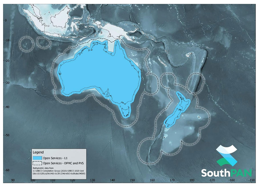
SouthPAN early Open Services coverage. OS-L1 covers mainland Australia and New Zealand. OS-DFMC and OS-PVS cover Exclusive Economic Zones in both countries. (Image: Geosciences Australia)
Ground Control Center. The control center remains in operation 24 hours a day seven days a week, and will perform all the functions needed to monitor and control the system. It will also provide information to users about the system’s operation and availability of services.
In Australia, SouthPAN development, entry into service and operation are being supervised by Geoscience Australia in collaboration with Toitū Te Whenua Land Information New Zealand.
In 2020, the two agencies signed the Australia New Zealand Science, Research and Innovation Cooperation Agreement (ANZSRICA). Over the next 20 years, the Australian government will be contributing 1.4 billion Australian dollars to the SouthPAN project.
Innovative chip offers multiple ultra-low power connectivity options and low-power processing for internet of things (IoT) market
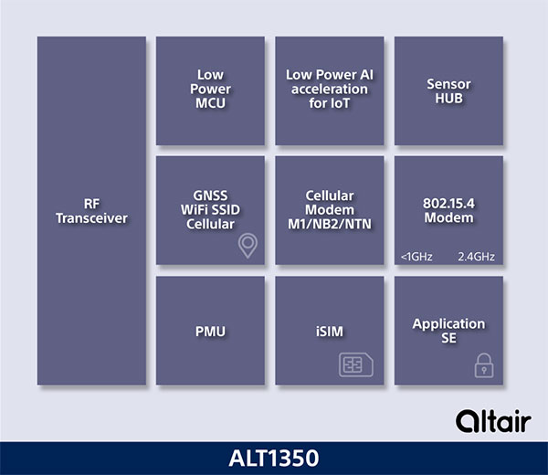
Sony Semiconductor Israel has launched the ALT1350 for the global market. The ALT1350 is a cellular LTE-M/NB-IoT chipset designed to enable additional low-power wide-area (LPWA) communication protocols, as well as GNSS, in a single chipset.
The ALT1350 incorporates a sensor hub to collect data from the sensors while maintaining ultra-low power consumption. It also provides cellular and Wi-Fi-based positioning and is tightly integrated to provide power-optimized concurrent LTE and GNSS to accommodate various tracking applications, which can be demanding with a single chip.
“The market demand for this multiprotocol, ultra-low power IoT chipset is intensifying, and Sony’s ALT1350 chipset meets that demand,” said Nohik Semel, CEO at Sony Semiconductor Israel. “This is the game changer we’ve been waiting for, which will enable IoT deployments, utilizing universal connectivity on edge processing and multiple location technologies.”
Diagram: Sony
The ALT1350 is an advanced cellular IoT solution, with architecture that resolves IoT service provider’s power-consumption concerns. Its optimized standby mode (eDRX) reduces power consumption by 80% when compared to the current generation and by 85% when using it to send short messages.
Overall improvements in the system’s power consumption will enable four times longer battery life for a typical device, enabling additional functionalities and use cases with smaller batteries.
The ALT1350’s sub-GHz and 2.4 GHz integrated transceiver enables hybrid connectivity for smart meters, smart cities, trackers and other devices. This enhances coverage, reduces costs and further decreases power consumption using IEEE 802.15.4-based protocols such as Wi-Sun, U-Bus Air and wM-Bus, in additional point-to-point and mesh technologies.
The chipset is designed to support the wide-ranging market needs of utilities, vehicle, tracking devices, smart cities, connected health and other verticals. Device manufacturers across all verticals can take advantage of its low power consumption, long-lasting battery life, mature Release 15 LTE-M/NB-IoT software stack, and future compatibility with 3GPP release 17.
All these guarantee longevity and ensure the ALT1350 will operate with 5G networks. It contains an additional LPWA radio transceiver with targeting operation in <1 GHz and 2.4 ISM bands for universal connectivity options.
The chipset provides advanced on-the-edge low power processing capabilities, ranging from data collection, low power AI/ML processing of the data, and MCU to enable IOT applications on the chip.
The device is now sampling to lead customers and will become commercially available in 2023. The ALT1350 also includes a secure element for application usage and integrated SIM designed for PP-0117 to meet GSMA requirements.
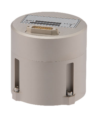
The IMU-FI-200C FOG IMUs are a fully integrated inertial measurement solution that combines the latest closed-loop FOG and MEMS sensors technologies
Inertial Labs has released the IMU-FI-200C high-performance fiber-optic gyroscope (FOG) inertial measurement unit (IMU), a compact, self-contained strapdown, advanced tactical-grade IMU that measures linear accelerations and angular rates with three-axis tactical-grade, closed-loop FOG and three-axis high-precision MEMS accelerometers in motionless and high-dynamic applications.
The IMU-FI-200C FOG IMUs are a fully integrated inertial measurement solution that combines the latest closed-loop FOG and MEMS sensors technologies. It is designed for a wide range of higher order integrated system applications, such as
antenna and line-of-sight stabilization systems
passenger train acceleration/deceleration and jerking systems
motion reference units
motion control sensors
gimbals
electro optical components/infrared
platform orientation and stabilization.
Fully calibrated, temperature-compensated and mathematically aligned to an orthogonal coordinate system, the IMU contains gyroscopes with an accuracy of up to 0.5 deg/hr and accelerometers with a bias repeatability of less than 2-mg over their operational range, very low noise and high reliability.
The IMU-FI-200C FOG IMUs have been thoroughly tested to perform in significant variations in temperature, high vibration and shock, and is designed to be used in air, marine and land environments.
“New technology creates new opportunities, and the new IMU-FI-200C represents the innovative approach we take every day at Inertial Labs,” said Jamie Marraccini, president & CEO of Inertial Labs. “The high performance and flexibility to integrate into different systems and applications is what we have striven to provide to our customers with this new release.”
Registration is now open for the jointly sponsored Position Location and Navigation Symposium (PLANS) taking place April 24-27. PLANS is a biennial technical conference that occurs in the spring of odd-numbered years to provide an international forum to share the latest advances in navigation technology. The conference is sponsored by the IEEE’s Aerospace and Electronics Systems Society (AESS) and the Institute of Navigation (ION).
The PLANS conference takes place over four days, with the first day for hosting tutorials and three days dedicated to technical sessions.
The tutorials aim to provide attendees with the opportunity to learn about navigation technology from industry experts. A variety of tutorials are offered to serve the needs of both newcomers and those well versed in the field of navigation. This year’s tutorials will include a range of navigation subjects from core navigation fundamentals to in-depth classes about the latest technologies.
Technical sessions are offered over a three-day period, with four sessions running simultaneously each morning and afternoon. At the technical sessions scientists, researchers, and engineers from around the world present their latest work in the field of PNT. Technical session topics will include inertial sensing and technology; GNSS; integrated, collaborative and opportunistic navigation; and applications to automated, semi-autonomous and fully-autonomous systems.
To view the PLANS 2023 technical program and register for the event, visit ion.org/plans.