2,300-acre Shell Deer Park Refinery provides complex testbed for aerial inspections and incident response
Photo: SimonSkafar/E+/Getty Images
DJI is partnering with Shell Oil Company to create, test and deploy DJI drone technology at its Deer Park Manufacturing Complex to improve efficiency and worker safety during industrial inspections and emergency incident response.
The Shell Deer Park drone team adopted DJI drones in 2016 to reduce the need to work at height while improving safety and cutting the cost of inspections in the process. As a Solution Development Partner, Shell will work with DJI to develop and test advanced drone solutions, like the DJI Matrice 300 RTK, that allow workers to automate required inspections of critical infrastructure like flare tips and floating roof tanks whose condition and activity are difficult to assess from ground level.
“As one of the world’s largest energy companies, Shell has provided us with valuable insight into the unique challenges of conducting aerial inspections at one of its largest facilities where infrastructure exceeds the height of 250 feet off the ground,” said Cynthia Huang, until recently the director of business development at DJI. “Through our collaboration, DJI will receive valuable first-hand insight into the complexities of deploying drone technology at a world-class refinery, and co-develop new product features like AI Spot-Check that will allow Shell and other innovative energy companies to use drones to safely and easily conduct required inspections of critical infrastructure.”
“Shell Deer Park is excited to become a Solution Development Partner with DJI as we continue to adopt drone technology,” said Shell Deer Park’s Chief Drone Pilot John McClain. “Through this partnership, Shell Deer Park will have access to some of the most advanced drone technology from DJI to help elevate workplace safety and improve efficiency across our operations in the world’s largest industry.”
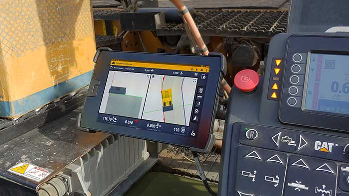
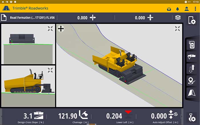
According to the company, Trimble Roadworks is an accurate, automatic 3D screen control system that can improve paving productivity and rideability by directly referencing the design rather than a surface or stringline to minimize asphalt usage, reduce waste and overruns, and finish projects on time and under budget.
The Android-based application runs on the 10-inch touch screen Trimble TD520 display. Operators can personalize the interface to match their workflows, and configurable views make it easier to see the right perspective for maximum productivity, the company said.
The software uses components from Trimble Earthworks, which Trimble says increases the portability of the hardware. Users also can download other third-party applications that provide the operator with additional useful tools inside the cab.
Screenshot: Trimble
“Trimble Roadworks is easy to learn and more accessible for many different types of contractors because it leverages the intuitive Trimble machine control interface and applies it to asphalt pavers,” said Kevin Garcia, general manager for Trimble Civil Construction Specialty Solutions. “This platform also makes it possible to include Trimble’s industry-leading paving technology as part of a connected site ecosystem of solutions, which is valuable for complex infrastructure projects.”
In addition, using a Trimble SNM941 Connected Site Gateway, Trimble Roadworks allows the transfer of 3D designs from the office to the machine via the cloud so that the operator is always using the latest design.
Trimble Roadworks 3D Paving Control Platform for Asphalt Pavers is now available globally through the worldwide SITECH distribution channel.
integration with inertial measurement units (IMUs) and other sensors
positioning using cell phones and other consumer devices
any other areas or challenges they find particularly significant.
All four respondents in this issue, like to those in the January issue, report that they are making full use of the new GNSS signals available, taking hardware and software measures to counter jamming and spoofing, and integrating IMUs and other sensors with their GNSS receivers to help achieve continuous navigation and positioning in obstructed environments. In addition, they are continuing to develop mass-market applications, because high-precision positioning is becoming increasingly important for cellphones and wearable devices. For a fuller review of these trends, see my introduction to the first installment.
Notably, two of the companies featured in this issue, ComNav Technology and Unicore, are Chinese.
With Chad Pillsbury, Senior Director, Raytheon Intelligence & Space’s Resilient Navigation and Reconnaissance Solutions
Utilizing Galileo and BeiDou
Integration and fusion of multiple space position services is a key element in achieving assured positioning, navigation and timing (PNT). A combination of commercial and military-code navigation signals, when coupled with evolving sensors, provide more resilient methods of navigation and enable new concepts of operations related to PNT. Over the next two years, RI&S will customize these concepts of operation (CONOPS) for our United States and international allies to harness the power of fusion in resilience.
Dealing with jamming and spoofing
As threats to GPS continue to evolve and mature, RI&S continues to develop alternative navigation solutions, as well as GPS-capable receivers and antennas, aimed at defending against a variety of spoofing and jamming technologies. Our latest anti-jam, anti-spoof and high-precision solutions leverage a recent technology breakthrough that lowers size, weight, power and cost while boosting performance in the new M-code and alternative navigation applications.
Integration with IMUs and other sensors
IMUs are the cornerstone of high-performance navigation systems and will continue to be in the future. Recent innovations allow some systems to become more IMU agnostic, or even to consider microelectromechanical systems (MEMS) IMUs depending on performance, which can allow the customer greater flexibility and a more open architecture.
Positioning with consumer devices
RI&S sees 5G as a game-changing technology, with a lot of possibilities in the assured navigation market. We also look to cellphones as a great area of interest — especially for exploring unforeseen signals, considering human international models, and learning how the next generation of GPS users expect to see PNT information displayed.
Other significant challenges and opportunities
The future of GPS lies in a system-of-systems approach. Using time as a backbone, navigation systems can securely share time, data, position and intent across the network. Broadly, this approach can be used in civil, commercial and military environments. RI&S is fully focused on developing capabilities to achieve this ideal state.
Unicore Communications
With Gao Jingbo, Marketing Director
Utilizing Galileo and BeiDou
Most of Unicore’s high-precision products support all constellations and multiple frequencies. The new BeiDou 3 provides precise point positioning (PPP) service from three geostationary satellites via the B2b frequency, while Galileo offers up to five frequencies — E1, E5a, E5b, E5 AltBOC and E6. End users will benefit from improved PNT availability, reliability and continuity as access to those signals greatly reduces multipath effects and allows faster PPP convergence times.
Dealing with jamming and spoofing
To effectively deal with signal jamming and spoofing, it is important to know their sources. GNSS receivers also are susceptible to electronic interference and vulnerable to complex electromagnetic environments. Unicore integrates GNSS RF, baseband and algorithms into a single GNSS system-on-chip (SoC) that mitigates external interference. Joint time-frequency domain interference mitigation technology also is adopted in chip design.
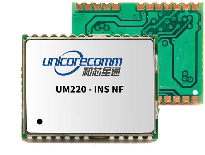
Photo: Unicore Communications
Integration with IMUs and other sensors
Demand for seamless, accurate indoor-outdoor location is increasing. The integration of GNSS with IMUs, lidar, cameras and other sensors helps achieve continuous navigation and positioning in obstructed environments such as urban canyons and tunnels. Unicore offers receivers integrated with both high-end IMUs and affordable MEMS-based devices. Dual-frequency GNSS plus MEMS provides an ideal positioning solution for automotive applications.
Positioning with consumer devices
High-precision positioning is becoming increasingly important for cellphones and wearable devices, and multi-scenario adaptation is necessary. Instead of integrating standalone GNSS chips with smartphone processors, cellphone manufacturers prefer to cooperate with GNSS manufacturers through GNSS intellectual property (IP) licensing. To ensure high-precision service, better cellphone antennas are also important.
Other significant challenges and opportunities
We strive to deliver reliable, timely and smart positioning for anything, anywhere, anytime. Next-generation GNSS location products and services should be more end-user-friendly. The hardware interface will be more universal, flexible, configurable and adaptable with different algorithms for a diverse range of applications.
Teleorbit
With Daniel Seybold, CEO
Utilizing Galileo and BeiDou
Our GOOSE receiver has been able to use Galileo since its beginning and BeiDou since the forth quarter of 2020. Signals from both can be used individually or with other signals (GPS, Galileo, GLONASS and BeiDou, plus SBAS).
Dealing with jamming and spoofing
Open Service Navigation Message Authentication (OSNMA) is now implemented on the GOOSE, which helps mitigate spoofing attacks. GOOSE’s recording function enables users to record simulated jamming/spoofing attacks, and then analyze the behavior of the GOOSE and the received signals. We are developing various GNSS antenna arrays for nulling and beamforming, as well as a left- and right-hand circular polarized (LHCP/RHCP) antenna with GOOSE adaption for signal processing.
Signal conditioning on the GOOSE platform is based on a high-rate discrete Fourier transform (DFT)-based data manipulator algorithm, known as an HDDM algorithm, that fulfills multiple roles. The HDDM algorithm removes a wide range of interference signals, equalizes the spectrum, or restructures the spectrum.
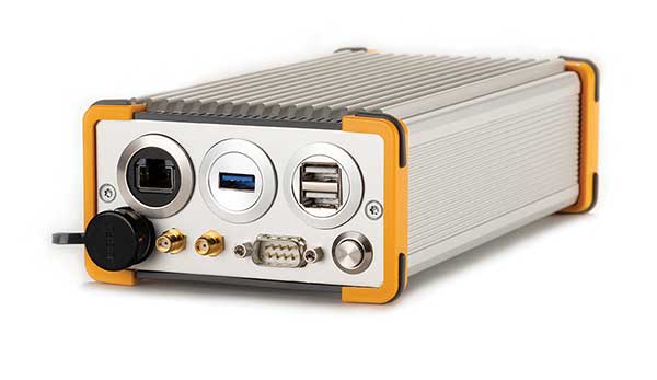
Image: Teleorbit
Integration with IMUs and other sensors
We offer a GNSS antenna with an integrated IMU. Thanks to its open software interface, fusing IMU or other sensor data with GNSS data is easily done with GOOSE. Vector tracking, deep coupling and other sensor fusions (for example, 5G) are on the GOOSE roadmap.
Positioning with consumer devices
Our ongoing AMELIE project will study advanced techniques for the miniaturization and radiation enhancement of GNSS mass-market antennas to be applied in the design, manufacturing and testing of a multi-frequency, low-cost, high-gain dual circularly polarized antenna for the next generation of consumer devices. In 2021, we will build the following antenna demonstrators: single-frequency (L1/E1), dual-frequency (L1/G1/E1, L5/E5a/E5b) and multi-frequency (L1/G1/E1, L5/E5a/E5b, L2, E6).
Other significant challenges and opportunities
GOOSE can track the Galileo E5AltBOC (wideband) signal, which provides code-range variances below a few decimeters. This offers a significant increase in the accuracy of code measurements in terms of reduced noise and mitigation of multipath effects, compared to conventional signals. GOOSE will provide two different approaches for robust tracking: vector tracking for dealing with challenging environments where multipath occurs or buildings block signals, and adaptive tracking to allow the receiver to acclimate to its surroundings by adapting the bandwidth in the loop depending on movement, such as high dynamics.
ComNav Technology
With Min Xu, Director of GNSS Technology R&D Department
Utilizing Galileo and BeiDou
We keep up with the development of GNSS. Our new K8 series of high-precision GNSS modules support the recently completed BDS-3 and Galileo constellations concurrently, significantly improving positioning accuracy especially when signals are partially obstructed. Despite their complex design, the size of K8 modules decreased by almost 36% from their precursors and power consumption dropped to 1.0W, making them easier to integrate.
Dealing with jamming and spoofing
We have developed algorithms to eliminate specific forms of jamming and spoofing, with a focus on narrowband interference. The newly released Quantum III SoC chip — integrated with wideband signal-receiving technology, wideband and narrowband anti-interference technology, and anti-continuous wave interference technology — can provide high-quality observation information in a complex electromagnetic environment.
Photo: ComNav Technology
Integration with IMUs and other sensors
There is an increasing need to add IMUs to supplement obstructed GNSS signals. Empowered by a high-precision IMU, our N5 receiver supports tilt survey with accuracy of less than 2.5 cm. Users can survey without a centering bubble as its calibration-free tilt compensation protects it from magnetic disturbances. We are also focusing on image sensors, such as cameras and radars, to make data collection more flexible and reliable.
Positioning with consumer devices
Our high-precision products are mainly used in professional fields such as land surveying, deformation monitoring, and UAVs. We are continuing to explore GNSS products for consumer markets, which are sensitive to power consumption and cost. The upcoming M10 GNSS is a compact and portable receiver for mass-market applications, such as person or vehicle tracking and fleet management.
Other significant challenges and opportunities
GNSS technology can be widely applied in agriculture, transportation and infrastructure construction. We developed the AG360/AG360 Pro Agricultural Automatic Driving system, which drives autonomously without damaging crops. We collaborated with China Mobile to build more than 2,000 CORS stations to provide high-precision positioning services in support of smart-city construction, IoT and location-based services.
Alliance membership has tripled in past 13 months as the organization grows advocacy for ever-increasing importance of GPS technologies to the global economy.
L3Harris Technologies, a global aerospace and defense technology innovator, joins a core of companies committed to furthering GPS innovation, creativity and entrepreneurship.
As the newest member, L3Harris Technologies will work with GPSIA to promote the modernization of GPS and its impact on military operations, economic growth and technological innovation.
J. David Grossman
“With the addition of L3Harris, the alliance welcomes a company recognized globally for developing and advancing innovative uses of GPS to protect our nation’s national security,” said GPSIA Executive Director J. David Grossman. “Having now tripled membership over the last 13 months, GPSIA is in a position of strength to continue leading advocacy for the promotion, protection and enhancement of GPS, both in the U.S. and around the globe. L3Harris Technologies is an integral part of the deployment of next-generation GPS III satellites and we look forward to working with them to ensure this technology remains the gold standard for delivering positioning, navigation and timing functions to our military as well as a wide range of other sectors, including transportation, agriculture, electricity and finance.”
L3Harris Technologies has played an integral part in the story of GPS, as it has provided navigation technology for every U.S. GPS satellite ever launched. L3Harris Technologies is developing 10 GPS III satellite navigation payloads for the U.S. Air Force’s GPS III satellite program, four of which are already operational.
The company will also provide navigation payloads with fully digital Mission Data Units (MDU) for the U.S. Air Force’s GPS III Follow-On, known as GPS IIIF, satellites. The MDU will provide even more powerful signals and ensure flawless atomic clock operations.
“GPS technology is an important part of the modern world and critical for the warfighter,” said Joseph Rolli, L3Harris Technologies Positioning, Navigation and Timing.
“With more than 40 years of experience developing GPS technologies, L3Harris aims to continue to improve the system with a more powerful, reliable, and flexible signal. We look forward to joining GPSIA and its other industry leading members as we advocate for continued support of this incredible system,” Rolli said.
NIST’s new cybersecurity profile is designed to help mitigate risks to systems that use PNT data, including finance, transportation, energy and other critical infrastructure. While its scope does not include ground- or space-based PNT source signal generators and providers (such as satellites), the profile still covers a wide swath of technologies. (Image: B. Hayes/NIST)
The National Institute of Standards and Technology (NIST) has drafted guidelines for applying its Cybersecurity Framework to critical technologies such as GPS that use positioning, navigation and timing (PNT) data. Part of a larger NIST effort to safeguard systems that rely on PNT data, these cybersecurity guidelines accompany NIST efforts to provide and test a resilient timekeeping signal that is independent of GPS.
Formally titled the “Cybersecurity Profile for the Responsible Use of Positioning, Navigation and Timing (PNT) Services (NISTIR 8323),” the new guidelines are designed to help mitigate cybersecurity risks that endanger systems important to national and economic security, including those that underpin modern finance, transportation, energy and additional economic sectors.
The draft profile is part of NIST’s response to the Feb. 12, 2020, Executive Order on PNT. In early 2020, NIST sought public input regarding the general use of PNT data. The PNT profile will join the growing list of profiles created to help apply the NIST Cybersecurity Framework to particular economic sectors, such as manufacturing, the power grid and the maritime industry. The scope of the profile includes any system, network or other asset that uses PNT services, including systems that receive and rebroadcast PNT data.
While its scope does not include ground- or space-based source PNT signal generators and providers (such as satellites), the profile still covers a wide swath of technologies. Partly for this reason, NIST’s Jim McCarthy said that it is intended to be a foundational set of guidelines that PNT users can customize.
“The profile is meant to help a broad set of users address their cybersecurity needs,” said McCarthy, one of the draft’s authors. “Rather than focus on a single economic sector, we designed it to apply to all users of PNT. Agencies and companies can tailor it to their needs based on their particular cybersecurity risk and other sector-specific factors.”
As directed by the Executive Order, the profile can help organizations accomplish four tasks:
identify systems that use PNT data, and/or that propagate this data based on a source signal
identify PNT data sources, such as a GPS signal
detect disturbance to and manipulation of systems that use PNT services
manage the risks that come with responsible use of these PNT services
“Our premise is that there are organizations that may not realize they are using PNT data, or know how they are using it,” McCarthy said. “Part of our goal is to help them make these connections so they can protect their operations more effectively.”
The Executive Order also delegates to the Department of Commerce the critical task of providing a source of Coordinated Universal Time (UTC) that is independent of GPS. To this end, NIST also recently conducted initial tests of a special calibration service for companies, utilities or other organizations that wish to receive NIST’s version of the global time standard, UTC(NIST), through commercial fiber-optic cable.
The service aims to provide a time reference directly traceable to UTC(NIST) with an accuracy of 1 microsecond — good enough for telecom networks, the power grid and financial markets, and thereby boosting the resilience of accurate time distribution and the infrastructure sectors and subsectors that use timing services.
The initial link is a collaboration between NIST and OPNT, a commercial time-service provider based in Amsterdam, the Netherlands. While the work was led by researchers at NIST’s Boulder, Colorado, campus, the dedicated optical fiber connects the reference time scale at NIST headquarters in Gaithersburg, Maryland, to a facility in McLean, Virginia, that will ultimately serve as the hub for East Coast distribution of timing data.
OPNT has extended the initial fiber link to Atlanta, Georgia, about 800 kilometers from McLean. Preliminary data suggest that this link will be able to support the requirements of the Executive Order.
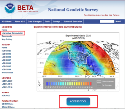
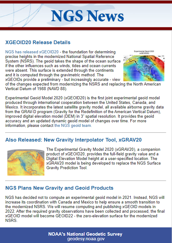
My last column highlighted an ArcGIS web application that incorporates various datasets and data layers to assist surveyors planning vertical control surveys. On Jan, 29, the National Geodetic Survey (NGS) released the latest experimental geoid model, xGeoid20, and a new gravity interpolation tool (see box below, “NGS Releases Annual e& Gravity Interpolation Tools”).
This newsletter will highlight some attributes of these two new products. First, why am I writing about another experimental geoid model. I discussed xGeoid18 in my December 2018 column and xGeoid16 in my June 2017 column. What’s important here is that this will be the last experimental geoid model until 2022, and the dynamic geoid model has also been updated this year in the form of xDGEOID20.
xDGEOID20 is produced by NGS within the Geoid Monitoring Sƒervice (GeMS) and is part of the new NAPGD2022. Therefore, users only have a few more years to understand the differences between the hybrid geoid model that is being used today to estimate GNSS-derived orthometric heights and the gravimetric geoid model which will be used to estimate North American-Pacific Geopotential Datum of 2022 (NAPGD2022) GNSS-derived orthometric heights.
NGS also announced a new gravity tool, denoted as “The Experimental Gravity Model 2020 (xGRAV20).” xGRAV20 is designed to provide a full-field gravity value and a digital elevation model height at a-specified location. The xGRAV20 model will be important to users that are computing leveling-derived orthometric heights consistent with NAPGD2022.
It is important to note that the xGEOIDs provide a preliminary but increasingly-accurate view of the changes expected from the upcoming NAPGD2022. Also, the xGEOID20 geoid model is the first combination of the geoid models computed by scientists at NGS and Canadian Geodetic Survey (CGS). One unique element to xGEOID20 is that the differences between the A and the B model are due to the contribution of the GRAV-D airborne gravity and differences in methodology.
The National Geodetic Survey (NGS) has published annual experimental geoid (xGEOID) models since 2014. Each of these experimental geoids demonstrate the improvements provided by the addition of airborne gravity data (GRAV-D data) and by the refinement of geoid computation methods.
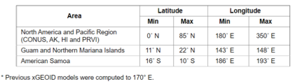
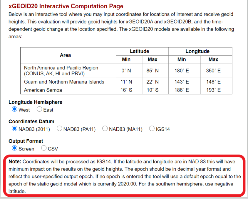
As the image above indicates, the xGEOID20 is available over a very large area. The box below lists the latitude and longitude boundaries of the areas where xGeoid20 is available.
Areas Where xGeoid20 Model Is Available. (Image: NGS)
To use the xGeoid20 Interactive Computation Page, the user can click on the “ACCESS TOOL” button below the map or the Interactive Computation button on the left side of the webpage (see the image above, “Experimental Geoid Models 2020 (xGEOID20)”). I’d like to highlight a statement that NGS added as a note on the computation page:
Coordinates will be processed as IGS14.
The epoch should be in decimal year format and reflect the user-specified output epoch. If no epoch is entered, the tool will use a default epoch equal to the epoch of the static geoid model, which is currently 2020.00.
The user needs to know that the epoch is used to compute the xDGEOID20 value. I will demonstrate how this works later in this column.
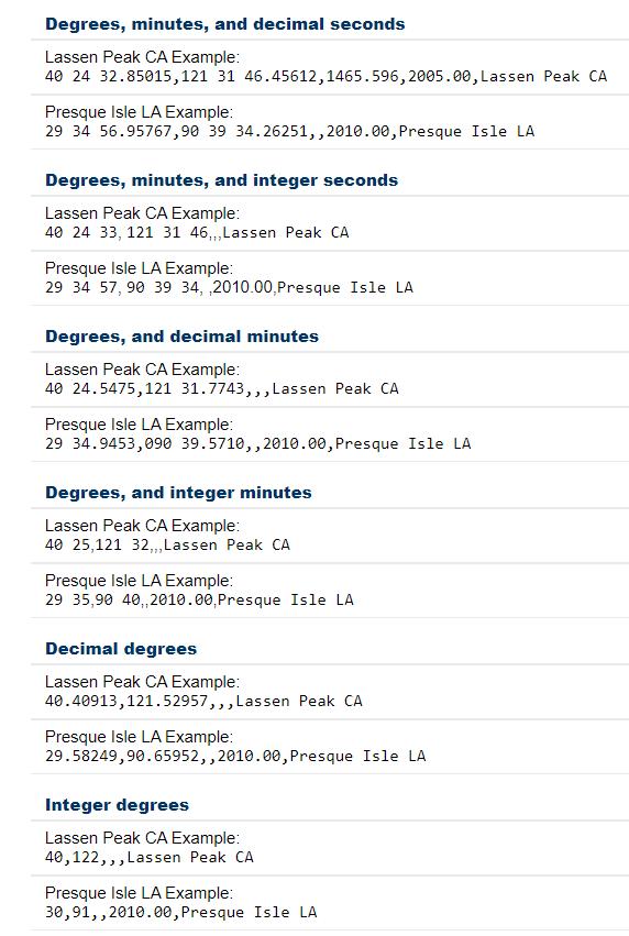
As in past xGeoid interactive computations web applications, the user can submit data in various formats. The box titled “Input Formats Permitted for xGeoid20 Webtool” provides a list of the permitted formats. It should be noted that inputting an ellipsoidal height, epoch and name are optional. However, the default epoch is 2020.00, so if you want a different epoch, you need to enter the date. Also. the program will only compute an orthometric height if the user provides an ellipsoidal height.
Input Formats Permitted for xGeoid20 Webtool. (Image: NGS)
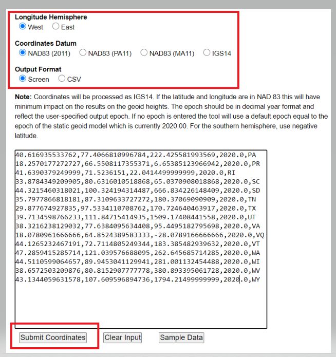
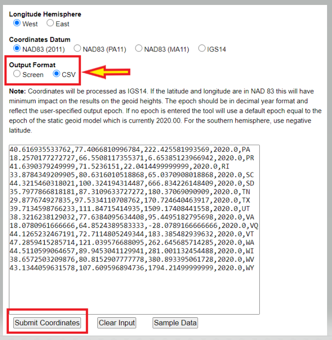
Users have the option of getting the output from the xGeoid20 tool on their computer screen or in the CSV format. The box below is an example of inputting data using the screen option. Once you enter your data, the user clicks on the submit button.
Example of Input Format for Screen Option. (Image: NGS)
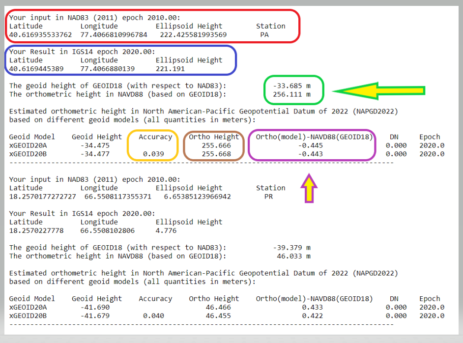
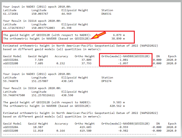
The next image shows an example of the output using the screen option. I have highlighted a few numbers that I’d like to address.
Your input in NAD83 (2011) epoch 2010.00 (red). I entered my coordinates as NAD 83 (2011), and it assumed that these coordinates are epoch 2010.0.
Your Result in IGS14 epoch 2020.00 (blue). The routine provides your output coordinates in IGS14, epoch 2020.00. This is the epoch of the static geoid model.
The geoid height of GEOID18 (with respect to NAD83) and the orthometric height in NAVD88 (based on GEOID18) (green). This NAVD 88 value is for comparison purposes only. It is using GEOID18 and provides an estimate of the differences between the future NAPGD2022 and the current NAVD 88. The orthometric height is computed using the following formula: NAD 83 (2011) ellipsoid height (epoch 2010.0} minus GEOID18.
Ortho Height (brown). This is the estimation of the orthometric height using the following formula: IGS14 ellipsoid height (epoch 2020.0} minus xGEOID20A (or B).
Ortho(model)-NAVD88(GEOID18) (purple). These differences are the estimates of the differences between the future NAPGD2022 and the current NAVD 88. It provides the differences for both the xGeoid20A and xGeoid20B model. I look at the B model because it used the GRAV-D data in the development of the model.
Accuracy (yellow). This is the estimated 95% confidence interval for geoid height.
Example of Output Format from Screen Option
xGEOID20 Interactive Computation Output
Note: The GRS80 ellipsoid is used for both NAD83 and IGS14.
N: The geoid height at epoch t0 = 2020.0, which is geocentric and relative to the GRS80 reference ellipsoid.
Accuracy: Estimated 95% confidence interval for geoid height.
DN: The time-dependent geoid change computed between user inputted epoch (t) and t0. To obtain the dynamic geoid height at user inputted epoch (t), add N + DN.
Either Model A or Model B N values may be used for this depending on user preference.
Example of Output Format from Screen Option. (Image: NGS)
The box below shows an example of inputting data using the CSV option.
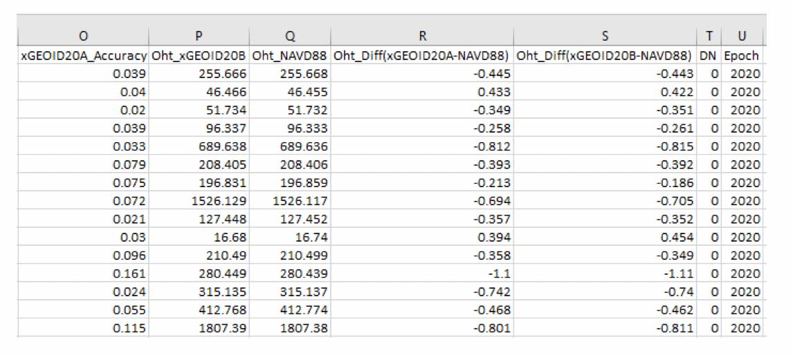
Example of Output Format from CSV Option
Note: The GRS80 ellipsoid is used for both NAD83 and IGS14.
N: the geoid height at epoch t0 = 2020.0, which is geocentric and relative to the GRS80 reference ellipsoid.
Accuracy: Estimated 95% confidence interval for geoid height.
DN: the time-dependent geoid change computed between user inputted epoch (t) and t0. To obtain the dynamic geoid height at user inputted epoch (t), add N + DN. Either Model A or Model B N values may be used for this depending on user preference.
Example of Input Format for CSV Option. (Image: NGS)
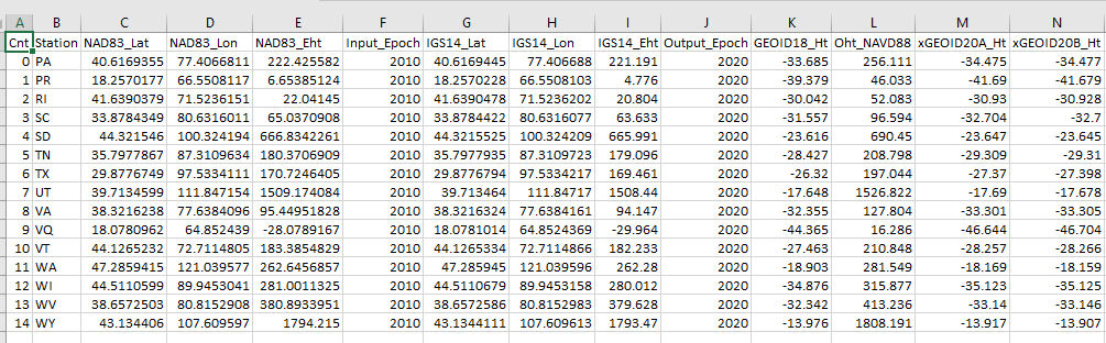
The printed output from the CSV option looks very confusing, but it can be imported into an excel spreadsheet. The headings and values are all separated by a comma so everything falls into the appropriate columns after importing the data (see image below.)
Example of CSV Output Format Imported into Excel. (Screenshot: David Zilkoski)Example of CSV Output Format Imported into Excel. (Screenshot: David Zilkoski)
I stated in the xGeoid20 write up that the dynamic geoid model has also been updated this year in the form of xDGEOID20. This model is produced by NGS within the Geoid Monitoring Service (GeMS) and is part of the new NAPGD2022. For a thorough discussion on GeMS and the time-dependent geoid, view the webinar from NGS’ presentation library. See the box titled “GeMS Webinar by Kevin Ahlgren.”
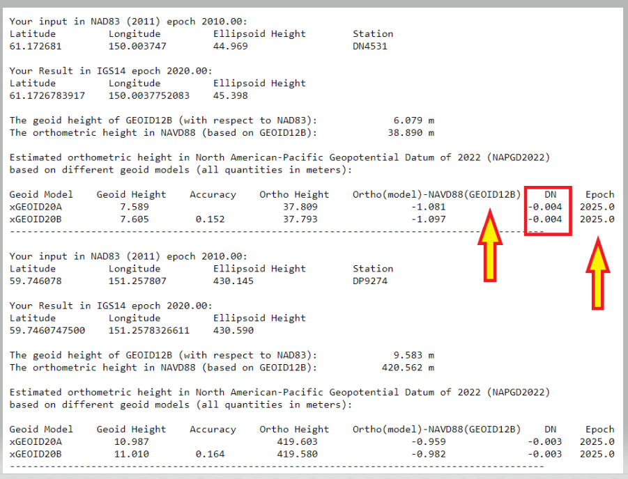
Also, one of my previous columns described NGS’ GeMS program. The images titled “Examples of the Time-Dependent Geoid Change in Alaska EPOCH 2020.0” and “Examples of the Time-Dependent Geoid Change in Alaska EPOCH 2025.0” show the change in geoid value from Epoch 2020 to Epoch 2025 for two stations in Alaska.
Examples of the Time-Dependent Geoid Change in Alaska EPOCH 2020.0. (Image: NGS)Examples of the Time-Dependent Geoid Change in Alaska, EPOCH 2025.0. (Image: NGS)
First, looking at the box titled “Examples of the Time-Dependent Geoid Change in Alaska EPOCH 2020.0,” the change between NAPGD2022 and NAVD 88 is approximately 1 meter. Users should note that the GEOID12B is used to establish the NAVD 88 height. Alaska was not included in GEOID18. Comparing the two Alaska labeled boxes, the xDGEOID2022 change between 2020.0 and 2025.0 is –4 mm. I will address this topic in more detail in future newsletters.
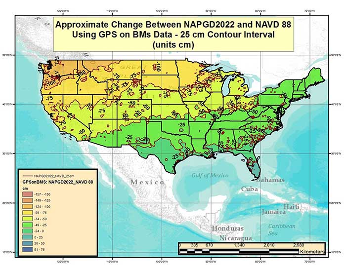
As stated by NGS news announcement, “The xGEOID models provide a preliminary but increasingly-accurate view of the changes expected from the upcoming North American-Pacific Geopotential Datum of 2022 (NAPGD2022).” NGS has produced many figures that describe the bias and trend between the future NADGP2022 and NAVD 88. In my June 2017 column I provided a plot that depicted the difference between NAPGD2022 and NAVD 88 based on the GPS on Bench Mark dataset. See the image below.
Figure from June 2017 Survey Scene column. Approximate Change Between NAPGD2022 and NAVD 88 Using GPS on BMs Data (units = cm). (Image: NGS)
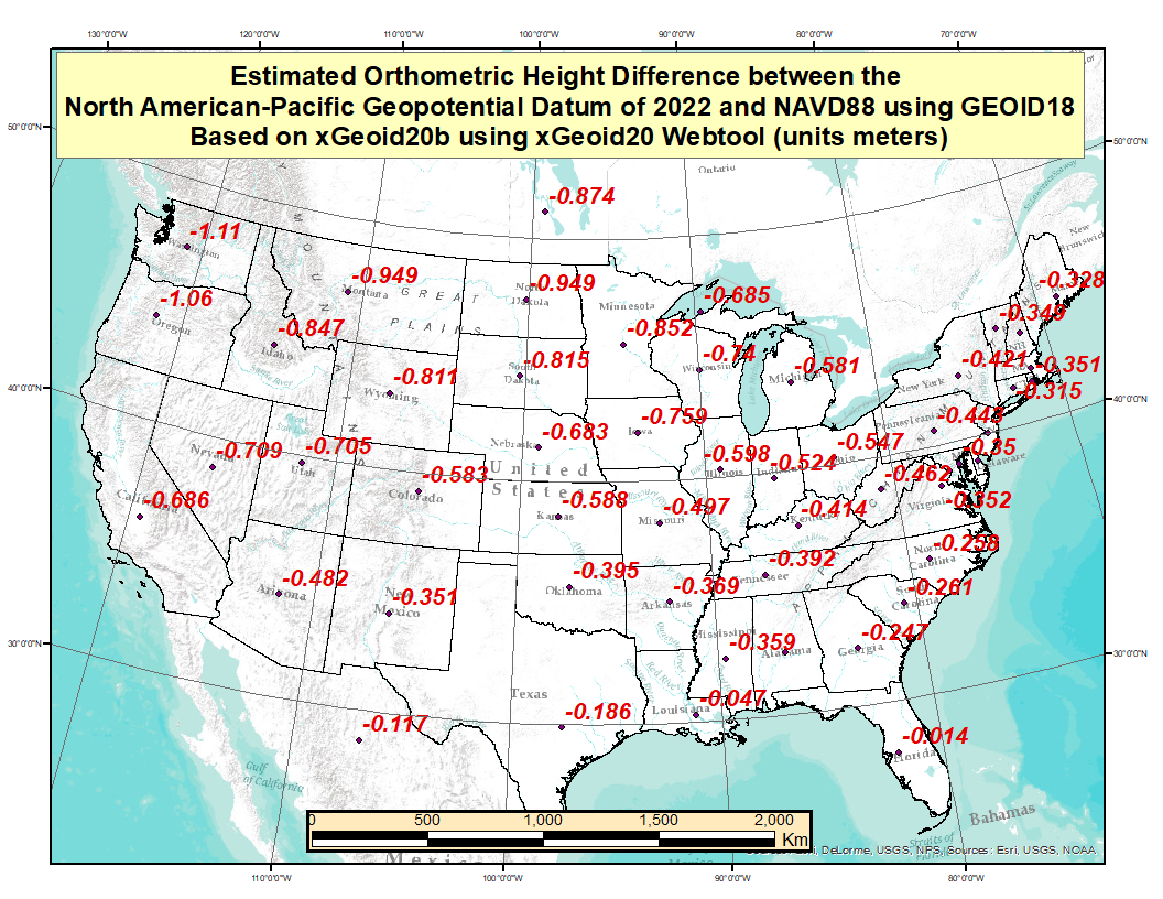
These figures provide a broad picture of the change but to better understand the changes across the Nation, I used the GPS on Bench Mark dataset, that was involved in the creation of Geoid18 model, to compute an average latitude, longitude, and ellipsoid height for every State. Obviously, this is a fictitious mark but it provides an idea of the average change based on marks that have both a GNSS-derived ellipsoid and a leveling-derived orthometric height. The plot titled “Difference Between the Future NAPGD2022 and NAVD 88” depicts the average difference for each state based on the GPS on Bench Mark data file. These differences were generated using the xGeoid20B values from the output of the xGeoid20 website.
Difference Between the Future NAPGD2022 and NAVD 88. (Image: NGS)
I would encourage everyone to select a couple of marks and compute the differences to understand the change in their particular region. I was the NAVD 88 Project Manager and I informed users of the potential changes between the NGVD 29 and NAVD 88 for about a decade, and I still had surveyors tell me that they didn’t know it was coming. Please take a few minutes to read NGS’ write up on xGEOID20, estimate the differences in your area of interest, and spread the word to your colleagues, friends, and clients.
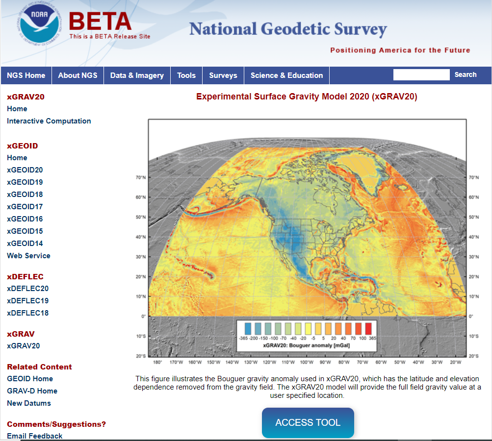
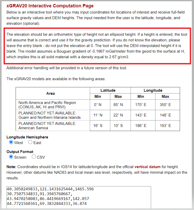
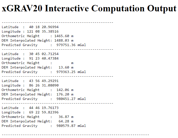
The last item that I’d like to highlight is that NGS has released a beta version of a surface gravity model consistent with xGEOID20. See the box titled “Experimental Surface Gravity Model 2020 (xGRAV20).” Users can access the beta webtool here.
The box below provides the output using the tools sample data.
Output from Screen Output Format from xGRAV20 Tool. (Image: NGS)
This gravity tool will be important when users want to incorporate leveling-derived orthometric heights into NAPGD2022. We will address this tool in more detail in future newsletters. I want to emphasis that these two web tools are beta sites. As a beta site, users should verify all information from the site. I encourage everyone to access the tool and check out a few of their favorite marks, and then send an email to NGS informing them of what you like, what you would like to change, and what you would like to see added to the tool.
NGS is releasing this tool as a beta product to get feedback from users. They are interested in your feedback concerning its function and usability as well as how users would like to interact with NGS web tools in the future. Email NGS at [email protected].
In conclusion, I want to leave you with a thought about change. When I give presentations and seminars, I usually include a slide that probably expresses the thoughts of many individuals.
My brother once told me:
“If you geodesists did it correctly the first time you wouldn’t have to keep performing adjustments and changing the values. Just do it right the first time.”
He’s a doctor and said he must do it right the first time.
My response to my brother and to everyone else is the following:
If you want to improve you have to be willing to change, and if you want to continue to meet future positioning requirements you need to continually change.
Winston Churchill said it better “To improve is to change; to be perfect is to change often.”
The Institute of Navigation (ION) has announced the new members of its Executive Committee, Council and Standing Committee Chairs following its Annual Awards during the ION International Technical Meeting and Precise Time and Time Interval Systems and Applications Meeting, both held virtually Jan. 25-28.
The ION Executive Committee, Council and Standing Committee Chairs will serve a two-year term.
“ION has a distinguished and passionate group of positioning, navigation and timing professionals in key positions to advance the goals of the organization.” said Lisa Beaty, executive director at ION.
The new members include:
ION Executive Committee
• President: Frank van Diggelen, Google
• Executive Vice President: Sherman Lo, Stanford University
• Treasurer: Frank van Graas, Ohio University
• Eastern Region Vice President: Jason Rife, Tufts University
• Western Region Vice President: Tim Murphy, The Boeing Company
• Satellite Division Chair: Patricia Doherty, Boston College
• Military Division Chair: John Langer, The Aerospace Corporation
• Immediate Past President: Y. Jade Morton, University of Colorado at Boulder
Council members
• Eastern Council Member-at-Large: Seebany Datta-Barua, Illinois Institute of Technology
• Eastern Council Member-at Large, Sanjeev Gunawardena, Air Force Institute of Technology
• Western Council Member-at-Large: Paul McBurney, OneNav
• Western Council Member-at-Large: Jihye Park, Oregon State University
Technical representatives
• Fabio Dovis, Politecnico Di Torino, Italy
• Christoph Gunther, German Aerospace Center, Germany
• Allison Kealy, RMIT University, Australia
• Nobuaki Kubo, Tokyo University of Marine Science & Technology, Japan
• Alexander Mitelman, AMM Technical Consulting
• Madeleine Naudeau, Air Force Research Laboratory
• Laura Norman, NovAtel, Canada
Standing Committee Chairs
• Awards Chair: Michael Meurer, German Aerospace Center, Germany
• Bylaws Committee: Deborah Lawrence, Federal Aviation Administration
• Ethics Chair: Heidi Kuusniemi, University of Vaasa & Finnish Geospatial Research Institute, Finland
• Fellow Selection Chair: Terry Moore, United Kingdom
• Finance Chair: Gary McGraw, Collins Aerospace
• Meetings Chair: Jeff Martin, Spirent Federal Systems
• Membership Chair: Okuary Osechas, German Aerospace Center, Germany
• Nominating Chair: Y. Jade Morton, University of Colorado at Boulder
• Publications Chair: Richard B. Langley, University of New Brunswick, Canada
• Technical Committee Chair: Sherman Lo, Stanford University
Fusing Automotive Radar and OBD-II Speed Measurements with Fuzzy Logic
SYN·ER·GY/ˈsinərjē/ noun: the interaction or cooperation of two or more organizations, substances, or other agents to produce a combined effect greater than the sum of their separate effects; from the Greek, “working together.” That is how the Oxford Dictionary defines this useful property that we often apply to business activities and other human interactions. But it can just as well describe the basis of an apparatus such as a navigation system that consists of several devices working together to produce a safer and more accurate result.
We all know that GPS or any GNSS for that matter doesn’t work everywhere all the time. For example, in built-up areas, signals can be blocked and reflected by buildings leading to positioning errors or complete outages. That is why it is quite common nowadays to combine a GNSS receiver together with an inertial measurement unit or IMU (often in the same package) to produce a more reliable solution for continuous navigation. But IMUs drift and so during an extended GNSS outage, the fidelity of the position reported by the GNSS plus IMU system will degrade with time. And so additional sensors must be added to the mix to improve the reliability of the navigation system. LiDAR, cameras, altimeters and so on have all been used severally or individually to augment the basic GNSS plus IMU combination. Self-driving cars, for example, use multiple sensors to provide safe navigation under specific conditions. Such specialized systems are quite expensive and so we might ask: Can the basic combination of GNSS and an IMU (or some of its components) be augmented by measurements already available in most vehicles or provided easily and inexpensively by equipment add-ons?
Yes. One measurement that helps is the forward speed of the vehicle. This is available from the vehicle’s on-board diagnostics computer system that tracks and regulates a car’s performance. Car manufacturers have adopted a standard for reporting data, the latest version of which is OBD-II. It is easy to interface to the OBD-II connector in a vehicle and extract the speed measurements – the same measurements displayed by the vehicle’s speedometer. Another potential source of speed measurements is the radar in most modern vehicles used for adaptive cruise control. That measurement is hard to acquire and has other limitations. But the idea to use radar as an input to a navigation system is a good one and easily obtained and installed radar units can be used instead.
But how do you optimally combine all of these sensor readings to produce reliable navigation? In the Innovation article this month, we take a look at how fuzzy logic can be used to get a reliable speed estimate, how that can be combined with accelerometer and gyroscope measurements to get position, velocity and attitude of a vehicle and, lastly, how that can be combined with GPS-derived position and velocity in an extended Kalman filter to produce an integrated navigation solution. Now that’s synergy.
Abosekeen
Standard land vehicles and self-driving cars have acquired precise navigation solutions to improve safety and assist drivers. GNSS is used as the primary source of the navigation solution for such applications. However, when driving in environments such as urban canyons, tunnels, or under bridges, GNSS signal reception deteriorates. Worse, it may suffer from a full outage. Because of this, we need a supplemental or backup system, such as an inertial navigation system (INS). The INS provides a complete navigation solution, and it is not affected by signal deterioration or jamming. GNSS/INS integration can achieve better accuracy than GNSS alone. However, such efficiency cannot be maintained during extended GNSS outages, especially with low-cost and commercial-grade inertial sensors for the INS. This drawback principally occurs because the INS solution suffers from accumulated error growth over time. This error causes path or trajectory drift, which becomes significant in the long term.
The fusion between an INS and a GNSS-based system provides a more robust solution than each system alone. In particular, INS/GNSS integration requires both systems to provide the vehicle with an accurate solution. However, when the vehicle is in challenging environments, the GNSS receiver cannot successfully update the integration filter, leaving the INS as the only source for the solution. When a GNSS outage is prolonged in some extreme situations, the solution quality deteriorates rapidly from INS drift. In particular, when using a micro-electromechanical system (MEMS) based inertial measurement unit (IMU), the drift rate significantly increases.
Several approaches have been introduced to overcome such drawbacks. Our reduced inertial sensor system (RISS) concept can be a replacement for the INS in land vehicle and ground robot applications. RISS can provide a complete navigation solution with fewer sensors than a standard INS. It is easily implemented for common land or self-driving vehicle navigation because it uses the vehicle’s on-board diagnostics standard II (OBD-II) device to determine the vehicle’s forward speed. INS requires two integration steps for positioning, but using the OBD-II speed measurements in the RISS mechanization requires only one.This reduction reduces the drift rate because it limits error accumulation from the integration process.
RISS depends mainly on OBD-II speed measurements to provide the land vehicle forward velocity. Unfortunately, these speed measurements are vehicle-specification dependent. Furthermore, these speed measurements are vulnerable to several types of error sources that can be categorized as deterministic (systematic) and non-deterministic (non-systematic). Deterministic errors come from wheel-diameter changes due to variations in temperature, pressure, tread wear, speed, unequal wheel diameters between the different wheels, inefficient wheelbase (track width), limited resolution and sample rate of the wheel encoders. Non-deterministic error sources include wheel slips, uneven road surfaces and skidding. Both groups of error sources negatively affect the velocity, traveled distance and heading estimations using the speed measurements from the OBD-II device.
Accordingly, we have made several RISS modifications to enhance performance, such as integration with a GPS receiver by enhancing the system design matrix for the integration filter. Moreover, an azimuth measurement update from magnetometers was added to the RISS/GPS integrated navigation system to provide azimuth updates during GPS outage periods, so the system can ensure more reliable positioning accuracy in challenging GNSS environments. Furthermore, we introduced a radar-based RISS to overcome OBD-II speed measurement errors. With this system, we demonstrated the superiority of using a frequency modulated continuous wave (FMCW) radar as a speed source instead of the one based on the OBD-II device. Automotive adaptive cruise control (ACC) mainly uses the Doppler measuring technique to measure the target’s (the vehicle ahead’s) relative distance and velocity. The primary radar unit’s radiation pattern is supposed to be a narrow beam to avoid other moving objects. Unfortunately, clutter affects forward-looking radar-collected data. Besides, extracting the onboard vehicle’s speed is difficult primarily because of the radar installation position.
We improved the use of ACC by modeling the linear and non-linear error components with Fast Orthogonal Search as a non-linear system identifier. This provided a more precise solution during outages extending from 60 seconds to 10 minutes. Furthermore, vehicle positioning using ACC was enhanced by extracting the primary and target vehicles’ relative distances under specific rules in urban canyons. These results encouraged us to introduce a fusion between the RISS and ACC, developing a more robust navigation system that relies on more than one sensor type.
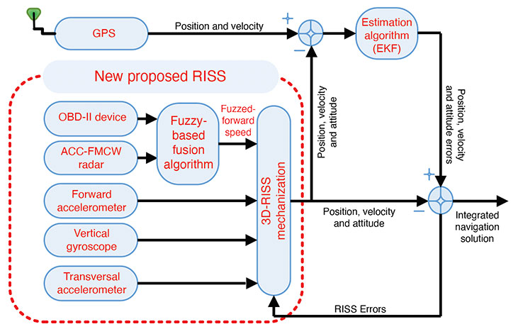
In this article, we propose a smart fusion technique to produce more accurate velocity information from both the Doppler radar and the OBD-II speed measurements. Our new RISS mechanization for land vehicle navigation uses the fused speed from the radar and the OBD-II device with a vertical gyroscope and two transversal accelerometers.
3D-RISS MECHANIZATION
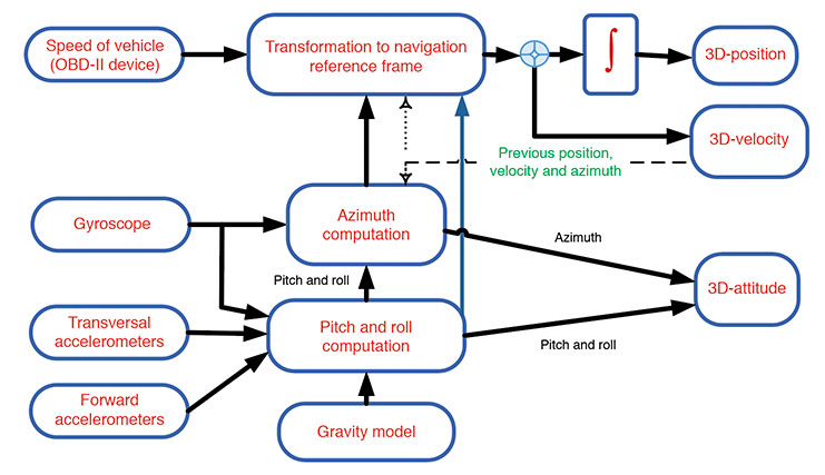
Our approach relies on a RISS incorporating a single-axis gyroscope, accelerometers, and speed measurements. Two accelerometers are used to estimate the pitch and roll angles instead of using two additional gyroscopes. Speed from the OBD-II device and heading information from the gyroscope aligned with the vehicle’s vertical axis enables the calculation of velocity, as shown in FIGURE 1. Calculating pitch and roll from accelerometers rather than gyroscopes retains RISS’s low cost while avoiding the gyroscope’s underpinning integration of velocity and position errors. When pitch and roll are calculated from accelerometers, the first integration of the gyroscope to obtain pitch and roll is eliminated, and thus the error in pitch and roll is not proportional to time integration.
FIGURE 1. Block diagram of speed measurements from the OBD-II device and RISS mechanization. (Image: Authors)
ACC-RADAR-BASED RISS
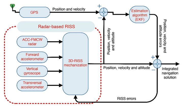
The radar-based RISS mechanization can provide a complete navigation solution (including 3D position, velocity and attitude) using a reduced number of sensors compared to the classic INS. It consists of longitudinal and transversal accelerometers, one vertical gyroscope and one radar unit (see FIGURE 2). In this mechanization, the OBD-II-device-related measurements are replaced by those extracted from the FMCW radar.
Data fusion is the process of combining data from multiple sensors and related information to achieve more specific inferences than can be achieved by using a single, independent sensor. Fusion processes are often categorized into three modes — low, intermediate and high-level fusion:
Data level combines several sources of the same type of raw preprocessed data to produce a new data set expected to be more informative and useful than the inputs.
Feature level combines features such as edges, lines, corners, textures or positions into a feature map used for the segmentation of images, detection of objects, and so on.
Decision level combines decisions from several expert modes. Methods of decision fusion are voting, fuzzy logic and statistical methods.
Various approaches for multi-sensor data fusion including weighted average, Bayesian estimators, adaptive observers, algebraic functions, fuzzy logic, neural network, soft computing, non-linear system fusion, and Kalman. Drawbacks of these methods include:
the necessity of adding new sensors to the system.
use of linear estimation models that need previous knowledge of signal statistics.
the presence of more than one faulty signal — an essential limitation of the performance.
the need to understand the behavior of the system to generate governing rules.
We used a data-clustering approach, which divides the data from a particular set into subsets (clusters) based on similarity. It could be defined as a reorganizing process for the dataset.
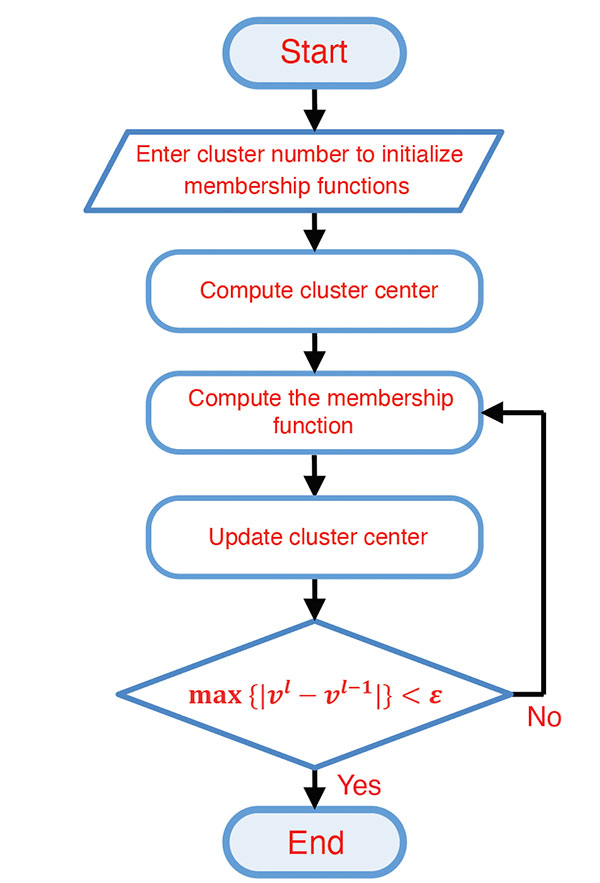
Fuzzy C-means (FCM) Algorithm. The FCM clustering algorithm represents the “fuzzify” step in the fuzzy system and is based on the minimization of an objective function called the C-means functional. The FCM algorithm (FIGURE 3) computes the standard Euclidean distance norm, which induces hyperspherical clusters. Hence it can only detect clusters with the same shape and orientation because the common choice of the norm-inducing matrix is the identity matrix. Three parameters in this algorithm have to be determined at the beginning: the number of clusters, the weighting parameter representing the system’s fuzziness, and the ending threshold, respectively.
FIGURE 3. FCM flowchart. (Image: Authors)
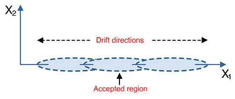
Cluster Number Selection. The FCM algorithm required predefining the number of clusters (Figure 3). This number can be entered randomly, taking iterations and time to converge to the best number, or be calculated. Many methods could be used, such as the validation parameters but only in an offline mode, or by using the data distribution itself and calculating the probability density function (PDF) by first calculating the data’s kernel and then calculating the PDF. This process can be done using the smooth kernel density estimator (SKDE), which is a powerful real-time approach. The main idea is that the measurements values drift in two directions around the acceptable region of measurements (see FIGURE 4). The number of clusters has to be determined in every instance of measurement. From the same figure, the partitions may be three if the drift was in two directions from the accepted region or may be two partitions if the drift at any instance were to the left or to the right direction (one direction drift).
FIGURE 4. Measured data partioning. (Image: Authors)
Subsequently, the number of clusters is determined according to the following two rules, based on the kernel estimator’s maximum peak location: If the maximum peak of the SKDE is left- or right-skewed, then the number of partitions is two; if the maximum peak of the SKDE is centered, then there are three.
METHODOLOGY
The methodology of the implementation of our approach is divided into two parts. The first part utilizes the FCM explained in the previous sections to produce a fused vehicle forward speed from the radar and the OBD-II device. The second part uses the fused speed in the INS mechanization instead of using one sensor only. Further, the mechanization output is integrated with the GPS receiver to establish a more accurate navigation system.
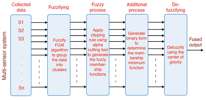
Sensor Fusion using Fuzzy Clustering. The data-fusion technique using the fuzzy clustering algorithm (FIGURE 5) consists of five main parts:
collecting data from the environment by using multiple sensors.
grouping the collected data by using the FCM algorithm in cluster form (“fuzzification”).
applying the fuzzy clipping rule using a cutting tool (fuzzy process).
making use of the clipping-rule properties to perform the fusion mechanism (additional process).
using the mean of the minimum to estimate the fusion output (“de-fuzzification”).
FIGURE 5. Sensor data fusion mechanization. (Image: Authors)
The first part is concerned with setting the sensors for measuring a particular phenomenon from the environment. The second part is to “fuzzify” these measured data, using the FCM to separate the sensors’ data to a certain number of clusters with membership matrix and cluster centers. The fuzzy process deals with the output clusters and membership functions through a fuzzy process called the fuzzy clipping rule. This rule divides the membership function into two regions: the upper region of the cutting threshold, which is clipped and is useless in the fuzzy environment, and the lower region from the cutting threshold, which is the useful region in the fuzzy environment.
Additional processes are applied to benefit from the previous stage — the existence of two regions, one useful, and the other not. This process aims to distinguish between the membership’s functions of the clusters. This could be achieved by generating a binary code that represents the membership function of the clusters. This binary code is generated by comparing the membership function with the threshold value. After the clustering process, each cluster membership function is represented as a binary code. The creation of this code depends upon the membership functions for the clusters and a variable threshold level.
The defuzzification part aims to extract the suitable value and in the same units as those of the measurements. This part produces the fusion output. This output comes from the minimum binary code, which denotes the selected suitable cluster membership function. This cluster contains the optimum solution. This solution or the fusion process output is determined by the centroid of the selected membership function.
Fusion-Radar-RISS/GNSS Integrated Navigation System. In this part of our technique, the fusion algorithm’s output is used in producing a full navigation solution as a control input of the RISS mechanization. This solution is subsequently integrated with the GPS receiver in a loosely coupled scheme using an extended Kalman filter (EKF). The overall proposed integrated navigation system is shown in FIGURE 6.
We carried out the experimental work to verify the proposed navigation system’s effectiveness by traveling real road trajectories. The testbed equipment was mounted inside and outside the test van.
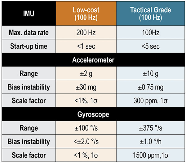
The interior testbed coincides with the van axes. It was rigidly and firmly fixed in the rear seat location using a standard seat chassis. For inertial sensors, we used both a low-cost MEMS IMU and a tactical-grade IMU. The specifications of these units are shown in TABLE 1.
TABLE 1. Performance characteristics of IMUs.
We used a dual-frequency GPS receiver with an output rate of 1 Hz. The tactical-grade IMU includes three fiber-optic gyroscopes and three MEMS accelerometers. The tactical-grade IMU and the GPS receiver were integrated using an off-the-shelf assembly developed by the manufacturer to provide a fully integrated, tightly coupled GNSS/IMU system that delivers a highly accurate 3D navigation solution. This tightly coupled integrated system from the manufacturer is used as a reference to compare the performance and the effectiveness of our proposed methods.
The FMCW radar development kit from the manufacturer was mounted on the front bumper. The unit’s working frequency is 24.5 GHz with a maximum frequency span of 1.5 GHz, a maximum update rate of 10 Hz, a maximum detectable speed of 215 kilometers/hour, and a 3 dB-beamwidth angle of 8.5°. The chirp frequency spans were adjusted to be 0.125 GHz. The maximum coverage range was 30 meters, and the minimum was 0.5 meters.
RESULTS AND DISCUSSION
We conducted a road test with the proposed approach in the downtown area of Kingston, Ontario, Canada, in August 2017.
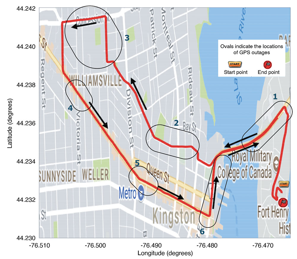
The trajectory followed is shown in FIGURE 7 projected on a Google map with the approximate locations of the outages. The reference is plotted in red, and the black arrows mark the direction of motion.
FIGURE 7. Road test trajectory with ovals indicating the approximate locations of GPS outages. (Image: Author)
Performance Evaluation. The proposed system performance was tested over six simulated outages. The outages have been selected to contain several dynamics such as turns, consecutive turns, stopping, crossing intersections, and straight driving. Furthermore, the outages occurred at different speed levels. The proposed system performance was compared to the traditional RISS/GPS and Radar/RISS/GPS integrated navigation system. The comparison criteria are 2D-position root-mean-square error (RMSE) and the maximum errors.
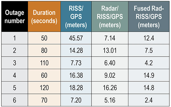
We compared our results using the radar-only versus OBD-II device test. TABLE 2 shows the RMSE of the 2D-position from the three systems in meters. Notice that the proposed system’s performance is better than the other two systems during four of the six outages. This result was achieved using the smart fusion technique to fuse the FMCW radar and the OBD-II speed measurements. Accordingly, the obtained speed is positively affecting the overall system performance.
TABLE 2. 2D-Position RMS-error for the low-cost INS unit during outages.
The average 2D-position RMSE reached 18.24 meters when using the OBD-II speed measurements only and 9.5 meters when using the radar only. On the other hand, the RMSE reached 9.4 meters when using the fusion between the two systems. The improvement percentage was 48.4% when applying the proposed integrated navigation system and 47.8% when using the radar-based system. The results show that the proposed system outperformed the other systems in outages 2, 3, 5 and 6 but did not do better than the radar-based system in outages 1 and 4. We highlight three outages.
The first outage had two left turns after a stop sign over a slippery road. This outage lasted for only 50 seconds, but the system’s behavior was due to wrong measurements combined with a complicated driving scenario when using the traditional RISS/GPS. On the other hand, the radar-based RISS/GPS produces a better solution because of having better velocity measurements in the mechanization, which provides the navigation filter with a better navigation solution. The proposed system limits the drift to around 16.7 meters, while the traditional system had a 68.7-meter drift in its solution.
The proposed system based on the fusion between both speed sensors — OBD-II and radar — could not compete with the radar because of the enormous gap between the two sensors and the lack of extra sensors. Despite that, the system produced a solution with 2D-RMSE of 22 meters, which is also better than the traditional RISS based on the OBD-II device and close to the results from fusing the radar. This problem can be solved by using an extra radar unit, typically installed with an ACC system. The system usually uses six radar units, two in the front and four at the vehicle’s corners.
The second outage duration was 80 seconds and contained two consecutive turns, right then left. The radar-based system reduced the solution drift from 28.13 to 23.58 meters. In contrast to the previous outage, the proposed system reduced the 2D-position maximum error to 14.2 meters. The proposed system’s result is superior to the radar-based system, which performed better in the previous outage because the OBD-II and radar measurements gap is not as large as the previous outage. The dynamics, the average speed and the road surface differ from the first outage.
The third outage was chosen to be a slight turn and mostly straight driving with an average speed of 60 kilometers/hour. This outage lasted for 110 seconds, and the proposed system holds the solution error growth down to 8.9 meters. The traditional system had a higher error growth rate and held it to 20.6 meters, and the radar-based system error reached 14.92 meters. This outage contained fewer dynamics when compared to other outages. Moreover, the slippage and false counting by the OBD-II device was not as considerable as in the first outage.
CONCLUSIONS AND FUTURE WORK
The performance of using a multi-sensor data-fusion technique based on fuzzy clustering successfully fuses the data measured by both the radar and the OBD-II device to produce a more robust forward speed of a moving land vehicle. The proposed system performance tested during six simulated GPS outages containing various dynamics significantly improved the overall navigation system, especially when the GPS signals were blocked. Finally, the fusion between multiple sensors leads to better performance if there are enough sensors or a fault-detection system to prevent the faulty sensor from biasing the fusion results. Moreover, the results demonstrate the superiority of the proposed fused radar RISS/GPS over each system alone.
As an extension to work reported here, we plan to apply our approach with an extra number of sensors to avoid the kind of drift that happened in outage number one. In addition, we suggest that a sensor fault-detection smart algorithm be added to the system to detect and control faulty sensors.
ACKNOWLEDGMENT
This article is based on the paper “Enhanced Land Vehicle Navigation by Fusing Automotive Radar and Speedometer Data” presented at ION GNSS+ 2020 Virtual, the 33rd International Technical Meeting of the Satellite Division of The Institute of Navigation, Sept. 21–25, 2020.
MANUFACTURERS
Our testbed used a Crossbow (now Moog Crossbow, www.moog.com) MEMS-grade XBOW IMU300CC IMU and a NovAtel/Hexagon (www.novatel.com) IMU-CPT tactical-grade IMU. We also used a SPAN-OEM4 or SPAN-SE NovAtel/Hexagon dual-frequency GNSS receiver. The radar development kit used is a Sivers IMA (now Sivers Semiconductors, sivers-semiconductors.com) RK1001K/00.
ASHRAF ABOSEKEEN is a lecturer in the Department of Avionics Engineering, Military Technical College, Cairo, Egypt. He received a B.Sc. and M.Sc. in electrical engineering from the Military Technical College in 2004 and 2012, respectively. He received his Ph.D. from the Department of Electrical and Computer Engineering, Queen’s University, Kingston, Ontario, Canada, in 2018.
UMAR IQBAL is an assistant clinical professor in the Department of Electrical and Computer Engineering, Mississippi State University. He completed his Ph.D. in electrical and computer engineering at Queen’s University in 2012.
ABOELMAGB NORELDIN is a professor in the Department of Electrical and Computer Engineering, Royal Military College of Canada, Kingston, Ontario with a cross-appointment at both the School of Computing and the Department of Electrical and Computer Engineering, Queen’s University.
Orolia, through its Orolia Defense & Security business, announced in November 2020 the launch of M-code military GPS receivers in its line of positioning, navigation and timing (PNT) solutions.
The line includes M-code-enabled mobile mission timing and synchronization platforms, such as the SecureSync IDM resilient time and frequency reference solution, the first time server approved by the Defense Information Systems Agency (DISA), and the Versa mobile PNT platform to meet rugged size, weight, power and cost (SWaP-C) requirements.
M-code is a military signal used in the L1 and L2 GPS bands. It is required by congressional mandate for U.S. Department of Defense (DOD) military operations.
M-code is designed to enhance PNT capabilities and improved resistance to existing and emerging threats to GPS, such as jamming and spoofing. Operational benefits of M-code include:
a higher power signal that offers improved resistance to jamming and interference
advanced security features to prevent unauthorized access or exploitation
improved message formats and signal modulation techniques for faster and more accurate performance.
Orolia has long supported the DOD’s need for selective availability anti-spoofing module (SAASM)-enabled PNT equipment, explained Hironori Sasaki, president of Orolia Defense & Security. “This announcement emphasizes our move toward M-code and the availability of M-code in our products,” Sasaki said. “Our focus has always been on staying in sync with the DOD and providing the latest and greatest technologies.”
Orolia now supports M-code in all its user products and offers two capabilities: simulation and M-code-enabled end-user devices. “They will each have a different approval process for export,” Sasaki said. “We follow DOD guidance on getting that capability out there.”
SecureSync, which is SAASM-enabled, has been deployed with DOD for many years, so Orolia has “a very good install base” of these devices, according to Sasaki. “We are providing a very easy and seamless upgrade path to go from SAASM to M-code in that platform.” The company’s Versa platform consists of the VersaSync and the VersaPNT, both small form-factor PNT devices designed for rugged application in military vehicles or military aircraft.
DOD has given Orolia approval to advertise the fact that it has these capabilities in its products. “We are expecting shipments to start in early 2021,” said Sasaki. “So, we are well on our way in development, implementation and productization.”
“We have been focusing on providing products that have a modular architecture, both in software and hardware,” Sasaki added. “We are embracing this approach of open architecture and continue to support the DOD in providing different layers of sensing and PNT protection in a way that can be incorporated into future DOD systems.
“We have already demonstrated our ability to deliver PNT solutions in various form factors, so I think we are in a good position to continue pushing forward with that open architecture approach,” Sasaki said.
What should the new administration’s priorities be to make PNT more resilient?
We asked Brad Parkinson, the “Father of GPS” and a GPS World Editorial Advisory Board member, what the new U.S. administration’s priorities should be to make positioning, navigation and timing (PNT) more resilient. For more answers from board members, see below.
Brad Parkinson
Protect the Spectrum. Reverse FCC authorization for relatively high-powered Ligado transmitters that have been proven to degrade GPS and other GNSS operation for thousands of PNT users. All U.S. government departments and major user groups affected have pleaded with the FCC to reverse this terrible decision. There is little benefit from it to the American public.
Protect the rapidly evaporating and self-proclaimed Gold Standard of GPS. The GPS satellite designs are showing their age. They need to go to multiple launch (three at a time) and revert to simpler designs without the spot-beams and other weighty add-ons that greatly increase complexity and cost. The Chinese have added to BeiDou (a) inter-satellite precision ranging and wide-band communications, (b) geosynchronous satellites, probably with good spot-beam acquisition aids, and (c) a WAAS-like correction directly on the satellites, which may have accuracies down to real-time kinematic (RTK, perhaps a few centimeters). Also, they claim their basic accuracies to be better than GPS (it might be true!) — I think they already have operational retro-reflectors.
Allow and encourage export of the basic and quickest fix to jamming and spoofing for high-value PNT users. More than 40 years ago, we demonstrated, in hardware, a high anti-jamming receiver that could fly directly over a 10 kW GPS jammer and not be affected. We know that high-gain, digital beam-steering antennas will create close to immunity, but our manufacturers will not move this way because we cannot sell or use them on the international market.These devices, combined with inexpensive inertial components and the newer signals, would make PNT virtually immune to current threats of interference — both jamming and spoofing.
Move the military focus from alternative PNT techniques to seriously upgrading their receivers and useful signals. No current or reasonably anticipated alternative can provide the accuracy (3D), availability or integrity of GPS. The new M-code and L1C signals have been in the queue for about 20 years. (Loran for ground operations probably is very vulnerable to direct attack in a fluid battlefield operation. Loran’s main value is to distribute time and for maritime users.) In those 20 years, we now have cellphone chips costing less than $5 that can listen to about 200 ranging signals and process RTK, as well as use all the corrections available (WAAS, EGNOS, etc.). Such capability cannot be found in military receivers. The Defense Department must improve its acquisition strategy in terms of both speed and competition, and ncorporate existing civil capability into military user equipment.
Take government actions to rapidly identify, shut down, and prosecute GPS jammers. Some believe this problem is much larger than recognized already. All cellphones should be required to report extraordinary spectrum noise levels or apparent attempts at spoofing. This should be fed to a dynamic national database, perhaps maintained by the Coast Guard. GPS users should have an automated way to find out whether there are substantial threats in their operating area.
Brad Parkinson is the Edward Wells Professor, Emeritus, Aeronautics and Astronautics (recalled) and co-director of the Stanford Center for Position, Navigation and Time at Stanford University.
Editorial Advisory Board PNT Q&A
Here are additional responses to the question from more GPS World Editorial Advisory Board members.
John Fischer
“We hope the new administration continues on the path established with the Executive Order last year for resilient PNT, supporting progress made by DHS and NIST in establishing resilient and cybersecure frameworks. It will be important for them to maintain an open market concept toward future innovative solutions and not mandate a particular PNT approach. Awareness of the criticality for trusted PNT in our mobile connected society is established and we must not lose this.” John Fischer Orolia
Jules McNeff
“Resilient PNT should be a national security priority. Its continuity is vital to both military and economic/social activities of all kinds. Its qualities of spatial awareness and synchronization enable the efficient functioning of the most sophisticated modern technologies in the physical and cyber worlds while also simply getting people and things from point A to point B on schedule. In that context, the elements which comprise resilient PNT should be protected from natural or hostile disruption.” Jules McNeff Overlook Systems Technologies
Greg Turetzky
“Truly resilient PNT requires combining multiple positioning technologies to maximize resiliency. However, the government’s influence in many of the augmentation technologies (sensors, vision, etc.) is limited. What the administration can do is make GPS itself more resilient by speeding up the launch and acquisition schedule of GPS Block III. The new signals, particularly at L5, are invaluable for improved resiliency to jamming and spoofing as well as providing a significant improvement in accuracy.” Greg Turetzky Consultant
“Seen & Heard” is a monthly feature of GPS World magazine, traveling the world to capture interesting and unusual news stories involving the GNSS/PNT industry.
Lost and found
Taking video from an airplane window 300 feet up carries its share of risks, discovered Brazilian documentary filmmaker Ernesto Galiotto. The bad news: A strong wind snatched his iPhone 6 from his hand. The good news: GPS enabled him to recover the phone, which suffered only a minor crack in its protective cover. The best news: The phone captured the entire 15-second drop on video. The incident happened over Peró beach 75 miles east of Rio de Janeiro, reported Brazilian news outlet G1.
Photo: Land Life Company via Trimble
Finding particular trees in the forest
Locating and documenting a single tree in a forest planting can be difficult. Technicians at Land Life, an Amsterdam-based land restoration company, have switched from using QR codes and readers for tree identification to GNSS. By replacing the QR codes with accurate GNSS positioning, Land Life produced a four-fold increase in monitoring productivity. The company measures sapling height and health and combines that data with tree species, location, soils and environmental conditions to support planning and care. Field teams now use a Trimble R1 GNSS receiver to stream positioning data via Bluetooth to their smartphones.
Screenshot from video of Escoffier’s rescue/VendéeGlobe
Answering an SOS
Yacht skipper Kevin Escoffier faced disaster during the Vendée Globe solo round-the-world sailing race. His yacht was pounded apart in raging seas 840 nautical miles southwest of Cape Town, South Africa. Once his raft hit the water, its rescue beacon activated. Through the Cospas-Sarsat service, the signal moved from Galileo satellites to ground stations in Toulouse, France, to Canberra, Australia, then to race directors, who sent the closest competitor to assist.
India will be free of toll booths in two years, said Nitin Gadkar, the country’s transportation minister. According to the Times of India, the government will roll out GPS-based tolling across its national highway sytem. Tolls will be deducted directly from drivers’ bank accounts based on distance traveled. While commercial vehicles registered after January 2019 have tracking systems, the government has yet to outline plans to install GPS receivers in older private vehicles.
A roundup of recent products in the GNSS and inertial positioning industry from the January 2021 issue of GPS World magazine.
OEM
Receiver board
Enhanced with corrections
Photo: Septentrio
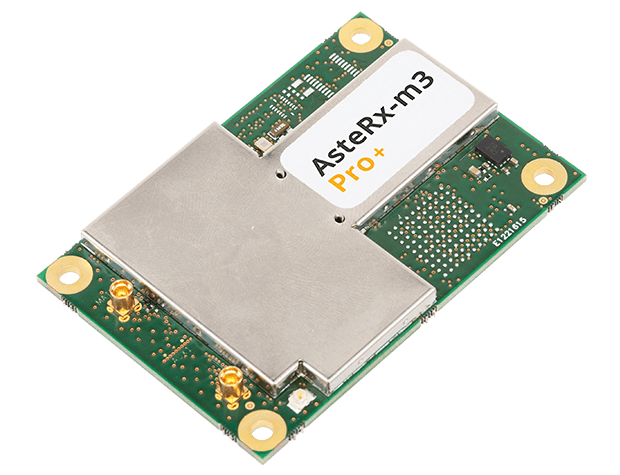
The AsteRx-m3 Sx OEM board dual-antenna receiver combines Septentrio’s latest core GNSS technology with the SECORX-S sub-decimeter correction service to enable plug-and-play positioning. High-accuracy positioning is available directly out of the box, GNSS corrections automatically streamed to the receiver. This significantly simplifies the set-up process and eliminates the need for corrections service subscription and maintenance. Corrections are delivered via internet or L-band satellites, ensuring sub-decimeter service even in remote locations where there is no easy internet access.
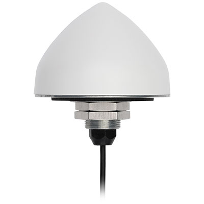
The new TW5382 smart GNSS antenna is designed for high-accuracy 5G timing. The TW5382 is a multi-band, multi-constellation 5G smart GNSS antenna/receiver that provides 5 ns (1-sigma, clear sky view) timing accuracy. It consists of two components: a Tallysman GNSS Accutenna technology antenna and a professional-grade GNSS timing receiver module. Accutenna supports the full bandwidth of the TW5382 receiver, strong multipath mitigation and deep filtering in a compact IP69K enclosure. These features enable the antenna to provide a strong, pure, in-band, right-hand circular polarized signal to the receiver. The TW5382’s professional-grade multi-constellation and multi-signal timing receiver tracks GPS/QZSS (L1/L2), GLONASS (G1/G2), Galileo (E1/E5b), and BeiDou (B1/B2) signals.
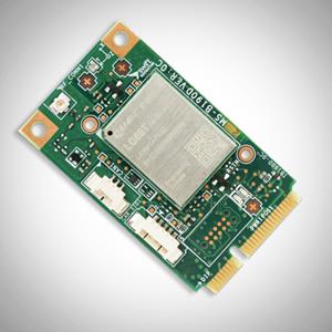
The new Precision GNSS Module (PGM) is designed to offer fast evaluation and a quick path to production for those requiring a precise positioning solution. It is available in a simple-to-use, industry-standard mPCIe (mini peripheral component interconnect express) format and is designed specifically for Swift’s Starling positioning engine running on a host application processor to deliver real-time precision navigation. The PGM utilizes STMicroelectronics’ TeseoV chipset in Quectel’s multi-constellation, dual-band LG69T-AP receiver to create an affordable, easy-to-use solution for customers building industrial, last-mile and internet of things (IoT) platforms. This solution operates with the highest accuracy when used with Swift’s Skylark positioning service.
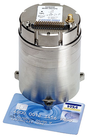
CAST Navigation tested Emcore’s SDN500 inertial navigation system (INS) in an ultra-high-altitude flight simulation and achieved success. The test required simulating performance at an altitude of more than 24,000 meters and velocities over 600 m/s. Only a few aircraft in the world have such capabilities, including the SR-71 Blackbird, but it is not practical to participate in a test flight on the SR-71. Simulating the SDN500 INS test flight to specific customer profiles on a CAST system is straightforward and cost-effective. Emcore relies on GNSS/INS simulators for hardware-in-the-loop testing to verify the expected performance of algorithms. Emcore sought to validate the velocity and altitude limits of a new GNSS receiver along with the algorithm performance in a tactical-grade SDN500 system.
The Dimensity 700 5G smartphone chipset is a system on chip (SoC) designed to bring advanced 5G capabilities and experiences to the mass market. MediaTek’s Dimensity family of 5G chips is designed to give device makers a suite of options for 5G smartphone models. The chips range from flagship and premium to mid-range and mass market devices to make 5G more accessible for consumers everywhere. GNSS signals received include GPS L1CA and L5, BeiDou B1I and B2, GLONASS L1OF, Galileo E1 and E5, QZSS L1C and L5, and NavIC.
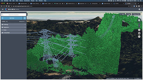
IHawk allows users to inspect sites remotely and then download and view the analysis anywhere in the world. It eliminates the need for engineers to climb towers for inspections or work in hazardous environments. The imagery and information gathered provides a detailed and highly accurate analysis of the condition of power transmission towers.
The Alpin UAS is a long-range, heavy-lift unmanned helicopter capable of carrying up to 160 kg with a range of up to 840 km. The UAS includes a wideband satellite communication channel from its command-and-control station — a valuable feature, particularly for operations in remote areas. The Alpin unmanned helicopter is able to withstand severe weather conditions, carry multiple payloads, and transmit real-time information to defense forces and decision-makers in the field. Its system autopilot has features and advantages such as fully autonomous take-off and landing, remote ground-control network capability, auto-rotation landing capability and high efficiency flight control based on a total energy control system (TECS).
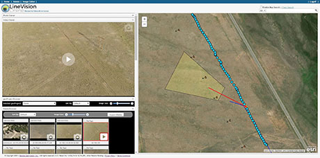
LineVision Online now provides enhanced support for visualizing and mapping DJI drone video camera metadata and field-of-view projections. The secure web application is designed for immersive mapping, analysis, search, sharing and archive of geo-referenced videos, full-motion video, photos and other survey, inspection and surveillance datasets. With enhanced camera metadata mapping in LineVision Online, DJI drone videos can now display a dynamic, field-of-view outline representing where the gimbal camera was looking on the Earth as the video plays in the web-based map interface. Users can select any point along the UAV’s flight track on the map to immediately cue the video to play what was recorded at that location click point.
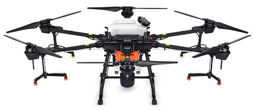
The Agras T20 drone can conduct autonomous operations over a variety of terrains, such as broad-acre farmlands, terraces and orchards. As a comprehensive spraying system, the T20 allows users to easily set flight and operation parameters. With a built-in real-time kinematic (RTK) centimeter-level positioning system and RTK dongles, centimeter-level waypoint recording is enabled, strengthening operations and ensuring precision spraying.The T20 is equipped with eight nozzles and high-volume pumps that can spray at a rate of up to 6 liters per minute. A highly optimized wind field produces droplets of the correct size and consistency. The T20 is also equipped with a new four-channel electromagnetic flow meter, which monitors and controls four hoses individually, ensuring an efficient flow rate for each nozzle.
A new virtual base station (VBS) feature is available in Qinertia, GNSS and inertial navigation system (INS) post-processing software. Trajectory and orientation are greatly improved by processing inertial data and raw GNSS observables in forward and backward directions. The VBS computes a virtual network around a project in which position accuracy is maximized, homogeneous and robust, such as a PPK short baseline. Once surveyors collect data, Qinertia chooses the most relevant reference stations, builds a virtual network and brings the project to centimeter-level accuracy with no convergence effects, even in urban areas.
Enview Explore is a powerful web application that leverages artificial intelligence and cloud computing to automatically process 3D data at a high speed and scale. Enview performs a variety of geospatial operations, including object recognition, feature extraction, feature-based change detection, and 2D/3D measurement. Enview’s technology has been deployed on thousands of square miles worldwide to protect vital infrastructure and support mission-critical operations. Its unique method for classifying 3D data reduces time to action by focusing on finding meaningful insights.
PDGrade — a machine guidance and positioning system that uses GNSS for pile driving applications — is now optimized for the solar industry with an increased capability in pile installation and navigation accuracy. It removes the need for surveying piles and reviewing as-built information by centralizing all relevant information and providing necessary details to operators and site supervisors.The system features both software and hardware applications to provide operators with detailed information such as pile navigation, pile location, positioning and height information, project progression tracking, and detailed accuracy. The PD machine is fitted with Carlson sensors and a ruggedized Windows-based MC10 tablet. The entire system is then calibrated within PDGrade.