General Atomics Aeronautical Systems Inc. (GA-ASI) is in the news again, as it got its prototype version of the U.S. Air Force (USAF) Collaborative Combat Aircraft (CCA) into the air for the first time, with an anticipated lengthy flight test campaign to follow. This latest CCA iteration, refered to as the YFQ-42A CCA, was derived from an earlier jet-powered XQ-67A Off-Board Sensing Station, a platform that enabled the company to not only develop and build but also fly this latest aircraft in just one year.
GA-ASI CAA makes first flight Aug. 27, 2025. (Credit: GA-ASI)
The UAV features significant autonomous capabilities developed over nearly five years of training using the MQ-20 Avenger unmanned jet aircraft. The strategy of beginning with a company-developed baseline aircraft (Avenger), securing USAF support for an initial derivative and then for the YFQ-42A CCA, appears to be accelerating development of the Loyal Wingman concept toward USAF operational manned-unmanned airborne teaming.
Previously, in July, GA-ASI began preparations to enable friendly European countries to rapidly participate in the future CCA-capabilites by teaming with its German affiliate General Atomics Aerotec Systems GmbH (GA-ATS). The agreement appears to enable high-volume local manufacture of a European CCA, and press releases have implied that potential content is expected to be provided by other high-tech local suppliers.
Following earlier reports that Reliable Robotics (RR) has been busy automating all phases of aircraft operations, including a Cessna Caravan cargo aircraft, USAF has awarded RR a $17.4 million contract to install a Reliable Autonomy System (RAS) in another Cessna. The resulting automated Cessna 208A Caravan is to be used in an estimated two-year program toward obtaining FAA certification that should enable flight within the U.S. National Airspace System (NAS). The system has been demonstrated — with a remote pilot in the loop — to be able to take an aircraft from startup on the ramp, through taxi, takeoff, en route flight, landing and taxi return to the ramp for unloading.
RR autonomous Cessna 208B takes off from Mojave Air and Space Port, California, on Aug. 8, 2024. (Credit: RR)
Cessna Caravans have been heavily used for cargo transport across the U.S. (and around the world) with a range of 1000 miles, carrying up to 1000 lb of cargo. The RR certification program is intended to allow these types of automated unmanned commercial and military operations on a regular basis throughout FAA controlled US airspace, alongside manned aircraft. Flying military unmanned aircraft in the NAS currently requires extremely highly-coordinated, continuous activity. The hope is that eventually it could become an easier more regular form of autonomous cargo/people air transport.
The cost of the continuing war in Ukraine may be affecting the Russian economy — a major drone manufacturer apparently is facing bankruptcy despite Russia currently using thousands of drones in attacks on Ukraine. The situation is difficult to understand, but this is an expensive war.
However it appears that, AO Kronshtadt, one of the major drone suppliers in Russia is also beset by civil lawsuits from several organizations to which it owes lots of rubles. Its Orion and an updated version Inokhodets drone are apparently somewhat similar to the US MQ-9 Reaper UAV.
AO Kronstadt employees assemble the Russian Orion UAV. (Credit: open source)
Russia has apparently converted the Orion/Inkhodets medium-altitude surveillance drone into a strike version, but with limited success. Nevertheless, Kronshtadt apparently has made some progress, selling an export version in Asia.
Meanwhile, Russia still is apparently producing up to 6,000 Shahed one-way drones per month by another manufacturer in the Alabuga Special Economic Zone at a unit cost of around $70,000. This is significantly lower than drones that were originally purchased from Iran at $370,000 each.
The U.S. Federal Government through its transport agencies apparently has the exclusive right to control drones, including bringing malicious UAVs down from the sky. Most people understand that the Federal Aviation Administration (FAA) regulates who flies what and where, but who is in charge of reducing and removing drone threats? It may have been difficult to understand during recent unauthorized overflights of military installations on the East Coast why someone didn’t shoot down the offending drones.
Now, a group of police agencies has approached members of Congress to ask for the right to “detect, track, identify and mitigate” the unlawful, negligent or malicious use of drones that threaten public safety. Citing a number of incidents — including drone incursions at airports and other incidents where unmanned aircraft have interfered with firefighting and disaster response, instances where law enforcement activities have been overflown and disrupted, and the practice of using drones to drop drugs, guns and mobile phones into prisons — the law enforcement group sees a need for permission to engage. With several major events scheduled across the U.S., it likely is time to support law enforcement with the appropriate powers needed to protect the public.
It is true that several bills are already pending before Congress to enable state, local, tribal and territorial law enforcement agencies to find, identify and possibly mitigate inappropriate drone activity, but the group is urging action now. And they clearly demonstrate the need to be able to stop drone activity when necessary — the federal government cannot cover the whole country all the time, so it makes more sense to adequately train law enforcement and to distribute authorized local mitigation activity whenever it is found to be necessary.
So a mixed bag this month — progress for the U.S. Collaborative Combat Aircraft initiative, more steps toward automation for air cargo transport, problems for one Russian drone supplier while others increase volume and the United States seeks options for better defense against them, and U.S. law enforcement seeks the capability to help mitigate drone incursions where they are not wanted — plenty of different angles to consider around unmanned aerial vehicles.
Adtran has launched the OSA 5401XG SyncPlug, an SFP-based grandmaster clock that delivers precise PTP and NTP synchronization for 10Gbit/s edge and access networks. The new Oscilloquartz device enables timing distribution through a compact, plug-in form factor that requires no rack space or complex installation, empowering network operators to extend synchronization into space- and power-limited deployments.
With multi-band GNSS support, compliance with PRTC‑B and compatibility with 10Gbit/s-only host platforms, it offers an efficient way to upgrade timing capabilities across sectors, including telecom, energy, defense, enterprise and more, according to Adtran.
“As networks evolve, precise timing has to reach further, faster and into more constrained environments. That’s exactly what the 5401XG SyncPlug is built for. It’s a no-compromise solution that fits directly into existing infrastructure, requires almost no space or power and delivers the performance needed for next-generation services,” said Gil Biran, GM of Oscilloquartz, Adtran. “By integrating advanced GNSS capabilities in a 10Gbit/s-ready SFP module, we’re giving our customers an easier, smarter way to deploy resilient timing, whether modernizing legacy sites, extending coverage at the edge or rolling out new, timing-critical applications.”
The OSA 5401XG SyncPlug is a fully featured SFP-based synchronization device that supports PTP grandmaster, boundary and slave clock modes, Stratum 1 NTP server functionality, and SyncE for frequency synchronization. It plugs directly into standard 1Gbit/s or 10Gbit/s ports and consumes less than 2.5W, making it ideal for space- and power-sensitive locations. With multi-band GNSS (L1 and L5), the device enables compliance with enhanced timing standards such as PRTC-B and supports regional systems, including India’s IRNSS. It also offers advanced spoofing and jamming detection, extended holdover and up to 500,000 NTP transactions per second, ensuring performance and security at scale.
“Demand for precise synchronization is growing rapidly across edge and access networks, and it has to be delivered with minimal footprint and maximum resilience,” commented Igal Pinhasov, VP of product line management at Oscilloquartz, Adtran. “From mobile backhaul and energy grids to secure government and business networks, the OSA 5401XG SyncPlug fits directly into existing infrastructure to deliver full grandmaster functionality over 10Gbit/s. There’s no need for extra cabling, appliances or rack space. It’s an ideal solution for operators looking to modernize timing in challenging environments while simplifying deployment and strengthening performance.”
A massive earthquake and subsequent tsunami off Russia in late July tested an experimental detection system that had deployed a critical component just the day before.
A recent tsunami triggered by a magnitude 8.8 earthquake off Russia’s Kamchatka Peninsula sent pressure waves to the upper layer of the atmosphere, NASA scientists have reported. While the tsunami did not wreak widespread damage, it was an early test for a detection system being developed at the agency’s Jet Propulsion Laboratory in Southern California.
Called GUARDIAN (GNSS Upper Atmospheric Real-time Disaster Information and Alert Network), the experimental technology “functioned to its full extent,” said Camille Martire, one of its developers at JPL. The system flagged distortions in the atmosphere and issued notifications to subscribed subject matter experts in as little as 20 minutes after the quake. It confirmed signs of the approaching tsunami about 30 to 40 minutes before waves made landfall in Hawaii and sites across the Pacific on July 29 (local time).
“Those extra minutes of knowing something is coming could make a real difference when it comes to warning communities in the path,” said JPL scientist Siddharth Krishnamoorthy.
Near-real-time outputs from GUARDIAN must be interpreted by experts trained to identify the signs of tsunamis. But already it’s one of the fastest monitoring tools of its kind: Within about 10 minutes of receiving data, it can produce a snapshot of a tsunami’s rumble reaching the upper atmosphere.
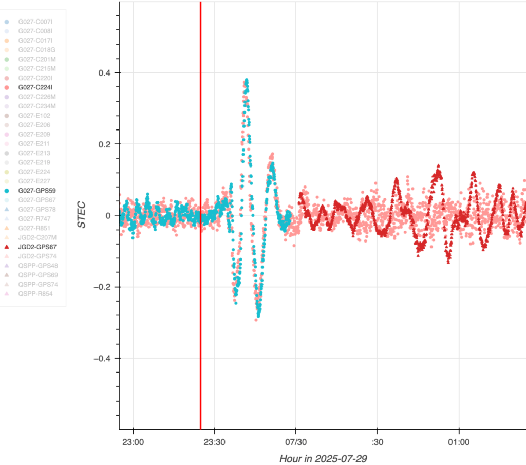
The dots in this graph indicate wave disturbances in the ionosphere as measured between ground stations and navigation satellites. The initial spike shows the acoustic wave coming from the epicenter of the July 29 quake that caused the tsunami; the red squiggle shows the gravity wave the tsunami generated. (Image: NASA/JPL-Caltech)
The dots in this graph indicate wave disturbances in the ionosphere as measured between ground stations and navigation satellites. The initial spike shows the acoustic wave coming from the epicenter of the July 29 quake that caused the tsunami; the red squiggle shows the gravity wave the tsunami generated.
The goal of GUARDIAN is to augment existing early warning systems. A key question after a major undersea earthquake is whether a tsunami was generated. Today, forecasters use seismic data as a proxy to predict if and where a tsunami could occur, and they rely on sea-based instruments to confirm that a tsunami is passing by. Deep-ocean pressure sensors remain the gold standard when it comes to sizing up waves, but they are expensive and sparse in locations.
“NASA’s GUARDIAN can help fill the gaps,” said Christopher Moore, director of the National Oceanic and Atmospheric Administration Center for Tsunami Research. “It provides one more piece of information, one more valuable data point, that can help us determine, yes, we need to make the call to evacuate.”
Moore noted that GUARDIAN adds a unique perspective: It’s able to sense sea surface motion from high above Earth, globally and in near-real-time.
Bill Fry, chair of the United Nations technical working group responsible for tsunami early warning in the Pacific, said GUARDIAN is part of a technological “paradigm shift.” By directly observing ocean dynamics from space, “GUARDIAN is absolutely something that we in the early warning community are looking for to help underpin next generation forecasting.”
How GUARDIAN works
GUARDIAN takes advantage of tsunami physics. During a tsunami, many square miles of the ocean surface can rise and fall nearly in unison. This displaces a significant amount of air above it, sending low-frequency sound and gravity waves speeding upwards toward space. The waves interact with the charged particles of the upper atmosphere — the ionosphere — where they slightly distort the radio signals coming down to scientific ground stations of GPS and other positioning and timing satellites. These satellites are known collectively as the Global Navigation Satellite System (GNSS).
While GNSS processing methods on Earth correct for such distortions, GUARDIAN uses them as clues. The software scours a trove of data transmitted to more than 350 continuously operating GNSS ground stations around the world. It can potentially identify evidence of a tsunami up to about 745 miles (1,200 kilometers) from a given station. In ideal situations, vulnerable coastal communities near a GNSS station could know when a tsunami was heading their way and authorities would have as much as 1 hour and 20 minutes to evacuate the low-lying areas, thereby saving countless lives and property.
Key to this effort is the network of GNSS stations around the world supported by NASA’s Space Geodesy Project and Global GNSS Network, as well as JPL’s Global Differential GPS network that transmits the data in real time.
The Kamchatka event offered a timely case study for GUARDIAN. A day before the quake off Russia’s northeast coast, the team had deployed two new elements that were years in the making: an artificial intelligence to mine signals of interest and an accompanying prototype messaging system.
Both were put to the test when one of the strongest earthquakes ever recorded spawned a tsunami traveling hundreds of miles per hour across the Pacific Ocean. Having been trained to spot the kinds of atmospheric distortions caused by a tsunami, GUARDIAN flagged the signals for human review and notified subscribed subject matter experts.
Notably, tsunamis are most often caused by large undersea earthquakes, but not always. Volcanic eruptions, underwater landslides, and certain weather conditions in some geographic locations can all produce dangerous waves. An advantage of GUARDIAN is that it doesn’t require information on what caused a tsunami; rather, it can detect that one was generated and then can alert the authorities to help minimize the loss of life and property.
While there’s no silver bullet to stop a tsunami from making landfall, “GUARDIAN has real potential to help by providing open access to this data,” said Adrienne Moseley, co-director of the Joint Australian Tsunami Warning Centre. “Tsunamis don’t respect national boundaries. We need to be able to share data around the whole region to be able to make assessments about the threat for all exposed coastlines.
Digital Yacht is offering OneFix , a high-performance GNSS sensor designed to offer positioning better than 1 m. The multi-constellation, dual-band sensor also has robust anti-spoofing algorithms to provide more reliable navigation.
The sensor can fit most popular navigation systems, including legacy units, as well as connect to iPads and tablets and the latest multi-function NMEA 2000 compatible displays.
OneFix incorporates a dual-band (L1 and L5) processor and works with GPS, Galileo, NavIC and Beidou to calculate a fix. GLONASS is available as an option with a second active antenna. Its advanced algorithm compares position fixes across all networks and frequencies to minimize spoofing and positional inaccuracies. The result is a highly reliable position fix which typically offers sub-1m accuracy.
Photo: Digital Yacht
It’s also been designed to connect to older systems via legacy NMEA 0183 as well as more modern systems with NMEA 2000. The wireless interface allows connectivity to iPads and tablets including popular apps such as Navionics and TimeZero. Most importantly, the wireless interface allows the user to view satellite status and potential errors or issues of position spoofing. Alerts for the navigation display are generated via NMEA 2000 if OneFix detects issues.
It also incorporates data logging and an external event marker switch input so key points of a voyage (or even fishing hotspots) can be logged to memory. Tracks and data can be exported via a mobile device to Google Map overlays.
JAVAD GNSS and ProStar have announced an integrated collaboration for high-precision utility mapping and infrastructure asset tracking. The collaboration features JAVAD GNSS U.S.-made smart antennas and the mobile utility mapping software, PointMan by ProStar.
This strategic partnership expands the reach of both companies and addresses the growing demand for fully integrated and field-ready precision mapping solutions in the utility industry.
The combined solution pairs:
JAVAD GNSS smart antennas, designed and manufactured in the United States, delivering centimeter accuracy, multi-constellation support, and resilience in demanding field conditions.
PointMan by ProStar mobile software, a platform for mapping, visualizing and managing above- and below-ground assets in real time on standard mobile devices.
“Through strategic partnerships with leading hardware manufacturers like JAVAD, we are transforming the utility mapping industry,”said Page Tucker, CEO and founder of ProStar. “We see this as part of a growing trend in the industry where major hardware providers recognize they can create greater value for their customers by bundling our PointMan solutions with their hardware products.”
Markus Irsigler, Sebastian Kehl-Waas, Carsten Stöber, Jürgen Dampf, Rohde & Schwarz GmbH & Co. KG
GNSS jamming and spoofing pose a significant threat to global security, as satellite-based navigation and timing systems are utilized in various application fields, including critical infrastructure, transportation, military operations and communication networks. These intentional interferences disrupt signals or deceive GNSS receivers, leading to navigation errors, loss of situational awareness and potential safety hazards.
Local, low-power jamming is often used to deliberately prevent GNSS-capable devices from recording their positions and being tracked. Such jamming devices, known as personal privacy devices (PPDs), are typically used to prevent fleet monitoring, concealing personal travel, or evading toll systems. Although mostly illegal, PPDs are fairly widespread and can pose a significant threat to GNSS availability, at least on a local scale.
On the other hand, larger-scale incidents are observed very frequently. Regional jamming often occurs in conflict zones to protect military assets or disrupt enemy operations. Jamming has also been reported near critical infrastructure. Spoofing is typically less frequent than jamming, but it poses a more concerning integrity threat when incorrect PVT data is used for navigation. Well-documented events include the (in)famous 2017 incident affecting ships in the Black Sea, where a spoofed GNSS signal led vessels to report incorrect positions. Jamming and spoofing also play an important role in the Ukraine conflict, where it is used to disrupt enemy drones, guided munitions, and navigation. Such events clearly highlight the vulnerability of GNSS-dependent systems and the need for robust mitigation techniques and strategies.
Against this background, testing how GNSS devices react to such threats has become more and more important, especially if they feature dedicated jamming detection and mitigation techniques. In such cases, the main test objective is to verify that these detection and mitigation techniques work as expected and that the GNSS receiver reacts properly and as expected in response to such attacks.
Categorization of GNSS Threats
Although jamming and spoofing can be considered the most critical threats, GNSS signals can be degraded in various other ways. Signal degradation effects can occur anywhere along the path from the GNSS satellite to the user. They can be caused by the transmitting satellite itself, usually in the form of hardware malfunctions, typically referred to as “evil waveforms.” They can also occur along the signal path in the form of ionospheric and tropospheric errors or scintillation effects, or they can be a result of the conditions in the vicinity of the GNSS user. This includes jamming, spoofing, RF interference caused by other signals, as well as signal obscuration and multipath caused by buildings or trees.
“Evil waveforms” can pose a significant threat to GNSS signal integrity, leading to large positioning errors. However, the occurrence of this effect is very rare and therefore not specifically considered in this article. There are also some atmospheric effects that have the potential to significantly degrade the quality of GNSS signals. Especially ionospheric and tropospheric scintillation due to temporal, fast-changing atmospheric conditions can cause rapid amplitude and phase variations, leading to reduced C/N0 or even loss of lock. Again, this does usually not happen every day and is therefore not discussed in detail below either.
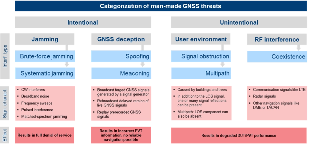
The most critical and common GNSS threats originate from interference signals that occur in the vicinity of a user receiver. Unlike system-inherent threats that originate from GNSS satellites or atmospheric conditions, these threats can be termed as “man-made” and categorized as shown in Figure 1.
Figure 1. Categorization of man-made GNSS threats. Credit: All figures provided by authors.
Jamming can be divided into two types of attacks. Brute-force jamming aims at completely blocking GNSS reception for a receiver by deliberately emitting interference signals like CW interferers, broadband noise or frequency sweeps with very high-power levels. As a result, the carrier-to-noise values will drop below the receiver’s acquisition and/or tracking threshold, and GNSS signals cannot be processed anymore. In contrast to such a simple jamming attack, where the attacker needs to have only basic knowledge about the GNSS signals (e.g. center frequencies and signal bandwidths), systematic jamming is a much more sophisticated attack, which can be further divided into
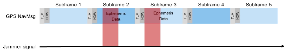
• Intelligent or smart jamming. The objective is to jam only a specific part of the navigation message (e.g. the ephemeris data section), so that the navigation message can never be fully decoded and the receiver will never be able to perform a position fix. All other parts of the navigation message remain unaffected, allowing signal tracking to continue for the receiver. Figure 2 illustrates this attack on the GPS L1 C/A signal.
Figure 2. An intelligent jamming attack performed on a GPS L1 C/A signal.
Smart jamming is much more complicated to implement for an attacker as the jammer must only be active during specific time intervals; this requires that the jammer is somehow synchronized with GNSS/Coordinated Universal Time. Moreover, the attack requires knowledge of the navigation message structure and what information the receiver needs to compute a position. Nevertheless, if done correctly, the attack is rather difficult to detect [1].
• Matched spectrum jamming. The objective is to generate a GNSS-like jammer signal with the same spectral characteristics as the real GNSS signals but without any valuable navigation information (i.e. the navigation message is missing). Matched-spectrum jamming is not straightforward, and to be effective, an attacker must replicate the GNSS signals for multiple visible satellites simultaneously, considering signal characteristics such as pseudo-random noise codes and, ideally, their correct Doppler shifts. In contrast to jamming, GNSS deception techniques aim to force the receiver to compute an incorrect PVT solution, compromising the integrity of GNSS-based navigation. The two basic methods are:
• Meaconing. This rather simple approach is based on rebroadcasting a delayed version of live GNSS signals. This can be realized by using a commercial GNSS repeater. Alternatively, previously recorded actual GNSS signals can be replayed.
• Spoofing. This includes generation and broadcast of forged GNSS signals. This is typically done using a GNSS simulator, but specialized, modified GNSS receivers combined with a transmitting unit can also be used. The simulated signals need to be self-consistent, i.e. a GNSS receiver must be able to compute a PVT solution based on the simulated constellation. Spoofing attacks can be rather simple, e.g. broadcasting high power signals that represent a different location than those of the receiver under attack. The aim is to force the receiver into a reacquisition process, tracking and processing only the fake GNSS signals. More sophisticated spoofing attacks are possible [2], but not discussed in this article.
Additionally, the PVT performance of a GNSS receiver can also be degraded by objects in the vicinity of a GNSS user, causing signal obstruction and reflections from buildings, trees, or the ground. Multipath can cause significant ranging and positioning errors. Multipath effects can hardly be avoided and must be seen as a permanent threat to GNSS signal quality.
Finally, other existing signals and services can interfere with GNSS, either because there is a frequency overlap (in-band interference) or harmonics from other signals fall into the GNSS bands (out-of-band interference). As an example, the upper part of the DME/TACAN band overlaps with a significant portion the GNSS L5 band. The effect of this type of interference on GNSS receiver performance can be analyzed by performing coexistence tests.
RX-Internal Detection and Mitigation Methods
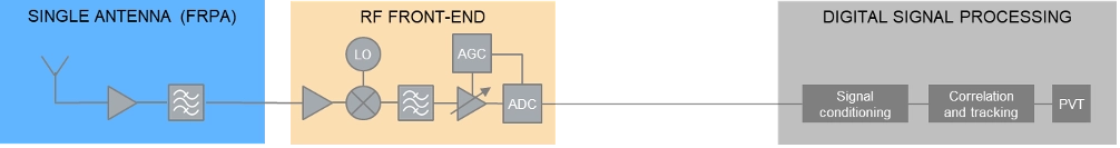
At least some of the threats discussed above can be detected and/or mitigated by the GNSS receiver. The capability of a GNSS receiver to detect and apply countermeasures to threats such as multipath, jamming or spoofing depends on the receiver’s availability of specific features and its basic architecture. Figure 3 shows the basic building blocks of a typical GNSS receiver with a single, fixed reception pattern antenna (FRPA).
Figure 3. Basic architecture of a FRPA receiver
The three basic building blocks are the antenna, the RF front-end and the digital signal processing section. The antenna is responsible for receiving the weak GNSS signals as well as for successive amplifying and band-limiting. It typically features a low noise amplifier (LNA) and a band-pass filter. The signals are then fed to the receiver front-end where the signals are amplified, down-converted to an intermediate frequency and converted to the digital domain. Part of this process is the automatic gain control (AGC) loop; the AGC acts as a variable amplifier, adjusting the power of the incoming signal and keep it constant over time. The sampled and quantized stream of IQ data is then fed to the digital signal processing section, where signal conditioning, acquisition and tracking, and PVT solution computations take place.
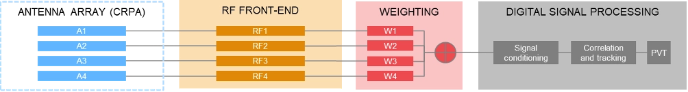
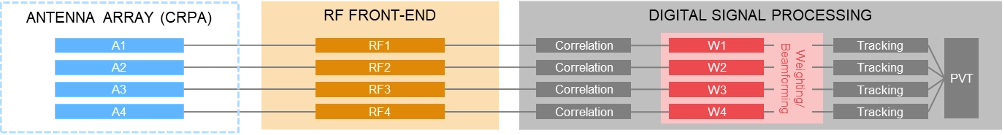
In contrast to using a single antenna with a fixed antenna pattern, some receivers use an adaptive antenna array, also referred to as controlled reception pattern antenna (CRPA). The idea is to weigh the signals received by each element according to dedicated optimization criteria. Typical optimization criteria are to minimize the signal’s output power towards a dedicated direction (“null-steering”), or to maximize the signal to interference or signal to noise ratio (“beamforming”). The underlying receiver architecture is more complex as signal weighting mechanisms must be added to the signal processing chain. These can be integrated before the digital processing block (“pre-correlation”) or implemented as an additional processing step between the correlation and tracking stages in the digital signal processing section (“post-correlation”). Both approaches are very effective in mitigating jamming and spoofing attacks, as they can either form a null in the direction of a strong jammer/spoofer or form beams towards the wanted signals from GNSS satellites, thereby de-weighting any unwanted signals coming from other directions.
Pre-correlation architecture of a 4-channel CRPA receiver
Post-correlation architecture of a 4-channel CRPA receiver
Within the processing chain of a GNSS receiver, there are different approaches and methods to detect and mitigate interfering signals, which are summarized in the following table:
AGC monitoring
●
●
Monitoring of the gain in the AGC loop. A sudden drop of the AGC gain can be an indication of an interfering signal; detection of high-power interferers; low-power spoofing attacks very difficult to detect
Spectrum monitoring
●
●
Detection of interferers and jammers above the noise floor; especially suited for detecting CW interferers. Not suited for the detection of matched-spectrum jammers, spoofers and meaconing attacks as their spectrum is typ. identical to the GNSS spectrum.
Frequency domain adaptive filtering
●
●
Dynamically identifies and suppresses unwanted frequency components (e.g., interference or multipath) by adjusting (notch) filter parameters.
Pulse blanking
●
●
Pulse blanking is a time-domain interference detection and mitigation technique used in GNSS receivers to detect and suppress short-duration, high-power pulses, typically caused by pulse jammers or Radar transmitters. Monitors the incoming signal power in short time windows and “ignores” this signal part in case certain power level thresholds are exceeded. Effective to mitigate pulsed jammers, not suited for multipath mitigation or anti-spoofing measures.
C/N0 monitoring
●
●
Monitoring over time and/or comparison against theoretical max. value; detection of all types of interferers; low-power spoofing attacks very difficult to detect
Time jump detection
●
●
Time jumps (backwards or forwards) are clear indications for meaconing or spoofing attacks.
PVT monitoring, incl. RAIM
●
●
Example: The computed position can be constantly compared against a known reference position. Not possible to distinguish between jamming/spoofing or other environmental effects like multipath. This also includes receiver-autonomous integrity monitoring (RAIM) schemes, that can be considered as a special form of PVT monitoring.
Doppler monitoring
●
●
Compare Doppler against theoretical/geometrical values; monitored Doppler profiles may show irregularities in case of an attack. Difficult to be separated from environmental or atmospheric effects.
CMC monitoring
●
●
„Code minus Carrier“ observable shows irregularities and increased noise in case of an attack. Difficult to be separated from environmental or atmospheric effects.
Signal Quality Monitoring (SQM)
●
●
Sampling of the correlation function using a few correlators; can detect distortions of the correlation function resulting from multipath, jamming or spoofing attacks.
Massive multi-correlator monitoring
●
●
Continuous, high resolution observation of the code/Doppler space. Can be done during signal acquisition and tracking. Can detect multipath, jamming, meaconing and spoofing attacks.
Derived Test Requirements
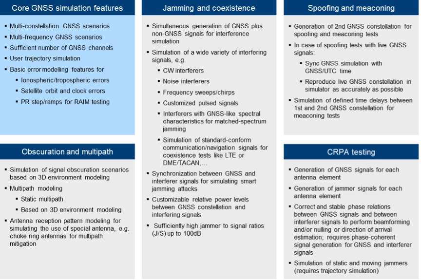
Based on the typical threat signal and attack characteristics, as well as the receiver-internal detection and mitigation methods discussed above, the test and simulation requirements listed in the table below can be derived. In addition to the requirements related to threat simulations (grey background), the table also contains “base requirements” for the simulation of realistic GNSS scenarios (blue background):
Testing: Methods, Setups and Challenges
The test methods, strategies and setups used depend on the architecture of the GNSS receiver being tested, the receiver features that need to be evaluated and the specific testing objectives.
A first categorization can be made by examining the origin of the GNSS signals being used for testing. The signals may come from real GNSS satellites and be used instantly and on-site (live GNSS testing) or recorded, stored, and played back in the lab (record/replay). Alternatively, testing can be done entirely in a lab environment using GNSS simulators. There are also hybrid test methods that will be discussed later in this article. In comparison to using real GNSS signals – either via live testing or the record/replay approach – using GNSS simulators in a lab environment offers significant benefits.
Simulation vs. Live GNSS Testing. One major drawback of using live signals is that the system conditions are often unknown at a given point in time, and – most importantly – they change over time. The locations of the satellites — and thus the geometric conditions — change as the satellites move along their orbits. Errors, such as atmospheric effects, are also time- and location-dependent. One of the most unpredictable error influences is multipath. The magnitude of multipath errors depends on a variety of different parameters, including the number of reflections, the distance between the reflection points and the antenna or the strength of the reflected signal. The latter is determined by the material properties of the reflecting surface. Both the geometric conditions and the material properties of the reflectors change or may change over time – the geometric conditions due to the permanent motion of the satellites and the reflector properties due to meteorological influences like rain, dew, or snow.
As a result, when using live signals, one must expect that the conditions change permanently and unpredictably and will never be the same for two distinct points in time. It is therefore very unlikely that two successive test runs can be performed under identical conditions. Repeatable testing, which is one of the most important test requirements, is impossible when using live GNSS signals.
Well-defined and controlled simulation conditions can only be ensured by using a GNSS simulator. A simulator typically offers fully customizable and repeatable scenarios (i.e., one and the same test scenario) that can be repeated as often as needed, producing the same signals with the same characteristics. Moreover, a simulator is often a more cost-effective and efficient solution, whereas using live signals would be time-consuming, complex, expensive or even impractical (e.g. test of airborne and spaceborne receivers).
The following discussion of typical test setups therefore focuses on the use of signal generators for GNSS testing. In terms of test scenarios, the focus will be on jamming, spoofing and coexistence testing. Testing against multipath influences is not specifically discussed below.
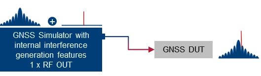
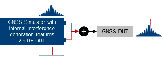
Basic simulator setups. The basic approach for testing against GNSS threats is to combine a “clean” reference GNSS simulation scenario with interfering signals and add the combined signals to the device under test (DUT). This basic concept can be implemented using two separate signal generators or an integrated solution that combines GNSS simulation and threat signal generation in a single instrument. Based on the architecture of the integrated solution (1 RF output vs. multiple RF outputs), GNSS and interfering signals are already combined internally, or GNSS and interfering signals can be fed to different RF outputs and combined with an external combiner before fed to the DUT.
Using two separate signal generators for GNSS threat testing. The interference generator (red) can either be a second GNSS simulator for generating spoofing signals or any other signal generator providing non-GNSS signals for jamming or coexistence tests.
Using a GNSS simulator with integrated interference generation capabilities. The signal generator features 1 RF outputs. GNSS and interfering signals are combined internally. An external combiner is not needed, but the dynamic range between GNSS and interferer (J/S) is usually limited.
Using a GNSS simulator with integrated interference generation capabilities. The signal generator features 2 RF outputs. GNSS and interfering signals fed to individual RF ports and combined externally. This requires an external combiner, but with the benefit that very high J/S ratios can be achieved.
Conducted testing vs. OTA testing. The basic setups introduced above only work if the receiver has dedicated and accessible input connectors to feed the antenna signal to the receiver’s front end. This is sometimes not the case, so that conducted testing is not possible and over-the-air (OTA) tests must be considered. A classic example of such DUTs is mobile phones, where no antenna connector is available, at least not without dismantling the device.
Testing such devices against interfering signals is still possible by using a shield box. The shield box has an RF input to feed in the combined GNSS and interfering signals. The signals are then retransmitted into the inside of the box and the DUT uses its integrated antenna to receive and process the signals coming from the GNSS simulator.
Using a GNSS simulator in combination with a shield box to test GNSS devices with integrated antennas.
OTA GNSS threat simulation using a shield box with 2 RF inputs and 2 transmit antennas. The GNSS signals and the interfering signals are fed separately (uncombined) into the shield box.
An alternative setup is to use a shield box with two RF inputs. In this case, the wanted signals and the interfering signals are not combined externally but are fed to the shield box via separate RF input connectors and transmitted to the GNSS DUT via separate transmit antennas.
Additional aspects and challenges must be considered when performing OTA tests using mobile phones as a GNSS DUT. This includes conducting a proper cold start, removing all preexisting navigation-related information from its memory, and disabling any other sensors that may contribute to computing the phone’s position, including any assisted GNSS services. This is typically not a concern for most standalone GNSS receivers that feature dedicated cold start procedures and usually have no other positioning sensors on board. On the other hand, initiating a real cold start for GNSS modules in mobile phones can be tricky. Just rebooting the phone does not necessarily work, and the availability of dedicated settings also depends on the phone’s operating system (e.g. iOS vs. Android).
Another challenge during OTA testing of mobile phones is how to assess and analyze the impact of any interfering signals on signal acquisition, tracking and positioning. This requires detailed analysis and monitoring features on the mobile phone, which are typically not a standard feature of the phone’s operating system. Specialized GNSS monitoring apps can be used instead. To get access to the data during the test, special screen mirroring apps can be installed on the mobile phone.
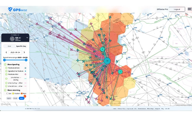
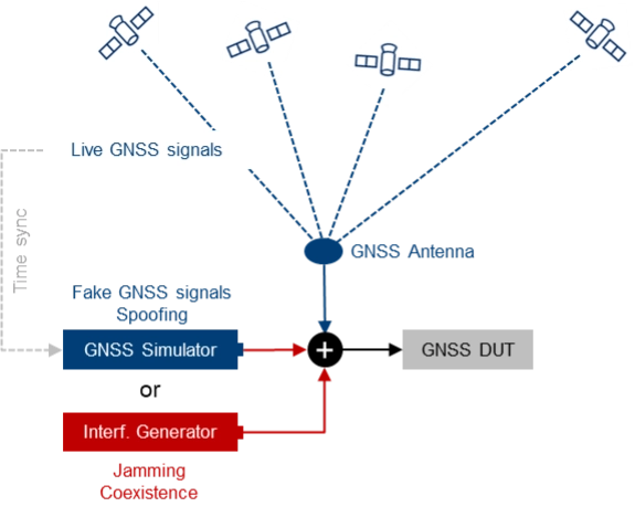
Testing with live signals. GNSS tests may also be performed in combination with live GNSS signals using already existing field infrastructure such as GNSS receivers installed at mobile base stations. A typical use case is to add one or several jamming/spoofing signals, or even an entire (stronger) “spoofing constellation” to an existing “live GNSS constellation” and test how the GNSS receiver reacts to such an attack. The typical test setup is illustrated in Figure 4.
Photo: Figure 4. The receiver’s response to interference is evaluated by introducing jamming or spoofing signals, alongside normal satellite signals using existing field infrastructure. This setup is often used to assess reactions to attacks.
This approach may be a good alternative to simulating everything with a GNSS simulator, as much more HW, i.e., more GNSS channels and more RF paths, are required with a simulator-internal approach. On the other hand, there are also some challenges associated with this test method, e.g., the signal generators, which need to be operated in a field environment. Moreover, for more sophisticated spoofing attacks, a prerequisite is the capability to time-synchronize the GNSS simulation with the live GNSS constellation.
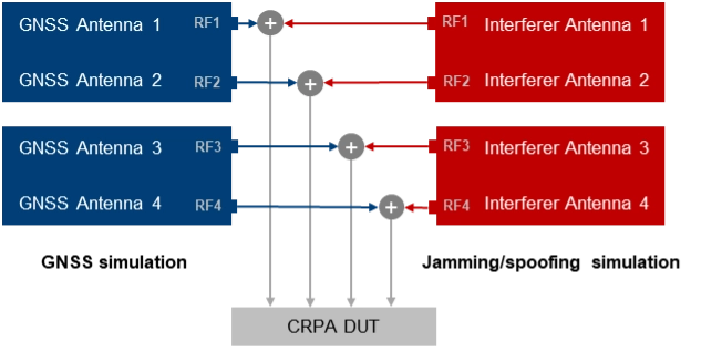
CRPA testing. For testing GNSS receivers with multiple antenna inputs, particularly CRPA systems, several RF sources/paths need to be combined and synchronized. The following illustration shows a possible setup for testing a 4-channel CRPA receiver against jamming or spoofing attacks. It is based on the 2-path architecture introduced above. It consists of two signal generators for generating GNSS signals for each antenna (left part of the setup) and two signal generators for generating the jammer/spoofer signals (right part of the setup). GNSS and interfering signals are combined per antenna element and fed to the RF inputs of the CRPA receiver under test.
For CRPA testing, generating phase-coherent signals is a must, i.e., it must be ensured that the phase relations between the GNSS signals and between the interfering signals represent the actual geometrical conditions and, above all, remain consistent throughout the simulation. To achieve this, a common LO signal needs to be used for generating the GNSS and interferer signals in all signal paths.
Another challenge is related to calibration. To correctly simulate the directions of the satellite signals and the interference signals, the test system must be calibrated at the RF interface to the DUT with respect to amplitude, phase and propagation time. This means that the amplitude, phase and propagation time differences between the individual RF paths, resulting for example from cables orRF components, must be compensated.
Rohde & Schwarz Solution
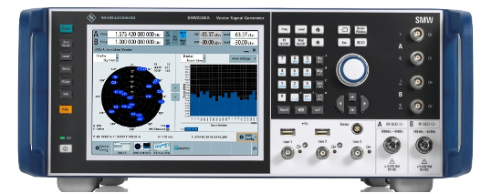
With GNSS test solutions from Rohde & Schwarz, all the relevant requirements for testing GNSS receivers against GNSS threats can be addressed. Available test solutions range from simple, single-channel, waveform-based signal generation with limited simulation time up to multi-frequency, multi-constellation GNSS simulators with 2 RF outputs, hundreds of GNSS channels and internal threat simulation capabilities, including non-GNSS signals for jamming and coexistence tests. For these advanced GNSS tests, the R&SSMW200A high-end vector signal generator is the ideal choice. It can be equipped with a multitude of GNSS options and feature sets.
Photo: Testing against GNSS threats with the R&S SMW200A
Jammer simulation. There are several ways to generate jamming and coexistence signals with Rohde & Schwarz signal generators in general and especially with the R&SSMW200A. Simple interference signals like noise or a CW interferer can be generated by using an optional integrated noise generator. For coexistence testing, the instrument can be equipped with signal generation capabilities for various standard-conforming communication signals, such as LTE. Customized interferer signals in the form of waveform files can be created by external software tools like MATLAB or Python and replayed by the instrument.
Customized jamming signal as well as entire jamming and coexistence scenarios can also be created using the R&SPulse Sequencer. The software allows to generate typical simple GNSS jamming signals like CW interferer, frequency sweeps, or pulsed interferers, but also complex jamming scenarios with consideration of moving interference sources and moving GNSS receivers, user-defined antenna patterns and scans. Depending on the signal characteristics, the jammer and receiver positions and the antenna arrangement, the software calculates the correct amplitude, phase angle and signal propagation times for the jamming signals.
Further reading
[1] Curran, James T. et. al. (2017): A look at the Threat of Systematic Jamming of GNSS, InsideGNSS, September/October 2017
[2] Dovis, Fabio et. al. (2015): GNSS Interference Threats and Countermeasures, GNSS Technology and Application Series, Artech House, 2015
Throw a dart at a map of Tennessee. You will probably hit somewhere that is growing. Nashville’s outskirts are projected to add a quarter to their population in the next 15 years. The Ford Motor Company has begun construction on the BlueOval City manufacturing plant outside of Memphis. A multibillion-dollar uranium enrichment facility has broken ground in the Knoxville exurbs.
Tennessee growing at double the rate of the rest of the U.S. does not surprise anyone who issues residential building permits in the state. Inspectors at the Tennessee Department of Environment and Conservation (TDEC) saw requests for subsurface sewage disposal system services jump 18% in one year. “It’s a monumental, staggering rate to grow,” said Steve Owens, the TDEC environmental consultant tasked with expediting service delivery across the state.
Owens, a meteorologist by training, hydrologist by virtue, and self-taught geographic information system (GIS) engineer by practice, streamlined the work of TDEC inspectors with enterprise GIS technology. With it, a team of fewer than 100 inspectors processed over 23,000 requests last year in Tennessee’s rural fringe communities.
Designing a System Around How Inspectors Work
About one in five Americans lives in a home that relies on a septic system. They are built in remote areas too far to connect to municipal sewage systems, which happen to be the places where Tennessee is growing the fastest. High demand for housing created a sense of urgency to issue permits as swiftly — and as safely — as possible.
Owens spent his early career in a truck as a septic permit inspector. “It’s hard work,” he said from his Memphis office. “You’re dealing with outdoor conditions all day and you’re never working fast enough.”
Inspectors often eat lunch in their trucks while driving to their next site. The septic systems that they design, permit and inspect treat wastewater from homes and businesses. These systems must be well suited to the specific soil conditions of the land to work properly. When evaluating proposed subdivisions, inspectors conduct a range of fieldwork assessments — such as soil profiles, percolation data, and absorption rates — all while answering calls from the public.
Inspectors assess whether a new septic drain field meets state regulations before the property can be occupied.
A malfunctioning or ill-fitted septic system can pollute wells of drinking water and springs. Foul-smelling sewage can pool on the surface, creating a breeding ground for parasites, mosquitoes and other vectors that can spread pathogens to neighbors and pets.
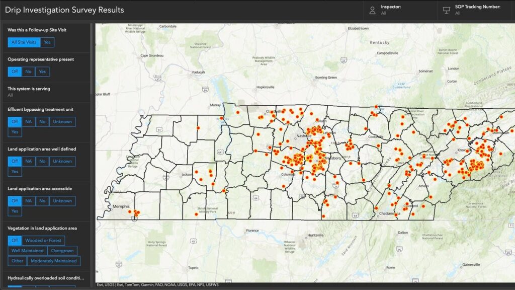
A June 2024 TDEC audit of drip dispersal systems documented more than 400 site visits in a short time frame. Inspectors used an ArcGIS enterprise program to compare standard observations and record site-specific notes and photographs at each site. Results are filtered and displayed on an interactive map.
The audit represents a fraction of the work that TDEC permit inspectors do. Complaint investigations, repair designs, and expansion assessments are among the 13 different types of services inspectors deliver each day. To modernize, Owens configured an enterprise GIS to manage the full scope of operational data for those services—from how residents make requests, to how inspectors execute the work and get documentation to the customer, to how management reports progress.
“It’s different from the typical mapping and analysis you might associate with GIS,” Owens said. “We’re utilizing ArcGIS Survey123 and ArcGIS Dashboards to create an efficient ecosystem for what we do with our work and how to get that work out to the public.”
The drip dispersal system audit documented all results from more than 400 site visits.
A “Flintstones to Jetsons” Digital Transformation
As recently as seven years ago, Tennessee septic permit data existed entirely on paper. Pulling a permit meant driving to a state office in the county seat and making photocopies. Digitization came with an announcement from the governor that made headlines across the state. Trucks hauled away filing cabinets full of septic records, and technicians scanned their contents to create a FileNet public document system of record. “We have gone from Flintstones to Jetsons in the last decade,” Owens said.
In the past, permit requests came to TDEC inspectors as a list of addresses and contact information. Inspectors started each day punching addresses into online mapping sites, guessing at an efficient route. Their days ended back at the office to log their time, update templates, and input data into various spreadsheets.
In high-growth counties, where multiple inspectors collaborate to tackle a significant workload, they often duplicated efforts. “It would not be uncommon for someone to go out to a site on Wednesday, and the next guy would go out there on Friday and not know the work had already been done,” Owens said.
Owens considered the extensive manual processes involved in permit inspections. Having used GIS technology for environmental impact assessments for other TDEC projects, he knew the work could be automated. “We had already been using mobile GIS tools for some time at that point, so staff were used to it,” Owens explained. “I thought we could utilize a lot of the tools that Esri already has built in and customize it a little bit to meet our needs.”
Conversations with TDEC managers confirmed the hunch. Inspectors were spending up to two hours each day planning their routes and logging what they had done. “It ended up being somewhere about 34,000 hours a calendar year just figuring out where we’re going and tracking what we do,” Owens said.
The project to upgrade the workflow with GIS would pay for itself in eight months if they could cut the tracking and logging time in half.
Automating Data Editing and Management Workflows
Owens envisioned a system that would link service requests to jobsite workflows. He designed configurable applications for inspectors to use for data collection. Permit and inspection data would integrate into an enterprise geodatabase that serves as a source of truth for TDEC septic service requests. The database would sync to the public document viewer.
In the new GIS-based system, residents and developers make permit service requests by filling out an online application. The system then locates the request, assigns an inspector, and sends the appropriate form that guides the inspection work. Inspectors check the boxes, record the test results, upload photos and drawings, and issue letters and certificates—all from tablets in the field.
Inspections in the queue now appear on a shared map.
Submitting the completed permit or inspection through ArcGIS Survey123 generates PDFs that automatically go to the applicant, TDEC staff, and the database that syncs to the public site.
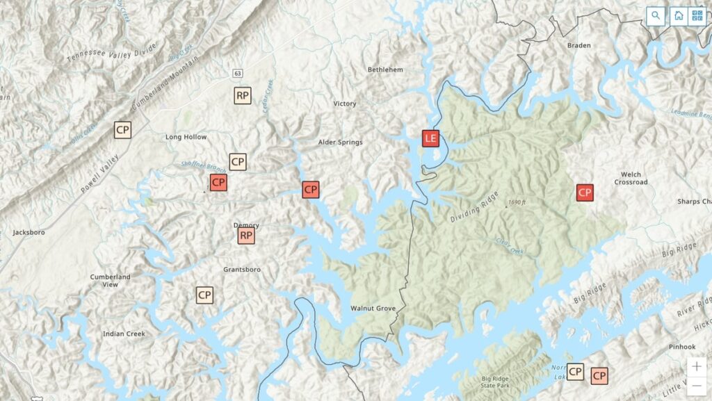
“The real gem is for staff to be able to plan their day by using a map instead of entering all that data into online map tools and seeing what they come up with for their route,” Owens said. The map is part of a real-time operations dashboard with hundreds of requests dotted across Tennessee.
Points colored with darker hues alert inspectors to older requests—fees are waived if they are not completed within 45 days. All the related information—requester contact, location data, violations, resolutions, test results, and historical records—is organized by location. “This used to be done in spreadsheets and file cabinets so it’s a huge time-saver,” Owens said.
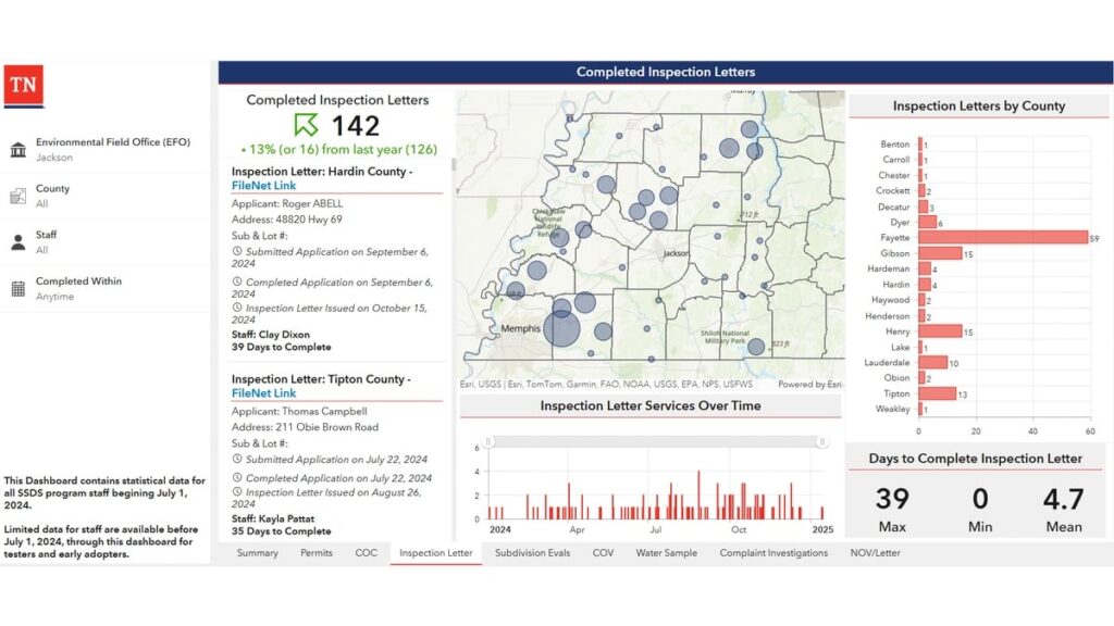
TDEC staff now have a completed inspection report that details their work across the state and allows managers to keep an eye on the completion rate.
When management sees clusters of requests on the map, they know it is time to reallocate resources. “They can pull in inspectors from other counties to get the work done, and then go back to normal workload,” Owens added.
Management watches a splash page that tabulates completed work to keep a pulse on field staff and avoid backlogs. They can drill down on how long specific tasks are taking, and view performance metrics for individual staff members. They pay close attention to the average number of days it takes to issue permits. If the times go up, they have the data to bring to the budget office to justify hiring more inspectors.
Amid Tennessee’s building boom, officials face intense pressure to keep pace and deliver high-quality results. Modernizing their permitting and inspection system has provided TDEC with tangible efficiency gains to present to legislators and the public.
“This was a major investment in our division, and we want to let them know that, ‘we hear you,’” Owens said. “We can show how much work that we have done to address those concerns, and the output speaks for itself.”
This year, TDEC was awarded honorable mention by the Environmental Council of the States (ECOS) in the State Innovation category for their septic permitting modernization project.
Safran Electronics & Defense‘s Skydel GNSS simulation platform is now fully certified to support simulation of Xona Space Systems’ low-Earth orbit positioning, navigation and timing (LEO-PNT) signal, Pulsar.
According to the companies, this certification is the culmination of a rigorous multi-phase validation program jointly led by Safran and Xona engineering teams. It underscores Safran’s commitment to advancing robust, high-fidelity testing for next-generation LEO-PNT services. With this milestone, engineers can now use Skydel to evaluate Pulsar’s performance in environments that reflect real-world complexity, interference and operational demands.
Skydel now simulates Xona’s Pulsar X1 signals, delivering centimeter-level precision, 100x signal strength and enhanced resilience — capabilities that Pulsar will soon bring to orbit.
“With Skydel-powered simulators certified for Pulsar X1, our customers have more possibilities than ever,” said Pierre-Marie Le Veel, program director of PNT simulation at Safran Electronics & Defense. “They can test LEO and legacy constellations side by side, introduce complex interference, and explore entirely new scenario combinations — all from a single, flexible platform. This is a major step forward in enabling engineers to push the boundaries of GNSS testing.”
Beyond accuracy, Skydel enables advanced resilience testing, including jamming, spoofing and other NAVWAR threats. Its modular, future-ready architecture ensures seamless integration of new Pulsar signal types and constellation updates, offering the agility needed to keep pace with the evolving LEO PNT landscape and demands for trusted, high-integrity PNT.
“Validation is the bridge between innovation and trust,” said Tyler Reid, CTO of Xona. “By replicating Pulsar at full fidelity, Skydel empowers engineers to design and validate solutions for the most demanding navigation and timing challenges — without waiting for on-orbit availability.”
Skydel’s certified Pulsar simulation capability is available now to partners and customers worldwide.
Saab will divest Saab TransponderTech AB, which is being acquired by FLIR Systems AB, a subsidiary of Teledyne Technologies Inc. Completion of the divestment is subject to certain conditions that are expected to be fulfilled by the end of 2025.
TransponderTech is a leader in Safety Of Life At Sea (SOLAS)-certified communications and navigation solutions for commercial maritime, military and airborne applications.
TransponderTech’s solutions include advanced GNSS technologies, which FLIR expects to integrate into its commercial maritime products. Based in Linköping, Sweden, TransponderTech also provides Automatic Identification System (AIS) and VHF Data Exchange System (VDES) solutions. The company is known for high-quality products that perform reliably in challenging conditions.
“Integrating TransponderTech’s advanced AIS, VDES and GNSS technologies into our commercial maritime products strengthens our ability to deliver secure, reliable and globally connected navigation solutions,” said Grégoire Outters, vice president of Teledyne FLIR Maritime and Raymarine. “This acquisition will directly enhance our safety, efficiency and operational reach of our customers at sea.”
The divestment is in line with Saab’s strategy to increase its focus on core areas of its business and, upon closing, Saab will divest 100 percent of its shares in Saab TransponderTech AB.
Quectel Wireless Solutions has introduced four new GNSS antennas. The new antennas include:
The YFGD000AA high-precision, low-profile antenna which covers all GNSS bands
The YFGD000BA, optimized for triple-band solutions in GNSS L1, L2 and L5 bands
The YFGN000H1AC high-precision, lightweight antenna that again covers all GNSS bands
The YEGT010W1AM, designed for general-purpose reception in non-precision applications.
Quectel’s triple-band and all-band antennas are built to maximize performance with the latest generation of RTK GNSS modules. These include the LC29H dual-band module, designed for cost-sensitive yet precision-critical applications; the LG290P industrial-grade module, delivering centimetre-level accuracy with RTK fix times under five seconds; and the flagship LG580P, which adds L6 support and dual-antenna heading, making it suitable for ADAS, robotics and autonomous systems.
Complementing the hardware, Quectel’s global RTK correction service leverages a network of more than 21,000 base stations to provide consistent centimeter-level accuracy worldwide, ensuring seamless coverage across Asia, Europe and North America, and enabling scalability for industries such as agriculture, logistics and automotive.
The YFGD000AA is a high-performance multi-band active GNSS antenna designed for professional applications requiring ultra-precise positioning across L1, L2, L5, L6 and L-Band frequencies (1164–1300 MHz and 1525–1606 MHz). With dimensions of 78.6mm x 75.6mm x 16.2mm and a screw mounting, the antenna is suitable for vehicular or fixed installations and operates in the -40 °C to +85 °C temperature range. Combining exceptional signal sensitivity with rugged durability, this antenna is engineered for mission-critical deployments in autonomous systems, geodetic surveying and high-accuracy navigation. It is RoHS, REACH and POPS compliant.
The YFGD000BA offers similar capabilities to the YFGD000AA but has been developed to support professional applications with ultra-precise positioning needs across L1, L2 and L5 bands (1164–1238 MHz and 1559–1606 MHz). It shares dimensions, operating temperature range and mounting options with the YFGD000AA and is also RoHS, REACH and POPs compliant. Both the YFGD000AA and YFGD000BA can support high-precision RTK despite their compact size.
The YFGN000H1AC is a high-precision antenna with a higher profile than the YFGD000AA and YFGD000BA but with greater performance and lighter weight of 62g. The antenna covers all GNSS bands, ensuring worldwide compatibility. It delivers 35 ±4 dB gain with a low noise figure of ≤4 dB, making it suitable for weak-signal environments like urban canyons or dense foliage. With a diameter of 122mm and height of 22.5mm, the antenna features a screw mounting so it can be attached to vehicles or fixed installations. It operates in –40 °C to +85 °C temperature range and is RoHS and REACH compliant. Should customers require it, Quectel can supply enclosures to convert the antenna from an internal to external set up.
Finally, the YEGT010W1AM is a GNSS rubber external antenna with a diameter of 10.22 mm and height of 69.5 mm. This ultra-wide-band GNSS antenna provides broad coverage from 1559–1606 MHz and is terminated with an SMA male connector. With omnidirectional capability and linear polarization, YEGT010W1AM is designed for general-purpose reception in non-precision applications, especially where signal direction varies.
The terminal mount design, with a compact, rugged form factor makes it easy to install on gateways, routers or tracking devices in protected environments. Operating in the –40 °C to +85 °C temperature range, the antenna weighs 8.9g and is RoHS compliant. In addition, the antenna’s universal joint design allows customers to easily adjust the polarization direction, helping to mitigate the angle sensitivity commonly associated with linearly polarized antennas in real-world applications, therefore enhancing overall signal stability.
In addition to the antennas, Quectel provides comprehensive antenna design support services such as simulation, testing and manufacturing for custom antenna solutions to meet developers’ and designers’ specific application needs.
Quantum technologies may offer a solution to GPS jamming and spoofing, according to the University of Chicago. Already, prototypes are being tested of a suite of sensor-based techniques that do not rely on satellite signals.
GPS jamming and spoofing have emerged as growing threats in recent years, according to the Chicago Quantum Exchange, based at the university. In 2024 alone, more than 1,000 commercial flights per day were affected by GPS spoofing, especially while flying through regions like the Middle East and Eastern Europe.
During these incidents, in-flight instruments show pilots that their aircraft is flying higher or lower than they truly are or that they are miles off their actual location. In maritime settings, spoofed GPS signals have even caused ships to veer off course or run aground. These are not isolated glitches but the result of deliberate electronic warfare tactics.
Corporate partners of the Chicago Quantum Exchange, including Boeing, Infleqtion and SandboxAQ, are among those developing applications. The CQE is a hub that connects leading universities, national labs, and industry partners to advance quantum technology.
“Governments and the commercial industry are in dire need of this technology,” said Ken Devine, senior product manager for quantum navigation at SandboxAQ. “The geopolitical issues happening across the world, and the ramp up in both jamming and spoofing — Russia, Ukraine, the Middle East, Israel, Iran — everyone’s getting super disruptive, and that’s not going to go away anytime soon. Everyone is saying, ‘We basically need this yesterday.’”
In May 2023, SandboxAQ completed the first of many flight tests for the United States Air Force and its commercial aviation partners, including two major Air Force exercises that year.
In 2024, Boeing completed the world’s first recorded flight using multiple quantum navigation systems, testing the ability of these sensors to navigate across the central U.S. for four hours without GPS.
The Boeing test incorporated two different technologies. The first is a magnetic field-based navigation system called AQNav from SandboxAQ, It uses map matching, though the map that they use is of the Earth’s crustal magnetic field rather than terrain. Infleqtion is investigating both techniques. The second is an inertial navigation system from quantum sensing technology company AOSense.
Jay Lowell, principal senior technical fellow at Boeing, said it was vital to consider “whether and how” the different technologies could be used together. “Maybe that means a tradeoff of performance between sensors in moments where one struggles and the other’s strong,” Lowell said. “Fundamentally, it means we just need to understand whether their combined data is better than either one alone.”
Detecting tiny changes
Inertial navigation depends on accelerometers and gyroscopes — which respectively measure acceleration and rotation — to measure movement. An inertial sensor tracks how an object moves from a known starting point by recording changes in its speed and direction.
While basic accelerometers are common in smartphones and fitness trackers, quantum inertial sensors can detect changes in motion down to the femtometer — less than the width of an atom — making them extraordinarily precise. Inertial sensors have applications in space-based technology, since they do not need maps or fixed points to navigate.
Infleqtion recently completed commercial flight trials of inertial-based quantum navigation in the United Kingdom and plans to conduct tests in the U.S. as well. Infleqtion’s Chicago office is also developing an AI-powered tool called SAPIENT that won first place in the U.S. Army’s xTechScalable competition.
“[SAPIENT] is focusing on the software side, taking the outputs of multiple kinds of sensors and stitching them all together with AI to provide a more robust navigation signal,” said Pranav Gokhale, general manager of computing at Infleqtion. “There is a big gap between an inertial measurement unit and a full inertial navigation system, so we’re using AI to fill that gap.”
Alternatively, magnetic navigation, or MagNav, works much like terrain-following radar, comparing real-time sensor data to a known map to pinpoint location.
But instead of elevation, the aircraft senses subtle magnetic fluctuations in the Earth’s crust — variations caused by geology, mineral deposits and even human infrastructure — and compares its measurements to a corresponding map of that field.
Scientists believe that birds can use their ability to sense the Earth’s magnetic field to navigate in a similar way. Magnetic field maps of the globe are frequently done for mineral, oil and gas surveys, as small anomalies in the field can indicate resources underground. But there are areas where high-resolution maps can be hard to come by.
“Map quality in the region you’re going to is definitely a factor that gets plugged into how well magnetic navigation can perform,” Devine said.
He identified a list of other key variables, such as the type of aircraft being used, plus its altitude and speed, as additional points of consideration for MagNav technology. At the same time, he said the importance of these tools is likely to grow as electronic warfare strategies become even more entrenched.
“We’ve validated that we can do real-time navigation with this technology,” Devine said. “And that’s huge, because the need for it is only going to increase.”
Intellian Technologies Inc., a leading global provider of satellite communication antennas and ground gateway solutions, and Eutelsat, a GEO-LEO operator in satellite communications, have developed a portable, fully integrated military-grade Manpack for Eutelsat’s OneWeb low-Earth orbit (LEO) network.
With auto detected resilient GNSS (R-GNSS), the military-grade unit enables external support of an alternative positioning, navigation and timing (Alt-PNT) to ensure operation in GPS-denied environments.
Developed for defense and government, the unit provides the uninterrupted, dependable Eutelsat OneWeb LEO connectivity. It was created to address the urgent need for next-generation LEO capabilities within the broader military satellite communications domain.
Designed for rapid deployment, the Manpack is small and light to fit a standard military rucksack. It features one-touch network acquisition for immediate operation even in demanding and high-pressure conflict regions. It is optimized for low power consumption to maximize mission duration for up to five hours on external batteries depending on usage.
Built to battlefield-ready specifications, the Manpack is designed for Ingress Protection (IP67), as well as the U.S. Military Standards for Environmental Engineering (MIL-STD-810H) and Electromagnetic Compatibility (MIL-STD-461). This ensures exceptional durability for Communications-On-The-Pause (COTP) to personnel on front lines and mission-critical operations.