GNSS have been with us for more than 30 years, giving rise to a wealth of positioning and navigation technologies for military, civilian, and consumer use. Today, we’re entering a new era of experimentation and innovation in satellite and hybrid positioning. In turn, this drives new test challenges and introduces an ever wider group of engineers to the art and science of GNSS test.
Where Is the Testing Panacea? I am sometimes asked, “What is the best way of testing a GPS receiver?” — as if there existed some laboratory panacea to all GNSS test and characterization woes. Well, there is a saying, “There are horses for courses,” meaning what performs well in one situation may not deliver in another, and nowhere is this more true than in the field of GNSS test. Not only is there a wide range of different test equipment available, but there are no universally applicable test objectives, test methods, or parameter definitions, in exactly the same way as there is not one universally applicable GNSS receiver. Just as the rapid time-to-first-fix of an automotive receiver may be less relevant in a maritime environment, so different test approaches have their place.
A Systematic Approach. If there is one thing, it is this: be systematic in your test design. Consider the purpose of the test, the test conditions, and the measurements you plan to take, and be wary of generic tests that may not achieve your objectives.
Equipment. A wide range of GNSS testing equipment is available, ranging from basic single-constellation RF simulators to highly configurable, multi-GNSS constellation simulators. Single-channel, multi-channel, and record and playback systems all have their place, and to get the best results in the fastest time, it’s essential to choose the kit that’s right for the kind of testing you need to do.
Vulnerability, Fidelity, Integrity, and Time Travel. More and more, receivers need to be tested for their vulnerability to interference, jamming, and spoofing. As GNSS-derived position and time become more ubiquitous, so the motivation for confounding the system grows. This has a double impact on test.
First, performance requirements around vulnerability may be introduced, with tests to match. Second, and perhaps less obvious, is the way in which this concern is reflected in the receiver’s design and potential rejection of the laboratory test signal. Yes, I mean receivers getting more fussy about the signals they lock onto. Anyone who has tested a receiver with an out-of-date recording or simulation scenario will have experienced a receiver refusing to track a satellite showing a time and date prior to its firmware release date. The receiver, discounting time travel, knows there has to be something wrong with a satellite showing a date before it was born. With the risk of spoofing, receivers will only get more picky and likely to reject poorly simulated signals. To avoid such effects, it is important to have very high integrity and fidelity in any simulator system. Getting these details right is not esoteric, but is essential to allow the proper attribution of any problems observed and if test results are to have any meaning.
Conclusion. Be systematic in your approach to test; beware the universal and generic; “good enough,” it rarely is.
Steve Hickling is lead product manager for Spirent’s GNSS simulator business and is based at the factory in Paignton, England. Previously he held a variety of marketing, technical, and management roles in the telecoms and optical components industries. He holds a bachelor of science degree in physics and electronic engineering from Birmingham University, an MBA from Open University Business School, and a post-graduate diploma from the Chartered Institute of Marketing.
By Pierre Nemry and Jean-Marie Sleewaegen, Septentrio Satellite Navigation
Today’s customers ask for high-accuracy positioning everywhere, even in the most demanding environments. The time is long gone that the only requirement for a receiver was to track GPS L1 and L2 signals in open-sky conditions. State-of-the-art receivers operate in increasingly difficult conditions, cope with local radio-frequency interference, survive non-nominal signal transmissions, decode differential corrections from potentially untrusted networks — and more!
Difficult real-life operating conditions are typically not addressed in textbooks or in the specialized literature, and yet they constitute the real challenge faced by receiver manufacturers. Most modern GNSS receivers will perform equally well in nominal conditions, or when subjected to nominally degraded conditions such as the ones that correspond to standard multipath models. However, the true quality of a GNSS receiver reveals itself in the environment in which it is intended to be used.
In view of this, a GNSS manufacturer’s testing revolves around three main pillars:
◾ identifying the conditions and difficulties encountered in the environment of the intended use,
◾ defining the relevant test cases, and
◾ maintaining the test-case database for regression testing.
In developing new receiver functionality, it is important to involve key stakeholders to comprehend the applications in which the feature will be used and the distinctive environment in which the receiver will function. For example, before releasing the precise-point-positioning (PPP) engine for the AsteRx2eL, we conducted a field-test campaign lasting a full month on a ship used for dredging work on the River Thames and in the English Channel. This enabled engineers to capture different types of sea-wave frequency and amplitude, assess multipath and signal artifacts, and characterize PPP correction data-link quality.
Most importantly, we immersed the team in the end-user environment, on a work boat and not simply in a test setup for that purpose. As another example, in testing our integrated INS/GNSS AsteRxi receiver for locating straddle carriers in a container terminal, we spent months collecting data with the terminal operator. This was necessary to understand the specificities of a port environment, where large metal structures (shore cranes, container reach-stackers, docked ships) significantly impair signal reception.
Furthermore, the close collaboration between the GNSS specialist, the system integrator, and the terminal owner was essential to confirm everything worked properly as a system. In both examples, in situ testing provide invaluable insight into the operating conditions the receivers have to deal with, much surpassing the possibilities of a standard test on a simulator or during an occasional field trip.
Once an anomaly or an unusual condition has been identified in the field, the next step is to reproduce it in the lab. This involves a thorough understanding of the root cause of the issue and leveraging the lab environment to reproduce it in the most efficient way. Abnormalities may be purely data-centric or algorithmic, and the best approach to investigate and test them would be software-based. For example, issues with non-compliance to the satellite interface control document or irregularities in the differential correction stream are typically addressed at software level, the input being a log file containing GNSS observables, navigation bits, and differential corrections.
Other issues are preferably reproduced by simulators, for example those linked to receiver motion, or those associated to a specific constellation status or location-dependent problems. Finally, certain complicated conditions do not lend themselves to being treated by simulation. For example, the diffraction pattern that appears at the entrance of a tunnel is hard to represent using standard simulator scenarios. For these circumstances, being able to record and play back the complete RF environment is fundamental.
Over the years, GNSS receiver manufacturers inventoried numerous cases they encountered in the field with customers or during their own testing. For each case, once it has been modeled and can be reproduced in the lab, it is essential to keep it current. As software evolves and the development team changes, the danger exists that over time, the modifications addressing a dysfunctional situation get lost, and the same problem is reintroduced. This is especially the case for conditions that do not occur frequently, or do not happen in a systematic way. Good examples are the GLONASS frequency changes, which arise in an unpredictable way, making it very difficult for the receiver designer to properly anticipate. This stresses the importance of regression testing. It is not enough to model all intricate circumstances for simulation, or to store field-recorded RF samples to replay later. It is essential that the conditions of all previously encountered incidents be recreated and regularly tested in an automated way, to maintain and guarantee product integrity.
The coverage of an automated regression test system must range from the simplest sanity check of the reply-to-user commands to the complete characterization of the positioning performance, tracking noise, acquisition sensitivity, or interference rejection. Every night in our test system, positioning algorithms including all recent changes are fed with thousands of hours of GNSS data, and their output compared to expected results to flag any degradation. Next to the algorithmic tests, hardware-in-the-loop tests are executed on a continuous basis using live signals, constellation simulators, and RF replay systems, with the signals being split and injected in parallel into all our receiver models. Such a fully automated test system ensures that any regression is found in a timely manner, while the developer is concentrated on new designs, and that a recurring problem can be spotted immediately. The test-case database is a valuable asset and an essential piece of a GNSS company’s intellectual property. It evolves continuously as new challenges get detected or come to the attention of a caring customer-support team. Developing and maintaining this database and all the associated automated tests is a cornerstone of GNSS testing.
Wealth, breadth, and depth. That’s what this issue brings you, in signal simulation- and testing-related content. Unfortunately, the wealth on offer has to large extent elbowed out our two news sections, The Business and The System. The former is given short shrift in this issue and the latter even shorter herewith, in pithy precis with website shortcuts. And our apologies.
Let’s all remember, brevity is the soul of wit.
GPS III Flexible Signal Generator. With completion of the Delta Preliminary Design Review for the GPS III satellites, Lockheed Martin and the U.S. Air Force announced that “an innovative new waveform generator permits the addition of new navigation signals after launch to upgrade the constellation without the need to launch new satellites.”
IGS Real-Time Service. The International GNSS Service, a worldwide federation of agencies involved in high-precision GNSS applications, announced the launch of its Real-Time Service (RTS). The RTS is a global-scale GNSS orbit and clock correction service that enables real-time precise point positioning and related applications requiring access to IGS low-latency products. The RTS is offered in beta as a GPS-only service for the development and testing of applications.
QZSS Will Grow to Four. The Japanese government has ordered three navigation satellites from Mitsubishi Electric Corp. to expand the Quasi-Zenith Satellite System, currently orbiting the sole Michibiki. QZSS augments GPS navigation signals for users in the Asia-Pacific region. NEC Corporation has been awarded a contract for the QZSS ground control segment.
Real-Time PPP with Galileo. Fugro Seastar AS achieved this task within a week of all four Galileo satellites being activated. Fugro is now generating Galileo orbit and clock corrections, which can be used in conjunction with the Fugro G2 decimeter-level corrections associated with its GPS/GLONASS PPP service.
BeiDou Ground System Approved. The BeiDou Ground-Based Enhancement System (BGBES), a network of 30 ground stations, an operating system, and a precision positioning system, was approved by a Chinese government evaluation committee. The system is expected to improve BDS positioning accuracy to 2 centimeters horizontal and 5 centimeters vertical via tri-band real-time precision positioning technology, and to 1.5 meters with single-frequency differential navigation technology.
CNAV Test on GPS L2C and L5. The U.S. Air Force Space Command announced that CNAV capabilities on the GPS L2C and L5 signals will be tested in June. The civilian navigation message to be carried by modernized GPS will have similar data to the existing NAV message, but its structure will be different, with increased message bandwidth for greater information density. L2C and L5 users and receiver manufacturers are encouraged to review the test plan, provide comments, and participate in the evaluation process.
GPS at the Smithsonian. Brad Parkinson’s presentation, “GPS for Humanity — The Stealth Utility,” is now available as video on UStream.The talk helped introduce the new Smithsonian National Air and Space Museum exhibit, “Time and Navigation: The Untold Story of Getting from Here to There,” which is now open and free to the public in Washington, D.C.
Years ago when ArcView II first hit the street, I had one of those “eureka” moments at the Esri User Conference Poster Session. I saw a poster of the human circulatory system created with ArcView Network Analyst. I did a double take at first because until then all previous network maps I saw were road or stream networks. I thought, of course, a network is a network regardless of size or composition.
I’m having the same kind of reality adjustment with the technologies demonstrated at the 2013 Consumer Electronics Show, held in Las Vegas in January. It seems like technologies are overlapping in ways we don’t expect — computers, electronics, CAD/CAM, GIS, topology, BIM, medicine, and manufacturing to name a few. Technology paths are no longer direct and simple, but complex and interconnected. With more than 3,000 exhibitors at CES, it’s hard to make sense of it all, so I’ll focus on technologies that may potentially have impact on our GIS community and how we evolve.
Displays
UHD and OLED
Big screen TV’s are always the show grabbers at CES, and there were several examples of OLED (organic light emitting diode) and 4K UHD (Ultra High Definition) TVs from Sony and Samsung that had four times the resolution of current HD TVs — some as big as 110 inches. I don’t believe that UHDs will make a big difference in our ability to present GIS data or imagery, but OLED technology may. Two years ago I wrote about the promise of OLED displays. OLEDs would be big, bright, inexpensive and energy efficient, since the light comes from the OLEDs and not from a light panel behind an LCD screen, like current flat-panel displays. OLEDs are now available, but as you would expect, this new technology is not cheap. However, most experts agree that OLED displays will eventually get to be very cheap. (See my July 2010 OLED article for more details.)
PaperTab is a flexible paper tablet PC.
PaperTab
Related technology from Plastic Logic was PaperTab, a completely flexible “paper tablet PC.” PaperTab combines the feel of paper with the speed and convenience of digital imagery. It looks very much like the Harry Potter Daily Prophet moving pictures newspaper. Work is underway to ultimately work in OLED technology to produce large, cheap roll-up screens that would be very bright and eliminate the need for LCD projectors.
An Oculus virtual reality prototype fascinates a viewer.
Oculus Virtual Reality
Oculus VR is so new that only prototype units are being shipped to software developers. The combination of stereoscopic vision and very effective head-tracking sensors make this device possible. Unlike other VR displays, Oculus has very high resolution plus a 110-degree field of view. 110 degrees provides very broad peripheral vision so users feel totally immersed. The head tracking is so precise and rapid that there is no lag time or motion sickness. Users claim to get adjusted very quickly to the point of forgetting that they are wearing a VR device. This places the Oculus head and shoulders above any other VR system, even six-figure military hardware.
Much work remains to be done by software developers, primarily in the gaming industry. Although gamers will be the biggest customers, I can envision strong use in geospatial applications such as walking through CAD/BIM models or viewing complex GIS data such as environmental or geologic models. I predict that even mundane tasks such as visualizing the location of buried utility lines prior to excavation will become practical.
Control
Tactus provides a soft 3D feel to the touchscreen keyboard.
Tactus
Tactus Technology has taken flexibility to a micro level by producing touch screens that morph small raised buttons under the displayed buttons to provide a soft 3D feel to the touchscreen keyboard. The tactile feel of the buttons is supposed to help speed data entry and usability. We may see this technology in GIS data collection devices soon.
The Minority Report technology by Oblong Industries.
Oblong, Leap Motion and Tobii Gaze
Last year at GeoInt I saw a demonstration of Oblong Industries Seismo, a hand gesture technology to control computer operation. The technology was used in the movie Minority Report, but its usefulness goes well beyond the glitz factor. Interacting with very complex data sets such as USGS earthquake data demonstrates its value. Users claim that once the technology becomes second nature, working with a complex data matrix becomes easier and, most importantly, more understandable.
With the Leap Motion 3D interface, you can control your computer with your fingers at a distance.
Two other related technologies at CES promise to improve on the capability. The first is Leap Motion, which could quickly transform how we use computers. The device is the size of a USB drive and is a 3D interface with sensors that let you control your computer with small precise finger movements in the air. Unlike earlier technology, there is no need to wear special gloves. “We’ve created a technology that could fundamentally change how people interact with computers,” said Michael Zagorsek of Leap Motion. The device will sell for $70 and there are currently over 100,000 pre-orders.
Tobii Gaze is the second company to watch. This company developed a very accurate eye-tracking system that lets you use your eyes as a mouse. Your eye movements and keyboard taps navigate computer interfaces with great speed, precision and accuracy. The Tobii Gaze technology is a single bar that sits above the keyboard. After a quick calibration, users can control Windows 8 with their eyes and a single button push. This could also be a big help to users with paralysis or related disabilities. Will it be possible to combine Tobii Gaze and Leap Motion? It would be interesting.
Robotics
CES showed a number of robot toys, including Lego’s Mindstorm kits along with a flying swarm of robot helos. Don’t discount the serious use of swarm robots. Last year at a special operations tech day, I saw a demonstration of swarm robots that could be dropped in a hostile location to inspect a potential ad hoc runway for potholes. After inspecting the runway, the robots lined up on either side of the runway, turned on bright LEDs, and served as runway lights for the incoming pilot. We may find significant geographic data-collection capabilities from these low cost devices in the near future.
The CubeX 3D printer won a Best of CES Award.
Solid Output Devices
3D printing has been around for many years. Early printers could create solid terrain models by building layer after layer of a powder substrate that was solidified by binders printed in the appropriate spots. The unprinted unsolidified powder was brushed away, revealing the model. The models were not very durable, not very big, and took a long time to create. Very quickly, solid output devices have become a revolutionary new industry with precise laser measurement, using the powder build-up or additive manufacturing by building up and fusing material from a filament. Two big players are 3D Systems with the CubeX 3D printer and MakerBot’s Replicator 2 and forthcoming dual-color Replicator 2X 3D printers. Starting at $2,499, the CubeX boasts a 10.8 x 10.45 x 9.5-inch build area.
3D printers or additive manufacturing have seen an explosion in research and development. Objects can now be produced that are durable and intricate, including complex gears and moving parts using plastics, metal and even organic materials to replicate some human body parts such as ear cartilage. AutoDesk is a big player in the field, and I can see the technology being used for simple 3D terrain models to very complex BIM models and even intricate bridge and overpass construction models. Cornell Professor Hod Lipson, a leader in the field, stated that “3D printing is going to disrupt everything around us” and that “Complexity is free.” By that, he means that with the additive layering of materials, it is just as easy to create a complex object as it is to create a simple object.
This complex titanium part would be impossible to create with traditional machining techniques but was easily created with a 3D printer. (Image courtesy of 3D Systems Corp., Rock Hill, South Carolina.)
An interesting aspect of 3D printing / additive manufacturing is the importance of our GIS mathematics underpinning topology. Topology optimization is the key to additive manufacturing and part of every design process. The results of topology optimization are structures that have outward dimensions identical to normal load-bearing elements such as beams, yet have interior designs that look very different from traditionally manufactured parts. In place of triangular or circular voids, these parts have organic, almost bone-like shapes. This results in parts that are as strong as nature and use materials very efficiently.
The 3,000 exhibitors of CES provided much to ponder. I believe that GIS professionals have core skills and knowledge that position them well to work with many of the new technologies, so career paths may not evolve as many expect. My guess is that someone starting his or her career in GIS today will not end that career making maps.
Mappt has introduced an Android app for technical and professional staff who need to record data in the field and then seamlessly integrate it with desktop GIS systems.
According to the announcement, the concept — developed by Perth-based remote sensing company Scantherma for Mappt — was born in the dusty outback of Western Australia.
“We were on a field trip into the bush as part of a client project and the tools we had were just not good enough,” said Amir Farhand, Scantherma’s CEO.
“We needed something more flexible that would be easier to use with a better battery life than a laptop. That’s where Mappt started, aimed at shifting GIS and mapping tools to a tablet without relying on other proprietary technology.”
The company reports that while it will not replace the desktop applications necessary for the storage and analysis of large volumes of data, Mappt will create a faster, simpler, lower cost and more flexible method for accurate field data processing and collection. Users range from geologists and environmental officers, field workers, through to outdoor enthusiasts and travellers.
After extensive testing and development, Mappt is available for the Android operating system. Android was chosen as the key development platform because of the closed nature of the Apple iOS. “Apple has some great features, but some big drawbacks as well,” said Mr Farhand.
“The locked file system really prevented us from doing what is needed in iOS, so we chose Android because it was able to do what the market needed. Our Beta tests have gathered some very positive feedback from users and we plan to continue developing the scope and flexibility of Mappt.”
Mappt reports that the software is compatible with a number of different GIS formats, Mappt provides an application layer for both amateurs and professionals to integrate information gathered in the field into their existing GIS information databases. It can import and export a variety of different commercial and free-to-use vector and raster image file formats for the recording of information useful to technicians and professionals who need accurate geo-located information. One important feature is the use of real-time tracking which can be exported to a GIS system. By including this, field workers who are off the beaten track can easily find their way to and from previously visited locations without having to make or repeat mistakes, a feature very useful for mining exploration. In addition, this feature has applications in other industries and can be turned on and off as required.
Mappt is now available for download via the Google Play store. For more information, visit the Mappt website at www.mappt.com.au
For the tenth time, the annual competition is looking for services, products, or business innovations that use satellite navigation in everyday life. Around EUR 1 million in prizes is up for grabs, including cash prizes, business incubation, coaching, patent consulting, prototyping and marketing support, access to customers and user communities, and publicity in the satellite navigation network.
Individual entrepreneurs or teams from a company, research institute, or any other organization are invited to sign up. To participate, first select the region whose prize would best support the business case from the more than 20 regional partners worldwide in the section Regional Prizes. Then see what this year’s Special Prize partners are offering in the section Special Prizes.
The overall winner — the Galileo Master — will be selected from among all the regional and special-prize winners by a panel of experts. He or she will be granted an additional cash prize of EUR 20,000 and the opportunity to realize the winning idea as part of a six-month incubation program in the region of their choice.
Begun in 2004 with three partner regions, the European Satellite Navigation Competition has grown into a leading global network of innovation and expertise in GNSS, with more than 20 regions and 190 industry and research experts around the world.
The goal is to promote innovation and the entrepreneurial spirit along the GNSS value chain to benefit the citizens of Europe and the rest of the world. Many of the business cases submitted in previous years have been implemented and successfully brought to market, organizers said.
The new version 2.0 of the European Commission’s EGNOS SDD (Open Service Definition Document) reflects recent improvements implemented for the EGNOS service. The document shows significant improvements in the geographic coverage of the EGNOS Open Service as can be seen from the map on this site.
The update is of particular interest to receiver manufacturers, GNSS applications developers and users.
EGNOS is the European Geostationary Navigation Overlay Service and is the European Satellite-Based Augmentation System (SBAS) that complements the GPS system by improving the accuracy and providing integrity for the signal.
Both European businesses and citizens are benefiting from EGNOS. It can support new applications in many different sectors such as agriculture (for high-precision spraying of fertilisers) or transport (enabling automatic road-tolling or pay-per-use insurance schemes). EGNOS can also support much more precise personal navigation services, both for general and specific uses.
A small device the size of a flash drive brings a new level of accountability to fleet drivers, providing a tool for timekeeping that will help the back office by verifying driver time sheet information, according to GPSTrackIt.
“The device itself is simple,” explained Eddie Ramirez, GPSTrackIt’s product manager. “Each device is an electromagnetic ‘key’. The driver must seat the face of the key in a receptacle wired into the vehicle’s electrical system so that it can be read.”
The device has a 16-digit code, or hex number, associated with it. The number is embossed across the face of the device. That number is the device’s electronic signature.
“When the key fob is seated in the reader the system checks the hex number encoded on it,” Bermudez continued. “It uses the key number to identify the driver. This enables fleet managers to have multiple drivers assigned to the same vehicle, optimizing their use of fleet resources. And it increases driver accountability — reports can be run to evaluate the behaviors of specific drivers.”
It also helps out in the back office when it comes to verifying time cards, according to the company. When the driver uses the key fob to identify himself, it also registers a “clock in” on the system’s time clock. Drivers use the key fob at the end of their shift to clock out. If a driver forgets to clock out, the clock-in by the next driver automatically clocks the previous driver out.
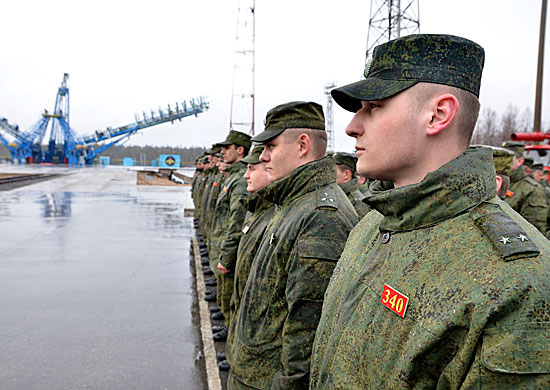
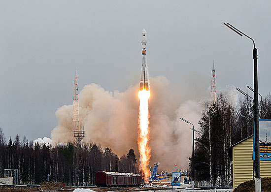
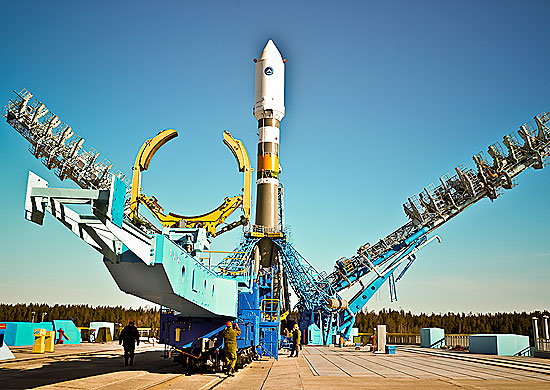
GLONASS-M satellite No. 47 was launched from the Plestesk Cosmodrome on April 26 at 05:23:41 UTC by a Soyuz 2-1b rocket.
“At 12.55 [08:55 UTC] the GLONASS-M spacecraft was taken under management by the Titov Main Test and Space Systems Control Centre. The spacecraft is installed [in orbit] and has maintained stable telemetry, and its onboard systems are operating normally,” said Colonel Alexei Zolotukhin of the Russian Aerospace Defence Forces.
The satellite, also known as Kosmos 2485 and GLONASS 747, was placed in orbital plane 1 and is drifting to its designated slot.
Initial two-line element set for the satellite:
1 39155U 13019A 13117.72709898 .00000014 00000-0 00000+0 0 85
2 39155 064.8833 235.0937 0113505 116.3660 245.7001 02.09126432 35
ISS Reshetnev, the manufacturer of the satellite, reported that the first communication session confirmed that the spacecraft is operating as designed, its mechanical systems deployed, and Sun and Earth acquisition was completed successfully.
According to the CEO – Chief Designer of ISS Reshetnev, Nicholas Testoedova, this GLONASS-M satellite will be a reserve. The following year, after the completion of the examinations and tests, it will replace one of the older exhausted units.
After reaching a designated orbit, likely slot 2 in orbital plane 1, the satellite will complete several weeks of commissioning and testing before entering regular service. There are currently 24 operational GLONASS satellites. The GLONASS-M satellite is the second generation GLONASS satellite.
Smartphone and tablet owners are spending less time using standalone consumer electronics (CE) devices according to new research study, “A Tale of Two Techs – Smartphone and Tablet Adoption and Usage,” released by the Consumer Electronics Association (CEA). The study shows consumers continue to use standalone electronic devices, such as digital cameras, but are reducing their usage time as a result of owning a smartphone or tablet.
According to the announcement, in households that own laptops, 43 percent of smartphone owners and 46 percent of tablet owners report spending less time with their laptops. However, very few users indicate they have stopped using their laptop computers altogether (one percent among smartphone owners, two percent tablet owners).
Compared to most standalone devices – with the exception of laptops – smartphones and tablets are being used more often and for more activities. Smartphones have become the primary device for taking pictures (78 percent), recording videos (74 percent), getting directions (69 percent), reading e-books (62 percent), listening to music (59 percent) and playing games (39 percent). Laptops and desktops remain the primary device smartphone and tablet owners use to browse the Internet, shop online, watch videos and view/edit documents.
The devices consumers indicate they are most likely to stop using altogether as a result of owning a smartphone and/or tablet are camcorders, portable audio/MP3 players, portable game devices, GPS or navigation devices and dedicated e-readers.
“Smartphones and tablets have enriched, diversified and transformed the ecosystem of consumer electronics,” said Rhonda Daniel, senior manager, market research, CEA. “As a result, mobile device owners are re-proportioning the time they spend using other standalone CE devices. While many single-function devices continue to play a distinct and relevant role in our digital lives, consumers are gravitating toward connected mobile devices able to perform multiple functions.”
An overwhelming majority of consumers are adopting smartphones and tablets in order to access the Internet. The study found that 85 percent of smartphone owners browse the Web and 89 percent check email on their devices. Among tablet owners, 92 percent browse the Web and 83 percent use their tablets to check email.
In addition, smartphones are frequently being used to take pictures (92 percent), make voice calls (91 percent) and navigate (76 percent). Conversely, tablets are used for more leisurely activities such as playing games (78 percent), watching videos (66 percent) and reading e-books (61 percent).
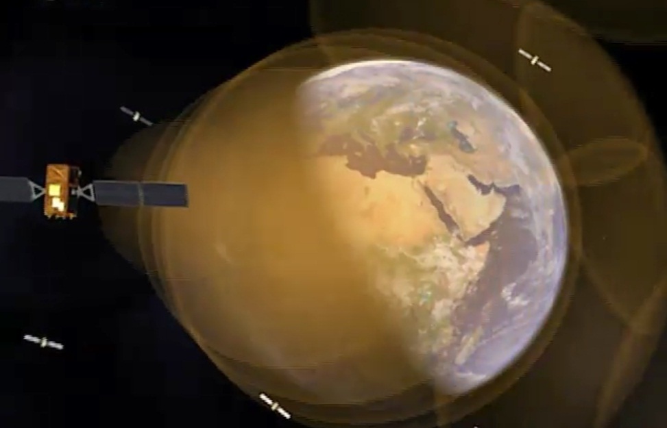
Europe’s four Galileo satellites are now working as clocks accurate to a few billionths of a second, disseminating the exact time through their signals expressed as the UTC Universal Coordinated Time global standard, reports the European Space Agency.
“A billionth of a second equals a nanosecond, a time interval far beyond our own human capacity of appreciation,” explains Marco Falcone, ESA’s Galileo System Manager.
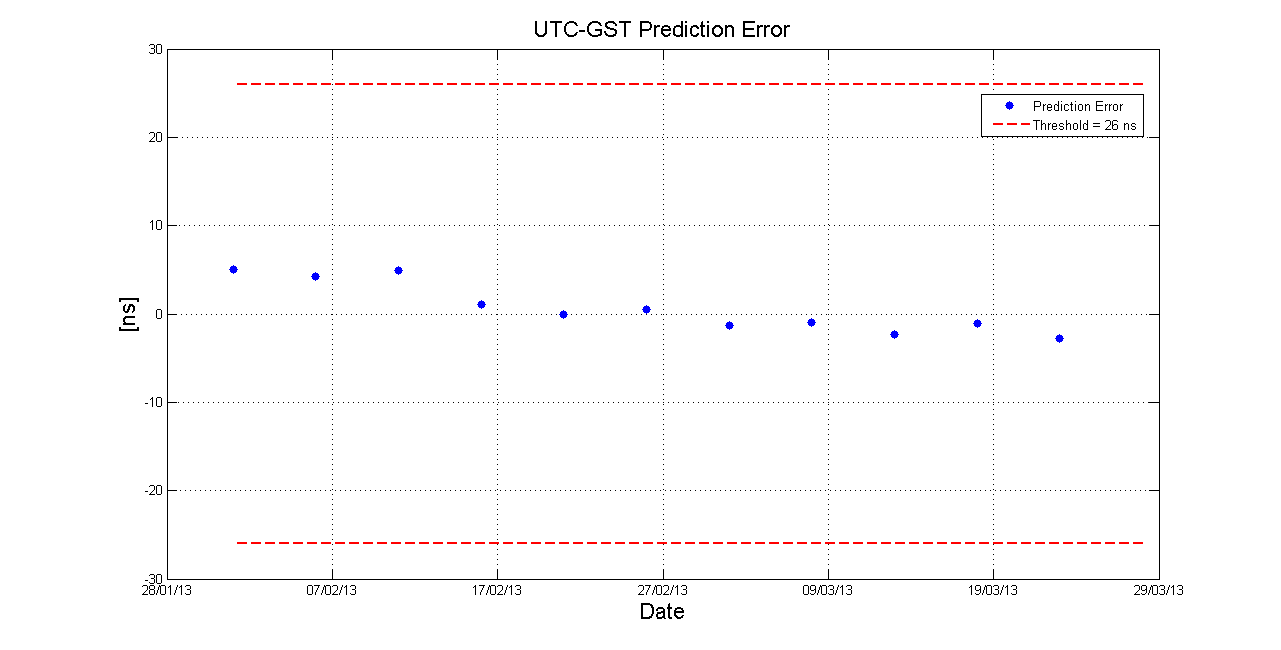
The prediction error for the offset between Galileo System Time and UTC, expressed in nanoseconds. The UTC value available to the user via Galileo is expected to be accurate within 26 nanoseconds, but in spring 2013 it has been even better, with a prediction error in the last two months of less than five nanoseconds.
“A single lightning flash across the sky during a thunderstorm lasts about ten milliseconds, which is already 10 000 000 nanoseconds. But for high-tech applications, as well as navigation services, nanosecond accuracy is essential.”
The replacement for Greenwich Mean Time, UTC is part of all our daily lives: it is the timing used for Internet, banking and aviation standards as well as precise scientific experiments, maintained by the Paris-based Bureau International de Poids et Mesures (BIPM).
The BIPM computes UTC based on inputs from collections of atomic clocks maintained by institutions around the world, including ESA’s ESTEC technical centre in Noordwijk, the Netherlands.
‘Galileo time’ is derived independently of UTC but is being kept close to it, with a precise ‘offset’ between the two values being calculated continuously and then disseminated through Galileo’s navigation message.
Galileo, like all other satellite navigation systems, is based on the highly precise measurement of time. A receiver on the ground pinpoints its position by calculating how long signals from satellites in orbit take to reach it.
Matching the receiver and satellite clocks then multiplying the time taken by the speed of light gives the range between user and satellite, allowing the receiver to fix its own location relative to four or more satellites.
“Each navigation system has its internal reference system time used to synchronise all system clocks and maintain overall coherence,” adds Marco.
Galileo’s navigation message embedded in its signals include precise timings based on Galileo System Time, kept close to global time standard UTC with a precise offset given, accurate to at least 26 nanoseconds.
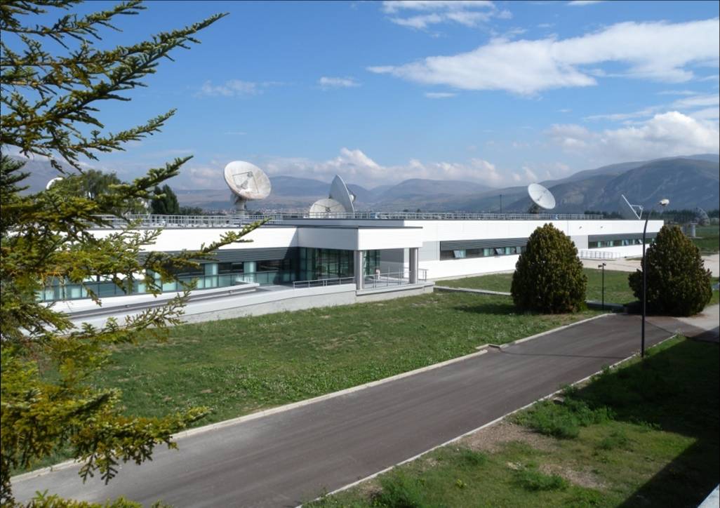
“Galileo runs on Galileo System Time, GST, which is fixed on the ground at the Galileo Control Centre in Fucino, Italy, by the Precise Timing Facility, based on the average of different atomic clocks.
“Strictly speaking, for navigation purposes alone this internal reference system time does not need to be in agreement with UTC at the highest level of accuracy but with this agreement being the case, it is therefore possible to immediately disseminate UTC to the users to the best accuracy and this is the aim of Galileo.”
The offset between GST and UTC is currently estimated in Turin, Italy, by the Istituto Nazionale di Ricerca Metrologica (INRIM), where time measurements are performed every day with the most precise techniques available to check GST status.
INRIM has been supporting ESA’s Galileo development since the early phases of the project. More recently INRIM has overseen the creation of a ‘Time Validation Facility’ for Galileo in collaboration with five other European time-measurement institutions: the Physikalisch Technische Bundesanstalt in Germany, the National Physics Laboratory in the UK, the Systeme de References Temps Espace/Observatoire de Paris in France, the Real Instituto y Observatorio de la Armada in Spain and Observatoire Royale de Belgique.
Galileo’s Ground Control Segment (GCS) in the Fucino Control Centre in Italy oversees Galileo navigation services and satellite payload operations.
Each day, the most precise European clocks and national time scales are compared to GST and the offset compared to UTC is estimated and provided to the Galileo Control Centre. This offset is then uploaded to the Galileo satellites for transmission in the navigation message available to users.
As explained by Patrizia Tavella from INRIM, “The UTC value available to the user via Galileo is expected to be accurate within 26 nanoseconds, but in the last two months it was even better, with a prediction error in the last two months of less than five nanoseconds.”