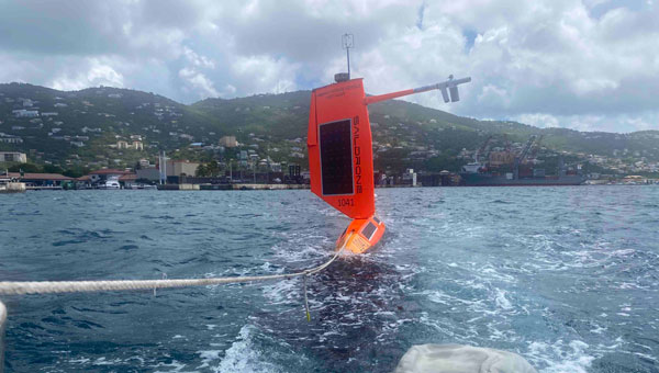
As Hurricane Beryl moved across the Caribbean, the National Oceanic and Atmospheric Administration (NOAA) has partnered with Saildrone to deploy seven hurricane-tracking saildrones in strategic locations.
These unmanned surface vessels (USVs) are equipped with a specialized “hurricane wing” to withstand extreme wind conditions. The USVs are gathering real-time data on key atmospheric and oceanic parameters such as wind speeds, wave heights, temperature, pressure and salinity.
Hurricane Beryl
Hurricane Beryl impacted Jamaica, the Cayman Islands and the Yucatan Peninsula. Residents were urged to complete preparations to protect life and property as the storm progressed.
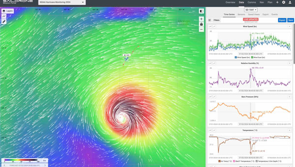
Two saildrones were deployed in the Gulf of Mexico, launched from St. Petersburg, Florida, and Port Aransas, Texas, and five more in the Atlantic Ocean and Caribbean Sea, launched from Jacksonville, Florida, and the U.S. Virgin Islands. These systems provide critical data to improve the understanding and prediction of tropical cyclone intensity changes, particularly rapid intensification — where hurricane wind speeds increase dramatically in a short period.
To enhance these efforts, Rutgers University deployed underwater gliders that work in tandem with saildrones. These gliders measure temperature and salinity at various depths, offering a detailed picture of the ocean’s conditions before, during and after a hurricane.
The collaboration aims to provide high-resolution, coordinated measurements from the ocean surface to the atmosphere, enhancing situational awareness for forecasters and improving the accuracy of hurricane intensity forecasts.
— NOAA Atlantic Oceanographic and Meteorological Lab (@NOAA_AOML) July 3, 2024
Advanced Technologies
Equipped with a “hurricane wing,” Saildrone’s USVs can collect continuous data in harsh storm conditions, providing real-time insights into the physical interactions between the ocean and atmosphere. Underwater gliders, deployed by Rutgers, aid in measuring subsurface ocean conditions, which are critical for understanding how variations in temperature and salinity affect hurricane strength.
The information gathered by these technologies is extremely valuable for enhancing predictive models, ultimately helping to improve disaster preparedness and response. The partnership between Saildrone, NOAA and Rutgers University represents a significant step forward in the use of uncrewed systems for environmental monitoring.
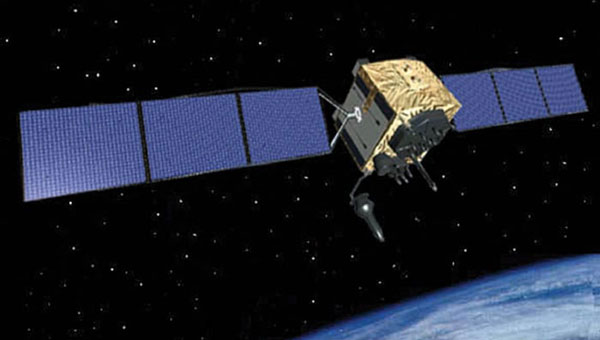
Researchers from the University of Texas at Austin have identified an Israeli air base as a large source of widespread GPS disruptions affecting civilian airline navigation in the Middle East, reported TheNew York Times.
The spoofing disruptions involve the transmission of manipulated GPS signals, which can cause airplane instruments to misread their location. Lead researchers Todd Humphreys and Zach Clements stated they are “highly confident” that Ein Shemer Airfield in northern Israel is the source of these attacks. The Israeli military declined TheNew York Times’request forcomment.
The research team utilized data emitted by the spoofer and picked up by satellites in low-Earth orbit (LEO) to determine its location. They then confirmed their calculations using ground data collected in Israel.
Spoofing, along with GPS jamming, has significantly increased over the past three years, especially near war zones such as Ukraine and Gaza. In these areas, militaries interfere with navigation signals to redirect aerial attacks.
The Middle East has emerged as a hotspot for GPS spoofing, with TheNew York Timesreporting that a separate analysis estimatesmore than50,000 flights have been affected in the region in 2024 alone. Researchers from SkAI Data Services and the Zurich University of Applied Sciences, analyzeding data from the OpenSky Network and, found that these attacks have led pilots to mistakenly believe they were above airports in Beirut or Cairo.
Swiss International Air Lines told TheNew York TimesNYTthat their flights are spoofed “almost every day over the Middle East.”
The issue extends beyond the region, with Estonia and other Baltic nations having blamed Russia for disrupting signals in their airspaces. Additionally, in April 2024, Finnair temporarily suspended flights to Tartu, Estonia, amid the rise of GPS jamming in the region affecting civilian air travel.
The attacks have not led to significant safety risks as pilots can use alternative navigation methods. However, they do raise concerns.
Jeremy Bennington, vice president of Spirent Communications, told TheNew York Times, “Losing GPS is not going to cause airplanes to fall out of the sky. But I also don’t want to deny the fact that we are removing layers of safety.”
The spoofing attacks may cause false alerts about planes being too close to the ground, leading to navigation confusion and possibly compromising flight safety.
As these disruptions continue to affect large areas far from active conflict zones, the aviation industry and international authorities are under increasing pressure to address this emerging threat to air travel security.
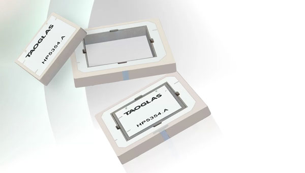
Taoglas has unveiled Inception, a new GNSS L1/L5 ultra-low-profile “patch-in-a-patch” antenna. The HP5354.A offers dual-band stacked patch performance in a single 35 x 35 x 4mm form factor. This design integrates the second antenna within the first, eliminating the need for stacking parts and reducing the antenna height by 50%.
The HP5354.A antenna features a passive, dual-feed surface mount design (SMD) designed to decrease weight and conserve horizontal space. This makes it suitable for GNSS applications requiring high precision and limited space. The antenna improves positioning accuracy from 3 m to 1.5 m while maintaining dual-band L1/L5 performance.
With a passive peak gain of 2.61 dBi, the HP5354.A can be used for GPS L1/L5, BeiDou B1, Galileo E1, and GLONASS G1 operations. Its dual-feed design maintains circular polarization gain even when the antenna is de-tuned or requires in-situ tuning.
It is ideal for applications such as asset tracking, smart agriculture, industrial tracking, commercial UAVs and autonomous vehicles. The HP5354.A uses Taoglas’ custom electro-ceramics formula, ensuring high-quality performance and seamless integration into devices requiring high-precision GNSS.
Emerging GNSS bands such as L2, L5, L6, and L-band offer pathways to cleaner signals, improved gain and centimeter-level accuracy. This trend is crucial for global GNSS technologies, including GPS, GLONASS, Galileo, BeiDou, QZSS, IRNSS, and SBAS.
With an ultra-low profile SMD, the antenna offers stack patch L1/L5 performance within a single-patch solution. It also maintains circular polarization gain with a dual-feed design.
The Taoglas HC125A hybrid coupler can combine the dual feeds for the L1 patch, offering high RHCP gain and optimal axial ratio for upper constellations including GPS L1, BeiDou B1, Galileo E1 and GLONASS G1. The Taoglas TFM.100B L1/L5 front-end module can be incorporated into the device PCB, aiming to save valuable real estate and up to two years of complex design work, according to the company.
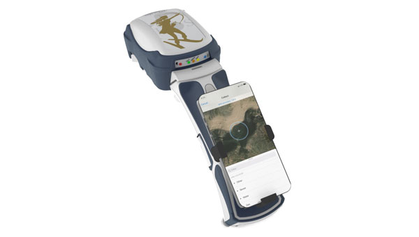
Eos Positioning Systems has released the Skadi Seriesproduct line. The Skadi Series consists of high-accuracy GNSS receivers designed to enhance field crews’ productivity, safety and flexibility.
Skadi Tilt Compensation allows users to capture data without needing to level their survey range pole. When activated on an RTK-enabled Skadi Series receiver, this feature allows users to rely on the receiver to correct errors caused by tilted range pole angles during data collection.
The Skadi Smart Handle introduces two additional features, powered by accurate lidar and MEMS sensor measurements. With the Skadi Smart Handle, users can activate an Invisible Range Pole to provide continuous elevation-to-the-ground measurements below the hand–held Skadi receiver.
The receiver computes accurate elevation to the ground, regardless of its attitude (angle toward the ground). The Invisible Range Pole eliminates the need to carry a physical range pole and the requirement to enter an antenna height in a field data collection app while performing RTK-level accurate fieldwork.
The Skadi Smart Handle also includes an Extensible Virtual Range Pole. This feature extends the reach of the user’s Invisible Range Pole beyond the position they physically occupy. The Extensible Virtual Range Pole allows users to measure the location of assets on the ground or in trenches up to 7m (23 ft) away while retaining high accuracy.
The series adds four new GNSS receivers with integrated antennas to the Eos offerings: the Skadi 100, Skadi 200, Skadi 300 and Skadi Gold with accuracies ranging from submeter to centimeter. The Skadi 200, Skadi 300 and the Skadi Gold are RTK enabled and are available for purchase with Skadi Tilt Compensation and the Skadi Smart Handle.
The European Union Aviation Safety Agency (EASA) has updated its Safety Information Bulletin (SIB) to address the growing number of GNSS outages and disruptions.
This updated advisory, SIB No. 2022-02R3, highlights the increasing sophistication and impact of GNSS jamming and spoofing, which have become significant concerns for aviation safety.
The bulletin is directed at competent authorities, Air Traffic Management/Air Navigation Services (ATM/ANS) providers, air operators, aircraft and equipment manufacturers and organizations involved in the design or production of ATM/ANS equipment. It aims to inform these stakeholders about the risks and necessary precautions related to GNSS interference.
Since February 2022, there has been a notable increase in GNSS jamming and spoofing, particularly in regions surrounding conflict zones and other sensitive areas such as the Mediterranean, Black Sea, Middle East, Baltic Sea and the Arctic, reports the EASA. These interferences can disrupt the accurate reception of GNSS signals, leading to various operational challenges for aircraft and ground systems.
Tackling jamming and spoofing
The bulletin addresses jamming and spoofing. Jamming involves intentional radio frequency interference that prevents GNSS receivers from receiving satellite signals, rendering the system ineffective or degraded, while spoofing involves broadcasting counterfeit satellite signals to deceive GNSS receivers, resulting in incorrect positioning, navigation and timing (PNT) data. Jamming typically results in immediate and noticeable effects, whereas spoofing is more difficult to detect and poses a higher safety risk.
Some symptoms of suspected GNSS spoofing include incoherence in navigation position, abnormal differences between ground speed and true airspeed, time and date shifts and spurious Terrain Awareness and Warning System (TAWS) alerts. These disruptions can lead to significant operational issues, such as re-routing or diversions, loss of Airborne Collision Avoidance System (ACAS) and misleading surveillance data.
EASA recommends several measures to reduce the risks associated with GNSS interference. These measures include establishing coordinated procedures between authorities, ATM/ANS providers and airspace users. The agency also suggests utilizing complementary PNT infrastructure and encourages users to implement a process to collect and report information on GNSS degradation.
Specific recommendations
For air operators:
Train flight crews to recognize and respond to GNSS interferences.
Promptly report any GNSS anomalies.
Assess operational risks and maintain alternative navigation procedures.
For ATM/ANS providers:
Establish monitoring and reporting processes for GNSS degradations.
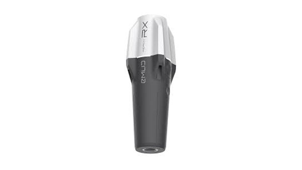
Emlid has released upgrades for its ultralight Reach RX Network real-time kinematics (RTK) rover. It features MFi (Made for iPhone/iPad) certification and is fully compatible with ArcGIS, QGIS and other GIS apps for both iOS and Android. Reach RX can be seamlessly integrated into GIS workflows to help industry professionals and teams collect accurate geodata at scale.
Reach RX offers precise positioning while receiving corrections through NTRIP. The device tracks GPS/QZSS, Galileo, GLONASS and BeiDou. It gets a fix in less than 5 seconds, delivering centimeter-level accuracy even in challenging conditions.
The rover does not require configuration or additional training— surveyors only need to add NTRIP credentials. With its intuitive and straightforward workflow, Reach RX allows users to achieve high precision for engineering, utility inspection, landscaping and other projects of any scale.
According to the company, the rover will soon be compatible with QField, Blue Marble’s Global Mapper, Mergin Maps, Avenza Maps and more.
The Reach RX rover weighs 250 grams. The battery provides 16 hours of operation on a single charge and can be recharged from a power bank. The receiver works in a variety of survival environments. The IP68-rated rover is waterproof, dustproof, and withstands temperatures from -20 to +65°C (-4 to 149°F).
3Dsurvey has launched 3Dsurvey 3.0, an all-in-one photogrammetric software solution.
3Dsurvey 3.0 is a hardware-agnostic solution designed to unify diverse data sources such as lidar sensors, cameras UAVs and various ground control points. The platform allows users to transition between orthophotos, point clouds and textured meshes, streamlining workflows without exporting files. This integration can benefit survey professionals, enhancing data accuracy and overall efficiency.
Version 3.0 features upgraded coordinate system functionalities to obtain georeferenced spatial data without the drawbacks of complex local transformations, which can reduce accuracy. These enhancements eliminate the need for third-party software.
3Dsurvey 3.0 has several features designed to improve geospatial data processing. Among the key updates is the improved coordinate system support, which handles transformations requiring special grid files. This upgrade ensures highly accurate GPS-to-local coordinate conversions. Additionally, the platform can automatically fetch missing geoid models, simplifying user workflow.
The revamped coordinate system selection process includes presets for users to find the correct system by simply entering their country name, with the appropriate settings applied automatically. It has PRJ file support to enhance compatibility with various GIS standards.
The new Clip function allows users to manage and share 3D models and orthophotos. By integrating CAD capabilities, users can import or create CAD lines within 3Dsurvey to define specific areas of interest, improving efficiency and data sharing.
In my last newsletter, I highlighted the release of a beta version of a new NOAA CORS Network (NCN) Station Web Page. As demonstrated in my newsletter, each CORS in the NCN has its own page with data, metadata, maps and photos for that station displayed in a modular layout so information is easily found all in one location. This past month, I had the privilege of participating in a meeting with representatives from the American Association for Geodetic Surveying (AAGS), the National Society of Professional Surveyors (NSPS) and the National Geodetic Survey (NGS). As a Past President of AAGS and the current Chair of the AAGS Membership Committee, I participate in these quarterly meetings.
AAGS aims to lead the community of geodetic, surveying, and land information data users through the 21st century. AAGS members develop new educational programs, including presentations, seminars, and workshops on topics related to geodetic surveying; and articles and papers that inform the membership of the latest scientific and technological developments and how to implement them in the most cost-effective and efficient manner.
In my previous newsletters, I have reminded everyone that time is running out to obtain a working knowledge of the new, modernized National Spatial Reference System (NSRS). The release of the new, modernized NSRS is only about a year away. As of July 2024, NGS plans to have a beta version of the new, modernized NSRS available around the summer of 2025 for users to test and evaluate new products and services. After enough testing has been performed, the new, modernized NSRS will be officially published – probably in early to mid-2026.
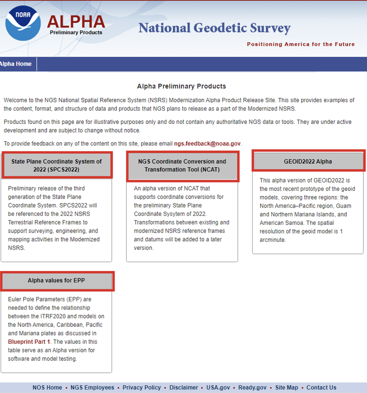
At the meeting, NGS highlighted some new products on its Alpha Preliminary Products site. The alpha site provides products that are useful for individuals who want to obtain a better understanding of the products that will be distributed as part of the new, modernized NSRS.
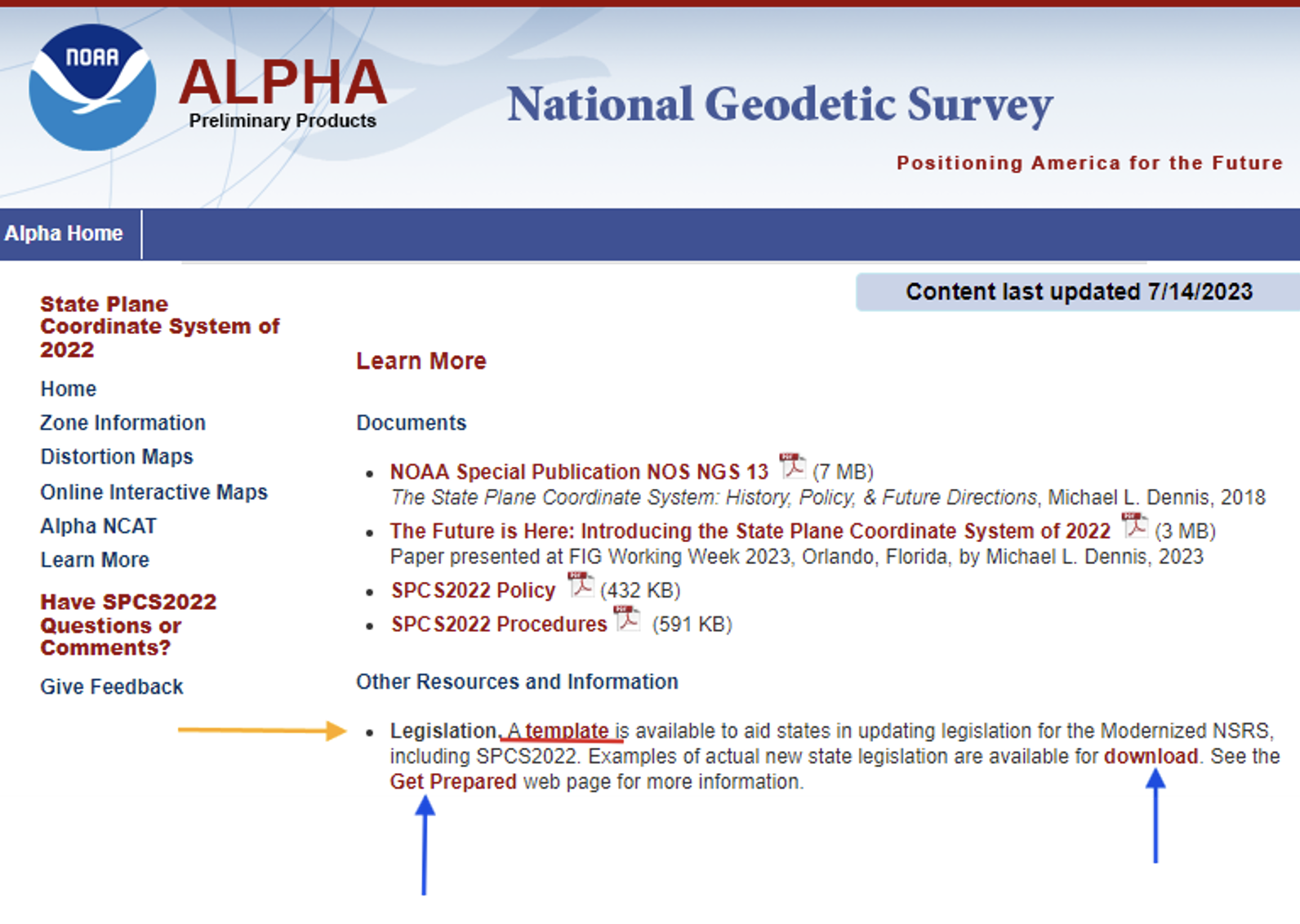
First, I want to bring attention to the importance of ensuring that the state’s legislation is modified or rewritten, if required, to include that the current horizontal and vertical datums are being replaced with the new, modernized NSRS. The “Learn More” button on the SPCS2022 Alpha site provides information about legislation.
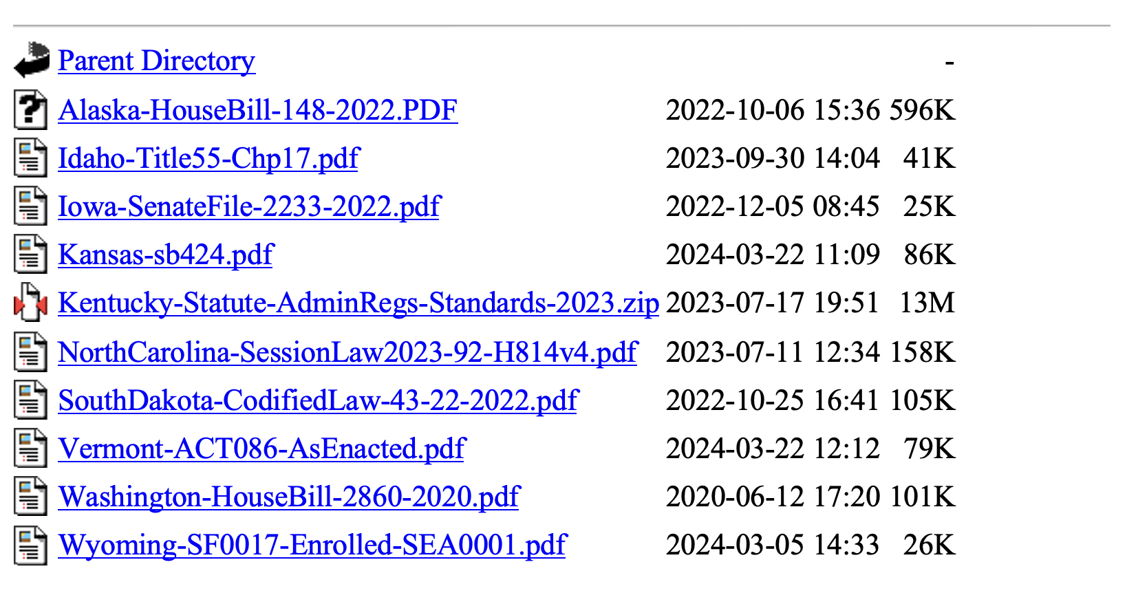
Per personal communication with Michael Dennis, Ph.D., NGS SPCS2022 Manager, as of June 26, 2024, the following 12 states have have enacted into law NSRS modernization: Alaska, Idaho, Iowa, Kansas, Kentucky, Louisiana, Nebraska, North Carolina, South Dakota, Vermont, Washington, and Wyoming.
Users can download examples of actual new state legislation here.
Examples of legislation.
During the joint AAGS/NSPS/NGS meeting, Tim Birch, the executive director of NSPS, said that anyone who has questions about updating legislation for the new, modernized NSRS, including SPCS2022, can contact him directly.NSPS has experience working with agencies and individuals to develop legislation as indicated in the following statement on the NSPS website.
“We are the voice of the professional surveying community in the US and its territories. Through its affiliation agreements with the respective state surveying societies, NSPS has a strong constituency base through which it communicates directly with lawmakers, agencies, & regulators at both the national and state level. NSPS monitors and comments on legislation, regulation, & policies that have potential impact on the activities of its members and their clients, and collaborates with a multitude of other organizations within the geospatial community on issues of mutual interest.”
As previously stated, the two latest alpha products are the “GEOID2022 Alpha” and “Alpha Values for EPP.” My December 2017 newsletter discussed GEOID 2022 and the North American-Pacific Geopotential Datum of 2022 (NAPGD2022), and my February 2022 newsletter discussed the Euler Pole Parameters process and use in the new, modernized NSRS.
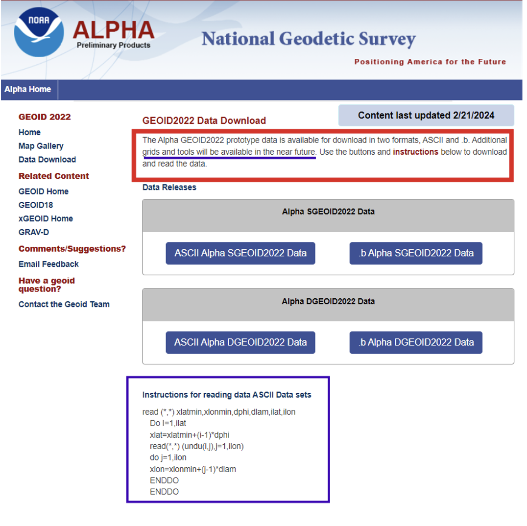
The GEOID2022 Alpha page provides a version of GEOID2022, which is the most recent prototype of the geoid models. The reference ellipsoid is Geodetic Reference System 1980 (GRS 80, but the geometric reference frame is ITRF2020). The Alpha GEOID2022 prototype data is available for download in two formats, “ASCII” and “.b.” There is a static component (SGEOID2022) and a dynamic component (DGEOID2022). These grids will be useful to programmers who want to develop and test their systems. Additional grids and tools will be available in the future.
Technical Details of the Alpha prototype of GEOID2022
GEOID2022 alpha is the last prototype of GEOID2022. It covers three regions: the North America–Pacific region, Guam and Northern Mariana Islands, and American Samoa. The spatial resolution of the geoid model is 1 arcminute. The geoid heights, which are in the tide-free system, are with respect to the reference ellipsoid of the Geodetic Reference System 1980 (GRS80) in the ITRF2020 geometric reference frame. GEOID2022 alpha includes static and dynamic components for the geoid heights. For detailed fundamental parameters of the geoid model, refer to NOAA Technical Report 78.
GEOID2022 Alpha
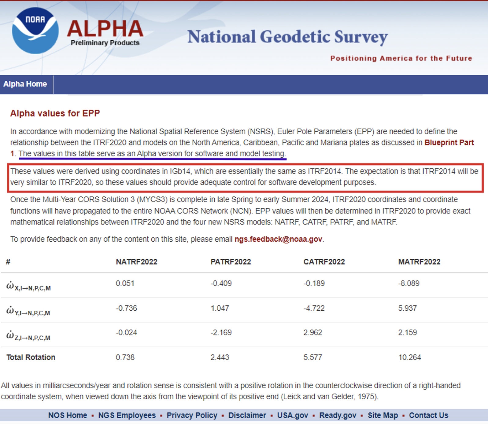
The Alpha EPP site provides the Euler Pole Parameters (EPP) that are needed to define the relationship between the ITRF2020 and models on the North America, Caribbean, Pacific and Mariana plates as discussed in NGS’s Blueprint Part 1 document.
Alpha Values for EPP
As stated in Blueprint Part 1, NGS will define the official relationship between ITRF2020 and the four NSRS TRFs through equation 59, using the rotation matrix in equation 58 resulting in equation 60.
I programmed this using a simple Excel spreadsheet to compute some of the potential changes between epochs for North Carolina. They were very similar to the ones that I depicted in my February 2022 newsletter that discussed the Euler Pole Parameters process and provided plots depicting the movement.
I would like to highlight the latest information available on the State Plane Coordinate System of 2022 alpha site. As previously stated, in about a year, the new, modernized NSRS will be available as a beta product. Users must get prepared by accessing NGS’s alpha products as well as taking the opportunity to provide feedback to NGS to improve their products and services. The Online Interactive Maps page provides information about the zones for every U.S. state and territory.
Clicking on the Online Interactive Maps link opens a NOAA ArcGIS online website that provides information about the Alpha State Plane Coordinate System 2022 preliminary zone designs. I have highlighted a few items that may be of interest to users.
The site provides a description of the site, links to various types of zones, links to data sources and information about distortion.
SPCS2022 online interactive maps.
Clicking on the link for zone definitions provides a list of zones and their parameters. This same information is also provided when users click on a zone on the map. I will demonstrate this later in this newsletter.
Per personal communication with Dennis, as of June 26, 2024, seven states have some or all their SPCS2022 zone definitions formally finalized, consisting of 205 out of the 965 zones (the total number of zones is still preliminary):
Alaska (partial coverage multizone layer)
Arizona (both multizone layers)
Idaho (both multizone and statewide)
Kentucky (both multizone and statewide)
North Carolina (statewide zone; it has no other zones)
South Dakota (both multizone and statewide)
Wisconsin (multizone)
Dennis informed me that the information on the alpha SPCS2022 Experience has been updated. He told me that the total number of zones decreased from 967 to 965, but based on coordination with the International Association of Oil & Gas Producers (IOGP) Geodesy Subcommittee the number may eventually increase to 972 (more about that in a future newsletter).
He stated that his goal is to finalize the zone definitions by the end of this calendar year or early 2025. Users should keep checking the alpha site.
Dennis mentioned that the website now offers a new feature that provides the distortion value when users click on the map. A nice thing about that is the site can be used on a smartphone, allowing users to obtain real-time distortion information from their location.
Clicking on the link titled “View” in the upper right corner of the box brings up a map that depicts the SPCS2022 zones.
View of ALPHA (preliminary) SPCS2022 zone designs.
When you click on the note about the ALPHA being preliminary, the map underneath appears where the user can select the type of maps they wish to review.
The following options are available: All Zone Layers, Statewide Zone Layers, Multizone Complete Layers, Multizone Partial Layers, and Special Use Zone Layers.
Users can use their mouses or the “+” button on the left-hand side” to zoom to a particular region, or use the search button on the right-hand side to select a State or zone.
Using the search box.
Information about a particular zone pops up by clicking on a point on the map.
Detailed information provided for a zone.
Each zone provides links to other features based on the location of the point selected on the map.
The image below provides the distortion in ppm for the point selected on the map.
The Alpha NCAT site can be used to obtain an estimate of the changes between SPCS83 and SPCS2022. It should be noted that all values will be in meters (m) and international feet (ft).
International feet may be new to some surveyors who were previously using the U.S. survey feet in SPCS83. The U.S. survey foot will not be used with the NSRS, including SPCS2022 coordinates. NGS and the National Institute of Standards and Technology (NIST) have taken action to deprecate the U.S. survey foot. What does that mean?. NIST has the following statement on its website: “Beginning on January 1, 2023, the U.S. survey foot should be avoided, except for historic and legacy applications, and has been superseded by the international foot.” This means that NGS will not be publishing SPCS2022 in U.S. survey feet but all historic products and services such as SPCS83 will still be provided in U.S. survey feet (sft) and international feet (ift).
More information and resources about the deprecation of the sft are listed below (personal communication from Dennis):
The official announcement is the final determinationFederal Register Notice (FRN) on deprecation of the sft issued on 10/5/2020. It was jointly issued by the National Institute of Standards and Technology (NIST) and NGS. I encourage everyone concerned about this topic to read it closely and in its entirety; it can likely answer most questions. The FRN includes information on the continued use of sft for legacy applications (such as SPCS 83). That is stated in the last paragraph of the “Notice of Final Determination” section; in items #1 and #2 in the “Counterpoints to Feedback Expressing Opposition”section; and in the second paragraph of the “Implementation Summary and Actions” section.
The legacy issue is also addressed in the 10th FAQon the NIST website and in the 11th FAQon our “new datums” FAQs web page.
The 40 states that officially adopted the sft for SPCS 83 are listed in Table C.1 of Appendix C of NOAA Special Publication NOS NGS 13, “The State Plane Coordinate System History, Policy, and Future Directions.”
Although the final determination FRN is itself not a law, Congress has passed several laws giving NIST the authority to maintain national standards of measurement. These and other related federal laws are given in the initial sft FRNissued on 10/17/2019.
An NGS webinar given on 11/10/2022 addresses the deprecation of the sft in the context of state plane. Two previous NGS webinars also provide additional background and historical information on the sft, one given on 4/25/2019 and the other on 12/12/2019.
Input to Alpha NCAT.Photo:Output from Alpha NCAT.
This newsletter highlighted the products on NGS’s Alpha Preliminary Products site. The alpha site provides products that can be useful for individuals to obtain a better understanding of the products that will be distributed as part of the new, modernized National Spatial Reference System (NSRS). NGS is providing these products on an alpha site so that they can get feedback from users. I would encourage all users to access the alpha sites and provide comments to NGS so that their products and services better meet the needs of the surveying and mapping community.
Welcome to the NGS National Spatial Reference System (NSRS) Modernization Alpha Product Release Site. This site provides examples of the content, format, and structure of data and products that NGS plans to release as a part of the Modernized NSRS.
Products found on this page are for illustrative purposes only and do not contain any authoritative NGS data or tools. They are under active development and are subject to change without notice.
To provide feedback on any of the content on this site, please email [email protected].
Swift Navigation and Calian, formerly Tallysman, have partnered to integrate precise positioning into location-based products across a variety of industries.
Autonomous vehicles and robots are complex and costly to build. Developers must integrate advanced hardware and software, do extensive testing and validation, maintain complex infrastructure, and calibrate diverse components and systems to ensure seamless compatibility. To address these challenges, Calian’s fully integrated GNSS hardware is now compatible with Swift’s Skylark Precise Positioning Service.
Calian’s smart antennas are available in a ceramic patch design, based on its Tallysman Accutenna technology, ideal for stationary or vehicle-mounted applications, such as precise navigation, enhanced driver safety and robotics. It is also offered in a helical form factor, designed for portable and lightweight devices where size, weight and durability are critical, such as UAVs and wearables.
When paired with Skylark’s GNSS corrections, the antennas offer centimeter-level accuracy, uniform performance and fast convergence. Skylark’s subscription model removes the need to maintain ground reference stations or the risk of relying on unreliable public ones. It leverages observations from its extensive network to model corrections for entire countries, which are then delivered directly to receivers via the internet.
Calian offers development kits that include the smart antenna, an RS-232, RS-422 or USB digital interface and the TruPrecision evaluation software, allowing developers to quickly evaluate Skylark with the many compatible Calian antennas.
Landscape of Badwater Basin salt flats, with halite textures under a vibrant pink sky during sunset or sunrise at Death Valley National Park. (Photo: StephenBridger / iStock / Getty Images Plus / Getty Images)
The U.S. Geological Survey (USGS) has commissioned Woolpert to collect Quality Level 1 lidar data and conduct ground control surveys throughout Southern California in support of the 3D Elevation Program (3DEP) and The National Map.
Overseen by the USGS National Geospatial Program, 3DEP provides the nation’s first comprehensive, high-resolution topographic elevation data integrated into The National Map. The data will be accessible to local, state and national agencies to consider when making decisions that affect the immediate safety of life, property and the environment, as well as for long-term infrastructure planning.
Woolpert will collect roughly 60,000 km2 of aerial lidar data throughout Inyo County, California, including parts of the Mojave Desert and Death Valley National Park, using a Leica TerrainMapper. QL1 data are collected at eight points per square meter.
“Woolpert has had the honor of supporting USGS’ 3D Elevation Program since its launch nearly a decade ago,” said John Gerhard, Woolpert vice president and program director. “Critical decisions that depend on accurate and available elevation data are being made every day, and we are incredibly proud to continue our support for the U.S. Geological Survey and its commitment to completing the nation’s first-ever baseline of consistent high-resolution elevation data.”
Gerhard added that the data acquired for this project will also support the USGS 3D Hydrography Program (3DHP). The project is underway, and data is expected to be acquired by fall 2024.
[SPONSORED CONTENT] LabSat has announced the launch of the LabSat 4 GNSS Simulator, a cutting-edge solution for modern GNSS signal testing. With three configurable RF channels, up to 12-bit I&Q quantization, and variable 10-60 MHz bandwidth, it offers exceptional customization and precision. Synchronized record and replay of external data sources such as CAN FD and RS232 further enhance complex test scenarios.
LabSat 4 has been engineered to deliver ease of use, with saveable custom record settings and a web-based interface for effortless configuration. Its impressive file management capabilities, featuring 7.6TB internal storage and fast data transfer via Gigabit Ethernet and USB 3.0, meet high-volume data demands efficiently. Maintaining the compact size, portability, and cost efficiency of its predecessors, LabSat 4 is ideal for use both in the field and laboratory. Additionally, it integrates seamlessly with SatGen Simulation Software, enabling the creation of detailed GNSS RF I&Q scenario files based on custom trajectories, enhancing its utility for sophisticated GNSS signal testing.
uAvionix has successfully installed and approved its surface situational awareness systems at two major U.S. airports: Indianapolis International Airport (IND) and Austin-Bergstrom International Airport (AUS). Developed in collaboration with Capital Sciences, the systems have passed the Service Acceptance Test (SAT) and will be operational for Air Traffic Control (ATC) starting June 30, 2024.
“This milestone marks the first approvals under the Federal Aviation Administration (FAA) Surface Awareness Initiative (SAI), part of a broader effort to enhance runway safety across the nation,” said Christian Ramsey, chief commercial officer for uAvionix.
The uAvionix systems use the Automatic Dependent Surveillance-Broadcast (ADS-B) service called FlightLine, which offers controllers real-time, precise depictions of aircraft and vehicles on the airport surface. This technology seeks to improve situational awareness and reduce the risk of runway incursions.
The delivery of the FlightLine systems to IND and AUS was completed and accepted within a 90-day timeframe, thanks to close collaboration with the FAA, National Air Traffic Control Association (NATCA), Indianapolis Airport Authority and AUS.
Each airport also installed several of uAvionix’s VTU-20 ADS-B Vehicle Movement Area Transmitters (VMATs) on airport vehicles. The VTU-20 is an FAA-approved system that allows vehicles operating on runways and taxiways to be electronically seen by the tower and aircraft equipped with ADS-B In technologies, further reducing the risk of runway incursions.
Following the success of these implementations, uAvionix will continue working with the FAA to expand the capability to other airports nationwide.
Key benefits of the enhanced system include:
Improved real-time tracking of aircraft and vehicles on the airfield.
Increased safety and efficiency in all weather conditions.
Decreased risk of runway incursions due to timely and accurate data.